WO2019021391A1 - Climatiseur - Google Patents
Climatiseur Download PDFInfo
- Publication number
- WO2019021391A1 WO2019021391A1 PCT/JP2017/027052 JP2017027052W WO2019021391A1 WO 2019021391 A1 WO2019021391 A1 WO 2019021391A1 JP 2017027052 W JP2017027052 W JP 2017027052W WO 2019021391 A1 WO2019021391 A1 WO 2019021391A1
- Authority
- WO
- WIPO (PCT)
- Prior art keywords
- notch
- plane
- main plate
- axial direction
- air conditioner
- Prior art date
- Legal status (The legal status is an assumption and is not a legal conclusion. Google has not performed a legal analysis and makes no representation as to the accuracy of the status listed.)
- Ceased
Links
Images




Classifications
-
- F—MECHANICAL ENGINEERING; LIGHTING; HEATING; WEAPONS; BLASTING
- F24—HEATING; RANGES; VENTILATING
- F24F—AIR-CONDITIONING; AIR-HUMIDIFICATION; VENTILATION; USE OF AIR CURRENTS FOR SCREENING
- F24F1/00—Room units for air-conditioning, e.g. separate or self-contained units or units receiving primary air from a central station
- F24F1/0007—Indoor units, e.g. fan coil units
- F24F1/0018—Indoor units, e.g. fan coil units characterised by fans
- F24F1/0022—Centrifugal or radial fans
-
- F—MECHANICAL ENGINEERING; LIGHTING; HEATING; WEAPONS; BLASTING
- F04—POSITIVE - DISPLACEMENT MACHINES FOR LIQUIDS; PUMPS FOR LIQUIDS OR ELASTIC FLUIDS
- F04D—NON-POSITIVE-DISPLACEMENT PUMPS
- F04D29/00—Details, component parts, or accessories
- F04D29/26—Rotors specially for elastic fluids
- F04D29/28—Rotors specially for elastic fluids for centrifugal or helico-centrifugal pumps for radial-flow or helico-centrifugal pumps
- F04D29/281—Rotors specially for elastic fluids for centrifugal or helico-centrifugal pumps for radial-flow or helico-centrifugal pumps for fans or blowers
-
- F—MECHANICAL ENGINEERING; LIGHTING; HEATING; WEAPONS; BLASTING
- F04—POSITIVE - DISPLACEMENT MACHINES FOR LIQUIDS; PUMPS FOR LIQUIDS OR ELASTIC FLUIDS
- F04D—NON-POSITIVE-DISPLACEMENT PUMPS
- F04D29/00—Details, component parts, or accessories
- F04D29/26—Rotors specially for elastic fluids
- F04D29/28—Rotors specially for elastic fluids for centrifugal or helico-centrifugal pumps for radial-flow or helico-centrifugal pumps
- F04D29/30—Vanes
-
- F—MECHANICAL ENGINEERING; LIGHTING; HEATING; WEAPONS; BLASTING
- F05—INDEXING SCHEMES RELATING TO ENGINES OR PUMPS IN VARIOUS SUBCLASSES OF CLASSES F01-F04
- F05D—INDEXING SCHEME FOR ASPECTS RELATING TO NON-POSITIVE-DISPLACEMENT MACHINES OR ENGINES, GAS-TURBINES OR JET-PROPULSION PLANTS
- F05D2240/00—Components
- F05D2240/20—Rotors
- F05D2240/30—Characteristics of rotor blades, i.e. of any element transforming dynamic fluid energy to or from rotational energy and being attached to a rotor
- F05D2240/304—Characteristics of rotor blades, i.e. of any element transforming dynamic fluid energy to or from rotational energy and being attached to a rotor related to the trailing edge of a rotor blade
Definitions
- the present invention relates to an air conditioner provided with a turbofan.
- Patent Document 1 describes an air conditioner.
- the air conditioner has a centrifugal fan and a heat exchanger disposed around the centrifugal fan.
- the impeller of the centrifugal fan includes a hub attached to the motor shaft, a shroud disposed opposite to the hub, and a plurality of vanes disposed between the outer periphery of the hub and the outer periphery of the shroud. There is.
- the suction port of the centrifugal fan is formed at the central portion of the shroud, and the outlet of the centrifugal fan is formed at the outer peripheral portion of the impeller.
- the centrifugal fan In the centrifugal fan, air is drawn into the impeller along the axial direction from the suction port. For this reason, the air drawn into the interior of the impeller has an axial momentum moving from the shroud to the hub. Moreover, in the case of a low pressure centrifugal fan mounted on an air conditioner, the radial length of the blade is relatively short. Therefore, the air blown out from the outlet of the centrifugal blower has an air volume distribution biased toward the hub side in the axial direction.
- the air blown out from the outlet of the centrifugal blower flows into a heat exchanger disposed around the centrifugal blower.
- the heat exchangers are disposed in the axial direction so as to be biased toward the shroud side rather than the hub side with respect to the blower outlet of the centrifugal fan. For this reason, the deviation of the air volume distribution of the air flowing into the heat exchanger is larger than the deviation of the air volume distribution of the blown air at the outlet of the centrifugal fan.
- the heat exchanger is a resistor to the flow of air. For this reason, when the air with uneven air volume distribution flows into the heat exchanger, the imbalance of the air volume distribution is alleviated with the loss of dynamic pressure. Therefore, in the air conditioner of patent document 1, since the loss of energy becomes large, the subject that the required motive power will become large occurred.
- the present invention has been made to solve the problems as described above, and it is an object of the present invention to provide an air conditioner having a small required power and excellent energy saving performance.
- An air conditioner comprises a turbofan having an impeller and a fan motor for driving the impeller, and a heat exchanger disposed on the leeward side of the impeller, wherein the impeller is A main plate connected to a drive shaft of the fan motor, a side plate disposed opposite to the main plate and having a suction port formed at its central portion, and a plurality of wings provided between the main plate and the side plate , And each of the plurality of wings has a leading edge and a trailing edge disposed radially outward of the leading edge with respect to the turbofan, and the trailing edge is provided on the trailing edge.
- each of the plurality of wings is a pair of sides facing each other across the notch, a first side located on the main plate side of the notch, and the notch And a second side located on the side plate side of the It is what is formed so as to project on the plate side.
- the flow direction of air along the second side can be bent to the side plate side, it is possible to alleviate the deviation of the air volume distribution of the air flowing into the heat exchanger. Therefore, it is possible to reduce the loss of dynamic pressure that occurs in the air from the impeller to the heat exchanger before it is blown out, so it is possible to obtain an air conditioner with a small required power and excellent energy saving performance.
- FIG. 1 It is a schematic diagram which shows the cross-sectional structure of the air conditioner concerning Embodiment 1 of this invention. It is a figure which expands and shows the structure of the wing
- FIG. 1 is a schematic view showing a cross-sectional configuration of the air conditioner according to the present embodiment.
- disconnected the air conditioner in the meridional plane of the turbo fan 10 is shown.
- the meridional plane is a plane including the axial center O of the turbo fan 10.
- the shapes of the wings 15 shown in FIG. 1 and FIGS. 2 to 8 described later are rotational projections of one of the plurality of wings 15 on the meridional plane of the turbofan 10.
- the air conditioner includes a turbofan 10 having an impeller 11 and a fan motor 12 for driving the impeller 11, a heat exchanger 20 disposed on the leeward side of the impeller 11, and a turbofan. And a case 21 for housing the heat exchanger 20.
- the fan motor 12 of the turbo fan 10 is fixed to the central portion of the top surface of the housing 21.
- the axial center O of the turbo fan 10 extends in the vertical direction.
- the heat exchanger 20 is disposed so as to surround the outer periphery of the impeller 11, and has a frame shape that is substantially square when viewed in the direction along the axis O.
- the heat exchanger 20 together with a compressor, an outdoor heat exchanger, and an expansion valve (not shown), constitutes a refrigeration cycle for circulating a refrigerant.
- the heat exchanger 20 functions as an evaporator during the cooling operation, and functions as a condenser during the heating operation.
- an air inlet 22 of an air conditioner for sucking room air into the housing 21 is formed.
- An air conditioner outlet 23 for blowing out the conditioned air having passed through the heat exchanger 20 from the inside of the housing 21 to the room is formed around the suction port 22 in the lower surface of the housing 21.
- four outlets 23 for blowing the conditioned air in four different directions are provided.
- the impeller 11 includes a main plate 13 connected to the drive shaft 12 a of the fan motor 12, a ring-shaped side plate 14 disposed facing the main plate 13, and a plurality of the plates provided between the main plate 13 and the side plate 14. And a wing 15.
- a suction port 16 of the impeller 11 is formed in a circular shape about the axis O.
- the suction port 16 of the impeller 11 is disposed to face the suction port 22 of the air conditioner.
- a bell mouth 18 for guiding room air sucked from the suction port 22 to the suction port 16 is provided.
- the blower outlet 17 of the impeller 11 is formed in the outer peripheral part of the impeller 11.
- the plurality of wings 15 are arranged at equal intervals or unequal intervals in the circumferential direction centering on the axial center O.
- Each of the plurality of wings 15 has the same shape. Details of the shape of the wing 15 will be described later.
- the impeller 11 When the impeller 11 is rotated about the axial center O by the driving force of the fan motor 12, the room air sucked into the housing 21 through the suction port 22 of the air conditioner is guided by the bell mouth 18, and the blades It is sucked into the impeller 11 from the suction port 16 of the car 11.
- the indoor air sucked into the impeller 11 passes between the vanes of the two wings 15 adjacent in the circumferential direction, and is blown out from the outlet 17 of the impeller 11 to the outer circumferential side.
- the indoor air blown out to the outer peripheral side of the impeller 11 passes through the heat exchanger 20, is cooled or heated by heat exchange with the refrigerant, and becomes conditioned air.
- the conditioned air is blown out into the room from the air outlet 23 of the air conditioner.
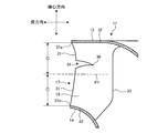
- FIG. 2 is an enlarged view of the configuration of the wing 15 in the air conditioner according to the present embodiment.
- the vertical direction in FIG. 2 represents the axial direction along the axial center O of the turbo fan 10 and the impeller 11.
- the left and right direction in FIG. 2 represents the radial direction of the turbo fan 10 and the impeller 11. In the range shown in FIG. 2, the left direction represents the radially outer side, and the right direction represents the radially inner side.
- the wing 15 has an upper end 32 joined to the lower surface of the main plate 13 and a lower end 33 joined to the upper surface of the side plate 14.
- the wing 15 also has a leading edge 30 and a trailing edge 31 disposed rearward of the leading edge 30 in the rotational direction of the impeller 11.
- the trailing edge 31 is disposed outside the leading edge 30 in the radial direction.
- Both the front edge 30 and the rear edge 31 extend from the upper end 32 to the lower end 33.
- the end on the upper end 32 side of the rear edge 31 and the end on the lower end 33 side may be referred to as a main plate side end 31a and a side plate side end 31b, respectively.
- a part of the trailing edge 31 is formed with a substantially triangular notch 34. That is, the notch 34 has a shape which is cut out in a substantially triangular shape from the rear edge 31 to the front edge 30.
- the wing 15 has a first side 35 a located closer to the main plate 13 than the notch 34 in the axial direction as a pair of sides facing each other across the notch 34, and the side plate 14 than the notch 34 in the axial direction. And a second side 35b located on the side.
- the range of the notch 34 is from the first connection point 37 where the first side 35 a and the rear edge 31 are connected to the second connection point 38 where the second side 35 b and the rear edge 31 are connected.
- the radially innermost portion of the notch 34 is the bottom 36 of the notch 34.
- the bottom 36 is located between the first connection point 37 and the second connection point 38. That is, the bottom portion 36 is located between a plane perpendicular to the axial direction and including the first connection point 37 and a plane perpendicular to the axial direction and including the second connection point 38.
- the first side 35 a connects between the first connection point 37 and the bottom portion 36.
- the second side 35 b connects between the second connection point 38 and the bottom 36. Since the notch 34 of the present embodiment is generally triangular, the bottom 36 has a point shape.
- the depth dimension D1 of the notch 34 in the radial direction is defined as the distance between the second connection point 38 and the bottom 36 in the radial direction. That is, the depth dimension D1 is equal to a value obtained by subtracting the distance between the bottom portion 36 and the axial center O from the distance between the second connection point 38 and the axial center O. Further, the width dimension W1 of the notch 34 in the axial direction is defined as the distance between the first connection point 37 and the second connection point 38 in the axial direction. The depth dimension D1 is larger than the width dimension W1 (D1> W1). Further, the depth dimension D1 is equal to or greater than 1/4 of the distance between the leading edge 30 and the trailing edge 31 in the radial direction.
- the second side 35 b is formed in a smooth curve that is convex toward the main plate 13 over the whole. That is, the second side 35 b is formed to be convex with respect to the notch 34.
- the second side 35 b has, for example, an arc shape.
- the first side 35 a is formed in a smooth curve shape that is convex toward the main plate 13 side over the whole. That is, the first side 35 a is formed to be concave with respect to the notch 34.
- the first side 35 a has, for example, an arc shape.
- FIG. 3 is an enlarged view of the configuration of the wing 15 in the air conditioner according to the present embodiment.
- the notch 34 is formed closer to the main plate 13 in the rear edge 31.
- an imaginary plane located in the middle of the main plate side end 31a of the rear edge 31 and the side plate side end 31b in the axial direction is a first plane P1
- the bottom 36 of the notch 34 is It is located closer to the main plate 13 than the first plane P1.
- the first plane P1 is a plane perpendicular to the axial direction, and is a plane in which the distance from the main plate side end 31a and the distance from the side plate side end 31b are equal.
- FIG. 4 is a view showing the positional relationship between the wing 15 and the heat exchanger 20 in the air conditioner according to the present embodiment.
- the heat exchanger 20 is disposed so as to be biased to the side plate 14 side rather than the main plate 13 side with respect to the air outlet 17 of the turbo fan 10.
- the second plane P2 is a first plane, assuming that an imaginary plane located midway between the upper end 20a and the lower end 20b of the heat exchanger 20 in the axial direction is the second plane P2. It is located closer to the side plate 14 than P1.
- the second plane P2 is a plane perpendicular to the axial direction, and is a plane in which the distance from the upper end 20a and the distance from the lower end 20b are equal.
- the bottom portion 36 of the notch 34 is located closer to the main plate 13 than the first plane P1, and naturally is located closer to the main plate 13 than the second plane P2.
- the wings 15 push air on the pressure side and act to draw air on the suction side. This action is the same around the notch 34.
- the air reaching the bottom portion 36 of the notch 34 from the leading edge 30 along the wing surface on the pressure side or suction side of the wing 15 is the trailing edge from the bottom portion 36 along the first side 35 a or the second side 35 b It flows to the 31 side.
- the air flow direction from the bottom 36 to the rear edge 31 along the first side 35 a also gradually approaches the rear edge 31. To the side plate 14 side.
- the notch 34 is formed at the trailing edge 31 of the wing 15 to make the air volume distribution of the air blown out from the outlet 17 of the impeller 11 more uniform, and the main plate 13 side of the air volume distribution in the axial direction Bias is mitigated.
- the bias of the air volume distribution of the air flowing into the heat exchanger 20 is also alleviated. Therefore, according to the present embodiment, it is possible to reduce the loss of dynamic pressure generated in the air from the blowout port 17 of the impeller 11 to the flow into the heat exchanger 20. For this reason, it is possible to obtain an air conditioner having a small required power and excellent energy saving performance.
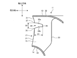
- FIG. 5 is a figure which shows the 1st modification of a structure of the wing
- a substantially trapezoidal notch 34 is formed at the trailing edge 31 of the wing 15 of the present modification.
- the bottom portion 36 is formed in a straight line along the axial direction.
- the other configuration is the same as the configuration shown in FIGS. Even with the configuration of this modification, the air that has reached the bottom 36 of the notch 34 from the leading edge 30 along the wing surface of the wing 15 is along the first side 35 a or the second side 35 b from the bottom 36 It flows to the trailing edge 31 side. Therefore, the same effect as the configuration shown in FIGS. 1 to 4 can be obtained by this modification as well.
- FIG. 6 is a view showing a second modified example of the configuration of the wing 15 in the air conditioner according to the present embodiment.
- an R portion 35 a 1 is formed in a portion of the first side 35 a adjacent to the first connection point 37.
- An R portion 35b1 is formed in a portion adjacent to the second connection point 38 in the second side 35b.
- the range of the notch 34 is from the first connection point 37 to the second connection point 38.
- the first side 35 a is formed in a smooth curved shape which is convex toward the main plate 13 side substantially over the entire area except for the R portion 35 a 1.
- the second side 35 b is formed in a smooth curved shape that is convex toward the main plate 13 side over the entire area including the R portion 35 b 1.
- the same effect as the configuration shown in FIGS. 1 to 4 can be obtained by this modification as well.
- the air conditioner according to the present embodiment includes the turbofan 10 having the impeller 11 and the fan motor 12 for driving the impeller 11, and the heat exchange disposed on the leeward side of the impeller 11 And a vessel 20.
- the impeller 11 has a main plate 13 connected to the drive shaft 12 a of the fan motor 12, a side plate 14 disposed opposite to the main plate 13 and having a suction port 16 formed at its center, the main plate 13 and the side plate 14 And a plurality of wings 15 provided therebetween.
- Each of the plurality of wings 15 has a leading edge 30 and a trailing edge 31 disposed radially outside the leading edge 30 in the turbo fan 10.
- a notch 34 is formed in the rear edge 31.
- Each of the plurality of wings 15 is a first side 35 a located on the main plate 13 side of the notch 34 and a second side located on the side plate 14 side of the notch 34 as a pair of sides facing each other across the notch 34. And a side 35b.
- the second side 35 b is formed to be convex toward the main plate 13 side.
- the end positioned on the main plate 13 side is the main plate side end 31a, and the end positioned on the side plate 14 of the both ends of the rear edge 31.
- the plane from which the distance from the main plate side end 31a is equal to the distance from the side plate side end 31b is a first plane.
- a portion P1 of the notch 34 located radially inward in the radial direction of the turbo fan 10 is a bottom 36 of the notch 34.
- the bottom portion 36 of the notch 34 is located closer to the main plate 13 than the first plane P1.
- one end (for example, the upper end 20a) of the heat exchanger 20 in the axial direction is the first end, and the other end (for example, the heat exchanger 20 in the axial direction)
- the lower end 20b) is a second end, and a plane perpendicular to the axial direction and having a distance from the first end equal to a distance from the second end is a second plane P2.
- the second plane P2 is located closer to the side plate 14 than the first plane P1.
- the bias of the air volume distribution in the axial direction of the air flowing into the heat exchanger 20 becomes larger than the bias of the air volume distribution in the axial direction at the outlet 17 of the impeller 11. Therefore, by reducing the deviation of the air volume distribution by the notches 34, it is possible to significantly reduce the dynamic pressure loss that occurs in the air from when it is blown out of the impeller 11 to when it flows into the heat exchanger 20.
- the depth dimension D1 of the notch 34 in the radial direction of the turbofan 10 is larger than the width dimension W1 of the notch 34 in the axial center direction of the turbofan 10. According to this configuration, since the radial length of the second side 35 b can be sufficiently secured, the flow direction of the air along the second side 35 b can be bent more reliably.
- the first side 35 a is formed to be convex toward the main plate 13 side. According to this configuration, not only the flow direction of the air along the second side 35 b but also the flow direction of the air along the first side 35 a can be bent toward the side plate 14, the air flowing into the heat exchanger 20 The bias of the air volume distribution can be mitigated more reliably.
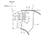
- FIG. 7 is a view showing the configuration of the wing 15 in the air conditioner according to the present embodiment.
- a notch group 39 including a plurality of notches 39 a, 39 b, 39 c, 39 d arranged in parallel in the axial direction is formed on the trailing edge 31 of the wing 15.
- Each of the notches 39a, 39b, 39c, 39d has the same shape as the notch 34 shown in FIG. 2 and FIG.
- the notches 39a, 39b, 39c, 39d are arranged in this order from the main plate 13 side to the side plate 14 side.
- a connection point at which the first side 35a of the notch 39a located closest to the main plate 13 among the notch group 39 and the rear edge 31 are connected is an end 40 of the notch group 39 on the main plate 13 side.
- a connection point at which the second side 35 b of the notch 39 d located closest to the side plate 14 in the notch group 39 and the rear edge 31 are connected is an end 41 of the notch group 39 on the side plate 14 side.
- an imaginary plane located at an intermediate position between the end 40 and the end 41 in the axial direction is taken as a third plane P3.
- the third plane P3 is located closer to the main plate 13 than the first plane P1.
- the third plane P3 is a plane perpendicular to the axial direction, and is a plane in which the distance from the end 40 and the distance from the end 41 are equal.
- the rear edge 31 is formed with the notch group 39 including the plurality of notches 39a, 39b, 39c, and 39d.
- a plane perpendicular to the axial center direction of the turbo fan 10 and having a distance from the main plate side end 31a equal to a distance from the side plate side end 31b is referred to as a first plane P1.
- the blade 15 is formed with the notch group 39 over a wide range near the main plate 13 in the axial direction. Therefore, an effect of bending the air flow direction to the side plate 14 side by the notches 39a, 39b, 39c, 39d can be obtained for the air flow passing through the wide range of the wing 15 in the axial direction. Therefore, it is possible to effectively reduce the deviation of the air volume distribution of the air flowing into the heat exchanger 20.
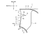
- FIG. 8 is a view showing the configuration of the wing 15 in the air conditioner according to the present embodiment.
- a plurality of recesses 42 aligned in the axial direction are formed in order to subdivide the trailing edge discharge vortex.
- the rear edge 31 closer to the side plate 14 than the notch 34 has a sawtooth shape.
- the recess 42 is not formed in the rear edge 31 closer to the main plate 13 than the notch 34. That is, the recess 42 is formed only on the side plate 14 side of the notch 34 in the rear edge 31. Further, the recess 42 is formed in the entire area of the rear edge 31 closer to the side plate 14 than the notch 34.
- the depth dimension D2 of the recess 42 in the radial direction is equal to or less than the width dimension W2 of the recess 42 in the axial direction (D2 ⁇ W2).
- the width dimension W2 of the recess 42 in the axial direction is smaller than the width dimension W1 (see FIG. 2) of the notch 34 (W2 ⁇ W1).
- the depth dimension D2 of the recessed part 42 in radial direction is smaller than the depth dimension D1 (refer FIG. 2) of the notch 34 (D2 ⁇ D1).
- the plurality of recessed portions 42 are formed on the side plate 14 side of the notch 34 in the rear edge 31.
- the width dimension W2 of each of the plurality of recesses 42 in the axial direction of the turbofan 10 is smaller than the width dimension W1 of the notch 34 in the axial direction.
- the depth dimension D2 of each of the plurality of recesses 42 in the radial direction of the turbofan 10 is smaller than the depth dimension D1 of the notch 34 in the radial direction.
- a plurality of recessed portions 42 are formed on the side plate 14 side of the trailing edge 31 than the notch 34, that is, the portion where the wind speed of air is relatively faster.
- the trailing edge discharge vortices released can be effectively subdivided. Therefore, the noise of the turbo fan 10 and the air conditioner can be reduced.
Landscapes
- Engineering & Computer Science (AREA)
- Mechanical Engineering (AREA)
- General Engineering & Computer Science (AREA)
- Chemical & Material Sciences (AREA)
- Combustion & Propulsion (AREA)
- Air-Conditioning Room Units, And Self-Contained Units In General (AREA)
- Structures Of Non-Positive Displacement Pumps (AREA)
Abstract
La présente invention concerne un climatiseur comprenant un turbo-ventilateur comportant une roue à aubes et un moteur de ventilateur, et un échangeur de chaleur disposé en aval de la roue à aubes. La roue à aubes comporte une plaque principale reliée à un arbre d'entraînement du moteur de ventilateur, une plaque latérale disposée en regard de la plaque principale et comportant une ouverture d'aspiration formée dans son centre, et une pluralité d'aubes agencées entre la plaque principale et la plaque latérale. La pluralité d'aubes comportent chacune un bord d'attaque et un bord de fuite disposé plus radialement vers l'extérieur par rapport au bord d'attaque. Une entaille est formée dans le bord de fuite. La pluralité d'aubes comportent chacune, en tant que paire de côtés se faisant face sur toute l'étendue de l'entaille, un premier côté positionné du côté plaque principale de l'entaille et un second côté positionné du côté plaque latérale de l'entaille. Le second côté est formé de façon à être convexe vers le côté plaque principale.
Priority Applications (6)
| Application Number | Priority Date | Filing Date | Title |
|---|---|---|---|
| ES17919054T ES2892967T3 (es) | 2017-07-26 | 2017-07-26 | Acondicionador de aire |
| EP17919054.1A EP3660405B1 (fr) | 2017-07-26 | 2017-07-26 | Climatiseur |
| JP2019532267A JP6710337B2 (ja) | 2017-07-26 | 2017-07-26 | 空気調和機 |
| CN201780092958.XA CN110892201B (zh) | 2017-07-26 | 2017-07-26 | 空气调节机 |
| PCT/JP2017/027052 WO2019021391A1 (fr) | 2017-07-26 | 2017-07-26 | Climatiseur |
| TW106133107A TWI664381B (zh) | 2017-07-26 | 2017-09-27 | 空氣調節機 |
Applications Claiming Priority (1)
| Application Number | Priority Date | Filing Date | Title |
|---|---|---|---|
| PCT/JP2017/027052 WO2019021391A1 (fr) | 2017-07-26 | 2017-07-26 | Climatiseur |
Publications (1)
| Publication Number | Publication Date |
|---|---|
| WO2019021391A1 true WO2019021391A1 (fr) | 2019-01-31 |
Family
ID=65040984
Family Applications (1)
| Application Number | Title | Priority Date | Filing Date |
|---|---|---|---|
| PCT/JP2017/027052 Ceased WO2019021391A1 (fr) | 2017-07-26 | 2017-07-26 | Climatiseur |
Country Status (6)
| Country | Link |
|---|---|
| EP (1) | EP3660405B1 (fr) |
| JP (1) | JP6710337B2 (fr) |
| CN (1) | CN110892201B (fr) |
| ES (1) | ES2892967T3 (fr) |
| TW (1) | TWI664381B (fr) |
| WO (1) | WO2019021391A1 (fr) |
Families Citing this family (2)
| Publication number | Priority date | Publication date | Assignee | Title |
|---|---|---|---|---|
| KR20220033358A (ko) * | 2020-09-09 | 2022-03-16 | 삼성전자주식회사 | 팬, 팬을 갖는 공기조화기 및 팬의 제조방법 |
| DE102024123702B3 (de) * | 2024-08-20 | 2025-11-13 | Ebm-Papst Mulfingen Gmbh & Co. Kg | Laufrad für einen Ventilator |
Citations (5)
| Publication number | Priority date | Publication date | Assignee | Title |
|---|---|---|---|---|
| JPH10132310A (ja) * | 1996-10-28 | 1998-05-22 | Daikin Ind Ltd | 遠心ファン及びこの遠心ファンを備えた空気調和機 |
| JP3092554B2 (ja) | 1997-09-30 | 2000-09-25 | ダイキン工業株式会社 | 遠心送風機及びその製造方法並びに該遠心送風機を備えた空気調和機 |
| WO2011121943A1 (fr) * | 2010-03-29 | 2011-10-06 | 三菱電機株式会社 | Turbosoufflante et climatiseur d'intérieur équipé de celle-ci |
| JP2011226448A (ja) * | 2010-04-23 | 2011-11-10 | Toshiba Carrier Corp | 遠心ファン及び空気調和機 |
| JP2013096378A (ja) * | 2011-11-04 | 2013-05-20 | Daikin Industries Ltd | 遠心送風機 |
Family Cites Families (7)
| Publication number | Priority date | Publication date | Assignee | Title |
|---|---|---|---|---|
| KR100782195B1 (ko) * | 2006-08-10 | 2007-12-04 | 엘지전자 주식회사 | 공기 조화기 |
| EP2264320B1 (fr) * | 2008-04-18 | 2018-08-08 | Mitsubishi Electric Corporation | Turboventilateur et climatiseur |
| JP4994421B2 (ja) * | 2009-05-08 | 2012-08-08 | 三菱電機株式会社 | 遠心ファン及び空気調和機 |
| US9528374B2 (en) * | 2011-04-12 | 2016-12-27 | Mitsubishi Electric Corporation | Turbofan, and air-conditioning apparatus |
| DE202012103554U1 (de) * | 2012-09-18 | 2013-12-20 | Ebm-Papst Mulfingen Gmbh & Co. Kg | Laufrad mit Wuchtausgleich |
| EP3399195B1 (fr) * | 2015-12-28 | 2020-02-19 | Daikin Industries, Ltd. | Procédé pour la fabrication d' une hélice pour ventilateur centrifuge et dispositif pour la fabrication de celle-ci |
| CN106979163A (zh) * | 2016-01-15 | 2017-07-25 | 台湾樱花股份有限公司 | 抽油烟机低噪音风扇结构 |
-
2017
- 2017-07-26 ES ES17919054T patent/ES2892967T3/es active Active
- 2017-07-26 JP JP2019532267A patent/JP6710337B2/ja active Active
- 2017-07-26 EP EP17919054.1A patent/EP3660405B1/fr active Active
- 2017-07-26 CN CN201780092958.XA patent/CN110892201B/zh not_active Expired - Fee Related
- 2017-07-26 WO PCT/JP2017/027052 patent/WO2019021391A1/fr not_active Ceased
- 2017-09-27 TW TW106133107A patent/TWI664381B/zh not_active IP Right Cessation
Patent Citations (5)
| Publication number | Priority date | Publication date | Assignee | Title |
|---|---|---|---|---|
| JPH10132310A (ja) * | 1996-10-28 | 1998-05-22 | Daikin Ind Ltd | 遠心ファン及びこの遠心ファンを備えた空気調和機 |
| JP3092554B2 (ja) | 1997-09-30 | 2000-09-25 | ダイキン工業株式会社 | 遠心送風機及びその製造方法並びに該遠心送風機を備えた空気調和機 |
| WO2011121943A1 (fr) * | 2010-03-29 | 2011-10-06 | 三菱電機株式会社 | Turbosoufflante et climatiseur d'intérieur équipé de celle-ci |
| JP2011226448A (ja) * | 2010-04-23 | 2011-11-10 | Toshiba Carrier Corp | 遠心ファン及び空気調和機 |
| JP2013096378A (ja) * | 2011-11-04 | 2013-05-20 | Daikin Industries Ltd | 遠心送風機 |
Non-Patent Citations (1)
| Title |
|---|
| See also references of EP3660405A4 |
Also Published As
| Publication number | Publication date |
|---|---|
| ES2892967T3 (es) | 2022-02-07 |
| CN110892201B (zh) | 2021-05-11 |
| JP6710337B2 (ja) | 2020-06-17 |
| EP3660405A1 (fr) | 2020-06-03 |
| TW201910693A (zh) | 2019-03-16 |
| TWI664381B (zh) | 2019-07-01 |
| JPWO2019021391A1 (ja) | 2019-11-07 |
| CN110892201A (zh) | 2020-03-17 |
| EP3660405B1 (fr) | 2021-09-08 |
| EP3660405A4 (fr) | 2020-11-11 |
Similar Documents
| Publication | Publication Date | Title |
|---|---|---|
| EP1933039A1 (fr) | Ventilateur centrifuge et climatiseur associé | |
| CN102422025B (zh) | 离心风扇及空调机 | |
| KR101347932B1 (ko) | 관류 팬, 성형용 금형 및 유체 이송 장치 | |
| WO2014080494A1 (fr) | Climatiseur | |
| CN103403355A (zh) | 贯流风扇、成型用模具和流体输送装置 | |
| KR101788008B1 (ko) | 원심팬 및 그를 갖는 공기조화기 | |
| JP7062139B2 (ja) | 軸流ファン、送風装置、及び、冷凍サイクル装置 | |
| JP5079063B2 (ja) | プロペラおよび送風機並びにヒートポンプ装置 | |
| JP6811866B2 (ja) | プロペラファン、送風装置、及び冷凍サイクル装置 | |
| JP6945739B2 (ja) | 多翼送風機及び空気調和装置 | |
| JP2011179331A (ja) | 送風機とその送風機を用いた空気調和機 | |
| JP6710337B2 (ja) | 空気調和機 | |
| KR20180047646A (ko) | 공기조화기 | |
| JP7378611B2 (ja) | 軸流ファン、送風装置、及び、冷凍サイクル装置 | |
| JP7258136B2 (ja) | 軸流ファン、送風装置、及び、冷凍サイクル装置 | |
| JP7275312B2 (ja) | 軸流ファン、送風装置、及び、冷凍サイクル装置 | |
| JP7241667B2 (ja) | プロペラファン | |
| WO2023084652A1 (fr) | Ventilateur à flux transversal, dispositif de soufflage et dispositif à cycle de réfrigération | |
| CN109891101B (zh) | 螺旋桨风扇、室外机和制冷循环装置 | |
| WO2014207908A1 (fr) | Unité d'intérieur pour dispositif de climatisation | |
| WO2024214327A1 (fr) | Soufflante centrifuge, machine de climatisation et dispositif à cycle de réfrigération | |
| WO2018002987A1 (fr) | Ventilateur multi-pales et climatiseur | |
| WO2024089808A1 (fr) | Ventilateur à écoulement axial, souffleuse d'air et dispositif de conditionnement d'air | |
| JP6692456B2 (ja) | プロペラファン及び空気調和装置の室外機 | |
| WO2023112077A1 (fr) | Ventilateur axial, soufflante et dispositif à cycle frigorifique |
Legal Events
| Date | Code | Title | Description |
|---|---|---|---|
| 121 | Ep: the epo has been informed by wipo that ep was designated in this application |
Ref document number: 17919054 Country of ref document: EP Kind code of ref document: A1 |
|
| ENP | Entry into the national phase |
Ref document number: 2019532267 Country of ref document: JP Kind code of ref document: A |
|
| NENP | Non-entry into the national phase |
Ref country code: DE |
|
| ENP | Entry into the national phase |
Ref document number: 2017919054 Country of ref document: EP Effective date: 20200226 |