WO2024214327A1 - Soufflante centrifuge, machine de climatisation et dispositif à cycle de réfrigération - Google Patents
Soufflante centrifuge, machine de climatisation et dispositif à cycle de réfrigération Download PDFInfo
- Publication number
- WO2024214327A1 WO2024214327A1 PCT/JP2023/040772 JP2023040772W WO2024214327A1 WO 2024214327 A1 WO2024214327 A1 WO 2024214327A1 JP 2023040772 W JP2023040772 W JP 2023040772W WO 2024214327 A1 WO2024214327 A1 WO 2024214327A1
- Authority
- WO
- WIPO (PCT)
- Prior art keywords
- fan
- centrifugal blower
- blades
- suction port
- diameter
- Prior art date
- Legal status (The legal status is an assumption and is not a legal conclusion. Google has not performed a legal analysis and makes no representation as to the accuracy of the status listed.)
- Ceased
Links
Images







Classifications
-
- F—MECHANICAL ENGINEERING; LIGHTING; HEATING; WEAPONS; BLASTING
- F04—POSITIVE - DISPLACEMENT MACHINES FOR LIQUIDS; PUMPS FOR LIQUIDS OR ELASTIC FLUIDS
- F04D—NON-POSITIVE-DISPLACEMENT PUMPS
- F04D17/00—Radial-flow pumps, e.g. centrifugal pumps; Helico-centrifugal pumps
- F04D17/08—Centrifugal pumps
- F04D17/10—Centrifugal pumps for compressing or evacuating
-
- F—MECHANICAL ENGINEERING; LIGHTING; HEATING; WEAPONS; BLASTING
- F04—POSITIVE - DISPLACEMENT MACHINES FOR LIQUIDS; PUMPS FOR LIQUIDS OR ELASTIC FLUIDS
- F04D—NON-POSITIVE-DISPLACEMENT PUMPS
- F04D29/00—Details, component parts, or accessories
- F04D29/26—Rotors specially for elastic fluids
- F04D29/28—Rotors specially for elastic fluids for centrifugal or helico-centrifugal pumps for radial-flow or helico-centrifugal pumps
- F04D29/30—Vanes
Definitions
- This disclosure relates to centrifugal blowers, air conditioners, and refrigeration cycle devices.
- the present disclosure has been made to solve these problems. Its purpose is to provide a double-suction type centrifugal blower in which the motor is located on one side and which can prevent imbalances in both the suction air volume and the blowing speed between the side closer to the motor and the opposite side, as well as an air conditioner and a refrigeration cycle device equipped with such a centrifugal blower.
- the centrifugal blower is a double-intake centrifugal blower including a fan having a plurality of blades arranged in a circumferential direction around a rotation axis, a scroll casing in which a first suction port, a second suction port, and a discharge port are formed and in which the fan is disposed, and a motor provided on the first suction port side of the scroll casing and rotates the fan around the rotation axis, the fan including a disk-shaped main plate, the plurality of blades including a plurality of first blades provided on the surface of the main plate on the first suction port side and a plurality of second blades provided on the surface of the main plate on the second suction port side, and the first fan diameter from the rotation axis to the outer circumferential ends of the plurality of first blades is different from the second fan diameter from the rotation axis to the outer circumferential ends of the plurality of second blades.
- the air conditioner disclosed herein comprises a centrifugal blower configured as described above, and a heat exchanger that exchanges heat between the air supplied by the centrifugal blower and the refrigerant flowing inside.
- the refrigeration cycle device includes a centrifugal blower configured as described above, a condenser that condenses the refrigerant, and an evaporator that evaporates the refrigerant, and the centrifugal blower blows air around one or both of the condenser and the evaporator.
- centrifugal blower, air conditioner, and refrigeration cycle device disclosed herein have the advantage that in a double-suction centrifugal blower in which the motor is located on one side, imbalances in both the suction air volume and the blowing speed between the side closer to the motor and the opposite side can be suppressed.
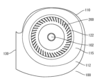
- FIG. 1 is a front view of a centrifugal blower according to a first embodiment.
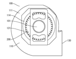
- FIG. 2 is a rear view of the centrifugal blower according to the first embodiment.
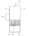
- FIG. 1 is a side view of a centrifugal blower according to a first embodiment.
- FIG. 2 is a perspective view of a fan of the centrifugal blower according to the first embodiment.
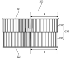
- FIG. 2 is a side view of a fan of the centrifugal blower according to the first embodiment.
- FIG. 11 is a side view of a modified example of the fan of the centrifugal blower according to the first embodiment.
- 1 is a cross-sectional view of a centrifugal blower according to a first embodiment.
- FIG. 2 is an enlarged cross-sectional view showing a main part of the centrifugal blower according to the first embodiment.
- FIG. FIG. 11 is a front view of a scroll casing in a modified example of the centrifugal blower according to the first embodiment.
- FIG. 11 is a side view of a scroll casing in a modified example of the centrifugal blower according to the first embodiment.
- FIG. 4 is a plan view of a fan in a first modification of the centrifugal blower according to the first embodiment.
- FIG. 4 is a plan view of a fan in a first modification of the centrifugal blower according to the first embodiment.
- FIG. 11 is a plan view of a fan in a second modified example of the centrifugal blower according to embodiment 1.
- FIG. 11 is a plan view of a fan in a second modified example of the centrifugal blower according to embodiment 1.
- FIG. 11 is a plan view of a fan in a third modified example of the centrifugal blower according to embodiment 1.
- FIG. 11 is a plan view of a fan in a third modified example of the centrifugal blower according to embodiment 1.
- FIG. 13 is a plan view of a fan in a fourth modified example of the centrifugal blower according to embodiment 1.
- FIG. 13 is a plan view of a fan in a fourth modified example of the centrifugal blower according to embodiment 1.
- FIG. 11 is a perspective view of a fan in a modified example of the centrifugal blower according to the first embodiment.
- FIG. 11 is a perspective view of a fan in a modified example of the centrifugal blower according to the first embodiment.
- 1 is a diagram showing the configuration of an air conditioner equipped with a centrifugal blower according to a first embodiment
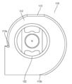
- Fig. 1 is a front view of a centrifugal blower.
- Fig. 2 is a rear view of the centrifugal blower.
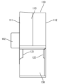
- Fig. 3 is a side view of the centrifugal blower.
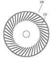
- Fig. 4 is a perspective view of a fan of the centrifugal blower.
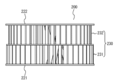
- Fig. 5 is a side view of the fan of the centrifugal blower.
- Fig. 6 is a side view of a modified version of the fan of the centrifugal blower.
- Fig. 7 is a cross-sectional view of the centrifugal blower.
- Fig. 1 is a front view of a centrifugal blower.
- Fig. 2 is a rear view of the centrifugal blower.
- Fig. 3 is a side view of the centrifugal blower.
- Fig. 4 is a perspective view of a fan of the centrifugal blower.
- Fig. 5 is a side view of
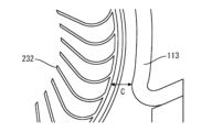
- Fig. 8 is a cross-sectional view showing an enlarged main part of the centrifugal blower.
- Fig. 9 is a front view of a scroll casing in a modified version of the centrifugal blower.
- Fig. 10 is a side view of a scroll casing in a modified version of the centrifugal blower.
- Figs. 11 and 12 are plan views of a fan in a first modified example of the centrifugal blower.
- Figs. 13 and 14 are plan views of a fan in a second modified example of the centrifugal blower.
- Figs. 15 and 16 are plan views of a fan in a third modified example of the centrifugal blower.
- FIG. 18 are plan views of a fan in a fourth modified example of a centrifugal blower
- Fig. 19 and Fig. 20 are perspective views of a fan in a modified example of a centrifugal blower
- Fig. 21 is a diagram showing the configuration of an air conditioner equipped with a centrifugal blower.
- the blower 100 in this embodiment is a so-called double-suction centrifugal blower with suction ports formed on both sides. As shown in Figures 1 to 3, the blower 100 includes a fan 200, a scroll casing 110, a motor 101, and a shaft 102.
- the fan 200 is a centrifugal impeller that generates the airflow of the blower 100.
- the fan 200 is disposed inside the scroll casing 110.
- the fan 200 can rotate inside the scroll casing 110 around the shaft 102, which serves as the axis of rotation.
- the scroll casing 110 straightens the air blown out from the fan 200.
- the scroll casing 110 has a first side wall surface 111, a second side wall surface 112, and a peripheral wall surface 113.
- the first side wall surface 111 and the second side wall surface 112 are each arranged perpendicular to the rotation axis of the fan 200.
- the first side wall surface 111 and the second side wall surface 112 are provided on both sides of the fan 200 in the direction of the rotation axis of the fan 200. In other words, the first side wall surface 111 and the second side wall surface 112 are arranged on either side of the fan 200.
- the peripheral wall surface 113 is provided so as to surround the fan 200 from the radial outside of the fan 200.
- the peripheral wall surface 113 connects the first side wall surface 111 and the second side wall surface 112.
- the first side wall surface 111 and the second side wall surface 112 are arranged opposite each other via the peripheral wall surface 113.
- the peripheral wall surface 113 is arranged, for example, parallel to the rotation axis of the fan 200. Note that the peripheral wall surface 113 may be inclined with respect to the rotation axis of the fan 200, and is not limited to being arranged parallel to the rotation axis.
- a first suction port 121 is formed in the first side wall surface 111.
- a second suction port 122 is formed in the second side wall surface 112.
- Each of the first suction port 121 and the second suction port 122 has a circular shape centered on the rotation axis of the fan 200. Note that the shape of these suction ports is not limited to a circular shape, and may be other shapes, such as an elliptical shape.
- a first bell mouth 114 is formed on the outer periphery of the first suction port 121 on the first side wall surface 111.
- the first bell mouth 114 straightens the gas sucked into the fan 200 and causes it to flow into the first suction port 121.
- the second bell mouth 115 straightens the gas sucked into the fan 200 and causes it to flow into the second suction port 122.
- the first bell mouth 114 and the second bell mouth 115 are formed so that the opening diameter gradually becomes smaller from the outside to the inside of the scroll casing 110.
- the air near the first suction port 121 and the second suction port 122 flows smoothly along the first bell mouth 114 and the second bell mouth 115, and efficiently flows into the fan 200 from the first suction port 121 and the second suction port 122.
- the first bell mouth 114 and the second bell mouth 115 guide the air to the inside of the fan 200.
- the scroll casing 110 is formed with an outlet 130.
- the outlet 130 is an opening through which the airflow generated by the fan 200 within the scroll casing 110 is discharged.
- the opening shape of the outlet 130 is, for example, rectangular. However, the opening shape of the outlet 130 is not limited to a rectangular shape. In the illustrated example, the opening surface of the outlet 130 is arranged parallel to the rotation axis of the fan 200. However, the opening surface of the outlet 130 does not necessarily have to be parallel to the rotation axis of the fan 200.
- the peripheral wall surface 113 of the scroll casing 110 guides the airflow generated by the fan 200 along the curved wall surface to the discharge port 130.
- the peripheral wall surface 113 is formed into a curved surface that has a spiral shape when viewed from a direction parallel to the rotation axis of the fan 200. Examples of the spiral shape include a logarithmic spiral, an Archimedean spiral, or a spiral shape based on an involute curve. This allows the air sent out from the fan 200 to flow smoothly through the gap between the fan 200 and the peripheral wall in the direction of the discharge port 130. Therefore, inside the scroll casing 110, the static pressure of the air increases efficiently toward the discharge port 130.
- the scroll casing 110 has a discharge section that guides the airflow generated by the rotating fan 200 to the discharge port 130.
- One side of the peripheral wall of the discharge section is smoothly continuous with the end of the spiral shape described above.
- the other side of the peripheral wall of the discharge section is connected via a tongue portion to the beginning of the spiral shape described above.
- the tongue portion is a convex portion that bulges into the inside of the scroll casing 110.
- Blower 100 configured as described above is a double-suction centrifugal blower that draws in air from both ends of the rotating shaft of blower 100 and blows air out from outlet 130.
- the motor 101 of the blower 100 is disposed on the first side wall surface 111 side of the scroll casing 110.
- the shaft 102 transmits the rotational driving force of the motor 101 to the fan 200.
- the fan 200 comprises a main plate 210, a first side plate 221, a second side plate 222, and a plurality of blades 230.
- the main plate 210 is a disk-shaped member.
- the shaft 102 is fixed to the center of the main plate 210.
- the plurality of blades 230 are arranged radially in the circumferential direction of the main plate 210 on both sides of the main plate 210.
- the plurality of blades 230 are arranged in the circumferential direction centered on the rotation axis of the fan 200.
- the plurality of blades 230 are arranged at regular intervals from each other in the circumferential direction of the main plate 210.
- the multiple blades 230 include multiple first blades 231 and multiple second blades 232.
- the multiple first blades 231 are provided on the surface of the main plate 210 facing the first side wall surface 111, i.e., the surface facing the first suction port 121.
- the multiple second blades 232 are provided on the surface of the main plate 210 facing the second side wall surface 112, i.e., the surface facing the second suction port 122.
- the first side plate 221 is a circular plate-shaped member.
- the first side plate 221 is fixed to the ends of the multiple first wings 231 on the opposite side to the main plate 210 and on the outer circumferential side.
- the first side plate 221 maintains the positional relationship of the tips of each first blade 231 and reinforces the multiple first blades 231.
- one end of each first blade 231 is connected to the main plate 210 and the other end is connected to the first side plate 221. That is, each of the multiple first wings 231 is disposed between the main plate 210 and the first side plate 221.
- the second side plate 222 is an annular plate-shaped member.
- the second side plate 222 is fixed to the ends of the multiple second wings 232 on the opposite side to the main plate 210 and on the outer circumferential side.
- the second side plate 222 maintains the positional relationship of the tips of the second wings 232 and reinforces the multiple second wings 232.
- one end of each second wing 232 is connected to the main plate 210 and the other end is connected to the second side plate 222. That is, each of the multiple second wings 232 is disposed between the main plate 210 and the second side plate 222.
- the first fan diameter A and the second fan diameter B of the fan 200 are different.
- the first fan diameter A is the outer radius of the fan 200 on the first suction port 121 side, i.e., the distance from the rotation axis of the blower 100 to the outer peripheral ends of the multiple first blades 231.
- the second fan diameter B is the outer radius of the fan 200 on the second suction port 122 side, i.e., the distance from the rotation axis of the blower 100 to the outer peripheral ends of the multiple second blades 232.
- the first fan diameter A of the fan 200 is larger than the second fan diameter B. Therefore, the blade area of the first blade 231 is larger than the blade area of the second blade 232. In this case, the first blade 231 and the second blade 232 may or may not be similar in shape in the radial direction.
- the first fan diameter A on the side of the first suction port 121 where the motor 101 is located is made larger than the second fan diameter B on the side of the second suction port 122 where the motor 101 is not located, thereby making it possible to increase the amount of air on one side where the motor 101 is located and where it is difficult to suck in. Therefore, in a blower 100 with two suction sides where the motor 101 is provided on one side, it is possible to prevent imbalances in both the suction air volume and blowing speed between the side closer to the motor 101 and the opposite side.
- the inner diameter of the first side plate 221 may be larger than the inner diameter of the second side plate 222, and the outer diameter of the first side plate 221 may be equal to the outer diameter of the second side plate 222.
- the radial dimension of the first side plate 221 may be smaller than the radial dimension of the second side plate 222.
- the shortest distance C from the outer circumferential end of the fan 200 to the peripheral wall surface 113 of the scroll casing 110 may be set to 1% to 10% of the second fan diameter B (i.e., the smaller of the first fan diameter A and the second fan diameter B).
- the outer circumferential end of the fan 200 refers to the outer circumferential end of the side plate 220 or the outer circumferential end of the blade 230, whichever is located closer to the outer circumferential side.
- the outer circumferential end of the side plate 220 is the outer circumferential end of the fan 200.
- the distance from the outer circumferential end of the fan 200 to the peripheral wall surface 113 of the scroll casing 110 is the shortest at the tongue portion described above. Therefore, in other words, the distance C from the outer circumferential end of the fan 200 to the tongue portion of the scroll casing 110 may be set to 1% to 10% of the second fan diameter B. By doing so, it is possible to suppress airflow leakage, especially at the tongue portion.
- the scroll casing 110 may be radially enlarged on the first suction port 121 side of the main plate 210 of the fan 200 compared to the second suction port 122 side of the main plate 210 of the fan 200.
- the first suction port 121 side of the main plate 210 of the fan 200 in the scroll casing 110 refers to the portion on the first suction port 121 side based on the position of the peripheral wall surface 113 facing the main plate 210.
- the second suction port 122 side of the main plate 210 of the fan 200 in the scroll casing 110 refers to the portion on the second suction port 122 side based on the position of the peripheral wall surface 113 facing the main plate 210.
- the side of the scroll casing 110 closer to the first suction port 121 than the main plate 210 of the fan 200 is also simply referred to as the "first suction port 121 side of the scroll casing 110.”
- the side of the scroll casing 110 closer to the second suction port 122 than the main plate 210 of the fan 200 is also simply referred to as the "second suction port 122 side of the scroll casing 110.”
- the first suction port 121 side of the scroll casing 110 may be gradually expanded in the radial direction toward the first suction port 121 side, i.e., toward the first side wall surface 111.
- the entire first suction port 121 side of the scroll casing 110 may be expanded in the radial direction compared to the second suction port 122 side of the scroll casing 110.
- the first suction port 121 side of the scroll casing 110 is expanded in the radial direction.
- the part of the scroll casing 110 other than the discharge portion is the scroll portion.
- the peripheral wall surface 113 has the spiral shape described above. Therefore, the start portion 113a of the spiral shape can be rephrased as the start portion 113a of the scroll portion. Similarly, the end portion 113b of the spiral shape can be rephrased as the end portion 113b of the scroll portion.
- the air path is widened and the increased air speed can be reduced.
- the concentration of airflow near the first side plate 221 can be eliminated.
- the first fan diameter A on the first blade 231 side i.e., the first suction port 121 side where the motor 101 is located
- the second fan diameter B on the second blade 232 side i.e., the second suction port 122 side where the motor 101 is not located.
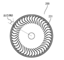
- Fig. 11 is a view of the fan 200 from the first blade 231 side
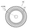
- Fig. 12 is a view of the fan 200 from the second blade 232 side.
- the outlet angle D of the first blades 231 is larger than the outlet angle E of the second blades 232.
- the outlet angle is the angle formed by the line connecting the center of the fan 200 and the outer circumferential end (trailing end) of the blade 230 and the center line of the blade 230 at the outer circumferential end (trailing end) of the blade 230.
- the first fan diameter A on the first blade 231 side is smaller than the second fan diameter B on the second blade 232 side.
- the speed of the airflow passing through the first blade 231 increases. This increases the amount of air passing through the first suction port 121 per unit time, and suppresses the occurrence of an imbalance in the amount of air intake between the side closer to the motor 101 and the opposite side.
- the first fan diameter A on the first blade 231 side smaller than the second fan diameter B on the second blade 232 side, the distance between the outer circumferential end of the first blade 231 and the peripheral wall surface 113 of the scroll casing 110 can be increased, and the speed of the airflow blown out from the first blade 231 side can be reduced.
- the increase in the blowing speed due to the increase in the outlet angle is offset by the reduction in the fan diameter, and the speed of the airflow blown out from the discharge port 130 can finally be balanced. Therefore, in a blower 100 with two suction sides and a motor 101 on one side, it is possible to prevent imbalances in both the suction air volume and the blowing speed between the side closer to the motor 101 and the opposite side.
- Fig. 13 is a view of the fan 200 from the first blade 231 side
- Fig. 14 is a view of the fan 200 from the second blade 232 side.
- the stagger angle F of the first blades 231 is smaller than the stagger angle G of the second blades 232.
- the stagger angle is the angle formed by a line connecting the center of the fan 200 and the inner circumferential end (leading edge) of the blade 230, and a line connecting the inner circumferential end (leading edge) of the blade 230 and the outer circumferential end (trailing edge) of the blade 230.
- the first fan diameter A on the first blade 231 side is smaller than the second fan diameter B on the second blade 232 side.
- the speed of the airflow passing through the first blade 231 increases. This increases the amount of air passing through the first suction port 121 per unit time, and suppresses the occurrence of an imbalance in the amount of air suction between the side closer to the motor 101 and the opposite side.
- the first fan diameter A on the first blade 231 side smaller than the second fan diameter B on the second blade 232 side, the distance between the outer circumferential end of the first blade 231 and the circumferential wall surface 113 of the scroll casing 110 can be increased, and the speed of the airflow blown out from the first blade 231 side can be reduced.
- the increase in the blowing speed due to the reduction in the stagger angle is offset by the reduction in the fan diameter, and the speed of the airflow blown out from the discharge port 130 can finally be balanced. Therefore, in a blower 100 with two suction sides and a motor 101 on one side, it is possible to prevent imbalances in both the suction air volume and the blowing speed between the side closer to the motor 101 and the opposite side.
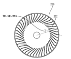
- Fig. 15 is a view of the fan 200 from the first blade 231 side
- Fig. 16 is a view of the fan 200 from the second blade 232 side.
- the inlet angle H of the first blades 231 is larger than the inlet angle I of the second blades 232.
- the inlet angle is the angle formed by the line connecting the center of the fan 200 and the inner circumferential end (leading edge end) of the blade 230 and the center line of the blade 230 at the inner circumferential end (leading edge end) of the blade 230.
- the first fan diameter A on the first blade 231 side is smaller than the second fan diameter B on the second blade 232 side.
- the speed of the airflow passing through the first blade 231 increases. This increases the amount of air passing through the first suction port 121 per unit time, and suppresses the occurrence of an imbalance in the amount of air intake between the side close to the motor 101 and the opposite side.
- the first fan diameter A on the first blade 231 side smaller than the second fan diameter B on the second blade 232 side, the distance between the outer circumferential end of the first blade 231 and the peripheral wall surface 113 of the scroll casing 110 can be increased, and the speed of the airflow blown out from the first blade 231 side can be reduced.
- the increase in the blowing speed due to the increase in the inlet angle is offset by the reduction in the fan diameter, and the speed of the airflow blown out from the discharge port 130 can finally be balanced. Therefore, in a blower 100 with two suction sides and a motor 101 on one side, it is possible to prevent imbalances in both the suction air volume and the blowing speed between the side closer to the motor 101 and the opposite side.
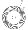
- Figure 17 is a view of the fan 200 seen from the first blade 231 side
- Figure 18 is a view of the fan 200 seen from the second blade 232 side.
- the number of first blades 231 on the side where the motor 101 is provided is greater than the number of second blades 232 on the side where the motor 101 is not provided.
- the first fan diameter A on the first blade 231 side is made smaller than the second fan diameter B on the second blade 232 side.
- the amount of air passing through the first suction port 121 per unit time can be increased, and the imbalance of the suction air volume between the side close to the motor 101 and the opposite side can be suppressed.
- the first fan diameter A on the first blade 231 side smaller than the second fan diameter B on the second blade 232 side, the distance between the outer circumferential end of the first blade 231 and the peripheral wall surface 113 of the scroll casing 110 can be increased, and the speed of the airflow blown out from the first blade 231 side can be reduced.
- the increase in the blowing speed due to the increase in the number of blades 230 is offset by the reduction in the fan diameter, and the speed of the airflow blown out from the discharge port 130 can be balanced. Therefore, in a blower 100 with two suction sides and a motor 101 on one side, it is possible to prevent imbalances between the side close to the motor 101 and the opposite side in terms of both the suction air volume and the blowing speed.
- the radial dimension of the first side plate 221 may be larger than the radial dimension of the second side plate 222.
- the inner diameter of the first side plate 221 may be smaller than the inner diameter of the second side plate 222
- the outer diameter of the first side plate 221 may be equal to the outer diameter of the second side plate 222.
- the second suction port 122 side of the scroll casing 110 may be expanded in the radial direction compared to the first suction port 121 side of the scroll casing 110.
- the second suction port 122 side of the scroll casing 110 may be gradually expanded in the radial direction as it approaches the second suction port 122 side.
- the entire second suction port 122 side of the scroll casing 110 may be expanded in the radial direction compared to the first suction port 121 side of the scroll casing 110.
- the second suction port 122 side of the scroll casing 110 in the radial direction in the range from the start of the scroll section 113a to the end of the scroll section 113b. In this way, by expanding the scroll casing 110 on the side with the larger fan diameter, the air path is widened and the increased air speed can be reduced.
- the blades 230 of the fan 200 on the side where the motor 101 is not present may be partly turbo blades.
- each of the multiple second blades 232 of the fan 200 may have a turbo blade 233 and a sirocco blade 234.
- the turbo blade 233 is provided on the inner side of the sirocco blade 234 in the radial direction centered on the rotation axis of the fan 200.
- the sirocco blade 234 is provided on the outer side of the turbo blade 233 in the radial direction centered on the rotation axis of the fan 200.
- the turbo blade 233 constitutes a backward blade with an outlet angle of 90 degrees or less.
- the sirocco blade 234 constitutes a forward blade with an outlet angle of more than 90 degrees.
- the blades 230 of the fan 200 on the side where the motor 101 is located may be only the sirocco blade portion.
- the first blades 231 of the fan 200 may not have the turbo blade portion 233, and may be only the sirocco blade portion 234.
- the first blade 231 on the side of the first suction port 121 where the motor 101 is located can be made into a sirocco blade, and the amount of air on the side where it is difficult to suck in can be increased.
- the second blade 232 on the side of the second suction port 122 where the motor 101 is not located can be made to have a turbo blade portion 233, which can suppress separation of the airflow from the blade and improve efficiency.
- the first fan diameter A on the first blade 231 side and the second fan diameter B on the second blade 232 side may be equal, or the first fan diameter A on the first blade 231 side may be larger than the second fan diameter B on the second blade 232 side.
- the exit angle, stagger angle, entrance angle, and number of the first blade 231 may be equal to the exit angle, stagger angle, entrance angle, and number of the second blades 232.
- the shortest distance C from the outer peripheral end of the fan 200 to the peripheral wall surface 113 of the scroll casing 110 should be set to the smaller of the first fan diameter A and the second fan diameter B, i.e., 1% to 10% of the first fan diameter A.
- the distance C from the outer peripheral end of the fan 200 to the tongue of the scroll casing 110 should be set to 1% to 10% of the first fan diameter A.
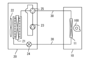
- FIG. 21 The configuration of an air conditioner equipped with a centrifugal blower according to the present disclosure is shown in FIG. 21.
- the air conditioner comprises an indoor unit 10 and an outdoor unit 20.
- the indoor unit 10 is installed inside the room to be air-conditioned, i.e., inside the room.
- the outdoor unit 20 is installed outside the room, i.e., outside the room.
- the indoor unit 10 comprises an indoor unit heat exchanger 11 and a blower 100.
- the outdoor unit 20 comprises an outdoor unit heat exchanger 21, an outdoor unit fan 200, a compressor 23, an expansion valve 24, and a four-way valve 25.
- the indoor unit 10 and the outdoor unit 20 are connected by a refrigerant pipe 30.
- the refrigerant pipe 30 is provided in a circulating manner between the indoor unit heat exchanger 11 of the indoor unit 10 and the outdoor unit heat exchanger 21 of the outdoor unit 20.
- a refrigerant is sealed in the refrigerant pipe 30.
- the refrigerant sealed in the refrigerant pipe 30 is, for example, difluoromethane (CH2F2:R32), etc.
- the refrigerant piping 30 connects the indoor unit heat exchanger 11, the four-way valve 25, the compressor 23, the outdoor unit heat exchanger 21, and the expansion valve 24 in a ring shape. Therefore, a refrigerant circuit is formed in which the refrigerant circulates between the indoor unit heat exchanger 11 and the outdoor unit heat exchanger 21.
- the compressor 23 is a device that compresses the supplied refrigerant to increase the pressure and temperature of the refrigerant.
- the compressor 23 may be, for example, a rotary compressor, a scroll compressor, or a reciprocating compressor.
- the expansion valve 24 expands the refrigerant condensed in the outdoor unit heat exchanger 21, reducing the pressure of the refrigerant.
- the indoor unit heat exchanger 11 exchanges heat between the refrigerant that has flowed into the indoor unit heat exchanger 11 and the air surrounding the indoor unit heat exchanger 11.
- the blower 100 blows indoor air so that it passes around the indoor unit heat exchanger 11, promoting heat exchange between the refrigerant and the air in the indoor unit heat exchanger 11, and sends the air that has been heated or cooled by the heat exchange back into the room.
- the outdoor unit heat exchanger 21 exchanges heat between the refrigerant that has flowed into the outdoor unit heat exchanger 21 and the air surrounding the outdoor unit heat exchanger 21.
- the outdoor unit fan 200 blows outdoor air so that it passes around the outdoor unit heat exchanger 21, promoting heat exchange between the refrigerant and the air in the outdoor unit heat exchanger 21.
- the refrigerant circuit configured in this manner works as a heat pump that transfers heat between the indoor unit 10 and the outdoor unit 20 by exchanging heat between the refrigerant and air in the indoor unit heat exchanger 11 and the outdoor unit heat exchanger 21.
- the four-way valve 25 the direction of circulation of the refrigerant in the refrigerant circuit can be reversed, allowing the air conditioner to switch between cooling operation and heating operation.
- the air conditioner configured as described above includes an indoor unit heat exchanger 11 that exchanges heat between the air supplied by the blower 100, which is a centrifugal blower, and the refrigerant flowing inside.
- the air conditioner also has the function of blowing air. Therefore, the air conditioner is also an example of a blower device that includes the blower 100 according to the present disclosure. Note that, although an example in which the blower 100 is applied to an indoor unit fan has been described above, the blower 100 may also be applied to an outdoor unit fan 200.
- the blower 100 may be used in refrigeration cycle devices other than air conditioners, such as showcases and chiller devices.
- the refrigeration cycle device includes the blower 100, which is a centrifugal blower, a condenser that condenses the refrigerant, and an evaporator that evaporates the refrigerant.
- the blower 100 blows air around one or both of the condenser and the evaporator.
- This disclosure can be used in double-suction centrifugal fans with a motor located on one side, as well as in air conditioners and refrigeration cycle devices equipped with such centrifugal fans.
Landscapes
- Engineering & Computer Science (AREA)
- Mechanical Engineering (AREA)
- General Engineering & Computer Science (AREA)
- Structures Of Non-Positive Displacement Pumps (AREA)
Abstract
Priority Applications (2)
| Application Number | Priority Date | Filing Date | Title |
|---|---|---|---|
| CN202380095493.9A CN120917236A (zh) | 2023-04-13 | 2023-11-13 | 离心送风机、空调机以及制冷循环装置 |
| TW113113032A TW202443033A (zh) | 2023-04-13 | 2024-04-08 | 離心送風機、空氣調合機及冷凍循環裝置 |
Applications Claiming Priority (2)
| Application Number | Priority Date | Filing Date | Title |
|---|---|---|---|
| JPPCT/JP2023/015024 | 2023-04-13 | ||
| PCT/JP2023/015024 WO2024214244A1 (fr) | 2023-04-13 | 2023-04-13 | Ventilateur centrifuge, appareil de climatisation et dispositif à cycle de réfrigération |
Publications (1)
| Publication Number | Publication Date |
|---|---|
| WO2024214327A1 true WO2024214327A1 (fr) | 2024-10-17 |
Family
ID=93058894
Family Applications (2)
| Application Number | Title | Priority Date | Filing Date |
|---|---|---|---|
| PCT/JP2023/015024 Ceased WO2024214244A1 (fr) | 2023-04-13 | 2023-04-13 | Ventilateur centrifuge, appareil de climatisation et dispositif à cycle de réfrigération |
| PCT/JP2023/040772 Ceased WO2024214327A1 (fr) | 2023-04-13 | 2023-11-13 | Soufflante centrifuge, machine de climatisation et dispositif à cycle de réfrigération |
Family Applications Before (1)
| Application Number | Title | Priority Date | Filing Date |
|---|---|---|---|
| PCT/JP2023/015024 Ceased WO2024214244A1 (fr) | 2023-04-13 | 2023-04-13 | Ventilateur centrifuge, appareil de climatisation et dispositif à cycle de réfrigération |
Country Status (3)
| Country | Link |
|---|---|
| CN (1) | CN120917236A (fr) |
| TW (1) | TW202443033A (fr) |
| WO (2) | WO2024214244A1 (fr) |
Citations (5)
| Publication number | Priority date | Publication date | Assignee | Title |
|---|---|---|---|---|
| JPS4963007A (fr) * | 1972-10-20 | 1974-06-19 | ||
| JPS6383667U (fr) * | 1986-11-20 | 1988-06-01 | ||
| JPH1071828A (ja) * | 1996-06-26 | 1998-03-17 | Denso Corp | 送風ユニット |
| US20200122551A1 (en) * | 2017-05-22 | 2020-04-23 | Hanon Systems | Blower unit of air conditioner for vehicle |
| WO2022113279A1 (fr) * | 2020-11-27 | 2022-06-02 | 三菱電機株式会社 | Dispositif de climatisation |
Family Cites Families (1)
| Publication number | Priority date | Publication date | Assignee | Title |
|---|---|---|---|---|
| JPS5887993U (ja) * | 1981-12-11 | 1983-06-15 | 株式会社デンソー | 送風機 |
-
2023
- 2023-04-13 WO PCT/JP2023/015024 patent/WO2024214244A1/fr not_active Ceased
- 2023-11-13 WO PCT/JP2023/040772 patent/WO2024214327A1/fr not_active Ceased
- 2023-11-13 CN CN202380095493.9A patent/CN120917236A/zh active Pending
-
2024
- 2024-04-08 TW TW113113032A patent/TW202443033A/zh unknown
Patent Citations (5)
| Publication number | Priority date | Publication date | Assignee | Title |
|---|---|---|---|---|
| JPS4963007A (fr) * | 1972-10-20 | 1974-06-19 | ||
| JPS6383667U (fr) * | 1986-11-20 | 1988-06-01 | ||
| JPH1071828A (ja) * | 1996-06-26 | 1998-03-17 | Denso Corp | 送風ユニット |
| US20200122551A1 (en) * | 2017-05-22 | 2020-04-23 | Hanon Systems | Blower unit of air conditioner for vehicle |
| WO2022113279A1 (fr) * | 2020-11-27 | 2022-06-02 | 三菱電機株式会社 | Dispositif de climatisation |
Also Published As
| Publication number | Publication date |
|---|---|
| CN120917236A (zh) | 2025-11-07 |
| TW202443033A (zh) | 2024-11-01 |
| WO2024214244A1 (fr) | 2024-10-17 |
Similar Documents
| Publication | Publication Date | Title |
|---|---|---|
| CN106468280B (zh) | 送风机以及具有该送风机的空气调节器 | |
| CN106481574B (zh) | 离心式风机和包括其的空调机 | |
| TW202004025A (zh) | 離心式送風機、送風裝置、空調裝置以及冷凍循環裝置 | |
| JP6035508B2 (ja) | 送風機とそれを用いた室外ユニット | |
| JPWO2020008519A1 (ja) | 多翼送風機及び空気調和装置 | |
| TW202316034A (zh) | 離心送風機、空氣調和裝置及冷凍循環裝置 | |
| JP7113819B2 (ja) | プロペラファン及び冷凍サイクル装置 | |
| JP7282215B2 (ja) | 送風機及び空気調和装置 | |
| JP7378611B2 (ja) | 軸流ファン、送風装置、及び、冷凍サイクル装置 | |
| TW202204773A (zh) | 遠心送風機的渦形殼體、具備這個渦形殼體的遠心送風機、空氣調和裝置以及冷凍循環裝置 | |
| WO2024214327A1 (fr) | Soufflante centrifuge, machine de climatisation et dispositif à cycle de réfrigération | |
| WO2023084652A1 (fr) | Ventilateur à flux transversal, dispositif de soufflage et dispositif à cycle de réfrigération | |
| WO2019021391A1 (fr) | Climatiseur | |
| WO2024214237A1 (fr) | Soufflante centrifuge, machine de climatisation et dispositif à cycle de réfrigération | |
| WO2024261928A1 (fr) | Ventilateur centrifuge, climatiseur et dispositif à cycle de réfrigération | |
| JP7378505B2 (ja) | 遠心送風機及びそれを備えた空気調和機 | |
| JP7466765B2 (ja) | 送風機、空気調和装置および冷凍サイクル装置 | |
| WO2023223383A1 (fr) | Ventilateur à flux transversal, dispositif de soufflage, et dispositif à cycle de réfrigération | |
| WO2024189889A1 (fr) | Unité intérieure pour climatiseur et climatiseur pourvu de celle-ci | |
| WO2024214236A1 (fr) | Unité intérieure de climatiseur et climatiseur équipé de celle-ci | |
| WO2026018317A1 (fr) | Soufflante | |
| WO2025017869A1 (fr) | Soufflante, dispositif de climatisation et dispositif à cycle de réfrigération | |
| WO2025150119A1 (fr) | Ventilateur centrifuge et climatiseur | |
| CN100532862C (zh) | 具有防逆流结构的离心扇导向部件 | |
| CN116507809A (zh) | 轴流风扇、送风装置以及制冷循环装置 |
Legal Events
| Date | Code | Title | Description |
|---|---|---|---|
| 121 | Ep: the epo has been informed by wipo that ep was designated in this application |
Ref document number: 23933101 Country of ref document: EP Kind code of ref document: A1 |
|
| WWE | Wipo information: entry into national phase |
Ref document number: 202380095493.9 Country of ref document: CN |
|
| WWP | Wipo information: published in national office |
Ref document number: 202380095493.9 Country of ref document: CN |
|
| NENP | Non-entry into the national phase |
Ref country code: DE |
|
| 122 | Ep: pct application non-entry in european phase |
Ref document number: 23933101 Country of ref document: EP Kind code of ref document: A1 |