WO2019021478A1 - Structure insonore, composant pour véhicule, et automobile - Google Patents
Structure insonore, composant pour véhicule, et automobile Download PDFInfo
- Publication number
- WO2019021478A1 WO2019021478A1 PCT/JP2017/027531 JP2017027531W WO2019021478A1 WO 2019021478 A1 WO2019021478 A1 WO 2019021478A1 JP 2017027531 W JP2017027531 W JP 2017027531W WO 2019021478 A1 WO2019021478 A1 WO 2019021478A1
- Authority
- WO
- WIPO (PCT)
- Prior art keywords
- layer
- soundproof structure
- absorbing member
- sound absorbing
- sound
- Prior art date
- Legal status (The legal status is an assumption and is not a legal conclusion. Google has not performed a legal analysis and makes no representation as to the accuracy of the status listed.)
- Ceased
Links
Images


Classifications
-
- B—PERFORMING OPERATIONS; TRANSPORTING
- B60—VEHICLES IN GENERAL
- B60R—VEHICLES, VEHICLE FITTINGS, OR VEHICLE PARTS, NOT OTHERWISE PROVIDED FOR
- B60R13/00—Elements for body-finishing, identifying, or decorating; Arrangements or adaptations for advertising purposes
- B60R13/08—Insulating elements, e.g. for sound insulation
-
- G—PHYSICS
- G10—MUSICAL INSTRUMENTS; ACOUSTICS
- G10K—SOUND-PRODUCING DEVICES; METHODS OR DEVICES FOR PROTECTING AGAINST, OR FOR DAMPING, NOISE OR OTHER ACOUSTIC WAVES IN GENERAL; ACOUSTICS NOT OTHERWISE PROVIDED FOR
- G10K11/00—Methods or devices for transmitting, conducting or directing sound in general; Methods or devices for protecting against, or for damping, noise or other acoustic waves in general
- G10K11/16—Methods or devices for protecting against, or for damping, noise or other acoustic waves in general
- G10K11/162—Selection of materials
- G10K11/168—Plural layers of different materials, e.g. sandwiches
-
- G—PHYSICS
- G10—MUSICAL INSTRUMENTS; ACOUSTICS
- G10K—SOUND-PRODUCING DEVICES; METHODS OR DEVICES FOR PROTECTING AGAINST, OR FOR DAMPING, NOISE OR OTHER ACOUSTIC WAVES IN GENERAL; ACOUSTICS NOT OTHERWISE PROVIDED FOR
- G10K11/00—Methods or devices for transmitting, conducting or directing sound in general; Methods or devices for protecting against, or for damping, noise or other acoustic waves in general
- G10K11/16—Methods or devices for protecting against, or for damping, noise or other acoustic waves in general
- G10K11/172—Methods or devices for protecting against, or for damping, noise or other acoustic waves in general using resonance effects
Definitions
- the present invention relates to a soundproof structure, parts for vehicles and automobiles.
- a vehicle such as a car is a machine that has a power source such as an engine and can be moved by human operation, and generates various vibrations and noises.
- the sounds transmitted to the inside of the vehicle include not only the sounds emitted by the power source but also the sounds generated outside the vehicle such as road noise, tire pattern noise and wind noise generated when the vehicle travels. .
- these sounds When these sounds are transmitted to the inside of the vehicle, they cause discomfort to people, so sound insulation and sound absorbing members are used in the engine, engine room, interior, body, exhaust pipe, etc. Measures have been taken.
- Patent Document 1 discloses a flexible porous foam molded by foam molding, an introduction passage opened on one surface, and a hollow portion formed at the back of the introduction passage and having a cross-sectional area larger than that of the introduction passage.
- a sound absorbing member is disclosed which has a large number of resonance chambers.
- Patent Document 2 discloses a sound / sound insulation structure including a resin molded body having a plurality of independent blind cavities having openings on the front or back and a sound absorbing member, and having a specific 100 Hz to 10 kHz resonant sound absorption peak frequency. It is done.
- the noise generated from the road surface during traveling such as tire pattern noise (in a frequency range of 500 to 3000 Hz and simply referred to as pattern noise) is less likely to be reflected and diffused around the lower part of the vehicle body, and the degree of sound intruding into the vehicle Is estimated to be high. Similar problems can occur with electric vehicles.
- the soundproof structure is achieved by arranging the opening of a member having an opening such as the sound absorbing member described in Patent Document 1 or the resin molded body described in Patent Document 2 to be opposed to a member constituting the vehicle. Noise can be absorbed by forming the body.
- the sound transmitted through the soundproof structure may be large, that is, the transmission loss of the soundproof structure may not be sufficiently large.
- the present invention has been made to solve the above-mentioned problems, and an object of the present invention is to provide a soundproof structure having a sufficiently large transmission loss.
- the present inventors found that the surface roughness of the surface of the introduction passage of the Helmholtz resonance structure affects the magnitude of the transmission loss of the soundproof structure. , Completed the present invention.
- the soundproof structure of the present invention comprises a sound absorbing member having a non-through hole; It is a soundproof structure which consists of a sound insulation material provided to be separated by a predetermined distance with an air layer opposed to the surface of the sound absorption member opened by the non-through hole.
- the non-through hole of the sound absorbing member has a Helmholtz resonance structure including an introduction passage opened on the surface and a hollow portion connected to the outside through the introduction passage,
- the surface roughness Ra of the introduction passage is characterized in that it is 0.1 to 100 ⁇ m.
- the surface roughness Ra of the introduction passage is 0.1 to 100 ⁇ m.
- the space between the sound insulation member and the sound absorbing member is a spring
- the air in the introduction passage is a mass portion
- the hollow portion is a spring.
- the surface roughness Ra of the introduction passage exceeds 100 ⁇ m, the range in which the air in the introduction passage can move becomes small, and the Helmholtz resonance mechanism due to the vibration of the air in the introduction passage becomes difficult to function. Therefore, the transmission loss is reduced.
- the surface roughness Ra of the introduction passage can be adjusted by the processing conditions of the introduction passage, polishing treatment, and roughening treatment such as sand blasting.
- the surface roughness Ra of the introduction passage is preferably 0.16 to 98 ⁇ m.
- the transmission loss can be increased.
- the surface roughness Ra of the introduction passage is preferably 1.02 to 98 ⁇ m.
- the introduction passage is preferably cylindrical. It is advantageous that the introduction passage has a cylindrical shape, because the soundproof property is not anisotropic.
- the sound absorbing member preferably includes an upper layer having a first through hole forming the introduction passage, and a lower layer having the hollow portion laminated on the upper layer.
- the sound absorbing member in the soundproof structure of the present invention can be easily manufactured by laminating the upper layer provided with the first through hole serving as the introduction passage and the lower layer having the hollow portion.
- the surface roughness of the introduction passage can be easily adjusted by separately manufacturing the upper layer and the lower layer.
- the lower layer of the sound absorbing member is formed of one layer, It is preferable that the upper layer and the lower layer be adhered by an adhesive layer.
- the adhesive is attached, the Helmholtz resonance structure is not easily deformed even when a compressive stress is applied, and the value of the surface roughness Ra of the introduction passage is hardly changed.
- the lower layer of the sound absorbing member is formed of one layer, It is preferable that a space be formed between the upper layer and the surface of the lower layer other than the hollow portion. Since the space exhibits the same effect as the unevenness of the inner wall of the introduction passage, the soundproof effect can be enhanced.
- the lower layer of the sound absorbing member is A side layer having a second through hole whose opening diameter is larger than that of the first through hole; It is preferable that the bottom layer in which the through holes are not formed be sequentially stacked, and the hollow portion be formed by the second through holes and the bottom layer. With such a configuration, the sound absorbing member in the soundproof structure of the present invention can be easily manufactured by sequentially laminating the upper layer, the side layer and the bottom layer.
- the upper layer and the side layer are preferably adhered by an adhesive layer.
- the adhesive is attached, the Helmholtz resonance structure is not easily deformed even when a compressive stress is applied, and the value of the surface roughness Ra of the introduction passage is hardly changed.
- a space is formed between the upper layer and a surface of the side surface layer other than the second through hole. Since the space exhibits the same effect as the unevenness of the inner wall of the introduction passage, the soundproof effect can be enhanced.
- the side layer and the bottom layer are preferably bonded by an adhesive layer.
- the adhesive is attached, the Helmholtz resonance structure is less likely to be deformed even when a compressive stress is applied, and the soundproof property is less likely to change due to the compressive deformation.
- a space is formed between the bottom layer and the surface other than the second through hole in the surface of the side layer. If a space is formed between the side surface layer and the bottom surface layer, the space acts as a vibrating spring and transmission loss can be further increased.
- the sound absorbing member is preferably made of a resin or a fibrous material.
- the resin is preferably an elastomer such as a foamed resin or rubber.
- the sound absorbing member is made of resin, weight reduction can be easily achieved, which is particularly desirable as a component for a vehicle.
- the resin is a foamed resin, the weight thereof can be made lighter, which can contribute to the improvement of the fuel efficiency when it is used as a component for a vehicle.
- the sound absorbing member may be a composite material of resin and fiber. As a method of compounding, resin and fiber may be mixed, resin and fiber may be combined in a block shape, and a plate of resin and fiber may be laminated.
- a fiber layer is further formed on the surface on the opening forming side of the sound absorbing member, It is preferable that an opening communicating with the opening of the introduction passage is formed in the fiber layer.
- the sound absorbing member has a Helmholtz resonance structure, it can absorb sound in a predetermined frequency range, but the width of the frequency range that can absorb sound is not wide, and in particular, it is difficult to sufficiently absorb sound in a high frequency range of 2000 Hz or more. .
- the fiber layer is formed, sound in a high frequency region of 2000 Hz or more can be absorbed.
- the sound insulation material is preferably a metal plate, and aluminum or a steel plate can be used, but a steel plate having a large specific gravity is preferable.
- the parts for vehicles of the present invention are characterized by including the soundproof structure of the present invention. Since the soundproof structure of the present invention is excellent in soundproofing performance, it is excellent as a component for a vehicle. As parts for vehicles provided with the soundproof structure of the present invention, a raising member, a partition member, a luggage box, etc. are mentioned.
- An automobile according to the present invention is characterized in that the soundproof structure according to the present invention is arranged with the above-mentioned sound insulation material directed to the road surface.
- FIG. 1 is a cross-sectional view schematically showing an example of the soundproof structure of the present invention.
- FIG. 2 is a cross-sectional view schematically showing another example of the soundproof structure of the present invention.
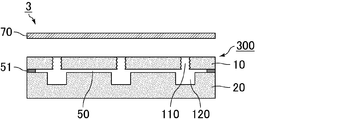
- FIG. 3 is a cross-sectional view schematically showing another example of the soundproof structure of the present invention.
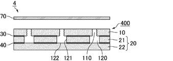
- FIG. 4 is a cross-sectional view schematically showing another example of the soundproof structure of the present invention.
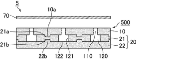
- FIG. 5 is a cross-sectional view schematically showing another example of the soundproof structure of the present invention.
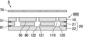
- FIG. 6 is a cross-sectional view schematically showing another example of the soundproof structure of the present invention.
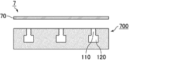
- FIG. 7 is a cross-sectional view schematically showing another example of the soundproof structure of the present invention.
- FIG.8 (a) is explanatory drawing which shows typically an example of the site
- FIG.8 (b) is a part of the area
- FIG. 9 is an explanatory view schematically showing an outline of a sound transmission loss test on the soundproof structure.
- FIGS. 10 (a), 10 (b) and 10 (c) are graphs showing the relationship between the frequency and the transmission loss in Examples 1, 2 and 3, respectively.
- FIGS. 11A and 11B are graphs showing the relationship between the frequency and the transmission loss in Comparative Examples 1 and 2, respectively.
- the soundproof structure according to the present invention comprises a sound absorbing member having a non-penetrating hole, and a sound insulating member provided opposite to a surface of the sound absorbing member with the non-penetrating hole open, with an air layer therebetween.
- the non-penetrating hole of the sound absorbing member has a Helmholtz resonance structure including an introduction passage opened on the surface and a hollow portion connected to the outside through the introduction passage.
- the surface roughness Ra of the introduction passage is 0.1 to 100 ⁇ m.
- the sound absorption member which comprises the soundproof structure of this invention is demonstrated.
- the sound absorbing member constituting the soundproof structure of the present invention is a member having a non-through hole, and the non-through hole is a Helmholtz consisting of an introduction passage opened on the surface and a hollow portion connected to the outside through the introduction passage. It has a resonant structure.
- parts other than the non-through-hole part of the sound-absorbing member which comprises the soundproof structure of this invention consist of resin or fibrous material.
- the resin is preferably any of a foamed resin composed of expandable resin particles (beads), a foamed resin having cells, a fiber, a thermoplastic resin, and a thermosetting resin. Among these, a foamed resin is more preferable.
- the density of the resin constituting the sound absorbing member in the soundproof structure according to the present invention is preferably a material having a density of 0.01 to 1 g / cm 3 , and further preferably has a density of 0.02 to 0.1 g / cm 3. desirable.
- the density of the resin indicates the density of the foamed resin that has been foam-molded. If the density of the resin is within the above range, it is easy to obtain the strength necessary for the sound absorbing member. On the other hand, when the density of the resin is less than 0.01 g / cm 3 , mechanical strength sufficient as a sound absorbing member may not be obtained. When the density of the resin exceeds 1 g / cm 3 , the weight of the sound absorbing member increases, which hinders the weight reduction of the vehicle. Moreover, as resin which comprises the sound absorption member in the soundproof structure of this invention, the foamed resin which consists of foamable resin particles (beads) is more desirable.
- the resin is a foamed resin composed of expandable resin particles (beads)
- the weight of the sound absorbing member can be reduced while maintaining the strength, which can contribute to the improvement of fuel efficiency when used for parts for vehicles .
- the foamed resin is obtained by foaming and molding expandable resin particles.
- the foamable resin particles (beads) constituting the sound absorbing member in the soundproof structure of the present invention are particles containing a foaming agent inside the resin particles, and known materials can be suitably used.
- a resin component which comprises the foamable resin particle which comprises the sound absorbing member in the soundproof structure of this invention Styrene resin, such as olefin resin, such as polyethylene and a polypropylene, polystyrene, is mentioned, for example.
- a styrene resin a copolymer obtained by copolymerizing a styrene homopolymer, styrene, and a monomer (or its derivative) copolymerizable with styrene is mentioned.
- the styrene copolymer may be any of a block copolymer, a random copolymer, and a graft copolymer.
- the blowing agent include hydrocarbons such as propane, butane and pentane.
- the foamable resin particles constituting the sound absorbing member in the soundproof structure according to the present invention may, if necessary, be a flame retardant, a flame retardant aid, a processing aid, a filler, an antioxidant, a light resistance stabilizer, antistatic Known additives such as additives and colorants may be added. As an example of use of an additive, if a black thing is used for a coloring agent, a stain will become inconspicuous.
- Flame retardants include hydrated metal flame retardants such as aluminum hydroxide and magnesium hydroxide, phosphoric acid flame retardants such as red phosphorus and ammonium phosphate, tetrabromobisphenol A (TABB), brominated polystyrene, chlorinated paraffin And halogen-based flame retardants, ammonium carbonate, nitrogen-based flame retardants such as melamine cyanurate, and the like.
- phosphoric acid flame retardants such as red phosphorus and ammonium phosphate, tetrabromobisphenol A (TABB), brominated polystyrene, chlorinated paraffin And halogen-based flame retardants, ammonium carbonate, nitrogen-based flame retardants such as melamine cyanurate, and the like.
- TABB tetrabromobisphenol A
- brominated polystyrene chlorinated paraffin And halogen-based flame retardants
- ammonium carbonate such as melamine cyanurate
- antioxidant examples include alkylphenols, alkylene bisphenols, alkylphenol thioethers, ⁇ , ⁇ -thiopropionic acid esters, organic phosphites and phenol-nickel complexes.
- light fastness stabilizer examples include benzotriazole-based UV absorbers and hindered amine-based stabilizers.
- antistatic agent examples include low molecular weight antistatic agents such as fatty acid ester compounds, aliphatic ethanolamine compounds and aliphatic ethanolamide compounds, and high molecular weight antistatic agents.
- a coloring agent a dye, a pigment, etc. are mentioned.
- the average particle diameter of the expandable resin particles constituting the sound absorbing member in the soundproof structure of the present invention is preferably 300 ⁇ m to 2400 ⁇ m, and more preferably 800 ⁇ m to 2000 ⁇ m.
- the expansion ratio of the foamable resin particles constituting the sound absorbing member in the soundproof structure of the present invention is preferably 10 to 60 times. By setting the expansion ratio to 10 to 60 times, the density of the resin can be easily adjusted to the range of 0.02 to 0.1 g / cm 3 . On the other hand, if the expansion ratio is less than 10 times, the sound absorbing member may be too hard or too heavy. When the expansion ratio exceeds 60 times, the strength of the sound absorbing member may be insufficient. Polyurethane etc.
- a foamed resin which has a bubble which comprises the sound absorption member in the soundproof structure of this invention.
- a foamed resin having air bubbles can be obtained, whereby a sound absorbing member can be manufactured.
- Organic fibers and inorganic fibers can be used as the fibrous material constituting the sound absorbing member in the soundproof structure of the present invention, and polyester, polyamide, acetate and the like can be used as the organic fibers.
- the inorganic fibers alumina, silica and mullite fibers are desirable. It is desirable to bond the fibers together with the binder into a felt.
- thermoplastic resin constituting the sound absorbing member in the soundproof structure of the present invention polypropylene resin, polyethylene resin, polyester resin (such as nylon 6-6), polystyrene resin, etc. can be used.
- a thermoplastic resin can be molded as a resin pellet, and the resin pellet can be heated to produce a sound absorbing member by molding such as injection molding and extrusion molding.
- thermosetting resin which comprises the sound absorption member in the soundproof structure of this invention, an epoxy resin, a phenol resin, a melamine resin, a urea resin, polyurethane, polyurea, polyamide, a polyacrylamide, etc. can be used.
- the thermosetting resin can be preheated, placed in a mold, pressurized, raised in temperature, and cured to produce a sound absorbing member.
- parts other than resin-made may be materials, such as an inorganic material and a metal material, other than resin-made parts in the sound-insulation member in the soundproof structure of this invention.
- the thickness of the sound absorbing member in the soundproof structure of the present invention is not particularly limited, it is desirable that the thickness is 1.0 cm or more. Further, the thickness of the sound absorbing member is preferably 12 cm or less. More preferably, the thickness of the sound absorbing member is 2 to 10 cm. If the thickness of the sound absorbing member is less than 1.0 cm, it may be difficult to design a soundproof structure having a sufficiently large transmission loss because the length of the non-through hole is too short.
- the non-through hole provided in the sound absorbing member in the soundproof structure of the present invention has a Helmholtz resonance structure including an introduction passage opened on the surface and a hollow portion connected to the outside through the introduction passage.
- the shapes of the non-through holes provided in plural in the sound absorbing member may be all the same shape or may be different shapes.
- the arrangement pattern of non-through holes provided in the sound absorbing member may be a square arrangement in which non-through holes are disposed at the apexes of squares in a plane in which squares are continuously arranged vertically and horizontally.
- the introduction paths may be arranged at apexes of triangles in a plane in which regular triangles are arranged continuously in the vertical and horizontal directions.
- a staggered arrangement is desirable.
- the arrangement pattern of the non-through holes is a staggered arrangement, the adjacent non-through holes are likely to be equally spaced, so that the sound absorbing effect is improved.
- the strength as the sound absorbing member can be obtained.
- the introduction passage preferably has a cylindrical shape, and the cross-sectional shape in the direction perpendicular to the longitudinal direction preferably is a perfect circle. It is advantageous that the introduction passage has a cylindrical shape because the sound absorption characteristics do not have anisotropy.
- the diameter of the bottom surface in the case where the introduction passage is cylindrical is preferably 1 to 30 mm.
- the diameter of the introduction passage is determined as the equivalent circle diameter.
- the equivalent circle diameter is the diameter when the cross-sectional area of the introduction passage when the introduction passage is cut in the direction perpendicular to the length direction is replaced by a true circle of the same area.
- the cross-sectional shape of the introduction passage is a true circle, the diameter may be taken as the equivalent circle diameter.
- the length (height) of the introduction passage is preferably 1 to 20 mm.
- the surface roughness Ra of the introduction passage is 0.1 to 100 ⁇ m. Further, the surface roughness Ra of the introduction passage is desirably 0.16 to 98 ⁇ m.
- the surface roughness Ra of the introduction passage refers to the arithmetic average roughness defined by JIS B 0601 (2001), and means a value measured by the following method. First, 10%, 30%, 50%, 70%, and 90% portions are taken as surface roughness measurement reference points in the direction from the hollow portion side end of the introduction passage to the opposite end portion. Next, the surface roughness Ra in a square area centering on each surface roughness measurement reference point is measured using a laser type surface roughness measuring device (model name: manufactured by Keyence Corporation product name: VX-9700). . The measurement is performed as follows.
- a measurement piece cut in the direction perpendicular to the cross section of the introduction passage is prepared.
- fix it to the measuring device make it 50 times the magnification of the microscope of the laser type surface roughness measuring device, focus on the measurement reference point, 400 nm wavelength
- make measurements with a laser at this time, the surface roughness curve of the surface is measured and drawn at intervals of 10 ⁇ m in a square area with a height of 100 ⁇ m and a width of 100 ⁇ m with the measurement reference point as the center (therefore, 10 surface roughness curves are drawn)
- the Ra is calculated from each surface roughness curve, and the average of these ten Ra values is taken as the surface roughness Ra of the measurement reference point.
- the same measurement is performed at each measurement reference point, and the average value of the measurement values of five measurement reference points is taken as the surface roughness Ra of the introduction passage.
- the surface roughness Ra of the introduction passage can be adjusted by the processing conditions of the introduction passage, polishing treatment, and roughening treatment such as sand blasting.
- the hollow portion preferably has a cylindrical shape, and the cross-sectional shape in the direction perpendicular to the longitudinal direction preferably is a perfect circle.
- the height is preferably 1 to 20 mm, and more preferably 3 to 15 mm.
- the diameter of the hollow portion is determined as the equivalent circle diameter.
- the equivalent circle diameter is the diameter when the cross-sectional area of the hollow portion when the hollow portion is cut in the direction perpendicular to the length direction is replaced with a true circle of the same area.
- the cross-sectional shape of the hollow portion is a perfect circle, the diameter may be used as the equivalent circle diameter.
- the circle equivalent diameter of the hollow portion is larger than the circle equivalent diameter of the introduction passage.
- the diameter of the hollow portion is preferably 4 to 171 mm, preferably 10 mm or more, and more preferably 150 mm or less.
- the positional relationship between the introduction passage and the hollow portion may be such that the hollow portion is connected to the outside via the introduction passage, and the center of the introduction passage and the hollow portion (direction perpendicular to the thickness direction The center in the cross-sectional shape when cut into two may or may not coincide.
- a fiber layer is further formed on the surface on the opening formation side of the sound absorbing member, and the fiber layer is formed with an opening communicating with the opening of the introduction passage.
- the sound absorbing member has a Helmholtz resonance structure, it can absorb sound in a predetermined frequency range, but the width of the frequency range that can absorb sound is not wide, and in particular, it is difficult to sufficiently absorb sound in a high frequency range of 2000 Hz or more. .
- the fiber layer is formed, sound in a high frequency region of 2000 Hz or more can be absorbed.
- the material constituting the fiber layer is preferably selected from natural fibers, synthetic resin fibers, and inorganic fibers.
- Natural fibers include vegetable fibers, animal fibers and mineral fibers.
- synthetic resin fibers include polyamide resins (nylon etc.), polyester resins (polyethylene terephthalate (PET), polyethylene naphthalate (PEN) etc.), acrylic resins, polyvinyl alcohol resins, polyolefin resins (polyethylene, polypropylene etc.) etc. It can be mentioned.
- As the inorganic fibers alumina fibers, silica fibers, silica-alumina fibers, glass fibers, carbon fibers, potassium titanate fibers, rock wool and the like can be mentioned.
- the fiber layer may be formed as a felt or non-woven fabric.
- the thickness of the fiber layer is preferably 1 to 20 mm.
- air vibration occurs in the space, and sound in a high frequency region can be absorbed.
- the sound absorbing member and the fiber layer may or may not be bonded by an adhesive layer.
- the sound absorbing member is formed of a resin layer of one layer, and Helmholtz formed of a hollow portion connected to the outside through the introduction passage opened on the surface and the introduction passage What was manufactured by forming the non-penetrating hole which has a resonance structure is mentioned.
- the method to form a non-penetrating hole in a resin layer is not specifically limited, For example, you may form a through-hole manually by using tools, such as a cutter, in a resin layer.
- the structure which consists of an upper layer which has a 1st through-hole which forms an introductory path, and a lower layer which has a hollow part laminated
- the sound absorbing member is constituted by the laminated structure of the upper layer and the lower layer
- Helmholtz resonance is obtained by laminating the upper layer and the lower layer.
- the upper and lower layers may or may not be adhered by an adhesive layer.
- the adhesive layer is preferably provided on the surface of the lower layer other than the hollow portion.
- the upper and lower layers may be connected by providing a female portion and a male portion in the upper and lower layer contact portions and fitting them together.
- the first through holes in the upper layer have a columnar shape and be a portion having a columnar space only with air. It is preferable that the diameter of the through hole is constant from the inlet side to the outlet side in the thickness direction of the plate material. That is, it is preferable not to include a form in which gas passes in the thickness direction but the other side can not be seen (does not penetrate) in top view in the thickness direction, such as communicating pores in a porous material.
- the first through hole is preferably a through hole formed by machining a plate material having no through hole, and drilling using a punching, a drill, a laser or the like is suitably used.
- the lower layer having the hollow portion may be a single layer or two layers.
- the layers constituting the sound absorbing member in the soundproof structure of the present invention are two layers of the upper layer and the lower layer except for the adhesive layer in the case where the adhesive layer is provided.
- a recess is formed up to the middle of the thickness direction of one plate material constituting the lower layer to form a hollow portion.
- the concave portion is a portion which is a columnar space having an open upper surface, surrounded by the bottom surface and the side surface, with the material constituting the plate material as the bottom surface and the side surface.
- the diameter of the recess is preferably constant from the top surface to the bottom surface. Moreover, it is preferable that the diameter of the bottom face of the recess is larger than the diameter of the first through hole that constitutes the upper layer.
- the recess (hollow portion) is preferably formed by machining a plate having no through hole, and cutting with an end mill or processing with a hot wire is suitably used.
- plate material used as a lower layer you may integrally form the board
- a foamed resin comprising expandable resin particles (beads) as a plate material, it is possible to produce a plate material having a recess also by performing foam molding in a mold having a protrusion corresponding to the shape of the recess. it can.
- the upper layer and the lower layer may be bonded by an adhesive layer.
- an adhesive layer As a material which comprises an adhesive bond layer, a vinyl resin adhesive, a styrene resin adhesive, an epoxy resin adhesive, a cyanoacrylate adhesive etc. are mentioned.
- the adhesive layer one obtained by hollowing out a sheet-like adhesive according to the shape and position of the hollow portion may be used, and the adhesive is applied to a portion where the hollow portion is not provided to the surface of the lower layer. It may be done.
- a space may be formed between the upper layer and the surface of the lower layer other than the hollow portion.
- most of the space between the upper layer and the surface of the lower layer other than the hollow portion is a space, and the upper layer and the lower layer are partially fixed by adhesion, fitting or the like. Just do it.
- the thickness of the upper layer is preferably 1 to 20 mm
- the thickness of the lower layer is preferably 10 to 120 mm.
- it is more preferable that the thickness of the lower layer is 20 to 100 mm.
- the lower layer is two layers
- the layers constituting the sound absorbing member in the soundproof structure of the present invention are three layers of the upper layer, the side layer, and the bottom layer except for the adhesive layer in the case where the adhesive layer is provided.
- the side layer is made of a plate material, and the plate material is provided with a second through hole.
- the second through hole is in a columnar shape, and is a portion having a columnar space only with air. It is preferable that the diameter of the through hole is constant from the inlet side to the outlet side in the thickness direction of the plate material. That is, it is preferable not to include a form in which gas passes in the thickness direction but the other side can not be seen (does not penetrate) in top view in the thickness direction, such as communicating pores in a porous material.
- the second through hole is preferably a through hole formed by machining a plate material having no through hole, and drilling using a punching, a drill, a laser or the like is suitably used.
- the bottom layer is made of a plate material and no through hole is provided. By overlapping the side surface layer and the bottom surface layer, a hollow portion is formed by the second through holes of the side surface layer and the bottom surface layer.
- the upper layer and the side layer may be adhered by an adhesive layer.
- the side layer and the bottom layer may be bonded by an adhesive layer.
- a material which comprises an adhesive bond layer a vinyl resin adhesive, a styrene resin adhesive, an epoxy resin adhesive, a cyanoacrylate adhesive etc. are mentioned.
- the adhesive layer one obtained by hollowing out a sheet-like adhesive in accordance with the shape and position of the hollow portion may be used, and the adhesive is applied to the surface of the side layer where the hollow portion is not provided. It may be applied.
- a female part and a male part may be provided at the contact part of the upper layer and the side layer, and these may be fitted to connect the upper layer and the side layer.
- a female portion and a male portion may be provided at the contact portion of the side surface layer and the bottom surface layer, and these may be fitted to connect the side surface layer and the bottom surface layer.
- the lower layer of the sound absorbing member comprises two layers of the side layer and the bottom layer
- most of the space between the upper layer and the surface other than the second through hole in the surface of the side layer is a space, and the upper layer and a part of the side layer are bonded, fitted, etc. Should be fixed.
- the lower layer of the sound absorbing member when the lower layer of the sound absorbing member is composed of two layers of a side layer and a bottom layer, a space is formed between the bottom layer and the surface other than the second through holes in the surface of the side layer. It may be done. In this case, most of the surface between the bottom surface layer and the surface other than the second through hole in the surface of the side surface layer is a space, and a part of the side surface layer and the bottom surface layer is bonded or fitted. Should be fixed.
- the upper layer preferably has a thickness of 1 to 20 mm, and the thickness of the plate constituting the side layer is 1 It is desirable that the distance be about 20 mm, and more preferably 3 to 15 mm.
- the thickness of the plate material constituting the side layer is the length of the second through hole, and the height of the hollow portion. That is, the length of the second through hole is preferably 1 to 20 mm.
- the thickness of the plate constituting the bottom layer is preferably 1 to 20 mm.
- the material of the plate material constituting the upper layer, the lower layer, the side surface layer and the bottom layer parts other than the non-through hole portion of the sound absorbing member constituting the soundproof structure according to the present invention
- the resin or fibrous material described as the material to be used can be preferably used.
- plate material which comprises an upper layer, a lower layer, a side layer, and a bottom layer is the same material, different materials may be sufficient as it.
- the sound insulation member in the soundproof structure according to the present invention is a member provided opposite to the surface of the sound absorption member where the non-through holes are opened, and separated by a predetermined distance from the air layer.
- a connecting member for providing an air layer may be separately provided between the sound absorbing member and the sound insulating member, and the sound insulating member and the sound insulating member are respectively fixed to the place where the soundproof structure of the present invention is installed.
- An air layer may be provided between the material and the sound absorbing member.
- the sound insulation material in the soundproof structure of this invention is a plate-shaped member, and it is preferable that it is a steel plate.
- a part of the steel plate constituting the vehicle body can also be regarded as a sound insulator.
- the sound insulation material in the soundproof structure of the present invention preferably has a thickness of 0.1 to 20 cm.
- the thickness of the air layer in the soundproof structure of the present invention is a predetermined distance between the sound absorbing member and the sound insulating material, and the thickness of the air layer is 0 cm or more, preferably 0.1 to 20 cm.
- the soundproof structure of the present invention it is preferable to arrange the sound absorbing member and the sound insulating material so that their surfaces are parallel to each other. In this case, the thickness of the air layer is constant.
- the thickness of the air layer is the average of the distance between the sound absorbing member and the sound insulating member when there is a level difference on the surface of the sound absorbing member or the sound insulating member, or when the surfaces of the sound absorbing member and the sound insulating member are not parallel. It is preferable to set it as a value (average value at 9 points).
- FIG. 1 is a cross-sectional view schematically showing an example of the soundproof structure of the present invention.
- the soundproofing structure 1 shown in FIG. 1 is composed of a sound absorbing member 100 and a sound insulating material 70.
- the sound absorbing member 100 is a sound absorbing member in which the lower layer is a single layer.
- the sound absorbing member 100 shown in FIG. 1 has an upper layer 10, a lower layer 20, and an adhesive layer 30, and the upper layer 10 and the lower layer 20 are bonded by the adhesive layer 30.
- the upper layer 10 is provided with a first through hole 110 forming the introduction passage 110, and the lower layer 20 is provided with a hollow portion 120.
- the introduction passage 110 and the hollow portion 120 form a Helmholtz resonance structure.
- the introduction passage 110 and the hollow portion 120 are cylindrical.
- the upper layer 10 is a plate material, and a plate-like first through hole 110 is provided in the plate material.
- the lower layer 20 is also a plate material, and a hollow portion 120 is provided by forming a concave portion halfway in the thickness direction of one plate material.
- the surface roughness Ra of the introduction passage 10 is 0.1 to 100 ⁇ m.
- the sound insulating material 70 is provided opposite to the sound absorbing member 100, spaced apart from the air layer, and separated by a predetermined distance.
- the sound insulation member 70 shown in FIG. 1 is a plate-like member, and has an area larger than the area of the surface of the sound absorption member 100 where the non-through holes are opened. Therefore, the sound insulating material is present opposite to the opening of the non-through hole.
- FIG. 2 is a cross-sectional view schematically showing another example of the soundproof structure of the present invention.
- the soundproofing structure 2 shown in FIG. 2 is composed of a sound absorbing member 200 and a sound insulating material 70.
- the sound absorbing member 200 is a sound absorbing member in which the lower layer is a single layer.
- the sound absorbing member 200 shown in FIG. 2 has an upper layer 10 and a lower layer 20.
- the upper layer 10 is provided with a first through hole 110 forming the introduction passage 110
- the lower layer 20 is provided with a hollow portion 120.
- the introduction passage 110 and the hollow portion 120 form a Helmholtz resonance structure.
- the introduction passage 110 and the hollow portion 120 are cylindrical.
- the upper layer 10 is a plate material, and a plate-like first through hole 110 is provided in the plate material.
- the lower layer 20 is also a plate material, and a hollow portion 120 is provided by forming a concave portion halfway in the thickness direction of one plate material.
- a male portion 10 a is formed on the upper layer 10 of the contact portion between the upper layer 10 and the lower layer 20, and a female portion 20 a is formed on the lower layer 20. And male part 10a and female part 20a are fitted, and upper layer 10 and lower layer 20 are connected.
- the surface roughness Ra of the introduction passage 110 is 0.1 to 100 ⁇ m.
- the sound insulating material 70 is provided opposite to the sound absorbing member 200 and spaced apart by a predetermined distance from the air layer.
- the sound insulation member 70 shown in FIG. 2 is a plate-like member, and has an area larger than the area of the surface of the sound absorption member 200 where the non-through holes are opened. Therefore, the sound insulating material is present opposite to the opening of the non-through hole.
- FIG. 3 is a cross-sectional view schematically showing another example of the soundproof structure of the present invention.
- the soundproofing structure 3 shown in FIG. 3 is composed of a sound absorbing member 300 and a sound insulating material 70.
- the sound absorbing member 300 is a sound absorbing member in which the lower layer is a single layer.
- the sound absorbing member 300 shown in FIG. 3 has an upper layer 10 and a lower layer 20.
- the upper layer 10 is provided with a first through hole 110 forming the introduction passage 110
- the lower layer 20 is provided with a hollow portion 120.
- the introduction passage 110 and the hollow portion 120 form a Helmholtz resonance structure.
- the introduction passage 110 and the hollow portion 120 are cylindrical.
- the upper layer 10 is a plate material, and a plate-like first through hole 110 is provided in the plate material.
- the lower layer 20 is also a plate material, and a hollow portion 120 is provided by forming a concave portion halfway in the thickness direction of one plate material.
- a space 50 is formed between the surfaces of the upper layer 10 and the lower layer 20 other than the hollow portion 120. Further, a spacer 51 for fixing the positions of the upper layer 10 and the lower layer 20 and forming a space 50 between the upper layer 10 and the lower layer 20 is provided around the periphery.
- the surface roughness Ra of the introduction passage 110 is 0.1 to 100 ⁇ m.
- the sound insulation member 70 is provided opposite to the sound absorbing member 300 and spaced apart from the air layer by a predetermined distance.
- the sound insulation member 70 shown in FIG. 3 is a plate-like member, and has a larger area than the area of the surface of the sound absorption member 300 where the non-through holes are opened. Therefore, the sound insulating material is present opposite to the opening of the non-through hole.
- FIG. 4 is a cross-sectional view schematically showing another example of the soundproof structure of the present invention.
- the soundproofing structure 4 shown in FIG. 4 is composed of a sound absorbing member 400 and a sound insulating material 70.
- the sound absorbing member 400 is a sound absorbing member having two lower layers.
- the lower layer 20 is composed of two layers of a side layer 21 and a bottom layer 22.
- the side layer 21 is provided with a second through hole 120, and the second through hole 120 is a hollow portion 120.
- a wall surface 121 which is a part of the side layer 21 is a side surface of the hollow portion 120
- a surface 122 of the bottom layer 22 which is a part of the bottom layer 22 is a bottom surface of the hollow portion 120.
- the upper layer 10 and the lower layer 20 are bonded by an adhesive layer 30. Of the layers constituting the lower layer 20, the side layer 21 is adhered to the upper layer 10. An adhesive layer 40 is also provided between the side layer 21 and the bottom layer 22, and the side layer 21 and the bottom layer 22 are also adhered.
- the upper layer 10 is provided with a first through hole 110 forming the introduction passage 110, and the lower layer 20 is provided with a hollow portion 120.
- the introduction passage 110 and the hollow portion 120 form a Helmholtz resonance structure. In the sound absorbing member 400, the introduction passage 110 and the hollow portion 120 are cylindrical.
- the upper layer 10 is a plate material, and a plate-like first through hole 110 is provided in the plate material.
- the side layer 21 and the bottom layer 22 constituting the lower layer 20 are also plate members.
- a cylindrical second through hole 120 is provided in the plate member that constitutes the side layer 21. The through holes are not provided in the plate material constituting the bottom layer 22.
- the surface roughness Ra of the introduction passage 110 is 0.1 to 100 ⁇ m.
- the sound insulation member 70 is provided opposite to the sound absorbing member 400 and spaced apart from the air layer by a predetermined distance.
- the sound insulation member 70 shown in FIG. 4 is a plate-like member, and has a larger area than the area of the surface of the sound absorption member 400 where the non-through holes are opened. Therefore, the sound insulating material is present opposite to the opening of the non-through hole.
- FIG. 5 is a cross-sectional view schematically showing another example of the soundproof structure of the present invention.
- the soundproofing structure 5 shown in FIG. 5 is composed of a sound absorbing member 500 and a sound insulating material 70.
- the sound absorbing member 500 is a sound absorbing member having two lower layers.
- the lower layer 20 is composed of two layers of a side layer 21 and a bottom layer 22.
- the side layer 21 is provided with a second through hole 120, and the second through hole 120 is a hollow portion 120.
- a wall surface 121 which is a part of the side layer 21 is a side surface of the hollow portion 120
- a surface 122 of the bottom layer 22 which is a part of the bottom layer 22 is a bottom surface of the hollow portion 120.
- a male portion 10 a is formed on the upper layer 10 of the contact surface between the upper layer 10 and the side layer 21, and a female portion 21 a is formed on the side layer 21. And male part 10a and female part 21a are fitted, and upper layer 10 and side layer 21 are connected.
- a female portion 21 b is formed on the side surface layer 21 in the contact surface between the side surface layer 21 and the bottom surface layer 22, and a male portion 22 b is formed on the bottom surface layer 22. And the female part 21b and the male part 22b are fitted, and the side layer 21 and the bottom layer 22 are connected.
- the upper layer 10 is provided with a first through hole 110 forming the introduction passage 110, and the lower layer 20 is provided with a hollow portion 120.
- the introduction passage 110 and the hollow portion 120 form a Helmholtz resonance structure.
- the introduction passage 110 and the hollow portion 120 are cylindrical.
- the upper layer 10 is a plate material, and a plate-like first through hole 110 is provided in the plate material.
- the side layer 21 and the bottom layer 22 constituting the lower layer 20 are also plate members.
- a cylindrical second through hole 120 is provided in the plate member that constitutes the side layer 21. The through holes are not provided in the plate material constituting the bottom layer 22.
- the surface roughness Ra of the introduction passage 110 is 0.1 to 100 ⁇ m.
- the sound insulation member 70 is provided opposite to the sound absorption member 500 and separated by a predetermined distance from the air layer.
- the sound insulation member 70 shown in FIG. 5 is a plate-like member, and has an area larger than the area of the surface of the sound absorption member 500 where the non-through holes are opened. Therefore, the sound insulating material is present opposite to the opening of the non-through hole.
- FIG. 6 is a cross-sectional view schematically showing another example of the soundproof structure of the present invention.
- the soundproof structure 6 shown in FIG. 6 includes a sound absorbing member 600 and a sound insulating member 70.
- the sound absorbing member 600 is a sound absorbing member in which the lower layer is a double layer.
- the lower layer 20 is composed of two layers of a side layer 21 and a bottom layer 22.
- the side layer 21 is provided with a second through hole 120, and the second through hole 120 is a hollow portion 120.
- a wall surface 121 which is a part of the side layer 21 is a side surface of the hollow portion 120
- a surface 122 of the bottom layer 22 which is a part of the bottom layer 22 is a bottom surface of the hollow portion 120.
- the upper layer 10 is provided with a first through hole 110 forming the introduction passage 110, and the lower layer 20 is provided with a hollow portion 120.
- the introduction passage 110 and the hollow portion 120 form a Helmholtz resonance structure.
- the introduction passage 110 and the hollow portion 120 are cylindrical.
- the upper layer 10 is a plate material, and a plate-like first through hole 110 is provided in the plate material.
- the side layer 21 and the bottom layer 22 constituting the lower layer 20 are also plate members.
- a cylindrical second through hole 120 is provided in the plate member that constitutes the side layer 21. The through holes are not provided in the plate material constituting the bottom layer 22.
- a space 50 is formed between surfaces of the upper layer 10 and the side layer 21 except the hollow portion 120. Further, a spacer 51 for fixing the position of the upper layer 10 and the side layer 21 and forming a space 50 between the upper layer 10 and the side layer 21 is provided around the periphery. Furthermore, a space 60 is formed between the bottom layer 22 and the surface other than the hollow portion 120 in the surface of the side layer 21. In addition, a spacer 61 for fixing the position of the side layer 21 and the bottom layer 22 and forming a space 60 between the side layer 21 and the bottom layer 22 is provided on the periphery. In the sound absorbing member 600, the surface roughness Ra of the introduction passage 110 is 0.1 to 100 ⁇ m.
- the sound insulation member 70 is provided opposite to the sound absorbing member 600 and spaced apart from the air layer by a predetermined distance.
- the sound insulation member 70 shown in FIG. 6 is a plate-like member, and has a larger area than the area of the surface of the sound absorption member 600 where the non-through holes are opened. Therefore, the sound insulating material is present opposite to the opening of the non-through hole.
- FIG. 7 is a cross-sectional view schematically showing another example of the soundproof structure of the present invention.
- the soundproofing structure 7 shown in FIG. 7 includes a sound absorbing member 700 and a sound insulating material 70.
- the sound absorbing member 700 is a sound absorbing member in which the whole is a single layer.
- the sound absorbing member 700 is provided with an introduction passage 110 and a hollow portion 120.
- the introduction passage 110 and the hollow portion 120 form a Helmholtz resonance structure.
- the introduction passage 110 and the hollow portion 120 are cylindrical.
- the surface roughness Ra of the introduction passage 110 is 0.1 to 100 ⁇ m.
- the sound insulation member 70 is provided opposite to the sound absorbing member 700 and spaced apart from the air layer by a predetermined distance.
- the sound insulation member 70 shown in FIG. 7 is a plate-like member, and has an area larger than the area of the surface of the sound absorption member 700 where the non-through holes are opened. Therefore, the sound insulating material is present opposite to the opening of the non-through hole.
- the parts for vehicles of the present invention are characterized by including the soundproof structure of the present invention. Since the soundproof structure of the present invention is excellent in soundproofing performance, it is excellent as a component for a vehicle. As parts for vehicles provided with the soundproof structure of the present invention, a raising member, a partition member, a luggage box, etc. are mentioned.
- An automobile according to the present invention is characterized in that the soundproof structure according to the present invention is arranged with the above-mentioned sound insulation material directed to the road surface.
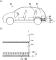
- FIGS. 8 (a) and 8 (b) An example in which the sound absorbing member of the present invention is used as a component for a vehicle and an example of an automobile in which the sound absorbing member of the present invention is disposed will be described with reference to FIGS. 8 (a) and 8 (b).
- Fig.8 (a) is explanatory drawing which shows typically an example of the site
- FIG.8 (b) is a part of the area
- the automobile 91 is provided with a luggage room 93 at the rear of the rear seat 92.
- a plate-like floor member 94 is laid under the luggage room 93, and an underfloor space 95 exists below the floor member 94.
- a steel plate 70 which is a part of the body of the automobile 91 is present, and this steel plate 70 becomes the sound insulation 70 of the soundproof structure 1.
- the sound absorbing member 100 is provided on the sound insulating member 70 so that the open surfaces of the non-through holes face each other, and the soundproof structure 1 including the sound insulating member 70 and the sound absorbing member 100 is disposed in the automobile.
- the thickness of the air layer between the sound insulating member 70 and the sound absorbing member 100 is adjusted so as to enhance the soundproofing characteristics (increase the transmission loss).
- the sound absorbing member in the sound absorbing structure of the present invention can be manufactured, for example, by laminating an upper layer in which a first through hole is provided in a plate material and a lower layer in which a hollow portion is provided.
- the sound absorbing member with one lower layer can be manufactured by the following process. Producing an upper layer which is a plate material having a first through hole; Adjusting the surface roughness of the first through hole; Producing a lower layer which is a plate material having a hollow portion; Step of laminating the upper layer and the lower layer.
- Step of producing upper layer A plate material of a predetermined thickness made of a material such as a resin that can be used as a plate material is prepared.
- the upper layer can be produced by forming the first through hole by means of punching, drilling, laser or the like for the plate material having no through hole.
- a foamed resin composed of expandable resin particles (beads) as a plate material, it is also possible to provide projections for forming the first through holes in the mold to foam the expandable resin particles.
- the upper layer which is a board material which has the 1st penetration hole can be produced.
- Step of adjusting the surface roughness of the first through hole Next, the surface of the first through hole is roughened using sand blast or the like so that the surface roughness Ra of the first through hole is 0.1 to 100 ⁇ m.
- a plate material of a predetermined thickness made of a material such as a resin that can be used as a plate material is prepared.
- a lower layer can be produced by forming a concave portion to be a hollow portion by the middle in the thickness direction of a plate material having no through hole.
- the diameter of the recess is made larger than the diameter of the first through hole.
- the recess is preferably formed by machining, and cutting with an end mill or processing with a hot wire is preferably used.
- the fitting portion male portion or female portion
- Step of laminating upper and lower layers Next, in the case of bonding the upper layer and the lower layer with an adhesive, prepare a sheet-like adhesive in accordance with the shape and position of the recess (hollow part) of the lower layer, and prepare a layer between the upper layer and the lower layer.
- the upper layer and the lower layer can be adhered by the adhesive layer by exerting the adhesive force of the adhesive between them.
- the position of the first through hole of the upper layer and the hollow portion (concave portion) of the lower layer are aligned to form a Helmholtz resonance structure.
- the upper layer and the lower layer are adhered by the adhesive layer by applying the adhesive according to the shape and position of the lower concave portion (hollow part), laminating the upper layer and the lower layer, and exerting the adhesive force of the adhesive. it can.
- the conditions for exerting the adhesive strength of the adhesive conditions in accordance with the adhesive characteristics of the adhesive may be used.
- the upper layer and the lower layer may be stacked while sandwiching a spacer between the upper layer and the lower layer.
- the sound absorbing member with two lower layers can be manufactured by the following process. Producing an upper layer which is a plate material having a first through hole; Adjusting the surface roughness of the first through hole; Producing a side layer which is a plate material having a second through hole; Preparing a plate material to be a bottom layer; By laminating the plate material to be the upper layer, the plate material to be the side layer, and the plate material to be the bottom layer to form a hollow portion by the second through hole and the bottom layer and to form the lower layer consisting of the side layer and the bottom layer Step of laminating the upper layer and the lower layer.
- the upper layer can be manufactured in the same manner as in the case where the lower layer is a single-layer sound absorbing member.
- a plate material of a predetermined thickness made of a material such as a resin that can be used as a plate material is prepared.
- the upper layer can be produced by forming the first through hole by means of punching, drilling, laser or the like for the plate material having no through hole.
- a foamed resin composed of expandable resin particles (beads) as a plate material, it is also possible to provide projections for forming the first through holes in the mold to foam the expandable resin particles.
- the upper layer in which the first through hole is provided in the plate material can be manufactured.
- Step of adjusting the surface roughness of the first through hole Next, the surface of the first through hole is roughened using sand blast or the like so that the surface roughness Ra of the first through hole is 0.1 to 100 ⁇ m.
- a plate material of a predetermined thickness made of a material such as a resin that can be used as a plate material is prepared.
- a side layer can be produced by forming a second through hole by means of punching, drilling, laser or the like for a plate material having no through hole. The diameter of the second through hole is made larger than that of the first through hole.
- a foamed resin composed of expandable resin particles (beads) as a plate material
- projections may be provided in the mold to form the second through holes, and the expandable resin particles may be foamed, too.
- a side layer in which the second through hole is provided in the plate material can be manufactured.
- Step of preparing plate material to be bottom layer A plate made of a material such as resin that can be used as a plate and having a predetermined thickness without a through hole is prepared.
- a fitting part male part or female part
- Step of laminating upper and lower layers When laminating the upper layer and the lower layer (side surface layer and bottom surface layer) with an adhesive, prepare two sheets of sheet-like adhesive cut out according to the shape and position of the second through holes of the side surface layer, The upper layer, the side layer, and the bottom layer can be bonded by the adhesive layer by exerting the adhesive strength of the adhesive between the upper layer and the side layer and between the side layer and the bottom layer. At this time, the Helmholtz resonance structure is formed on the sound absorbing member.
- An adhesive is applied according to the shape and position of the second through hole of the side layer, and the upper layer, the side layer and the bottom layer are laminated to exert the adhesive force of the adhesive, thereby the upper layer, the side layer and the bottom layer Can be adhered by an adhesive layer.
- the conditions for exerting the adhesive strength of the adhesive conditions in accordance with the adhesive characteristics of the adhesive may be used.
- the spacer is interposed between the upper layer and the side layer and between the side layer and the bottom layer.
- the sound absorbing member which is a single layer as a whole, is, for example, a resin layer through the introduction passage and the introduction passage opened on the surface. It can manufacture by forming the non-penetrating hole which has a Helmholtz resonance structure which consists of a hollow part connected with the exterior.
- the method to form a non-penetrating hole in a resin layer is not specifically limited, For example, you may form a through-hole manually by using tools, such as a cutter, in a resin layer.
- the surface of the first through holes is roughened by sand blasting or the like so that the surface roughness Ra of the first through holes is 0.1 to 100 ⁇ m. Good.
- the soundproof structure of the present invention can be obtained by providing the sound insulation material so as to separate the air layer and to separate the air layer by a predetermined distance so as to face the surface of the sound absorption member obtained in this way.
- the sound insulation material may be provided by separately providing a connecting member for providing an air layer between the sound absorption material and the sound insulation material, and the sound absorption material and the sound insulation material may be fixed to the place where the soundproof structure of the present invention is installed.
- the air layer may be provided between the sound insulation member and the sound absorbing member by the above.
- the soundproof member is regarded as a part of the steel plate that constitutes the vehicle body as a sound insulation member, and the sound absorbing member is arranged to be separated from the steel plate by a predetermined distance. A structure may be obtained.
- Example 1 Preparation of Plate Material Primary foam particles (made of polypropylene, average particle diameter: 3.5 mm, foaming agent: carbon dioxide) prepared by prefoaming foamable resin particles are filled in a mold and foam molding is performed by heating steam (143) C. for 10 seconds, removed from the mold, and dried at 80.degree. C. for 12 hours to produce three plate members of 800 mm long x 800 mm wide x 10 mm thick made of a foamed resin. At this time, the expansion ratio of the foamed resin was 30 times.
- foaming agent carbon dioxide
- a through hole (first through hole) having a diameter of 3 mm so as to form a staggered arrangement of the hole pitch of 10 mm in one of the plate members having a thickness of 10 mm manufactured in the above (1) Were drilled to produce the upper layer.
- a circular through hole (second through hole) having a diameter of 10 mm is formed by drilling in another 10 mm thick plate material manufactured in the above (1) so as to form a staggered arrangement of the hole pitch 10 mm.
- the side layer was made.
- One plate having a thickness of 10 mm according to (1) above was not processed but was used as a bottom layer.
- the surface roughness Ra of the first through holes is adjusted to 1.02 ⁇ m by sandblasting (shot blasting apparatus manufactured by Shinto Kogyo Co., Ltd.) The surface of the through hole 1 was roughened.
- Example 2 and 3 and Comparative Examples 1 and 2 Sound absorbing members according to Examples 2 and 3 and Comparative Examples 1 and 2 were obtained in the same manner as Example 1 except that the surface roughness Ra of the first through holes was changed as shown in Table 1. .
- FIG. 9 is an explanatory view schematically showing an outline of a sound transmission loss test on the soundproof structure.
- An acoustic transmission loss measurement device 80 is shown in FIG.
- the sound transmission loss measuring apparatus 80 is provided with a sound source room 81 for generating a sound from the speaker 83 and a sound receiving room 82 for receiving a sound through the soundproof structure 1 as a test body.
- the sound source room side microphone 84 is provided in the sound source room 81, and the sound reception room side microphone 85 is provided in the sound reception room 82, and the sound pressure level L1 measured by the sound source room side microphone 84 and the sound reception room side microphone 85.
- the sound pressure level L2 measured by the above can be taken into the measuring device 86.
- the sound absorbing member and the sound insulating material (that is, the soundproof structure) according to each example and each comparative example are set between the sound source room and the sound receiving room shown in FIG.
- the sound pressure level L1 in the sound source room and the sound pressure level L2 in the sound receiving room were measured, respectively.
- FIGS. 10 (a), 10 (b) and 10 (c) are graphs showing the relationship between the frequency and the transmission loss in Examples 1, 2 and 3, respectively.
- FIGS. 11A and 11B are graphs showing the relationship between the frequency and the transmission loss in Comparative Examples 1 and 2, respectively. In each graph, plots of frequencies of 1000 Hz and 1600 Hz are shown in white, and these values are also shown in Table 1.
Landscapes
- Physics & Mathematics (AREA)
- Acoustics & Sound (AREA)
- Engineering & Computer Science (AREA)
- Multimedia (AREA)
- Mechanical Engineering (AREA)
- Vehicle Interior And Exterior Ornaments, Soundproofing, And Insulation (AREA)
- Body Structure For Vehicles (AREA)
- Soundproofing, Sound Blocking, And Sound Damping (AREA)
Abstract
L'invention concerne une structure insonore qui est constituée d'un élément absorbant acoustique doté de trous non-débouchant, et d'un matériau d'isolation phonique qui est agencé en vis-à-vis avec une face d'ouverture desdits trous non-débouchant dudit élément absorbant acoustique, et séparé selon une distance prédéfinie d'une couche d'air. La structure insonore de l'invention est caractéristique en ce que lesdits trous non-débouchantdudit élément absorbant acoustique possèdent une structure de résonance de Helmholtz qui est constituée d'une partie vide connectée à un trajet d'introduction ouvert en surface et à une partie externe via ledit trajet d'introduction. En outre, la rugosité superficielle (Ra) dudit trajet d'introduction est comprise entre 0,1 et 100μm.
Priority Applications (2)
| Application Number | Priority Date | Filing Date | Title |
|---|---|---|---|
| JP2019532340A JPWO2019021478A1 (ja) | 2017-07-28 | 2017-07-28 | 防音構造体、車両用部品及び自動車 |
| PCT/JP2017/027531 WO2019021478A1 (fr) | 2017-07-28 | 2017-07-28 | Structure insonore, composant pour véhicule, et automobile |
Applications Claiming Priority (1)
| Application Number | Priority Date | Filing Date | Title |
|---|---|---|---|
| PCT/JP2017/027531 WO2019021478A1 (fr) | 2017-07-28 | 2017-07-28 | Structure insonore, composant pour véhicule, et automobile |
Publications (1)
| Publication Number | Publication Date |
|---|---|
| WO2019021478A1 true WO2019021478A1 (fr) | 2019-01-31 |
Family
ID=65040128
Family Applications (1)
| Application Number | Title | Priority Date | Filing Date |
|---|---|---|---|
| PCT/JP2017/027531 Ceased WO2019021478A1 (fr) | 2017-07-28 | 2017-07-28 | Structure insonore, composant pour véhicule, et automobile |
Country Status (2)
| Country | Link |
|---|---|
| JP (1) | JPWO2019021478A1 (fr) |
| WO (1) | WO2019021478A1 (fr) |
Cited By (2)
| Publication number | Priority date | Publication date | Assignee | Title |
|---|---|---|---|---|
| CN111688599A (zh) * | 2019-03-14 | 2020-09-22 | 本田技研工业株式会社 | 隔音结构 |
| WO2020192160A1 (fr) * | 2019-03-28 | 2020-10-01 | 苏州拓朴声学科技有限公司 | Module intégré d'absorption des sons et d'isolation vis-à-vis des sons normalisé et procédé de sélection |
Citations (2)
| Publication number | Priority date | Publication date | Assignee | Title |
|---|---|---|---|---|
| JP2012013912A (ja) * | 2010-06-30 | 2012-01-19 | Three M Innovative Properties Co | 吸音システム及びその作製方法 |
| JP2015151105A (ja) * | 2014-02-19 | 2015-08-24 | 河西工業株式会社 | 車体パネル構造体 |
Family Cites Families (7)
| Publication number | Priority date | Publication date | Assignee | Title |
|---|---|---|---|---|
| JPS515424A (en) * | 1974-07-04 | 1976-01-17 | Nissan Diesel Motor Co | Enjinruumuno kyuonsochi |
| JP2000034937A (ja) * | 1998-07-17 | 2000-02-02 | Mitsubishi Motors Corp | 吸音装置 |
| JP2006199276A (ja) * | 2004-12-24 | 2006-08-03 | Kobe Steel Ltd | 吸音構造 |
| JP5359167B2 (ja) * | 2008-10-07 | 2013-12-04 | ヤマハ株式会社 | 車体構造体および荷室 |
| JP2011111103A (ja) * | 2009-11-30 | 2011-06-09 | Iseki & Co Ltd | 防振キャビン型作業車両 |
| JP5541742B2 (ja) * | 2011-06-10 | 2014-07-09 | アイシン化工株式会社 | 熱硬化防音塗料組成物 |
| JP6588324B2 (ja) * | 2015-12-11 | 2019-10-09 | 小島プレス工業株式会社 | 車両用樹脂製外装品 |
-
2017
- 2017-07-28 WO PCT/JP2017/027531 patent/WO2019021478A1/fr not_active Ceased
- 2017-07-28 JP JP2019532340A patent/JPWO2019021478A1/ja active Pending
Patent Citations (2)
| Publication number | Priority date | Publication date | Assignee | Title |
|---|---|---|---|---|
| JP2012013912A (ja) * | 2010-06-30 | 2012-01-19 | Three M Innovative Properties Co | 吸音システム及びその作製方法 |
| JP2015151105A (ja) * | 2014-02-19 | 2015-08-24 | 河西工業株式会社 | 車体パネル構造体 |
Cited By (2)
| Publication number | Priority date | Publication date | Assignee | Title |
|---|---|---|---|---|
| CN111688599A (zh) * | 2019-03-14 | 2020-09-22 | 本田技研工业株式会社 | 隔音结构 |
| WO2020192160A1 (fr) * | 2019-03-28 | 2020-10-01 | 苏州拓朴声学科技有限公司 | Module intégré d'absorption des sons et d'isolation vis-à-vis des sons normalisé et procédé de sélection |
Also Published As
| Publication number | Publication date |
|---|---|
| JPWO2019021478A1 (ja) | 2020-05-28 |
Similar Documents
| Publication | Publication Date | Title |
|---|---|---|
| JP7012085B2 (ja) | 吸音部材、車両用部品及び自動車 | |
| CN100575149C (zh) | 隔音系统 | |
| US11881198B2 (en) | Noise insulation material for automobile | |
| JP7783186B2 (ja) | メタマテリアル遮音デバイス | |
| WO2019026294A1 (fr) | Élément d'absorption sonore, composant de véhicule et automobile | |
| KR101874305B1 (ko) | 차량용 플로워카페트 및 그의 제조방법 | |
| CN109952608A (zh) | 声学泡沫去耦器 | |
| JP2020007975A (ja) | コンプレッサー用防音材 | |
| US20190147843A1 (en) | Method for the manufacture of vibration damping and/or sound attenuating materials | |
| WO2019008774A1 (fr) | Matériau absorbant le son, composant pour véhicule, et automobile | |
| WO2019021478A1 (fr) | Structure insonore, composant pour véhicule, et automobile | |
| Jonza et al. | Acoustically absorbing lightweight thermoplastic honeycomb panels | |
| JP4079851B2 (ja) | 防音材 | |
| WO2019021480A1 (fr) | Élément absorbant acoustique ainsi que procédé de fabrication de celui-ci, composant pour véhicule, et automobile | |
| JP6916879B2 (ja) | 防音構造体、車両用部品及び自動車 | |
| WO2018189879A1 (fr) | Véhicule ferroviaire | |
| WO2019021477A1 (fr) | Élément absorbant acoustique, composant pour véhicule, et automobile | |
| JP2018158691A (ja) | 車両用吸音材、車両用部品、自動車及び自動車用仕切り部材 | |
| JP2020008684A (ja) | 防音構造体 | |
| CN213199014U (zh) | 汽车门板隔音隔热吸能减震垫 | |
| JP2023154823A (ja) | 吸音材の製造方法、吸音材、及び車両部材 | |
| JP2022162917A (ja) | 積層パネル |
Legal Events
| Date | Code | Title | Description |
|---|---|---|---|
| 121 | Ep: the epo has been informed by wipo that ep was designated in this application |
Ref document number: 17918996 Country of ref document: EP Kind code of ref document: A1 |
|
| ENP | Entry into the national phase |
Ref document number: 2019532340 Country of ref document: JP Kind code of ref document: A |
|
| NENP | Non-entry into the national phase |
Ref country code: DE |
|
| 122 | Ep: pct application non-entry in european phase |
Ref document number: 17918996 Country of ref document: EP Kind code of ref document: A1 |