WO2019021480A1 - Élément absorbant acoustique ainsi que procédé de fabrication de celui-ci, composant pour véhicule, et automobile - Google Patents
Élément absorbant acoustique ainsi que procédé de fabrication de celui-ci, composant pour véhicule, et automobile Download PDFInfo
- Publication number
- WO2019021480A1 WO2019021480A1 PCT/JP2017/027545 JP2017027545W WO2019021480A1 WO 2019021480 A1 WO2019021480 A1 WO 2019021480A1 JP 2017027545 W JP2017027545 W JP 2017027545W WO 2019021480 A1 WO2019021480 A1 WO 2019021480A1
- Authority
- WO
- WIPO (PCT)
- Prior art keywords
- layer
- plate material
- absorbing member
- hole
- sound absorbing
- Prior art date
- Legal status (The legal status is an assumption and is not a legal conclusion. Google has not performed a legal analysis and makes no representation as to the accuracy of the status listed.)
- Ceased
Links
Images


Classifications
-
- B—PERFORMING OPERATIONS; TRANSPORTING
- B60—VEHICLES IN GENERAL
- B60R—VEHICLES, VEHICLE FITTINGS, OR VEHICLE PARTS, NOT OTHERWISE PROVIDED FOR
- B60R13/00—Elements for body-finishing, identifying, or decorating; Arrangements or adaptations for advertising purposes
- B60R13/08—Insulating elements, e.g. for sound insulation
-
- G—PHYSICS
- G10—MUSICAL INSTRUMENTS; ACOUSTICS
- G10K—SOUND-PRODUCING DEVICES; METHODS OR DEVICES FOR PROTECTING AGAINST, OR FOR DAMPING, NOISE OR OTHER ACOUSTIC WAVES IN GENERAL; ACOUSTICS NOT OTHERWISE PROVIDED FOR
- G10K11/00—Methods or devices for transmitting, conducting or directing sound in general; Methods or devices for protecting against, or for damping, noise or other acoustic waves in general
- G10K11/16—Methods or devices for protecting against, or for damping, noise or other acoustic waves in general
- G10K11/162—Selection of materials
- G10K11/168—Plural layers of different materials, e.g. sandwiches
-
- G—PHYSICS
- G10—MUSICAL INSTRUMENTS; ACOUSTICS
- G10K—SOUND-PRODUCING DEVICES; METHODS OR DEVICES FOR PROTECTING AGAINST, OR FOR DAMPING, NOISE OR OTHER ACOUSTIC WAVES IN GENERAL; ACOUSTICS NOT OTHERWISE PROVIDED FOR
- G10K11/00—Methods or devices for transmitting, conducting or directing sound in general; Methods or devices for protecting against, or for damping, noise or other acoustic waves in general
- G10K11/16—Methods or devices for protecting against, or for damping, noise or other acoustic waves in general
- G10K11/172—Methods or devices for protecting against, or for damping, noise or other acoustic waves in general using resonance effects
Definitions
- the present invention relates to a sound absorbing member, a component for a vehicle, a car, and a method of manufacturing the sound absorbing member.
- a vehicle such as a car is a machine that has a power source such as an engine and can be moved by human operation, and generates various vibrations and noises.
- the sounds transmitted to the inside of the vehicle include not only the sounds emitted by the power source but also the sounds generated outside the vehicle such as road noise, tire pattern noise and wind noise generated when the vehicle travels. .
- these sounds When these sounds are transmitted to the inside of the vehicle, they cause discomfort to people, so sound insulation and sound absorbing members are used in the engine, engine room, interior, body, exhaust pipe, etc. Measures have been taken.
- the noise generated from the road surface during traveling such as tire pattern noise (in a frequency range of 500 to 3000 Hz and simply referred to as pattern noise) is less likely to be reflected and diffused around the lower part of the vehicle body, and the degree of sound intruding into the vehicle Is estimated to be high. Similar problems can occur with electric vehicles.
- noise that was conventionally diffused outside the vehicle is transmitted to a person riding the vehicle.
- these noises are likely to intrude from the bottom of the rear portion of the vehicle and the lower portion of the luggage room (under floor space) where the accommodation space is disposed. Since these noises include noise in the frequency range of 500 to 2000 Hz that people feel uncomfortable, it is required to take measures.
- Patent Document 1 a surface layer having micropores formed on the surface, a communication passage communicating with the micropores, and an inner portion deeper than the surface layer are formed, and are larger than the volumes of the micropores and the communication passage.
- the sound absorption characteristic structure which comprises an acoustic void of a porous layer having a volume and in which a part of the acoustic void is in communication with the fine pore through the communication passage is disclosed.
- Patent Document 1 With reference to paragraph [0032] of Patent Document 1, the sound absorption characteristic structure disclosed in Patent Document 1 is obtained by heating and foaming a composition containing a synthetic resin as a main component and a foaming agent. It is supposed to be Further, in the same paragraph, the foamed structure of urethane resin having the surface state shown in FIG. 2 and the cross section shown in FIG. 3 is considered.
- Patent Document 1 describes that the micropores and the acoustic pores are formed by the decomposition gas of the foaming agent, and the passage of the decomposition gas from the acoustic pores to the micropores becomes a communication path. ing.
- the material of the sound absorption member is manufactured by the method of forming the fine holes, the acoustic holes, and the communication passage by the decomposition gas of the foaming agent.
- these materials were machined with a drill or the like in order to provide an opening having a Helmholtz resonance structure, the sound absorbing member was cracked. The cause of the crack was judged to be a communicating hole formed by the foaming agent. Therefore, it has become necessary to manufacture a sound absorbing member having a Helmholtz resonance structure from a plate having no communicating hole formed by foaming.
- the present invention is an invention made in view of the above-mentioned problems, and an object of the present invention is to provide a sound absorbing member which prevents the generation of secondary radiation sound and reliably achieves a predetermined sound absorbing characteristic.
- the inventors of the present invention form a through hole serving as an introduction passage to a plate material having no communication hole formed by foaming to form an upper layer, prepare a lower layer separately provided with a hollow portion, and use an adhesive layer.
- a sound absorbing member having a Helmholtz resonance structure consisting of an introduction passage and a hollow portion. Then, the inventors have found that such a sound absorbing member can surely achieve a predetermined sound absorbing characteristic, and completed the present invention.
- the sound absorbing member of the present invention is a sound absorbing member having a Helmholtz resonance structure including an introduction passage opened on the surface and a hollow portion connected to the outside through the introduction passage, It is made of plate material without continuous holes formed by foaming, An upper layer provided with a columnar first through hole forming the introduction passage; A lower layer provided with the hollow portion laminated on the upper layer; An adhesive layer for bonding the upper layer and the lower layer,
- the portion of the sound absorbing member where the Helmholtz resonance structure is not formed is characterized in that the compressive stress ⁇ measured in the thickness direction according to JIS K 7181 (2011) is 0.1 to 200 MPa.
- the upper layer is provided in advance with a columnar first through hole, which is a through hole provided at a predetermined position in a predetermined shape with respect to the plate material, and therefore the position and the shape thereof are as designed before lamination. It is controlled.
- the hollow portion is provided in advance in the lower layer, which is also a hollow portion provided at a predetermined position with a predetermined shape, the position and the shape are controlled as designed before lamination.
- the plate material vibrates during sound absorption and a secondary radiation sound is generated, but the adhesive action is achieved by bonding the upper layer and the lower layer And the influence of secondary radiation can be reduced.
- the compressive stress of the sound absorbing member is 0.1 MPa or more, the vibration is prevented from propagating in the horizontal direction and the generation of radiated sound is prevented, and when the compressive stress is 200 MPa or less, the vibration propagates in the thickness direction Generation of secondary radiation noise is prevented.
- the first through hole is preferably a through hole formed by machining.
- the plate material constituting the upper layer is made of resin.
- the said resin is a foamed resin. If the plate material constituting the upper layer is made of resin, weight reduction can be easily achieved, which is particularly desirable as a component for a vehicle. In addition, when the resin is a foamed resin, the weight thereof can be made lighter, which can contribute to the improvement of the fuel efficiency when it is used as a component for a vehicle.
- the plate material constituting the upper layer may be a composite material of resin and fiber. As a method of complexing, resin and fiber may be mixed, or resin and fiber may be combined in block form.
- the lower layer is a side surface layer in which a pillar-shaped second through hole having a larger opening diameter than the first through hole is provided on a plate member having no communication hole formed by foaming.
- a bottom surface layer formed of a plate material and not provided with the through holes be sequentially stacked, and the hollow portion be formed of the second through holes and the bottom surface layer.
- the second through hole is preferably a through hole formed by machining.
- the plate material constituting the side layer and the bottom layer be made of resin.
- the said resin is a foamed resin. It is particularly desirable as a component for a vehicle because weight reduction can be easily achieved when the plate material forming the side layer and the bottom layer is made of resin.
- the resin when the resin is a foamed resin, the weight thereof can be made lighter, which can contribute to the improvement of the fuel efficiency when it is used as a component for a vehicle.
- the plate material constituting the side layer and the bottom layer may be a composite material of resin and fiber. As a method of complexing, resin and fiber may be mixed, or resin and fiber may be combined in block form.
- a fiber layer is further formed on the surface on the opening formation side of the plate material constituting the upper layer, It is preferable that an opening communicating with the opening of the introduction passage is formed in the fiber layer.
- the sound absorbing member has a Helmholtz resonance structure, it can absorb sound in a predetermined frequency range, but the width of the frequency range that can absorb sound is not wide, and in particular, it is difficult to sufficiently absorb sound in a high frequency range of 2000 Hz or more. .
- the fiber layer is formed, sound in a high frequency region of 2000 Hz or more can be absorbed.
- the parts for vehicles of the present invention are characterized by including the sound absorbing member of the present invention.
- the sound absorbing member of the present invention is excellent as a part for vehicles because it is excellent in soundproofing performance.
- a raising member, a partition member, a luggage box, etc. are mentioned.
- An automobile according to the present invention is characterized in that the introduction passage of the sound absorbing member according to the present invention is disposed in the direction of the road surface.
- One aspect of a method of manufacturing a sound absorbing member according to the present invention is a method of manufacturing a sound absorbing member having a Helmholtz resonance structure including an introduction passage opened on the surface and a hollow portion connected to the outside through the introduction passage. , Producing an upper layer which is a plate material having a columnar first through hole serving as an introduction passage; Producing a lower layer which is a plate material having a hollow portion; Bonding the upper layer and the lower layer with an adhesive layer; The plate material constituting the upper layer is characterized in that the plate material does not have a communication hole formed by foaming.
- the strength of the plate material is sufficient, which is suitable for forming the first through hole.
- the influence of the secondary radiation sound can be reduced by bonding such upper and lower layers, the generation of the secondary radiation sound can be prevented, and a predetermined sound absorption characteristic can be surely achieved.
- a sound absorbing member can be provided.
- the upper layer by forming a first through hole by machining the plate material having no through hole. Since a plate material having no communication holes formed by foaming is used as a material of the upper layer, the strength of the plate material is sufficient, and breakage can be prevented from occurring when forming the first through holes by machining.
- a lower layer is produced by machining a hollow portion to be a hollow portion halfway through the thickness direction of a plate material having no through hole. It is preferable to do. It is preferable to form a recess to be a hollow portion by machining because it is easy to control the position and shape of the hollow portion.
- Another aspect of the method of manufacturing a sound absorbing member according to the present invention is a method of manufacturing a sound absorbing member having a Helmholtz resonance structure including an introduction passage opened on the surface and a hollow portion connected to the outside via the introduction passage. , Producing an upper layer which is a plate material having a columnar first through hole serving as an introduction passage; Producing a side layer which is a plate material having a second through hole; Preparing a plate material to be a bottom layer; A plate serving as the upper layer, a plate serving as the side layer, and a plate serving as the bottom layer are stacked to form a hollow portion by the second through hole and the bottom layer, and a lower layer comprising the side layer and the bottom layer is formed. Bonding the lower layer with an adhesive layer, The plate material forming the upper layer and the plate material forming the side surface layer are characterized in that they are plate materials having no communication holes formed by foaming.
- the strength of the plate material is sufficient, which is suitable for forming the first through hole.
- a plate material having no communication holes formed by foaming as a plate material forming the side layer the strength of the plate material is sufficient, which is suitable for forming the second through hole.
- the hollow portion can be easily formed by laminating the lower layer as two layers of the side surface layer and the bottom surface layer.
- an upper layer by forming a 1st through-hole by machining with respect to the board
- plate material which does not have a through-hole by the other aspect of the manufacturing method of the sound-absorbing member of this invention. Since a plate material having no communication holes formed by foaming is used as a material of the upper layer, the strength of the plate material is sufficient, and breakage can be prevented from occurring when forming the first through holes by machining.
- a side layer by forming a 2nd through-hole by machining with respect to the board
- FIG. 1 is a cross-sectional view schematically showing an example of the sound absorbing member of the present invention.
- FIG. 2 is a cross-sectional view schematically showing another example of the sound absorbing member of the present invention.
- Fig.3 (a) is explanatory drawing which shows typically an example of the site
- FIG.3 (b) is partial expansion of the area
- FIG. FIG. 4 is a perspective view schematically showing an example of the method of manufacturing a sound absorbing member of the present invention.
- FIG. 5 is a perspective view schematically showing another example of the method of manufacturing a sound absorbing member of the present invention.
- FIG. 4 is explanatory drawing which shows typically an example of the site
- FIG.3 (b) is partial expansion of the area
- 6 is an explanatory view schematically showing an outline of a confirmation test of the secondary radiation sound.
- 7 (a), 7 (b), 7 (c), 7 (d), 7 (e) and 7 (f) respectively correspond to Example 1 and Comparative Examples 1 to 5.
- 5 is a graph showing the relationship between frequency and transmission loss.
- the sound absorbing member of the present invention is a sound absorbing member having a Helmholtz resonance structure including an introduction passage opened on the surface and a hollow portion connected to the outside through the introduction passage, It consists of plate material which does not have a communicating hole formed by foaming, An upper layer provided with a columnar first through hole forming the introduction passage; A lower layer provided with the hollow portion laminated on the upper layer; An adhesive layer for bonding the upper layer and the lower layer,
- the portion of the sound absorbing member where the Helmholtz resonance structure is not formed is characterized in that the compressive stress ⁇ measured in the thickness direction according to JIS K 7181 (2011) is 0.1 to 200 MPa. In addition, when compressive stress (sigma) is measured at 23 degreeC, let distortion amount be the maximum value in 10 to 50%.
- the sound absorbing member of the present invention has a Helmholtz resonance structure including an introduction passage opened on the surface and a hollow portion connected to the outside through the introduction passage.
- the sound absorbing member of the present invention is constituted by the laminated structure of the upper layer and the lower layer, the first through hole serving as the introduction passage is present in the upper layer, and the hollow portion is present in the lower layer.
- a Helmholtz resonance structure is formed.
- the configuration of the sound absorbing member of the present invention will be described separately for the upper layer and the lower layer.
- the upper layer is made of a plate material, and the plate material is provided with a first through hole.
- the plate material constituting the upper layer is made of a plate material having no communication hole formed by foaming.
- the first through hole is in a columnar shape, and is a portion having a columnar space only with air. It is preferable that the diameter of the through hole is constant from the inlet side to the outlet side in the thickness direction of the plate material. That is, it does not include a form in which gas passes in the thickness direction but the other side is not visible (does not penetrate) in top view in the thickness direction, such as communicating pores in a porous material.
- the first through hole is preferably a through hole formed by machining a plate having no through hole, and punching, drilling or laser drilling is preferably used.
- the first through hole is desirably cylindrical, and the cross-sectional shape in the direction perpendicular to the longitudinal direction is preferably a perfect circle.
- the introduction passage has a cylindrical shape. It is advantageous that the introduction passage has a cylindrical shape because the sound absorption characteristics do not have anisotropy.
- the diameter of the bottom surface in the case where the first through hole is cylindrical is preferably 1 to 30 mm. That is, in the sound absorbing member of the present invention, the inner diameter of the introduction passage is preferably 1 to 30 mm.
- the diameter of the first through hole is determined as a circle equivalent diameter.
- the equivalent circle diameter is the diameter when the cross-sectional area of the first through hole when cutting the first through hole in the direction perpendicular to the length direction is replaced with a true circle of the same area.
- the diameter may be used as the equivalent circle diameter.
- the arrangement pattern of the first through holes provided in the upper layer is a square arrangement in which the first through holes are arranged at the apexes of the squares in a plane in which the squares are continuously arranged vertically and horizontally. It may be a staggered arrangement in which first through holes are arranged at the apexes of triangles in a plane in which regular triangles are arranged continuously in the vertical and horizontal directions. Among these, a staggered arrangement is desirable. When the arrangement pattern of the first through holes is a staggered arrangement, the adjacent first through holes are likely to be equally spaced, so that the sound absorbing effect is improved. Moreover, the strength as a plate material of the upper layer is obtained.
- the plate material constituting the upper layer is preferably made of resin.
- the resin is preferably an elastomer such as a foamed resin or rubber. If the plate material constituting the upper layer is made of resin, weight reduction can be easily achieved, which is particularly desirable as a component for a vehicle. In addition, when the resin is a foamed resin, the weight thereof can be made lighter, which can contribute to the improvement of the fuel efficiency when it is used as a component for a vehicle.
- the resin which is a material of the plate material constituting the upper layer is not formed with a hole serving as a communicating hole in the resin.
- the plate material constituting the upper layer may be a composite material of resin and fiber. As a method of complexing, resin and fiber may be mixed, or resin and fiber may be combined in block form.
- the resin be any of a foamed resin composed of expandable resin particles (beads), a foamed resin having cells, a thermoplastic resin, and a thermosetting resin. It is preferable that the material of the resin has a density of 0.01 to 1 g / cm 3 , and more preferably, the density of the resin is 0.02 to 0.1 g / cm 3 .
- the density of the resin indicates the density of the foamed resin that has been foam-molded. If the density of the resin is within the above range, it is easy to obtain the strength necessary for the sound absorbing member.
- the resin is more preferably a foamed resin comprising expandable resin particles (beads).
- the resin is a foamed resin composed of expandable resin particles (beads)
- the weight of the sound absorbing member can be reduced while maintaining the strength, which can contribute to the improvement of fuel efficiency when used for parts for vehicles .
- the foamed resin is obtained by foaming and molding expandable resin particles.
- a plate material which is a foamed resin comprising expandable resin particles (beads) does not have a communication hole.
- the expandable resin particles (beads) used as the plate material constituting the upper layer are particles containing a foaming agent inside the resin particles, and known materials can be suitably used.
- the resin component constituting the expandable resin particles include olefin resins such as polyethylene and polypropylene, and styrene resins such as polystyrene.
- a styrene resin a copolymer obtained by copolymerizing a styrene homopolymer, styrene, and a monomer (or its derivative) copolymerizable with styrene is mentioned.
- the styrene copolymer may be any of a block copolymer, a random copolymer, and a graft copolymer.
- the blowing agent include hydrocarbons such as propane, butane and pentane.
- the expandable resin particles used as the plate material constituting the upper layer may be, if necessary, a flame retardant, a flame retardant aid, a processing aid, a filler, an antioxidant, light stability.
- Known additives such as an agent, an antistatic agent and a colorant may be added.
- an additive if a black thing is used for a coloring agent, a stain will become inconspicuous.
- Flame retardants include hydrated metal flame retardants such as aluminum hydroxide and magnesium hydroxide, phosphoric acid flame retardants such as red phosphorus and ammonium phosphate, tetrabromobisphenol A (TABB), brominated polystyrene, chlorinated paraffin And halogen-based flame retardants, ammonium carbonate, nitrogen-based flame retardants such as melamine cyanurate, and the like.
- phosphoric acid flame retardants such as red phosphorus and ammonium phosphate, tetrabromobisphenol A (TABB), brominated polystyrene, chlorinated paraffin And halogen-based flame retardants, ammonium carbonate, nitrogen-based flame retardants such as melamine cyanurate, and the like.
- TABB tetrabromobisphenol A
- brominated polystyrene chlorinated paraffin And halogen-based flame retardants
- ammonium carbonate such as melamine cyanurate
- antioxidant examples include alkylphenols, alkylene bisphenols, alkylphenol thioethers, ⁇ , ⁇ -thiopropionic acid esters, organic phosphites and phenol-nickel complexes.
- light fastness stabilizer examples include benzotriazole-based UV absorbers and hindered amine-based stabilizers.
- antistatic agent examples include low molecular weight antistatic agents such as fatty acid ester compounds, aliphatic ethanolamine compounds and aliphatic ethanolamide compounds, and high molecular weight antistatic agents.
- a coloring agent a dye, a pigment, etc. are mentioned.
- the average particle diameter of the expandable resin particles used as a plate material constituting the upper layer is preferably 300 ⁇ m to 2400 ⁇ m, and more preferably 800 ⁇ m to 2000 ⁇ m.
- the expansion ratio of the expandable resin particles is desirably 10 to 60 times. By setting the expansion ratio to 10 to 60 times, the density of the resin can be easily adjusted to the range of 0.02 to 0.1 g / cm 3 . On the other hand, if the expansion ratio is less than 10 times, the sound absorbing member may be too hard or too heavy. When the expansion ratio exceeds 60 times, the strength of the sound absorbing member may be insufficient.
- polyurethane or the like can be used as the foamed resin used as the plate material constituting the upper layer.
- a foaming agent and the like By mixing polyurethane as a main ingredient, a foaming agent and the like, and foaming and forming the mixture, a foamed resin having cells can be obtained, whereby a plate material can be manufactured.
- the resin used as the plate material constituting the upper layer may be a thermoplastic resin or a thermosetting resin.
- a thermoplastic resin used as a plate material constituting the upper layer polypropylene resin, polyethylene resin, polyester resin (such as nylon 6-6), polystyrene resin or the like can be used.
- a sound absorbing member can be manufactured by molding a thermoplastic resin as a resin pellet, heating the resin pellet, and performing a molding process such as injection molding and extrusion molding.
- thermosetting resin used as the plate material constituting the upper layer.
- the sound absorbing member can be manufactured by preheating the thermosetting resin, placing it in a mold, pressurizing it, raising the temperature of the mold and curing it.
- the plate material constituting the upper layer materials such as inorganic materials and metal materials may be used in addition to the resin.
- the plate material constituting the upper layer preferably has a compressive stress of 0.1 to 200 MPa as its material.
- foamed polypropylene can be preferably used as the foamed resin, it is more preferable to prepare and use the foamed polypropylene having a compressive stress of about 0.2 to 1.0 MPa by adjusting the foaming ratio and the like.
- expanded polystyrene can be preferably used as the expanded resin, it is more preferable to prepare expanded polystyrene having a compressive stress of about 0.1 to 1.0 MPa by adjusting the expansion ratio and the like.
- nylon 6-6 can be preferably used, but it is more preferable to prepare nylon 6-6 having a compressive stress of 80 to 100 MPa by adjusting its molecular weight, crosslinking density and the like.
- polyethylene resin can be preferably used, but it is more preferable to prepare and use a polyethylene resin having a compressive stress of 22 to 30 MPa by adjusting its molecular weight, crosslink density and the like.
- a polypropylene resin can be preferably used, but it is more preferable to prepare and use a polypropylene resin having a compressive stress of 40 to 50 MPa by adjusting its molecular weight, crosslinking density and the like.
- a phenol resin can be preferably used, but it is more preferable to prepare and use a phenol resin having a compressive stress of 140 to 200 MPa by adjusting its molecular weight, crosslinking density and the like.
- an epoxy resin can be preferably used, but it is more preferable to prepare and use an epoxy resin having a compressive stress of about 110 to 200 MPa by adjusting its molecular weight, crosslinking density and the like.
- the compressive stress of the plate material can be measured in the thickness direction according to JIS K 7181 (2011).
- the thickness of the plate constituting the upper layer is preferably 1 to 20 mm.
- the thickness of the plate is the length of the first through hole and the length of the introduction passage. That is, the length of the first through hole is preferably 1 to 20 mm. Further, the length of the introduction passage is also preferably 1 to 20 mm.
- a fiber layer is further formed on the surface on the opening formation side of the plate material constituting the upper layer, and the fiber layer is formed with an opening communicating with the opening of the introduction passage.
- the sound absorbing member has a Helmholtz resonance structure, it can absorb sound in a predetermined frequency range, but the width of the frequency range that can absorb sound is not wide, and in particular, it is difficult to sufficiently absorb sound in a high frequency range of 2000 Hz or more. .
- the fiber layer is formed, sound in a high frequency region of 2000 Hz or more can be absorbed.
- the material constituting the fiber layer is preferably selected from natural fibers, synthetic resin fibers, and inorganic fibers.
- Natural fibers include vegetable fibers, animal fibers and mineral fibers.
- synthetic resin fibers include polyamide resins (nylon etc.), polyester resins (polyethylene terephthalate (PET), polyethylene naphthalate (PEN) etc.), acrylic resins, polyvinyl alcohol resins, polyolefin resins (polyethylene, polypropylene etc.) etc. It can be mentioned.
- As the inorganic fibers alumina fibers, silica fibers, silica-alumina fibers, glass fibers, carbon fibers, potassium titanate fibers, rock wool and the like can be mentioned.
- the fiber layer may be formed as a felt or non-woven fabric.
- the thickness of the fiber layer is preferably 1 to 20 mm.
- air vibration occurs in the space, and sound in a high frequency region can be absorbed.
- the upper layer and the fiber layer may or may not be bonded by an adhesive layer.
- a hollow portion is provided and laminated with the upper layer.
- the lower hollow portion is connected to the first through hole of the upper layer, that is, the introduction passage, whereby the hollow portion is connected to the outside to form a Helmholtz resonance structure.
- the upper layer and the lower layer are bonded by an adhesive layer.
- the hollow portion provided in the lower layer preferably has a cylindrical shape, and the cross-sectional shape in the direction perpendicular to the longitudinal direction preferably is a perfect circle.
- the height is preferably 1 to 20 mm, and more preferably 3 to 15 mm.
- the diameter of the hollow portion is determined as the equivalent circle diameter.
- the equivalent circle diameter is the diameter when the cross-sectional area of the hollow portion when the hollow portion is cut in the direction perpendicular to the length direction is replaced with a true circle of the same area.
- the diameter of the hollow portion is preferably 4 to 171 mm, preferably 10 mm or more, and more preferably 150 mm or less.
- the arrangement pattern of the hollow portions provided in the lower layer may be a tetragonal arrangement in which the hollow portions are disposed at the apexes of squares in a plane in which squares are continuously arranged vertically and horizontally. It may be a staggered arrangement in which hollows are arranged at the apexes of triangles in a plane arranged continuously to. Among these, a staggered arrangement is desirable. If the arrangement pattern of the hollow portions is a staggered arrangement, the adjacent hollow portions are likely to be equally spaced, so that the sound absorption effect is improved. In addition, the strength as a lower plate material can be obtained.
- the positional relationship between the introduction passage and the hollow portion may be such that the hollow portion is connected to the outside through the introduction passage, and the center of the introduction passage and the hollow portion (in the direction perpendicular to the thickness direction The center in the cross-sectional shape at the time of cutting may or may not coincide.
- a Helmholtz resonance structure is formed so that one hollow portion corresponds to one introduction passage.
- the specific configuration of the lower layer will be described separately in the case of one layer and in the case of two layers.
- the lower layer is a single layer, there is a form in which a concave portion is formed midway in the thickness direction of one plate material constituting the lower layer to form a hollow portion.
- the layers constituting the sound absorbing member of the present invention are two layers, the upper layer and the lower layer, excluding the adhesive layer.
- the lower layer is two layers
- the layers constituting the sound absorbing member of the present invention are three layers of the upper layer, the side layer and the bottom layer, except for the adhesive layer.
- a recess is formed in the middle of the thickness direction of one plate member constituting the lower layer to form a hollow portion.
- the concave portion is a portion which is a columnar space having an open upper surface, surrounded by the bottom surface and the side surface, with the material constituting the plate material as the bottom surface and the side surface.
- the diameter of the recess is preferably constant from the top surface to the bottom surface. Moreover, it is preferable that the diameter of the bottom face of the recess is larger than the diameter of the first through hole that constitutes the upper layer.
- the diameter of the bottom of the recess is preferably 4 to 171 mm, preferably 10 mm or more, and more preferably 150 mm or less.
- the height of the recess is preferably 1 to 20 mm, and more preferably 3 to 15 mm.
- the recess (hollow portion) is preferably formed by machining a plate having no through hole, and cutting with an end mill or processing with a hot wire is suitably used.
- a foamed resin comprising expandable resin particles (beads) as a plate material
- the plate constituting the lower layer is made of resin.
- the resin is preferably an elastomer such as a foamed resin or rubber.
- plate material which comprises a lower layer consists of a board
- the resin is a foamed resin, the weight thereof can be made lighter, which can contribute to the improvement of the fuel efficiency when it is used as a component for a vehicle.
- the plate material constituting the lower layer may be a composite material of resin and fiber.
- resin and fiber may be mixed, or resin and fiber may be combined in block form.
- the resin be any of a foamed resin composed of expandable resin particles (beads), a foamed resin having cells, a thermoplastic resin, and a thermosetting resin. It is preferable that the material of the resin has a density of 0.01 to 1 g / cm 3 , and more preferably, the density of the resin is 0.02 to 0.1 g / cm 3 .
- the density of the resin indicates the density of the foamed resin that has been foam-molded. If the density of the resin is within the above range, it is easy to obtain the strength necessary for the sound absorbing member.
- the resin is more preferably a foamed resin comprising expandable resin particles (beads).
- the resin is a foamed resin composed of expandable resin particles (beads)
- the weight of the sound absorbing member can be reduced while maintaining the strength, which can contribute to the improvement of fuel efficiency when used for parts for vehicles .
- the foamed resin is obtained by foaming and molding expandable resin particles.
- a plate material which is a foamed resin comprising expandable resin particles (beads) does not have a communication hole.
- the expandable resin particles (beads) used as a plate material constituting the lower layer when the lower layer is a single layer are particles containing a foaming agent inside the resin particles, and known ones It can be used suitably.
- the resin component constituting the expandable resin particles include olefin resins such as polyethylene and polypropylene, and styrene resins such as polystyrene.
- a styrene resin a copolymer obtained by copolymerizing a styrene homopolymer, styrene, and a monomer (or its derivative) copolymerizable with styrene is mentioned.
- the styrene copolymer may be any of a block copolymer, a random copolymer, and a graft copolymer.
- the blowing agent include hydrocarbons such as propane, butane and pentane.
- the expandable resin particles used as a plate material constituting the lower layer when the lower layer is a single layer are, if necessary, a flame retardant, a flame retardant aid, a processing aid, a filler, Known additives such as antioxidants, light stabilizers, antistatic agents and colorants may be added. As an example of use of an additive, if a black thing is used for a coloring agent, a stain will become inconspicuous.
- Flame retardants include hydrated metal flame retardants such as aluminum hydroxide and magnesium hydroxide, phosphoric acid flame retardants such as red phosphorus and ammonium phosphate, tetrabromobisphenol A (TABB), brominated polystyrene, chlorinated paraffin And halogen-based flame retardants, ammonium carbonate, nitrogen-based flame retardants such as melamine cyanurate, and the like.
- phosphoric acid flame retardants such as red phosphorus and ammonium phosphate, tetrabromobisphenol A (TABB), brominated polystyrene, chlorinated paraffin And halogen-based flame retardants, ammonium carbonate, nitrogen-based flame retardants such as melamine cyanurate, and the like.
- TABB tetrabromobisphenol A
- brominated polystyrene chlorinated paraffin And halogen-based flame retardants
- ammonium carbonate such as melamine cyanurate
- antioxidant examples include alkylphenols, alkylene bisphenols, alkylphenol thioethers, ⁇ , ⁇ -thiopropionic acid esters, organic phosphites and phenol-nickel complexes.
- light fastness stabilizer examples include benzotriazole-based UV absorbers and hindered amine-based stabilizers.
- antistatic agent examples include low molecular weight antistatic agents such as fatty acid ester compounds, aliphatic ethanolamine compounds and aliphatic ethanolamide compounds, and high molecular weight antistatic agents.
- a coloring agent a dye, a pigment, etc. are mentioned.
- the average particle diameter of the expandable resin particles used as a plate material constituting the lower layer is preferably 300 ⁇ m to 2400 ⁇ m, more preferably 800 ⁇ m to 2000 ⁇ m desirable.
- the expansion ratio of the expandable resin particles is desirably 10 to 60 times. By setting the expansion ratio to 10 to 60 times, the density of the resin can be easily adjusted to the range of 0.02 to 0.1 g / cm 3 . On the other hand, if the expansion ratio is less than 10 times, the sound absorbing member may be too hard or too heavy. When the expansion ratio exceeds 60 times, the strength of the sound absorbing member may be insufficient.
- the resin used as a plate material constituting the lower layer may be a thermoplastic resin or a thermosetting resin.
- a thermoplastic resin used as a plate material constituting the lower layer when the lower layer is one layer polypropylene resin, polyethylene resin, polyester resin (such as nylon 6-6), polystyrene resin, etc. are used. be able to.
- a sound absorbing member can be manufactured by molding a thermoplastic resin as a resin pellet, heating the resin pellet, and performing a molding process such as injection molding and extrusion molding.
- thermosetting resin used as a plate material constituting the lower layer when the lower layer is one layer
- epoxy resin, phenol resin, melamine resin, urea resin, polyurethane, polyurea, polyamide and polyacrylamide are mentioned. Etc. can be used.
- the sound absorbing member can be manufactured by preheating the thermosetting resin, placing it in a mold, pressurizing it, raising the temperature of the mold and curing it.
- the plate material constituting the lower layer when the lower layer is a single layer in addition to the resin, a material such as an inorganic material or a metal material may be used.
- the plate material constituting the lower layer preferably has a compressive stress of 0.1 to 200 MPa as its material.
- foamed polypropylene can be preferably used as the foamed resin, it is more preferable to prepare and use the foamed polypropylene having a compressive stress of about 0.2 to 1.0 MPa by adjusting the foaming ratio and the like.
- expanded polystyrene can be preferably used as the expanded resin, it is more preferable to prepare expanded polystyrene having a compressive stress of about 0.1 to 1.0 MPa by adjusting the expansion ratio and the like.
- nylon 6-6 can be preferably used, but it is more preferable to prepare nylon 6-6 having a compressive stress of 80 to 100 MPa by adjusting its molecular weight, crosslinking density and the like.
- polyethylene resin can be preferably used, but it is more preferable to prepare and use a polyethylene resin having a compressive stress of 22 to 30 MPa by adjusting its molecular weight, crosslink density and the like.
- a polypropylene resin can be preferably used, but it is more preferable to prepare and use a polypropylene resin having a compressive stress of 40 to 50 MPa by adjusting its molecular weight, crosslinking density and the like.
- a phenol resin can be preferably used, but it is more preferable to prepare and use a phenol resin having a compressive stress of 140 to 200 MPa by adjusting its molecular weight, crosslinking density and the like.
- an epoxy resin can be preferably used, but it is more preferable to prepare and use an epoxy resin having a compressive stress of about 110 to 200 MPa by adjusting its molecular weight, crosslinking density and the like.
- the compressive stress of the plate material can be measured in the thickness direction according to JIS K 7181 (2011).
- the compressive stress ⁇ is a maximum value at a strain amount of 10 to 50% when measured at 23 ° C.
- the thickness of the plate constituting the lower layer is preferably 10 to 120 mm. In addition, it is further desirable that the distance be 20 to 100 mm.
- the lower layer is two layers
- the lower layer is a side plate formed by providing a columnar second through hole having a larger opening diameter than a first through hole in a plate having no communication hole formed by foaming, and a plate And a bottom layer not provided with a through hole is sequentially stacked. Then, a hollow portion is formed by the second through hole and the bottom surface layer.
- the side layer is made of a plate material, and the plate material is provided with a second through hole.
- the plate material constituting the side layer is a plate material having no communication hole formed by foaming.
- the second through hole is in a columnar shape, and is a portion having a columnar space only with air. It is preferable that the diameter of the through hole is constant from the inlet side to the outlet side in the thickness direction of the plate material. That is, it does not include a form in which gas passes in the thickness direction but the other side is not visible (does not penetrate) in top view in the thickness direction, such as communicating pores in a porous material.
- the second through hole is preferably a through hole formed by machining a plate having no through hole, and punching, drilling or laser drilling is preferably used.
- the second through hole provided in the side layer is preferably cylindrical, and the cross-sectional shape in the direction perpendicular to the longitudinal direction is preferably a perfect circle.
- the hollow portion has a cylindrical shape. It is advantageous that the hollow portion has a cylindrical shape because the sound absorption characteristics do not have anisotropy.
- the diameter (opening diameter) of the bottom surface when the second through hole is cylindrical is preferably 4 to 171 mm, preferably 10 mm or more, and 150 mm or less. Is preferred.
- the arrangement pattern of the second through holes provided in the side layer is a square arrangement in which the second through holes are arranged at the apexes of the squares in a plane in which the squares are continuously arranged vertically and horizontally
- the second through holes may be arranged at vertexes of triangles in a plane in which regular triangles are arranged continuously in the vertical and horizontal directions.
- a staggered arrangement is desirable.
- the arrangement pattern of the second through holes is a staggered arrangement, the hollow portions formed by the adjacent second through holes are likely to be equally spaced, so that the sound absorbing effect is improved.
- the strength as a plate material of a side layer is obtained.
- the thickness of the plate constituting the side layer is preferably 1 to 20 mm, and more preferably 3 to 15 mm.
- the thickness of the plate material constituting the side layer is the length of the second through hole, and the height of the hollow portion. That is, the length of the second through hole is preferably 1 to 20 mm.
- the bottom layer is made of a plate material and no through hole is provided. It is preferable that the board
- the thickness of the plate constituting the bottom layer is preferably 1 to 20 mm.
- the plate material constituting the side layer and the bottom layer be made of resin.
- plate material which comprises a side layer and a bottom layer is the same material, different materials may be sufficient as it.
- the resin is preferably an elastomer such as a foamed resin or rubber. It is particularly desirable as a component for a vehicle because weight reduction can be easily achieved when the plate material forming the side layer and the bottom layer is made of resin. In addition, when the resin is a foamed resin, the weight thereof can be made lighter, which can contribute to the improvement of the fuel efficiency when it is used as a component for a vehicle.
- the plate material constituting the side layer and the bottom layer may be a composite material of resin and fiber. As a method of complexing, resin and fiber may be mixed, or resin and fiber may be combined in block form.
- the resin be any of a foamed resin composed of expandable resin particles (beads), a foamed resin having cells, a thermoplastic resin, and a thermosetting resin. It is preferable that the material of the resin has a density of 0.01 to 1 g / cm 3 , and more preferably, the density of the resin is 0.02 to 0.1 g / cm 3 .
- the density of the resin indicates the density of the foamed resin that has been foam-molded. If the density of the resin is within the above range, it is easy to obtain the strength necessary for the sound absorbing member.
- the resin is more preferably a foamed resin comprising expandable resin particles (beads).
- the resin is a foamed resin composed of expandable resin particles (beads)
- the weight of the sound absorbing member can be reduced while maintaining the strength, which can contribute to the improvement of fuel efficiency when used for parts for vehicles .
- the foamed resin is obtained by foaming and molding expandable resin particles.
- a plate material which is a foamed resin comprising expandable resin particles (beads) does not have a communication hole.
- the expandable resin particles (beads) used as the plate material constituting the side layer and the bottom layer are particles containing a foaming agent inside the resin particles, and known materials are suitably used. can do.
- the resin component constituting the expandable resin particles include olefin resins such as polyethylene and polypropylene, and styrene resins such as polystyrene.
- a styrene resin a copolymer obtained by copolymerizing a styrene homopolymer, styrene, and a monomer (or its derivative) copolymerizable with styrene is mentioned.
- the styrene copolymer may be any of a block copolymer, a random copolymer, and a graft copolymer.
- the blowing agent include hydrocarbons such as propane, butane and pentane.
- the expandable resin particles used as a plate material constituting the side layer and the bottom layer may be, if necessary, a flame retardant, a flame retardant aid, a processing aid, a filler, an antioxidant
- Known additives such as light stabilizers, antistatic agents, and colorants may be added.
- a black thing is used for a coloring agent, a stain will become inconspicuous.
- Flame retardants include hydrated metal flame retardants such as aluminum hydroxide and magnesium hydroxide, phosphoric acid flame retardants such as red phosphorus and ammonium phosphate, tetrabromobisphenol A (TABB), brominated polystyrene, chlorinated paraffin And halogen-based flame retardants, ammonium carbonate, nitrogen-based flame retardants such as melamine cyanurate, and the like.
- phosphoric acid flame retardants such as red phosphorus and ammonium phosphate, tetrabromobisphenol A (TABB), brominated polystyrene, chlorinated paraffin And halogen-based flame retardants, ammonium carbonate, nitrogen-based flame retardants such as melamine cyanurate, and the like.
- TABB tetrabromobisphenol A
- brominated polystyrene chlorinated paraffin And halogen-based flame retardants
- ammonium carbonate such as melamine cyanurate
- antioxidant examples include alkylphenols, alkylene bisphenols, alkylphenol thioethers, ⁇ , ⁇ -thiopropionic acid esters, organic phosphites and phenol-nickel complexes.
- light fastness stabilizer examples include benzotriazole-based UV absorbers and hindered amine-based stabilizers.
- antistatic agent examples include low molecular weight antistatic agents such as fatty acid ester compounds, aliphatic ethanolamine compounds and aliphatic ethanolamide compounds, and high molecular weight antistatic agents.
- a coloring agent a dye, a pigment, etc. are mentioned.
- the average particle diameter of the expandable resin particles used as a plate material constituting the side layer and the bottom layer is preferably 300 ⁇ m to 2400 ⁇ m, and more preferably 800 ⁇ m to 2000 ⁇ m.
- the expansion ratio of the expandable resin particles is desirably 10 to 60 times. By setting the expansion ratio to 10 to 60 times, the density of the resin can be easily adjusted to the range of 0.02 to 0.1 g / cm 3 . On the other hand, if the expansion ratio is less than 10 times, the sound absorbing member may be too hard or too heavy. When the expansion ratio exceeds 60 times, the strength of the sound absorbing member may be insufficient.
- polyurethane or the like can be used as the foamed resin used as a plate material constituting the side layer and the bottom layer.
- a foaming agent and the like By mixing polyurethane as a main ingredient, a foaming agent and the like, and foaming and forming the mixture, a foamed resin having cells can be obtained, whereby a plate material can be manufactured.
- the resin used as a plate material constituting the side layer and the bottom layer may be a thermoplastic resin or a thermosetting resin.
- a thermoplastic resin used as a plate material constituting the side layer and the bottom layer polypropylene resin, polyethylene resin, polyester resin (such as nylon 6-6), polystyrene resin, etc. can be used.
- a sound absorbing member can be manufactured by molding a thermoplastic resin as a resin pellet, heating the resin pellet, and performing a molding process such as injection molding and extrusion molding.
- thermosetting resin used as a plate material constituting the side layer and the bottom layer.
- the sound absorbing member can be manufactured by preheating the thermosetting resin, placing it in a mold, pressurizing it, raising the temperature of the mold and curing it.
- the sound absorbing member of the present invention as a plate material constituting the side layer and the bottom layer, materials such as an inorganic material and a metal material may be used in addition to the resin.
- the plate material constituting the side layer and the bottom layer preferably has a compressive stress of 0.1 to 200 MPa as its material.
- foamed polypropylene can be preferably used as the foamed resin, it is more preferable to prepare and use the foamed polypropylene having a compressive stress of about 0.2 to 1.0 MPa by adjusting the foaming ratio and the like.
- expanded polystyrene can be preferably used as the expanded resin, it is more preferable to prepare expanded polystyrene having a compressive stress of about 0.1 to 1.0 MPa by adjusting the expansion ratio and the like.
- nylon 6-6 can be preferably used, but it is more preferable to prepare nylon 6-6 having a compressive stress of 80 to 100 MPa by adjusting its molecular weight, crosslinking density and the like.
- polyethylene resin can be preferably used, but it is more preferable to prepare and use a polyethylene resin having a compressive stress of 22 to 30 MPa by adjusting its molecular weight, crosslink density and the like.
- a polypropylene resin can be preferably used, but it is more preferable to prepare and use a polypropylene resin having a compressive stress of 40 to 50 MPa by adjusting its molecular weight, crosslinking density and the like.
- a phenol resin can be preferably used, but it is more preferable to prepare and use a phenol resin having a compressive stress of 140 to 200 MPa by adjusting its molecular weight, crosslinking density and the like.
- an epoxy resin can be preferably used, but it is more preferable to prepare and use an epoxy resin having a compressive stress of about 110 to 200 MPa by adjusting its molecular weight, crosslinking density and the like.
- the compressive stress of the plate material can be measured in the thickness direction according to JIS K 7181 (2011).
- the compressive stress ⁇ is a maximum value at a strain amount of 10 to 50% when measured at 23 ° C.
- the upper layer and the lower layer are bonded with an adhesive layer.
- the adhesive layer is preferably provided on a portion of the surface of the lower layer where the hollow portion is not provided.
- the thickness of the adhesive layer is preferably 10 to 500 ⁇ m. Furthermore, the thickness is preferably 20 to 200 ⁇ m.
- a material which comprises an adhesive bond layer a vinyl resin adhesive, a styrene resin adhesive, an epoxy resin adhesive, a cyanoacrylate adhesive seat etc. are mentioned.
- the adhesive layer one obtained by hollowing out a sheet-like adhesive according to the shape and position of the hollow portion may be used, and the adhesive is applied to a portion where the hollow portion is not provided to the surface of the lower layer. It may be done.
- the side layer and the bottom layer may be bonded by an adhesive layer, even if they are not bonded by an adhesive layer. Good.
- the adhesive layer is not provided between the side layer and the bottom layer, the side layer and the bottom layer may be fixed by another method so as not to be displaced. Further, depending on the arrangement of the sound absorbing member, the side layer and the bottom layer may not be fixed.
- the sound absorbing member of the present invention has a compressive stress ⁇ of 0.1 to 200 MPa measured in the thickness direction in accordance with JIS K 7181 (2011) in the portion where the Helmholtz resonance structure is not formed. This is a compressive stress measured in the thickness direction including all of the upper layer, the adhesive layer and the lower layer.
- the lower layer is composed of two layers, a side layer and a bottom layer, the measurement is carried out including both the side layer and the bottom layer.
- the compressive stress of the sound absorbing member has substantially the same value as the compressive stress as the material of the plate material.
- the upper layer and the lower layer are not adhered by bonding the upper layer and the lower layer (for example, compared to the case where the outer periphery is fixed by a jig).
- the compressive stress is slightly higher.
- the compressive stress of the sound absorbing member is 0.1 MPa or more, the vibration is prevented from propagating in the horizontal direction and the radiation sound is prevented, and when the compressive stress is 200 MPa or less, the vibration is propagated in the thickness direction The generation of secondary radiation noise is prevented.
- the sound absorbing member of the present invention preferably has a total thickness of 10 to 120 mm. More preferably, the thickness of the sound absorbing member is 20 to 100 mm. When the thickness of the sound absorbing member is less than 10 mm, it becomes difficult to form a Helmholtz resonance structure. When the thickness of the sound absorbing member exceeds 120 mm, the sound absorbing member becomes too large, and it becomes difficult to arrange in the desired space.
- FIG. 1 is a cross-sectional view schematically showing an example of the sound absorbing member of the present invention.
- the sound absorbing member shown in FIG. 1 is a sound absorbing member in which the lower layer is a single layer.
- the sound absorbing member 100 shown in FIG. 1 has an upper layer 10, a lower layer 20, and an adhesive layer 30, and the upper layer 10 and the lower layer 20 are bonded by the adhesive layer 30.
- the upper layer 10 is provided with a first through hole 110 forming the introduction passage 110
- the lower layer 20 is provided with a hollow portion 120.
- the introduction passage 110 and the hollow portion 120 form a Helmholtz resonance structure.
- the introduction passage 110 and the hollow portion 120 are cylindrical.
- the upper layer 10 is a plate material, and a plate-like first through hole 110 is provided in the plate material.
- the lower layer 20 is also a plate material, and a hollow portion 120 is provided by forming a concave portion halfway in the thickness direction of one plate material.
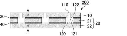
- FIG. 2 is a cross-sectional view schematically showing another example of the sound absorbing member of the present invention.
- the sound absorbing member shown in FIG. 2 is a sound absorbing member having two lower layers.
- the lower layer 20 is composed of two layers of a side layer 21 and a bottom layer 22.
- the side layer 21 is provided with a second through hole 120, and the second through hole 120 is a hollow portion 120.
- a wall surface 121 which is a part of the side layer 21 is a side surface of the hollow portion 120
- a surface 122 of the bottom layer 22 which is a part of the bottom layer 22 is a bottom surface of the hollow portion 120.
- the upper layer 10 and the lower layer 20 are bonded by an adhesive layer 30. Of the layers constituting the lower layer 20, the side layer 21 is adhered to the upper layer 10. An adhesive layer 40 is also provided between the side layer 21 and the bottom layer 22, and the side layer 21 and the bottom layer 22 are also adhered.
- the upper layer 10 is provided with a first through hole 110 forming the introduction passage 110, and the lower layer 20 is provided with a hollow portion 120.
- the introduction passage 110 and the hollow portion 120 form a Helmholtz resonance structure. In the sound absorbing member 200, the introduction passage 110 and the hollow portion 120 are cylindrical.
- the upper layer 10 is a plate material, and a plate-like first through hole 110 is provided in the plate material.
- the side layer 21 and the bottom layer 22 constituting the lower layer 20 are also plate members.
- a cylindrical second through hole 120 is provided in the plate member that constitutes the side layer 21. The through holes are not provided in the plate material constituting the bottom layer 22.
- the sound absorbing member of the present invention has a compressive stress ⁇ of 0.1 to 200 MPa measured in the thickness direction in accordance with JIS K 7181 (2011) at the portion where the Helmholtz resonance structure is not formed.
- ⁇ compressive stress measured in the thickness direction in accordance with JIS K 7181 (2011) at the portion where the Helmholtz resonance structure is not formed.
- the AA line is shown.
- the portion shown by the line AA is a portion where the Helmholtz resonance structure is not formed, and the thickness direction is the direction of the line AA.
- the parts for vehicles of the present invention are characterized by including the sound absorbing member of the present invention.
- the sound absorbing member of the present invention is excellent as a part for vehicles because it is excellent in soundproofing performance.
- a raising member, a partition member, a luggage box, etc. are mentioned.
- An automobile according to the present invention is characterized in that the introduction passage of the sound absorbing member according to the present invention is disposed in the direction of the road surface.
- FIG. 3A is explanatory drawing which shows typically an example of the site
- FIG.3 (b) is partial expansion of the area
- FIG. 3A the automobile 1 includes a luggage room 3 behind the rear seat 2. At the lower part of the luggage room 3, a plate-like floor member 4 is laid, and under the floor member 4, an underfloor space 5 is present. The sound absorbing member 100 is disposed under the underfloor space 5 of the automobile 1 with the introduction passage 110 directed to the road surface.
- One aspect of a method of manufacturing a sound absorbing member according to the present invention is a method of manufacturing a sound absorbing member having a Helmholtz resonance structure including an introduction passage opened on the surface and a hollow portion connected to the outside through the introduction passage. , Producing an upper layer which is a plate material having a columnar first through hole serving as an introduction passage; Producing a lower layer which is a plate material having a hollow portion; Bonding the upper layer and the lower layer with an adhesive layer; The plate material constituting the upper layer is characterized in that the plate material does not have a communication hole formed by foaming.
- This aspect is a method of manufacturing the sound absorbing member in which the lower layer is one layer.
- Step of producing upper layer A plate material of a predetermined thickness made of a material such as a resin that can be used as a plate material is prepared.
- the plate material constituting the upper layer is a plate material having no communicating hole formed by foaming. It is preferable to produce an upper layer by forming a 1st through-hole by machining with respect to the board
- the upper layer can be produced by forming the first through holes with a machining means such as punching, drill, or laser for a plate material having no through holes.
- the foamed resin composed of expandable resin particles (beads) as a plate material
- the upper layer in which the first through hole is provided in the plate material can be manufactured.
- the plate material constituting the upper layer thus obtained is a plate material having no communication hole formed by foaming.
- a plate material of a predetermined thickness made of a material such as a resin that can be used as a plate material is prepared. It is preferable that the board
- a lower layer can be produced by forming a concave portion to be a hollow portion by the middle in the thickness direction of a plate material having no through hole. The diameter of the recess is made larger than the diameter of the first through hole.
- the recess is preferably formed by machining, and cutting with an end mill or processing with a hot wire is preferably used.
- plate material you may integrally mold the board
- a foamed resin comprising expandable resin particles (beads)
- the plate material constituting the lower layer obtained in this manner is a plate material having no communication hole formed by foaming.
- a sheet-like adhesive is prepared according to the shape and position of the recess (hollow part) of the lower layer, and the upper layer and the lower layer are prepared by holding the adhesive between the upper layer and the lower layer. It can be adhered by an adhesive layer.
- the position of the first through hole of the upper layer and the hollow portion (concave portion) of the lower layer are aligned to form a Helmholtz resonance structure.
- the upper layer and the lower layer are adhered by the adhesive layer by applying the adhesive according to the shape and position of the lower concave portion (hollow part), laminating the upper layer and the lower layer, and exerting the adhesive force of the adhesive. it can.
- the conditions for exerting the adhesive strength of the adhesive conditions in accordance with the adhesive characteristics of the adhesive may be used.
- Another aspect of the method of manufacturing a sound absorbing member according to the present invention is a method of manufacturing a sound absorbing member having a Helmholtz resonance structure including an introduction passage opened on the surface and a hollow portion connected to the outside via the introduction passage. , Producing an upper layer which is a plate material having a columnar first through hole serving as an introduction passage; Producing a side layer which is a plate material having a second through hole; Preparing a plate material to be a bottom layer; A plate serving as the upper layer, a plate serving as the side layer, and a plate serving as the bottom layer are stacked to form a hollow portion by the second through hole and the bottom layer, and a lower layer comprising the side layer and the bottom layer is formed.
- the plate material forming the upper layer and the plate material forming the side surface layer are characterized in that they are plate materials having no communication holes formed by foaming.
- This aspect is a method of manufacturing a sound absorbing member having a two-layer lower layer.
- the upper layer can be manufactured in the same manner as in the case where the lower layer is a single-layer sound absorbing member.
- a plate material of a predetermined thickness made of a material such as a resin that can be used as a plate material is prepared.
- the plate material constituting the upper layer is a plate material having no communicating hole formed by foaming. It is preferable to produce an upper layer by forming a 1st through-hole by machining with respect to the board
- the upper layer can be produced by forming the first through holes with a machining means such as punching, drill, or laser for a plate material having no through holes.
- the foamed resin composed of expandable resin particles (beads) as a plate material
- the upper layer in which the first through hole is provided in the plate material can be manufactured.
- the plate material constituting the upper layer thus obtained is a plate material having no communication hole formed by foaming.
- Step of producing side layer A plate material of a predetermined thickness made of a material such as a resin that can be used as a plate material is prepared.
- the plate material constituting the side layer is a plate material having no communicating hole formed by foaming. It is preferable to produce a side layer by forming a 2nd through-hole by machining with respect to the board
- a side surface layer can be produced by forming the second through holes with a machining means such as punching, drill, or laser for a plate material having no through holes. The diameter of the second through hole is made larger than that of the first through hole.
- a foamed resin composed of expandable resin particles (beads) as a plate material
- projections may be provided in the mold to form the second through holes, and the expandable resin particles may be foamed, too.
- a side layer in which the second through hole is provided in the plate material can be manufactured.
- the plate material constituting the side layer obtained in this manner is a plate material having no communication hole formed by foaming.
- Step of preparing plate material to be bottom layer A plate made of a material such as resin that can be used as a plate and having a predetermined thickness without a through hole is prepared. It is preferable that the board
- a plate serving as the upper layer, a plate serving as the side layer, and a plate serving as the bottom layer are laminated. At this time, an adhesive layer is provided between at least the upper plate and the side plate.
- the adhesive layer may or may not be provided between the plate serving as the side layer and the plate serving as the bottom layer.
- a sheet-like adhesive agent is prepared in accordance with the shape and position of the second through hole and prepared, and the adhesive force of the adhesive agent is exhibited by sandwiching it between the plate material as the upper layer and the plate material as the side layer.
- the upper layer and the side layer (lower layer) can be adhered by the adhesive layer.
- an adhesive according to the shape and position of the second through hole (hollow part) of the plate material to be the side layer and laminate the upper layer and the side layer (lower layer) to exert the adhesive force of the adhesive.
- the upper layer and the side layer (lower layer) can be adhered by the adhesive layer.
- an adhesive may be applied to adhere to the bottom layer in accordance with the shape and position of the second through holes of the plate material to be the side layer.
- the upper plate material, the side plate material, and the bottom plate layer may be laminated in three layers at one time, and the side plate may be a plate material and the upper plate material or a bottom plate material The first two layers may be stacked before the remaining one layer may be stacked.
- FIG. 4 is a perspective view schematically showing an example of the method of manufacturing a sound absorbing member of the present invention.
- FIG. 4 schematically shows a method of manufacturing a sound absorbing member in which the lower layer is a single layer.
- the upper layer 10 and the lower layer 20 are laminated via the adhesive layer 30.
- a first through hole 110 is formed in the upper layer 10
- a hollow portion 120 is formed in the lower layer 20.
- the adhesive layer 30 is an adhesive on a sheet, and has through holes 130 which are cut out in accordance with the shape of the hollow portion.
- the upper layer 10 and the lower layer 20 are laminated via the adhesive layer 30 and adhered to obtain the sound absorbing member 100 shown in FIG.
- the position of the first through hole 110 is adjusted to the position of the hollow portion 120 and the position of the through hole 130 of the adhesive layer. If the adhesive layer is formed on the upper surface of the hollow portion, the soundproofing characteristics may change, which is not preferable.
- FIG. 5 is a perspective view schematically showing another example of the method of manufacturing a sound absorbing member of the present invention.
- FIG. 5 schematically shows a method of manufacturing a sound absorbing member having two lower layers.
- the upper layer 10 and the side layer 21 are laminated via the adhesive layer 30.
- the side layer 21 and the bottom layer 22 are laminated via the adhesive layer 40.
- a first through hole 110 is formed in the upper layer 10
- a second through hole 120 is formed in the side layer 21.
- the adhesive layer 30 is an adhesive on the sheet and has through holes 130 which are cut out in accordance with the shape of the second through holes.
- the bottom layer 22 is not provided with a through hole.
- the adhesive layer 40 is an adhesive on the sheet and has through holes 140 which are cut out in accordance with the shape of the second through holes.
- the sound absorbing member 200 shown in FIG. 2 is obtained by laminating the upper layer 10, the side layer 21, and the bottom layer 22 via the adhesive layer 30 and the adhesive layer 40 and adhering them. At this time, the position of the first through hole 110, the position of the through hole 130 of the adhesive layer 30, the position of the second through hole 120, and the position of the through hole 140 of the adhesive layer 40 are adjusted. If the adhesive layer is formed on the bottom and / or top of the hollow portion, the soundproofing properties may change, which is not preferable.
- FIGS. 4 and 5 although a sheet-like adhesive layer is used to bond the upper layer and the lower layer, the sound absorbing member of the present invention is manufactured by a method of applying an adhesive between the upper layer and the lower layer. You may
- Example 1 Preparation of Plate Material Primary foam particles (made of polypropylene, average particle diameter: 3.5 mm, foaming agent: carbon dioxide) prepared by prefoaming foamable resin particles are filled in a mold and foam molding is performed by heating steam (143) C. for 10 seconds, removed from the mold, and dried at 80.degree. C. for 12 hours to prepare three plate members of 100 mm long x 100 mm wide x 10 mm thick made of a foamed resin. At this time, the expansion ratio of the foamed resin was 30 times.
- the plate was a plate made of foamable resin particles (beads) and was a plate not having a communicating hole formed by foaming.
- a through hole (first through hole) having a diameter of 3 mm so as to form a staggered arrangement of the hole pitch of 10 mm in one of the plate members having a thickness of 10 mm manufactured in the above (1) Were drilled to produce the upper layer.
- a circular through hole (second through hole) having a diameter of 10 mm is formed by drilling in another 10 mm thick plate material manufactured in the above (1) so as to form a staggered arrangement of the hole pitch 10 mm.
- the side layer was made.
- the other one of the plate members having a thickness of 10 mm manufactured in the above (1) was not processed but was used as a bottom layer.
- a silicone rubber (a silicone rubber sheet having a hardness of 30 manufactured by Kyowa Kogyo Co., Ltd. and having a thickness of 10 mm) having no communicating holes formed by foaming was prepared.
- the upper plate, the side layer and the bottom layer were prepared in the same manner as in Example 1 in the thickness of each plate material and the dimensions of the through holes, and the respective layers were adhered in the same manner as in Example 1 to obtain a sound absorbing member according to Comparative Example 1. .
- a foam urethane (Carmflex F2 manufactured by Inoac, Inc., having a communicating hole made by blowing a gas in addition to a foaming agent) and having a thickness of 10 mm was prepared.
- the thickness of the plate and the dimensions of the through holes were the same as in Example 1 to produce the upper layer, the side layer and the bottom layer, and the respective layers were adhered in the same manner as in Example 1 to obtain a sound absorbing member according to Comparative Example 2.
- a plate material which is a polyurethane resin having communicating holes formed by foaming was produced.
- the mold to be molded is a cylinder A having a length of 100 mm ⁇ 100 mm ⁇ 10 mm thick and a cylinder 10 mm in diameter for forming a plate 100 mm ⁇ 100 mm ⁇ 20 mm thick.
- two types of mold B provided with a convex portion having a height of 10 mm.
- a plate A having a thickness of 10 mm having a communicating hole is obtained by the mold A, a cylindrical recess is provided by the die B, and a plate B having a communicating hole is obtained.
- An adhesive (Hondo G Clear manufactured by Konishi, application thickness: 70 ⁇ m) was applied to a portion of the plate B where the recess was not provided, and the plate A was adhered to obtain a sound absorbing member according to Comparative Example 3.
- Comparative example 4 A glass epoxy resin (made by Kokgo Co., Ltd., 107-176) having no communicating holes formed by foaming as a plate material and having a thickness of 10 mm was prepared. The thickness of the plate and the dimensions of the through holes were the same as in Example 1 to produce the upper layer, the side layer and the bottom layer, and the respective layers were adhered in the same manner as in Example 1 to obtain a sound absorbing member according to Comparative Example 4.
- Comparative example 5 A sound absorbing member according to Comparative Example 5 was obtained in the same manner as Example 1, but fixing the outer periphery with a U-shaped cross-section fastener without bonding the layers.
- Example 1 0.7 MPa Comparative Example 1: 0.056 MPa Comparative example 2: 0.006 MPa Comparative example 3: 37 MPa Comparative example 4: 215 MPa Comparative example 5: 0.5 MPa
- FIG. 6 is an explanatory view schematically showing an outline of a confirmation test of the secondary radiation sound.
- the secondary radiation sound measurement device 80 is a metal pipe (inner diameter 30 mm, length: 50 mm), and receives sound through the sound source room 81 for generating sound from the speaker 83 and the sound absorbing member 100 as a test body
- a chamber 82 is provided.
- the sound receiving chamber 82 is provided with a sound receiving chamber side microphone 85 so that the sound pressure level measured by the sound receiving chamber side microphone 85 can be taken into the measuring device 86.
- the speaker produced a sound of 120 dB at 100 to 1200 Hz and the transmission loss measurement was performed. At this time, it was measured whether or not the sound at less than 300 Hz was captured, and if the sound at less than 300 Hz was captured, it was determined that the secondary radiation sound was generated. In addition, since a drop in transmission loss is observed when the secondary radiation sound is generated, it can be determined that the secondary report sound insulation is generated when this drop is present.
- Example 7 (a), 7 (b), 7 (c), 7 (d), 7 (e) and 7 (f) respectively correspond to Example 1 and Comparative Examples 1 to 5.
- 5 is a graph showing the relationship between frequency and transmission loss.
- a circle is drawn by a broken line at a position where the drop of the transmission loss is observed.
- Example 1 there was no drop in transmission loss between 100 and 1200 Hz, and no secondary radiation sound was confirmed.
- Comparative Examples 1, 4 and 5 a drop in transmission loss was observed between 100 and 1200 Hz, and secondary radiation was confirmed.
- Comparative Examples 2 and 3 there was no drop in transmission loss, and no secondary radiation sound was confirmed.
- Example 1 and Comparative Examples 1 and 4 when the constituent material of the sound absorbing member does not have the communication hole formed by foaming, and does not satisfy the condition of predetermined compressive strength, the secondary radiation noise Are understood to occur. Further, it is understood from the comparison between Example 1 and Comparative Example 5 that the generation of the secondary radiation noise can not be prevented unless the upper layer and the lower layer are adhered. Further, it is understood that the sound absorbing member of Comparative Example 3 has a communicating hole formed by foaming in its constituent material, and the secondary radiation sound is not generated in the first place.
- Reference Signs List 1 car 2 back seat 3 luggage room 4 floor member 5 floor space 80 secondary radiation sound measuring device 81 sound source chamber 82 sound receiving chamber 83 speaker 85 sound receiving room microphone 86 measuring device 100 200 sound absorbing member 10 upper layer 20 lower layer 21 side surface Layer 22 Bottom layer 30, 40 Adhesive layer 110 Introduction passage (first through hole) 120 Hollow part (second through hole) 121 Wall surface of second through hole (side surface of hollow portion) 122 Bottom layer surface (bottom of hollow) 130, 140 adhesive layer through holes
Landscapes
- Physics & Mathematics (AREA)
- Engineering & Computer Science (AREA)
- Acoustics & Sound (AREA)
- Multimedia (AREA)
- Mechanical Engineering (AREA)
- Soundproofing, Sound Blocking, And Sound Damping (AREA)
- Vehicle Interior And Exterior Ornaments, Soundproofing, And Insulation (AREA)
- Laminated Bodies (AREA)
Abstract
L'invention concerne un élément absorbant acoustique qui possède une structure de résonance de Helmholtz constituée d'une partie vide connectée à un trajet d'introduction ouvert en surface et à une partie externe via ledit trajet d'introduction. Cet élément absorbant acoustique est caractéristique en ce qu'il est constitué : d'une couche supérieure qui est à son tour constituée d'un matériau plaque exempt de trous continus formés par une mousse, et sur laquelle sont agencés des premiers trous débouchant de forme colonnaire formant ledit trajet d'introduction ; d'une couche inférieure qui est stratifiée sur ladite couche supérieure, et sur laquelle est agencée ladite partie vide ; et d'une couche d'adhésif mettant en adhésion ladite couche supérieure et ladite couche inférieure. Dans une portion dudit élément absorbant acoustique dans laquelle la structure de résonance de Helmholtz n'est pas formée, la contrainte de compression mesurée dans la direction de l'épaisseur conformément à JIS K 7181(2011), est comprise entre 0,1 et 200MPa.
Priority Applications (2)
| Application Number | Priority Date | Filing Date | Title |
|---|---|---|---|
| PCT/JP2017/027545 WO2019021480A1 (fr) | 2017-07-28 | 2017-07-28 | Élément absorbant acoustique ainsi que procédé de fabrication de celui-ci, composant pour véhicule, et automobile |
| JP2019532341A JPWO2019021480A1 (ja) | 2017-07-28 | 2017-07-28 | 吸音部材、車両用部品、自動車及び吸音部材の製造方法 |
Applications Claiming Priority (1)
| Application Number | Priority Date | Filing Date | Title |
|---|---|---|---|
| PCT/JP2017/027545 WO2019021480A1 (fr) | 2017-07-28 | 2017-07-28 | Élément absorbant acoustique ainsi que procédé de fabrication de celui-ci, composant pour véhicule, et automobile |
Publications (1)
| Publication Number | Publication Date |
|---|---|
| WO2019021480A1 true WO2019021480A1 (fr) | 2019-01-31 |
Family
ID=65039491
Family Applications (1)
| Application Number | Title | Priority Date | Filing Date |
|---|---|---|---|
| PCT/JP2017/027545 Ceased WO2019021480A1 (fr) | 2017-07-28 | 2017-07-28 | Élément absorbant acoustique ainsi que procédé de fabrication de celui-ci, composant pour véhicule, et automobile |
Country Status (2)
| Country | Link |
|---|---|
| JP (1) | JPWO2019021480A1 (fr) |
| WO (1) | WO2019021480A1 (fr) |
Cited By (2)
| Publication number | Priority date | Publication date | Assignee | Title |
|---|---|---|---|---|
| TWI850021B (zh) * | 2023-07-11 | 2024-07-21 | 國立成功大學 | 吸音結構 |
| US12406649B2 (en) | 2023-07-18 | 2025-09-02 | National Cheng Kung University | Acoustic metasurface structure |
Citations (3)
| Publication number | Priority date | Publication date | Assignee | Title |
|---|---|---|---|---|
| JPS5952299A (ja) * | 1982-09-17 | 1984-03-26 | 松下電器産業株式会社 | 空気調和機の吸音装置 |
| JPH1039875A (ja) * | 1996-07-19 | 1998-02-13 | Mitsubishi Heavy Ind Ltd | 遮音材構造および空気調和機の防音構造 |
| JP2012255967A (ja) * | 2011-06-10 | 2012-12-27 | Aisin Chemical Co Ltd | 熱硬化防音塗料組成物 |
Family Cites Families (4)
| Publication number | Priority date | Publication date | Assignee | Title |
|---|---|---|---|---|
| JPS515424A (en) * | 1974-07-04 | 1976-01-17 | Nissan Diesel Motor Co | Enjinruumuno kyuonsochi |
| JP2000034937A (ja) * | 1998-07-17 | 2000-02-02 | Mitsubishi Motors Corp | 吸音装置 |
| JP2006199276A (ja) * | 2004-12-24 | 2006-08-03 | Kobe Steel Ltd | 吸音構造 |
| JP6588324B2 (ja) * | 2015-12-11 | 2019-10-09 | 小島プレス工業株式会社 | 車両用樹脂製外装品 |
-
2017
- 2017-07-28 WO PCT/JP2017/027545 patent/WO2019021480A1/fr not_active Ceased
- 2017-07-28 JP JP2019532341A patent/JPWO2019021480A1/ja active Pending
Patent Citations (3)
| Publication number | Priority date | Publication date | Assignee | Title |
|---|---|---|---|---|
| JPS5952299A (ja) * | 1982-09-17 | 1984-03-26 | 松下電器産業株式会社 | 空気調和機の吸音装置 |
| JPH1039875A (ja) * | 1996-07-19 | 1998-02-13 | Mitsubishi Heavy Ind Ltd | 遮音材構造および空気調和機の防音構造 |
| JP2012255967A (ja) * | 2011-06-10 | 2012-12-27 | Aisin Chemical Co Ltd | 熱硬化防音塗料組成物 |
Cited By (2)
| Publication number | Priority date | Publication date | Assignee | Title |
|---|---|---|---|---|
| TWI850021B (zh) * | 2023-07-11 | 2024-07-21 | 國立成功大學 | 吸音結構 |
| US12406649B2 (en) | 2023-07-18 | 2025-09-02 | National Cheng Kung University | Acoustic metasurface structure |
Also Published As
| Publication number | Publication date |
|---|---|
| JPWO2019021480A1 (ja) | 2020-05-28 |
Similar Documents
| Publication | Publication Date | Title |
|---|---|---|
| US11505137B2 (en) | Sound absorption member, vehicle component, and automobile | |
| US8157051B2 (en) | Moulded soundproofing component, and manufacturing method thereof | |
| KR101874305B1 (ko) | 차량용 플로워카페트 및 그의 제조방법 | |
| EP1463863A1 (fr) | Stratifies a densite multiple attenuant le son et leurs procedes de fabrication | |
| JP6982972B2 (ja) | 積層体 | |
| WO2019026294A1 (fr) | Élément d'absorption sonore, composant de véhicule et automobile | |
| JP2020007975A (ja) | コンプレッサー用防音材 | |
| JPWO2020084802A1 (ja) | 自動車用遮音材 | |
| CN109952608A (zh) | 声学泡沫去耦器 | |
| US10569500B2 (en) | Method for producing an automotive equipment part and associated part | |
| CN111417510A (zh) | 用于振动阻尼和/或声音衰减材料的制造的方法 | |
| JP6916878B2 (ja) | 吸音材、車両用部品及び自動車 | |
| WO2019021480A1 (fr) | Élément absorbant acoustique ainsi que procédé de fabrication de celui-ci, composant pour véhicule, et automobile | |
| WO2019021478A1 (fr) | Structure insonore, composant pour véhicule, et automobile | |
| JP6916879B2 (ja) | 防音構造体、車両用部品及び自動車 | |
| Jonza et al. | Acoustically absorbing lightweight thermoplastic honeycomb panels | |
| JP4079851B2 (ja) | 防音材 | |
| WO2019021477A1 (fr) | Élément absorbant acoustique, composant pour véhicule, et automobile | |
| JP4359177B2 (ja) | 防音性を付与した車両用下肢部衝撃吸収パッド | |
| JP2018158691A (ja) | 車両用吸音材、車両用部品、自動車及び自動車用仕切り部材 | |
| JP2020008684A (ja) | 防音構造体 | |
| KR102516518B1 (ko) | 자동차용 대쉬 인슐레이터 및 이의 제조방법 | |
| JP4393880B2 (ja) | 薄幅溝を有する合成樹脂発泡成形体 | |
| KR20240074485A (ko) | 단일소재를 이용한 차량용 트렁크 내장재 및 그 제조방법 | |
| JP2006088737A (ja) | 衝撃吸収構造体および衝撃吸収構造体の製造方法 |
Legal Events
| Date | Code | Title | Description |
|---|---|---|---|
| 121 | Ep: the epo has been informed by wipo that ep was designated in this application |
Ref document number: 17919565 Country of ref document: EP Kind code of ref document: A1 |
|
| ENP | Entry into the national phase |
Ref document number: 2019532341 Country of ref document: JP Kind code of ref document: A |
|
| NENP | Non-entry into the national phase |
Ref country code: DE |
|
| 122 | Ep: pct application non-entry in european phase |
Ref document number: 17919565 Country of ref document: EP Kind code of ref document: A1 |