WO2019021491A1 - Dispositif de réglage de hauteur de véhicule - Google Patents
Dispositif de réglage de hauteur de véhicule Download PDFInfo
- Publication number
- WO2019021491A1 WO2019021491A1 PCT/JP2017/027957 JP2017027957W WO2019021491A1 WO 2019021491 A1 WO2019021491 A1 WO 2019021491A1 JP 2017027957 W JP2017027957 W JP 2017027957W WO 2019021491 A1 WO2019021491 A1 WO 2019021491A1
- Authority
- WO
- WIPO (PCT)
- Prior art keywords
- oil
- cylinder
- piston
- vehicle height
- damper
- Prior art date
- Legal status (The legal status is an assumption and is not a legal conclusion. Google has not performed a legal analysis and makes no representation as to the accuracy of the status listed.)
- Ceased
Links
Images

Classifications
-
- B—PERFORMING OPERATIONS; TRANSPORTING
- B60—VEHICLES IN GENERAL
- B60G—VEHICLE SUSPENSION ARRANGEMENTS
- B60G17/00—Resilient suspensions having means for adjusting the spring or vibration-damper characteristics, for regulating the distance between a supporting surface and a sprung part of vehicle or for locking suspension during use to meet varying vehicular or surface conditions, e.g. due to speed or load
- B60G17/02—Spring characteristics, e.g. mechanical springs and mechanical adjusting means
- B60G17/04—Spring characteristics, e.g. mechanical springs and mechanical adjusting means fluid spring characteristics
- B60G17/056—Regulating distributors or valves for hydropneumatic systems
- B60G17/0565—Height adjusting valves
-
- B—PERFORMING OPERATIONS; TRANSPORTING
- B60—VEHICLES IN GENERAL
- B60G—VEHICLE SUSPENSION ARRANGEMENTS
- B60G17/00—Resilient suspensions having means for adjusting the spring or vibration-damper characteristics, for regulating the distance between a supporting surface and a sprung part of vehicle or for locking suspension during use to meet varying vehicular or surface conditions, e.g. due to speed or load
- B60G17/06—Characteristics of dampers, e.g. mechanical dampers
- B60G17/08—Characteristics of fluid dampers
-
- B—PERFORMING OPERATIONS; TRANSPORTING
- B60—VEHICLES IN GENERAL
- B60G—VEHICLE SUSPENSION ARRANGEMENTS
- B60G13/00—Resilient suspensions characterised by arrangement, location or type of vibration dampers
- B60G13/02—Resilient suspensions characterised by arrangement, location or type of vibration dampers having dampers dissipating energy, e.g. frictionally
- B60G13/06—Resilient suspensions characterised by arrangement, location or type of vibration dampers having dampers dissipating energy, e.g. frictionally of fluid type
-
- F—MECHANICAL ENGINEERING; LIGHTING; HEATING; WEAPONS; BLASTING
- F16—ENGINEERING ELEMENTS AND UNITS; GENERAL MEASURES FOR PRODUCING AND MAINTAINING EFFECTIVE FUNCTIONING OF MACHINES OR INSTALLATIONS; THERMAL INSULATION IN GENERAL
- F16F—SPRINGS; SHOCK-ABSORBERS; MEANS FOR DAMPING VIBRATION
- F16F9/00—Springs, vibration-dampers, shock-absorbers, or similarly-constructed movement-dampers using a fluid or the equivalent as damping medium
- F16F9/32—Details
- F16F9/50—Special means providing automatic damping adjustment, i.e. self-adjustment of damping by particular sliding movements of a valve element, other than flexions or displacement of valve discs; Special means providing self-adjustment of spring characteristics
- F16F9/512—Means responsive to load action, i.e. static load on the damper or dynamic fluid pressure changes in the damper, e.g. due to changes in velocity
- F16F9/5126—Piston, or piston-like valve elements
-
- B—PERFORMING OPERATIONS; TRANSPORTING
- B60—VEHICLES IN GENERAL
- B60G—VEHICLE SUSPENSION ARRANGEMENTS
- B60G2202/00—Indexing codes relating to the type of spring, damper or actuator
- B60G2202/20—Type of damper
- B60G2202/24—Fluid damper
-
- B—PERFORMING OPERATIONS; TRANSPORTING
- B60—VEHICLES IN GENERAL
- B60G—VEHICLE SUSPENSION ARRANGEMENTS
- B60G2202/00—Indexing codes relating to the type of spring, damper or actuator
- B60G2202/40—Type of actuator
- B60G2202/41—Fluid actuator
- B60G2202/413—Hydraulic actuator
-
- B—PERFORMING OPERATIONS; TRANSPORTING
- B60—VEHICLES IN GENERAL
- B60G—VEHICLE SUSPENSION ARRANGEMENTS
- B60G2300/00—Indexing codes relating to the type of vehicle
- B60G2300/12—Cycles; Motorcycles
- B60G2300/122—Trikes
-
- B—PERFORMING OPERATIONS; TRANSPORTING
- B60—VEHICLES IN GENERAL
- B60G—VEHICLE SUSPENSION ARRANGEMENTS
- B60G2500/00—Indexing codes relating to the regulated action or device
- B60G2500/30—Height or ground clearance
Definitions
- the present invention relates to a vehicle height adjusting device that adjusts a vehicle height by causing oil to flow into or from a damper device.
- the vehicle height adjustment device as disclosed in Patent Document 1 includes a cylindrical body attached to a vehicle body and having a cylindrical shape, an operation unit rotatably provided to the cylindrical body, and a cylinder by the operation portion. It has a piston provided so as to be movable along the axis, and a damper device into which oil that has flowed out of the cylinder when the piston moves. Two damper devices are provided to sandwich the wheel.
- the control unit When raising the vehicle height, the control unit is rotated to move the piston forward. As the piston advances, oil is sent to each damper device. The oil sent to the damper device can push down the piston in the damper device to raise the vehicle height. When lowering the vehicle height, the operation unit is rotated to retract the piston. The piston in the damper device is pushed up by the biasing force of the spring provided in the damper device, and the vehicle height can be lowered.
- An object of the present invention is to provide a technology capable of making the amount of oil flowing into each damper device and the amount of oil flowing out of each damper device more uniform while using one operating unit. Do.
- the inside is divided into a plurality of oil chambers by partitions attached to the vehicle body and having a tubular shape and provided along the axis, the oil chambers are filled with the oil, and each of the oil chambers is And a cylinder provided with a cylinder oil hole connected to the outside, One operation unit rotatably provided on the cylinder and movable along the axis by rotating the cylinder; Pistons that are movable along the axis by the operation unit and are stored in the respective oil chambers; A damper oil hole through which the oil flowing out from the cylinder oil hole flows when the piston moves is provided, and the height of the vehicle can be adjusted by the amount of the oil filled through the damper oil hole.
- a vehicle height adjusting device comprising: a plurality of damper devices capable of absorbing impact energy input to a wheel.
- the inside of the cylinder is divided into a plurality of oil chambers, and a piston is provided in each of the oil chambers.
- Each oil chamber is connected to the damper device so that the filled oil can flow in and out.
- Each piston is connected to one operating part and is moved along the axis by this operating part.
- the amount of movement of each piston can be made the same.
- the amount of oil flowing out of the oil chamber and flowing into the oil chamber is determined by the amount of movement of the piston. Therefore, by making the amount of movement of the piston the same, the amount of oil flowing into and out of the oil chamber can also be made the same. Therefore, according to the present invention, the amount of oil flowing into each of the damper devices and the amount of oil flowing out of each of the damper devices can be made more uniform while being one operation unit.
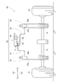
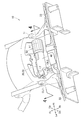
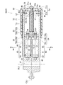
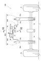
- FIG. 1 is a perspective view of a three-wheeled vehicle equipped with a vehicle height adjustment device according to a first embodiment of the present invention as viewed obliquely from the right rear. It is the figure which showed typically the vehicle height adjustment apparatus shown in FIG. It is the figure which expanded the principal part of FIG.
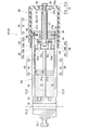
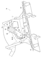
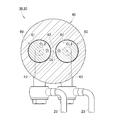
- FIG. 5 is a cross-sectional view taken along line 4-4 of FIG. 3; It is a figure explaining the vehicle height adjustment apparatus of the state which made the cylinder and the operation part which were shown in FIG. 3 swing. It is a figure explaining the vehicle height adjustment device at the time of operating the operation part shown in FIG.
- FIG. 7 is a cross-sectional view taken along line 7-7 of FIG. 6; It is the figure which showed typically the vehicle height adjustment apparatus by Example 2 of this invention. It is the figure which showed typically the vehicle height adjustment apparatus by Example 3 of this invention.
- FIG. 10 is a cross-sectional view taken along line 10-10 of FIG. 9;
- the left and right refer to the left and right with respect to the occupant of the tricycle
- the front and back refer to the front and back with respect to the traveling direction of the tricycle.
- Fr indicates the front
- Rr indicates the rear
- Le indicates the occupant's left
- Ri indicates the occupant's right
- Up indicates the upper
- Dn indicates the lower.
- the vehicle height adjustment device 20 is mounted on, for example, a three-wheeled vehicle 10 (saddle-ride type vehicle 10) which a passenger straddles and gets on.
- the three-wheeled vehicle 10 is supported by a vehicle body 11, a vehicle height adjustment device 20 supported by the vehicle body 11 and capable of adjusting the vehicle height, and left and right damper devices 22 and 22 constituting a part of the vehicle height adjustment device 20.
- a seat 16 to be seated The front end of the seat 16 is fixed to the vehicle body 11, and the seat 16 is supported swingably in the front-rear direction.
- the vehicle height adjustment device 20 includes a hydraulic pressure adjustment unit 30 operated by a passenger to adjust the hydraulic pressure, left and right damper devices 22 and 22 in which the filling amount of oil is adjusted by the operation of the hydraulic pressure adjustment unit 30, Tube-shaped left and right connection members 23, 23 are provided to connect the left and right damper devices 22, 22 to the hydraulic pressure adjustment unit 30.
- the hydraulic pressure adjustment unit 30 is mounted on the vehicle body 11 in a swingable manner and has one end closed.
- the hydraulic adjustment unit 30 is rotatably provided on the cylindrical body 40 and is movable along the axis line CL1 of the cylindrical body 40 by rotation.
- a click mechanism 70 for allowing the occupant to recognize the rotation of the operation unit 50, with a part housed in the nut member 37 and the pocket 37a formed on the outer periphery of the nut member 37.
- the cylindrical body 40 has a through hole 41 at one end through which the shaft member 17 for fixing to the vehicle body 11 penetrates.
- the through hole 41 is opened perpendicularly to the axis line CL1.
- the cylindrical body 40 is provided swingably in the vehicle left-right direction centering on the axis line CL3 of the shaft member 17. That is, the cylinder 40 is swingably supported by the vehicle body 11 via the shaft member 17.
- the cylinder 40 can swing leftward and upward from the state shown in FIG.
- the state shown in FIG. 3 can be referred to as the collapsed state of the cylinder 40.
- the cylindrical body 40 is a cylindrical part whose one end is closed.
- the cylinder 40 is provided along the axis line CL1 and has a partition 42 for dividing the inside into two oil chambers Oi, Oi, and dampers 22, 22 (see FIG. 2) provided at the tips of the respective oil chambers Oi, Oi.
- the cylindrical oil holes 43 and 43 to be connected, the screw insertion hole 44 through which the screw 36 passes from the side surface of the other end, and the click mechanism insertion hole 45 through which the click mechanism 70 penetrates from the side surface to the inside of the other end
- a ring fitting groove 46 formed in the shape of a groove around the entire inner periphery of the other end and into which the stopper ring 39 is fitted.
- the two oil chambers Oi, Oi are each formed in a cylindrical shape of the same size.
- the oil chambers Oi, Oi are filled with oil, and the tips of the pistons 60, 60 are accommodated.
- the cylindrical oil holes 43, 43 are cylindrical holes smaller in diameter than the oil chambers Oi, Oi.
- the cylindrical oil holes 43, 43 are both opened downward. That is, the ends on the outer side of the cylindrical oil holes 43, 43 both face the lower part of the cylindrical body 40. It can be said that the cylinder oil holes 43, 43 are provided close to each other.
- the operating portion 50 has a cap shape, and a handle portion 51 rotatably covered on the other end of the cylindrical body 40, and a bolt fixed to the center of the handle portion 51 and screwed at its tip to the nut member 37 Member 52, a cap member 53 having a diameter larger than that of the bolt member 52 attached to the end of the bolt member 52, an operating portion nut 54 fixing the cap member 53 to the bolt member 52, and It has an operating portion screw 55 fixed to the handle portion 51, and an operating portion washer 56 which is sandwiched between the operating portion screw 55 and the bolt member 52 and has a diameter larger than that of the bolt member 52.
- the handle portion 51 has a disc-like handle bottom portion 51a provided perpendicularly to the axis line CL1, and a handle side wall portion 51b extending along the side surface of the cylinder 40 from the periphery of the handle bottom portion 51a.
- the handle bottom 51a has, at its center, a bolt storage hole 51c in which the bolt head 52a of the bolt member 52 is stored.
- a large number of handle groove portions 73 formed in a groove shape in parallel with the axis line CL1 are formed on the inner periphery of the handle side wall portion 51b.
- the handle groove 73 constitutes a part of the click mechanism 70. Details will be described later.
- the bolt member 52 can adopt a part obtained by processing the tip of a flanged hexagonal bolt.
- the bolt member 52 is screwed with a bolt head 52a facing the handle bottom 51a, a bolt flange 52b radially extended from the lower end of the bolt head 52a, and a nut member 37 extending from the lower end of the bolt flange 52b.
- a second screw portion 52e a second screw portion 52e.
- the centers of the bolt head 52a, the bolt flange portion 52b and the first screw portion 52c are formed in a female screw shape so that the operating portion screw 55 can be screwed.
- the bolt small diameter portion 52d is smaller in diameter than the first screw portion 52c. For this reason, the boundary between the first screw portion 52c and the bolt small diameter portion 52d is formed in a step-like shape.
- the cap member 53 is restricted from moving toward the bolt head 52 a by a step.
- the tip of the second screw portion 52e is expanded in diameter by being crushed.
- the distal end of the second screw portion 52e has an expanded diameter, thereby suppressing the falling of the operating portion nut 54.
- the cap member 53 includes a cap large diameter portion 53a in contact with the tip of the first screw portion 52c, and a cap small diameter portion 53b formed at the tip of the cap large diameter portion 53a and having a diameter smaller than that of the cap large diameter portion 53a. have.
- the cap large diameter portion 53 a is in surface contact with the load transfer portion 34.
- the cap small diameter portion 53b penetrates the center of the load transfer portion 34 having a donut shape.
- the operation part washer 56 is a donut plate-like part. The outer circumferential end of the operation part washer 56 is in contact with the handle bottom 51a.
- the piston 60 includes a cylindrical piston main body 61 housed in the oil chamber Oi, a seal member 62 fitted in a piston groove 61a formed at one end of the piston main body 61, and an operating portion from the other end of the piston main body 61 And a piston projection 63 projecting toward 50.
- the seal member 62 is in close contact with the inner wall of the oil chamber Oi, and suppresses the leakage of oil to the operation unit 50 side.
- the piston projection 63 has a cylindrical shape and penetrates the holding member 35. The tips of the piston projections 63 are in contact with the load transfer unit 34, respectively.
- the load transfer unit 34 includes a donut plate-shaped first washer 34 a in surface contact with the cap member 53 (operation unit 50), and a Teflon (registered trademark) Teflon layer applied to the surface of the first washer 34 a. And 34b, and a second washer 34c stacked on the Teflon layer 34b and in contact with the pistons 60, 60.
- the first washer 34a has smaller frictional resistance to the cap member 53 than the second washer 34c.
- the second washer 34 c is a donut plate-like part, and is thicker than the first washer 34 a. In addition, the second washer 34c has higher bending rigidity than the first washer 34a.
- the holding member 35 is formed of a metal plate.
- the holding member 35 has a disk-shaped holding member bottom 35a provided perpendicularly to the axis line CL1, and a holding member wall 35b extending from the periphery of the holding member bottom 35a.
- the holding member bottom portion 35a has a central hole 35c provided at the center, and holding holes 35d, 35d for holding the penetrating piston projection 63.
- the holding member wall 35 b extends from the holding member bottom 35 a toward the other end of the cylindrical body 40 and is in contact with the inner circumferential surface of the cylindrical body 40.
- the nut members 37 are respectively opened from the outer peripheral surface toward the axis line CL1 and include a pocket 37a for housing a part of the click mechanism 70, and a nut portion screw hole 37b formed in a female screw shape so that the screw 36 can be screwed. Have.
- the pockets 37a are provided at two positions on the outer periphery of the nut member 37, mutually offset by 180 °.
- the nut portion screw holes 37 b are provided at three positions on the outer periphery of the nut member 37, mutually offset by 120 °.
- the click mechanism 70 includes a spring 71 housed in the pocket 37a, a ball 72 made of steel balls urged toward the handle portion 51 by the spring 71, and a ball 72 formed on the inner periphery of the handle portion 51. And a handle groove 73.
- the stopper ring 39 can adopt, for example, a C-shaped ring exhibiting a C-shape.
- the stopper ring 39 is fitted in the ring fitting groove 46 by facing the ring fitting groove 46 in a state where the stopper ring 39 is bent toward the center and eliminating the bending.
- the left and right damper devices 22, 22 have the same configuration.
- the left and right damper devices 22, 22 may employ known damper devices capable of adjusting the vehicle height. That is, it has vehicle height adjustment pistons 22a and 22a which are pushed down by oil being sent from the hydraulic pressure adjustment unit 30.
- the height adjustment pistons 22a, 22a are each biased upward by a biasing member. When the height adjustment pistons 22a, 22a are raised by the biasing force of the biasing member, the oil in the damper device is returned to the hydraulic pressure adjustment unit 30 from the damper oil hole 22b.
- connection members 23, 23 can be constituted by known tubes.
- the connection members 23 connect the cylinder oil holes 43 (see FIG. 4) to the damper oil holes 22b, respectively.
- the hydraulic pressure adjustment unit 30 swings to the left centering on the shaft member 17.
- the handle portion 51 is exposed to the outside of the vehicle body 11 from a portion surrounded by the vehicle body 11.
- the occupant rotates the handle portion 51.
- the handle portion 51 In the state shown in FIG. 4, the handle portion 51 is located at the reverse limit.
- the bolt member 52 When the handle portion 51 is rotated from this state, the bolt member 52 is rotated together with the handle portion 51 and is advanced toward the cylindrical oil hole 43 side.
- the cap member 53 When the bolt member 52 is advanced, the cap member 53 is advanced, and the load transfer unit 34 is also advanced.
- the load for advancing the bolt member 52 is transmitted to the pistons 60, 60 via the load transfer unit 34.
- the pistons 60, 60 move forward in the oil chambers Oi, Oi, respectively.
- the pistons 60, 60 are in contact with the load transfer unit 34, respectively. Therefore, the amount of advancement of the pistons 60, 60 is the same as the amount of advancement of the bolt member 52.
- connection members 23, 23 are fed into the damper devices 22, 22, the vehicle height adjustment pistons 22a, 22a are pushed down. This raises the vehicle height.
- the handle portion 51 when lowering the vehicle height, the handle portion 51 is reversely rotated to move backward.
- the height adjustment pistons 22a, 22a are pushed up by the biasing force of the biasing members in the damper devices 22, 22. This lowers the vehicle height.
- the pistons 22a, 22a are pushed up, the oil returns to the inside of the hydraulic pressure adjustment unit 30 via the connection members 23, 23.
- the ball 72 of the click mechanism 70 gets over between the adjacent handle groove portions 73 against the biasing force of the spring 71.
- the ball 72 fits in the handle groove 73 by the biasing force of the spring 71.
- the vibration generated when the handle groove portion 73 is received is transmitted to the hand of the occupant.
- the occupant recognizes that the handle portion 51 has been rotated by a predetermined amount.
- the balls 72 are arranged every half turn, vibration is transmitted to the hand of the occupant each time the handle portion 51 is rotated half turn.
- the vehicle height adjustment device 20 is attached to the vehicle body 11 and has a tubular shape, and the inside is divided into a plurality of oil chambers Oi by a partition 42 provided along the axis line CL1, and the oil chambers Oi are filled with oil. , And a cylinder 40 provided with a cylinder oil hole 43 connected to the outside to each of the oil chambers Oi, One operation unit 50 rotatably provided on the cylindrical body 40 and movable along the axis CL1 by rotation.
- a damper oil hole 22b is provided in which the oil flowing out of the cylinder oil hole 43 flows in when the piston 60 moves, and the vehicle height can be adjusted by the amount of oil filled via the damper oil hole 22b.
- a plurality of damper devices 22 capable of absorbing the impact energy input to the rear wheel 15.
- the inside of the cylindrical body 40 is divided into a plurality of oil chambers Oi, and a piston 60 is provided in each of the oil chambers Oi.
- These pistons 60 are arranged along the axis CL1 by one operation unit 50. Be moved.
- Each oil chamber Oi is connected to the damper device 22 so that the filled oil can flow in and out.
- Each piston 60 is connected to the operation unit 50, and is moved by the operation unit 50 by moving the operation unit 50 along the axis line CL1. For this reason, the movement amount of each piston 60 can be made the same.
- the amount of oil flowing out of the oil chamber Oi and flowing into the oil chamber Oi is determined by the amount of movement of the piston 60.
- a load transfer unit 34 is provided which is provided between the operation unit 50 and the piston 60 and transmits the load of the operation unit 50 in the direction of the axis line CL1 to the piston 60 while allowing rotation of the operation unit 50.
- the operation unit 50 can be rotated more smoothly than in the case where the end of the operation unit 50 is directly applied to the piston 60. Thereby, the operability of the vehicle height adjustment device 20 can be enhanced.
- each of the pistons 60 has a seal member 62 at one end for suppressing oil leakage, and the other end is held by one holding member 35,
- the seal member 62 closely contacts the inner peripheral surface of the oil chamber Oi,
- the holding member 35 abuts on the inner circumferential surface of the cylindrical body 40 and is movable along with the piston 60 along the axis line CL1.
- one end of the piston 60 is supported by the oil chamber Oi via the seal member 62, and the other end is supported by the cylindrical body 40 via the holding member 35. Since both ends are supported, tilting of the piston 60 with respect to the axis line CL2 of the oil chamber Oi can be suppressed, and the piston 60 can be moved smoothly.
- all the pistons 60 are held by one holding member 35. If one piston 60 tries to tilt, the other pistons 60 are restrained from tilting in order to resist this. Therefore, the piston 60 can be more reliably moved along the axis line CL2 of the oil chamber Oi.
- the cylinder 40 is provided on the vehicle body 11 so as to be able to swing.
- the occupant can operate the operation unit 50 after swinging the cylinder 40 in a direction in which the user can easily operate. Thereby, the operability of the vehicle height adjustment device 20 can be enhanced.
- connection member 23 for connecting from the cylinder oil hole 43 to the damper oil hole 22b,
- the cylindrical oil holes 43 are provided close to each other.
- connection member 23 Since the cylinder oil holes 43 are adjacent to each other, the ends of the connection member 23 are provided close to each other with respect to the cylinder 40. When swinging the cylindrical body 40, since the end of the connection member 23 is close, interference of other components with the connection member 23 can be suppressed. That is, the operability of the vehicle height adjustment device 20 can be enhanced.
- the vehicle body 11 is a vehicle body of the saddle-ride type vehicle 10 on which a passenger straddles and gets on.
- the vehicle height adjustment device 20 according to the present invention be mounted particularly on the saddle-ride type vehicle 10.
- a cap member 53 is attached to the tip of the operation unit 50.
- the load transfer unit 34 is in contact with the cap member 53.
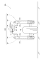
- FIG. 8 schematically shows the vehicle height adjustment device 20A of the second embodiment and corresponds to FIG.
- the vehicle height adjustment device 20A is mounted on a two-wheeled vehicle 10A (saddle-ride type vehicle 10A).
- the other basic configuration is the same as the vehicle height adjustment device 20 according to the first embodiment.
- the vehicle height adjustment device 20A according to the second embodiment can also obtain the above-described predetermined effect of the present invention.
- FIG. 9 schematically shows the vehicle height adjustment device 20B of the third embodiment, and corresponds to FIG.
- FIG. 10 is a cross-sectional view taken along line 10-10 of FIG. 9, and is shown in correspondence with FIG.
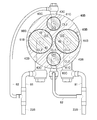
- FIG. 4 In a vehicle height adjustment device 20B according to the third embodiment, four oil chambers Oi1 to Oi4 are provided inside a cylinder 40B.
- the oil chambers Oi1 to Oi4 can be divided into two types of oil chambers depending on their sizes.
- the first oil chambers Oi1 and Oi2 are larger than the second oil chambers Oi3 and Oi4.
- the first oil chamber Oi1 or Oi2 which is the largest possible oil chamber is provided for the cylinder 40B, and the second oil chamber Oi3 or Oi4 which is the additional oil chamber is provided at the remaining portion.
- the two first oil chambers Oi1, Oi2 have the same size.
- the two second oil chambers Oi3, Oi4 have the same size.
- connection member 23B connecting the cylinder oil holes 43B and 43C to the damper oil hole 22b includes a first tube 81 through which oil from the first oil chambers Oi1 and Oi2 flows, and a second oil chamber Oi3 and Oi4. And a second tube 82 through which the oil flows.
- the first tube 81 and the second tube 82 merge.
- First piston bodies 61B and 61B are accommodated in the first oil chambers Oi1 and Oi2, respectively.
- Second piston bodies 61C and 61C are accommodated in the second oil chambers Oi3 and Oi4, respectively.
- the first piston body 61B is larger than the second piston body 61C.
- the other basic configuration is the same as the vehicle height adjustment device 20 according to the first embodiment.
- symbol, detailed description is abbreviate
- the flow rate of the oil flowing to the one connection member 23B is defined by the cross-sectional area of the first oil chamber Oi1 and the second oil chamber Oi3.
- the flow rate of the oil flowing to the other connection member 23B is defined by the cross-sectional areas of the first oil chamber Oi2 and the second oil chamber Oi4.
- the respective piston bodies 61B and 61C move by the same amount. Therefore, the flow rate of the oil flowing in each of the connection members 23B and 23B is the same.
- the movement amounts of the pistons 60B and 60C can be made the same, and the inflow amount and the outflow amount of oil can be controlled. That is, the vehicle height adjustment device 20B according to the third embodiment can also obtain the predetermined effects of the present invention.
- the dead space inside the cylinder 40B can be reduced, and the cylinder 40B can be miniaturized.
- the vehicle height adjustment device can also be applied to a two-wheeled vehicle, a three-wheeled vehicle, and a four-wheeled vehicle on which an occupant straddles. Furthermore, the present invention is also applicable to vehicles other than saddle-ride type vehicles.
- the number of damper devices provided in the vehicle height adjustment device may be two or more.
- the number of damper devices is not limited to two as described in the embodiments.
- the present invention is not limited to the examples as long as the functions and effects of the present invention can be achieved.
- the vehicle height adjustment device of the present invention is suitable for adjusting the height of a tricycle.
Landscapes
- Engineering & Computer Science (AREA)
- Mechanical Engineering (AREA)
- General Engineering & Computer Science (AREA)
- Physics & Mathematics (AREA)
- Fluid Mechanics (AREA)
- Vehicle Body Suspensions (AREA)
- Fluid-Damping Devices (AREA)
- Axle Suspensions And Sidecars For Cycles (AREA)
Abstract
L'invention concerne un dispositif de réglage de hauteur de véhicule (20) comprenant : un corps cylindrique (40) dont l'intérieur est divisé par une paroi de séparation (42) en une pluralité de chambres d'huile (Oi), des trous d'huile de corps cylindriques (43) reliés à l'extérieur étant disposés dans chacune des chambres d'huile (Oi) ; une partie d'actionnement (50), disposée sur le corps cylindrique (40) de façon à pouvoir tourner, la partie d'actionnement (50) pouvant se déplacer le long d'une ligne d'axe (CL1) en tournant ; des pistons (60) logés dans chacune des chambres d'huile (Oi) ; et une pluralité de dispositifs amortisseurs (22) pourvus de trous d'huile d'amortisseur (22b) dans lesquels s'écoule l'huile s'écoulant hors des trous d'huile de corps cylindrique (43), la hauteur du véhicule étant réglable en fonction de la quantité d'huile remplissant les trous d'huile d'amortisseur (22b).
Priority Applications (2)
| Application Number | Priority Date | Filing Date | Title |
|---|---|---|---|
| EP17919601.9A EP3659835B1 (fr) | 2017-07-28 | 2017-08-02 | Dispositif de réglage de hauteur de véhicule |
| US16/696,312 US11072219B2 (en) | 2017-07-28 | 2019-11-26 | Vehicle height adjusting apparatus |
Applications Claiming Priority (2)
| Application Number | Priority Date | Filing Date | Title |
|---|---|---|---|
| JP2017-146762 | 2017-07-28 | ||
| JP2017146762 | 2017-07-28 |
Related Child Applications (1)
| Application Number | Title | Priority Date | Filing Date |
|---|---|---|---|
| US16/696,312 Continuation US11072219B2 (en) | 2017-07-28 | 2019-11-26 | Vehicle height adjusting apparatus |
Publications (1)
| Publication Number | Publication Date |
|---|---|
| WO2019021491A1 true WO2019021491A1 (fr) | 2019-01-31 |
Family
ID=65039502
Family Applications (1)
| Application Number | Title | Priority Date | Filing Date |
|---|---|---|---|
| PCT/JP2017/027957 Ceased WO2019021491A1 (fr) | 2017-07-28 | 2017-08-02 | Dispositif de réglage de hauteur de véhicule |
Country Status (4)
| Country | Link |
|---|---|
| US (1) | US11072219B2 (fr) |
| EP (1) | EP3659835B1 (fr) |
| JP (1) | JP6476271B2 (fr) |
| WO (1) | WO2019021491A1 (fr) |
Cited By (1)
| Publication number | Priority date | Publication date | Assignee | Title |
|---|---|---|---|---|
| EP3623657A1 (fr) * | 2018-08-20 | 2020-03-18 | Harley-Davidson Motor Company Group, LLC | Ajusteur de réservoir hydraulique double |
Families Citing this family (2)
| Publication number | Priority date | Publication date | Assignee | Title |
|---|---|---|---|---|
| US12115824B2 (en) | 2022-03-28 | 2024-10-15 | Rivian Ip Holdings, Llc | Configurable interconnected suspension system |
| US12049114B2 (en) * | 2022-10-06 | 2024-07-30 | Rivian Ip Holdings, Llc | Configurable interconnected suspension system |
Citations (4)
| Publication number | Priority date | Publication date | Assignee | Title |
|---|---|---|---|---|
| JPS58118408A (ja) | 1982-01-07 | 1983-07-14 | Honda Motor Co Ltd | 油圧式車高調整装置 |
| JPS6236809U (fr) * | 1985-08-21 | 1987-03-04 | ||
| JPH0364192U (fr) * | 1989-10-27 | 1991-06-21 | ||
| JP2012131501A (ja) * | 2012-01-31 | 2012-07-12 | Carrosser Co Ltd | 車高調整式サスペンションの車高調整制御装置 |
Family Cites Families (12)
| Publication number | Priority date | Publication date | Assignee | Title |
|---|---|---|---|---|
| JPS5128891B2 (fr) * | 1973-03-12 | 1976-08-21 | ||
| US5086866A (en) | 1989-10-26 | 1992-02-11 | Suzuki Kabushiki Kaisha | Motorcycle having body height adjustor |
| GB2238990B (en) * | 1989-10-31 | 1993-10-06 | Showa Mfg | Vehicle height adjusting mechanism |
| JP3347597B2 (ja) * | 1996-08-07 | 2002-11-20 | ヤマハ発動機株式会社 | 車両用懸架装置 |
| JP3651725B2 (ja) * | 1997-01-17 | 2005-05-25 | カヤバ工業株式会社 | サスペンション装置 |
| JP4956010B2 (ja) * | 2006-02-03 | 2012-06-20 | 株式会社キャロッセ | 車高調整式サスペンションの車高調整制御装置 |
| US8801015B2 (en) * | 2012-08-31 | 2014-08-12 | Yamaha Hatsudoki Kabushiki Kaisha | Vehicle |
| JP6416515B2 (ja) * | 2014-04-03 | 2018-10-31 | 株式会社ダイゾー | 吐出容器 |
| KR101989061B1 (ko) * | 2014-06-11 | 2019-06-13 | 주식회사 만도 | 차량용 액티브 서스펜션 장치 |
| KR101971549B1 (ko) * | 2014-06-11 | 2019-04-23 | 주식회사 만도 | 차량용 액티브 서스펜션 장치 |
| JP2017136918A (ja) * | 2016-02-02 | 2017-08-10 | ヤマハ発動機株式会社 | 雪上車 |
| US11161384B2 (en) * | 2018-08-20 | 2021-11-02 | Harley-Davidson Motor Company Group, LLC | Dual hydraulic tank adjuster |
-
2017
- 2017-08-02 WO PCT/JP2017/027957 patent/WO2019021491A1/fr not_active Ceased
- 2017-08-02 EP EP17919601.9A patent/EP3659835B1/fr active Active
- 2017-12-05 JP JP2017233005A patent/JP6476271B2/ja active Active
-
2019
- 2019-11-26 US US16/696,312 patent/US11072219B2/en active Active
Patent Citations (4)
| Publication number | Priority date | Publication date | Assignee | Title |
|---|---|---|---|---|
| JPS58118408A (ja) | 1982-01-07 | 1983-07-14 | Honda Motor Co Ltd | 油圧式車高調整装置 |
| JPS6236809U (fr) * | 1985-08-21 | 1987-03-04 | ||
| JPH0364192U (fr) * | 1989-10-27 | 1991-06-21 | ||
| JP2012131501A (ja) * | 2012-01-31 | 2012-07-12 | Carrosser Co Ltd | 車高調整式サスペンションの車高調整制御装置 |
Non-Patent Citations (1)
| Title |
|---|
| See also references of EP3659835A4 |
Cited By (2)
| Publication number | Priority date | Publication date | Assignee | Title |
|---|---|---|---|---|
| EP3623657A1 (fr) * | 2018-08-20 | 2020-03-18 | Harley-Davidson Motor Company Group, LLC | Ajusteur de réservoir hydraulique double |
| US11161384B2 (en) * | 2018-08-20 | 2021-11-02 | Harley-Davidson Motor Company Group, LLC | Dual hydraulic tank adjuster |
Also Published As
| Publication number | Publication date |
|---|---|
| EP3659835A4 (fr) | 2021-04-28 |
| US20200094646A1 (en) | 2020-03-26 |
| JP6476271B2 (ja) | 2019-02-27 |
| US11072219B2 (en) | 2021-07-27 |
| JP2019026238A (ja) | 2019-02-21 |
| EP3659835B1 (fr) | 2024-06-12 |
| EP3659835A1 (fr) | 2020-06-03 |
Similar Documents
| Publication | Publication Date | Title |
|---|---|---|
| US12038062B2 (en) | Method and apparatus for an adjustable damper | |
| US11859690B2 (en) | Suspension system | |
| EP3932789A2 (fr) | Ensemble de montant de siège à réglage pneumatique uniquement en hauteur | |
| US8622180B2 (en) | Methods and apparatus for variable damping adjuster | |
| US20170274959A1 (en) | Air spring structure | |
| JP5466558B2 (ja) | アジャスタ装置、アジャスタ装置を備える緩衝器 | |
| US20060237272A1 (en) | Shock absorber | |
| US9688345B2 (en) | Suspension device | |
| JP6476271B2 (ja) | 車高調整装置 | |
| JPH06270875A (ja) | 自転車用車輪懸架装置 | |
| US9267568B2 (en) | Shock absorber | |
| TWI816079B (zh) | 自行車懸吊組件 | |
| US20060131118A1 (en) | Oil shock absorber | |
| NL2025340A (en) | Single front fork shock absorber of bicycle | |
| JP5909407B2 (ja) | 緩衝装置 | |
| KR101474861B1 (ko) | 완충기 | |
| JP2008240839A (ja) | 油圧緩衝器 | |
| TWI571395B (zh) | The suspension of the wheel | |
| JP2011122623A (ja) | 調節装置 | |
| JP2006022947A (ja) | 自動二輪車等のフロントフォーク | |
| JP2007092937A (ja) | 油圧緩衝器のばね荷重調整装置 | |
| JP2021173385A (ja) | 油圧緩衝器 | |
| JP2006329220A (ja) | ダンパ |
Legal Events
| Date | Code | Title | Description |
|---|---|---|---|
| 121 | Ep: the epo has been informed by wipo that ep was designated in this application |
Ref document number: 17919601 Country of ref document: EP Kind code of ref document: A1 |
|
| NENP | Non-entry into the national phase |
Ref country code: DE |
|
| WWE | Wipo information: entry into national phase |
Ref document number: 2017919601 Country of ref document: EP |