WO2019021661A1 - 充電システム、充電装置、および電気治療器の制御装置 - Google Patents
充電システム、充電装置、および電気治療器の制御装置 Download PDFInfo
- Publication number
- WO2019021661A1 WO2019021661A1 PCT/JP2018/022372 JP2018022372W WO2019021661A1 WO 2019021661 A1 WO2019021661 A1 WO 2019021661A1 JP 2018022372 W JP2018022372 W JP 2018022372W WO 2019021661 A1 WO2019021661 A1 WO 2019021661A1
- Authority
- WO
- WIPO (PCT)
- Prior art keywords
- control device
- power
- unit
- charging
- light
- Prior art date
- Legal status (The legal status is an assumption and is not a legal conclusion. Google has not performed a legal analysis and makes no representation as to the accuracy of the status listed.)
- Ceased
Links
Images






Classifications
-
- H—ELECTRICITY
- H02—GENERATION; CONVERSION OR DISTRIBUTION OF ELECTRIC POWER
- H02J—ELECTRIC POWER NETWORKS; CIRCUIT ARRANGEMENTS OR SYSTEMS FOR SUPPLYING OR DISTRIBUTING ELECTRIC POWER; SYSTEMS FOR STORING ELECTRIC ENERGY
- H02J50/00—Circuit arrangements or systems for wireless supply or distribution of electric power
- H02J50/10—Circuit arrangements or systems for wireless supply or distribution of electric power using inductive coupling
-
- A—HUMAN NECESSITIES
- A61—MEDICAL OR VETERINARY SCIENCE; HYGIENE
- A61N—ELECTROTHERAPY; MAGNETOTHERAPY; RADIATION THERAPY; ULTRASOUND THERAPY
- A61N1/00—Electrotherapy; Circuits therefor
- A61N1/02—Details
- A61N1/08—Arrangements or circuits for monitoring, protecting, controlling or indicating
-
- A—HUMAN NECESSITIES
- A61—MEDICAL OR VETERINARY SCIENCE; HYGIENE
- A61N—ELECTROTHERAPY; MAGNETOTHERAPY; RADIATION THERAPY; ULTRASOUND THERAPY
- A61N1/00—Electrotherapy; Circuits therefor
- A61N1/18—Applying electric currents by contact electrodes
- A61N1/32—Applying electric currents by contact electrodes alternating or intermittent currents
- A61N1/36—Applying electric currents by contact electrodes alternating or intermittent currents for stimulation
- A61N1/36014—External stimulators, e.g. with patch electrodes
-
- H—ELECTRICITY
- H02—GENERATION; CONVERSION OR DISTRIBUTION OF ELECTRIC POWER
- H02J—ELECTRIC POWER NETWORKS; CIRCUIT ARRANGEMENTS OR SYSTEMS FOR SUPPLYING OR DISTRIBUTING ELECTRIC POWER; SYSTEMS FOR STORING ELECTRIC ENERGY
- H02J50/00—Circuit arrangements or systems for wireless supply or distribution of electric power
- H02J50/80—Circuit arrangements or systems for wireless supply or distribution of electric power involving the exchange of data, concerning supply or distribution of electric power, between transmitting devices and receiving devices
-
- H—ELECTRICITY
- H02—GENERATION; CONVERSION OR DISTRIBUTION OF ELECTRIC POWER
- H02J—ELECTRIC POWER NETWORKS; CIRCUIT ARRANGEMENTS OR SYSTEMS FOR SUPPLYING OR DISTRIBUTING ELECTRIC POWER; SYSTEMS FOR STORING ELECTRIC ENERGY
- H02J7/00—Circuit arrangements for charging or discharging batteries or for supplying loads from batteries
- H02J7/02—Circuit arrangements for charging or discharging batteries or for supplying loads from batteries for charging batteries from AC mains by converters
-
- H—ELECTRICITY
- H02—GENERATION; CONVERSION OR DISTRIBUTION OF ELECTRIC POWER
- H02J—ELECTRIC POWER NETWORKS; CIRCUIT ARRANGEMENTS OR SYSTEMS FOR SUPPLYING OR DISTRIBUTING ELECTRIC POWER; SYSTEMS FOR STORING ELECTRIC ENERGY
- H02J7/00—Circuit arrangements for charging or discharging batteries or for supplying loads from batteries
- H02J7/40—Circuit arrangements for charging or discharging batteries or for supplying loads from batteries characterised by the exchange of charge or discharge related data
- H02J7/47—Arrangements for checking compatibility or authentication between one component, e.g. a battery or a battery charger, and another component, e.g. a power source
-
- H—ELECTRICITY
- H02—GENERATION; CONVERSION OR DISTRIBUTION OF ELECTRIC POWER
- H02J—ELECTRIC POWER NETWORKS; CIRCUIT ARRANGEMENTS OR SYSTEMS FOR SUPPLYING OR DISTRIBUTING ELECTRIC POWER; SYSTEMS FOR STORING ELECTRIC ENERGY
- H02J7/00—Circuit arrangements for charging or discharging batteries or for supplying loads from batteries
- H02J7/80—Circuit arrangements for charging or discharging batteries or for supplying loads from batteries including monitoring or indicating arrangements
-
- H—ELECTRICITY
- H02—GENERATION; CONVERSION OR DISTRIBUTION OF ELECTRIC POWER
- H02J—ELECTRIC POWER NETWORKS; CIRCUIT ARRANGEMENTS OR SYSTEMS FOR SUPPLYING OR DISTRIBUTING ELECTRIC POWER; SYSTEMS FOR STORING ELECTRIC ENERGY
- H02J2105/00—Networks for supplying or distributing electric power characterised by their spatial reach or by the load
- H02J2105/40—Networks for supplying or distributing electric power characterised by their spatial reach or by the load characterised by the loads connecting to the networks or being supplied by the networks
- H02J2105/46—Medical devices, medical implants or life supporting devices
Definitions
- the present disclosure relates to a technology for contactlessly charging a control device of an electrotherapy device.
- Patent Document 1 discloses a method and apparatus for wirelessly charging portable electronic devices such as portable devices.
- an electric therapy device for example, a low frequency treatment device which performs treatment such as loosening of the shoulder is constituted by a control device which controls various processes as a main body portion, a removable pad and the like.
- the control device is equipped with a secondary battery as a power source, and is relatively small in size. There is a need to charge the secondary battery contactlessly in order to improve the complexity of the charging operation. In addition, there is also a growing demand to make it impossible for the control device to be artificially charged.
- An object of the present disclosure is, in one aspect, to provide a charging system capable of charging a control device of an electrotherapy device held by a charging device in a simple and appropriate contactless manner.
- the present disclosure aims to provide a charging device used in such a charging system, and a control device of an electrotherapy device.
- a charging system includes a control device of an electrotherapy device and a charging device that charges the control device contactlessly.
- the charging device includes a support portion and a recessed holding portion formed on the support portion for fitting the control device.
- the control device includes a light emitting unit that emits light when the control device is fitted into the holding unit.
- the charging device includes a light receiving unit that receives light from the light emitting unit, an authentication unit that executes an authentication process that compares and collates first information based on the received light with predetermined second information, and power. It further includes a power transmission coil for power transmission, and a power transmission control unit that transmits power from the power transmission coil when authentication by the authentication unit is successful.
- the control device further includes a power receiving coil that receives power from the power transmitting coil, and a secondary battery that is charged by the power received by the power receiving coil.
- the holding portion includes a flat portion corresponding to the shape of the bottom surface of the control device and a curved surface portion corresponding to the curved shape formed on the outer edge of the bottom surface of the control device.
- the bottom surface of the control device is provided with a positioning recess
- the flat portion of the holding portion is provided with a positioning protrusion fitted to the positioning recess.
- the light emitting unit emits light at a predetermined interval.
- the authentication unit executes an authentication process each time light is received by the light receiving unit.
- the power transmission control unit stops power transmission of power from the power transmission coil when authentication by the authentication unit fails while power is being transmitted from the power transmission coil.
- the light emitting unit stops light emission when charging of the secondary battery is completed.
- the electrotherapy device is a low frequency therapy device.
- a charging device for contactlessly charging a control device of an electrotherapy device.
- the charging device receives the light emitted from the control device when the control device is fitted into the support portion, the concave holding portion formed on the support portion for fitting the control device, and the holding portion.
- An authentication unit that executes an authentication process that compares the first information based on the received light with a predetermined second information, a power transmission coil for transmitting electric power, and the authentication unit
- a power transmission control unit configured to transmit power from the power transmission coil to the power receiving coil included in the control device when the authentication is successful.
- a control device of an electrotherapy device which is contactlessly charged by the power from the charging device.
- the control device is a light emitting unit that emits light when the control device is fitted into the concave holding unit formed in the support unit of the charging device, and a first based on the light received by the light receiving unit of the charging device.
- a power receiving coil for receiving power transmitted from the power transmission coil of the charging device when authentication processing for comparing and collating the information and the predetermined second information is successful; and 2 for charging by the power received by the power receiving coil And a secondary battery.
- the charging system according to this embodiment WHEREIN: It is a perspective view which shows the state which isolate
- FIG. 2 is a block diagram showing functional configurations of a control device and a charging device according to the present embodiment. It is a flow chart which shows an example of a processing procedure of a control device and a charging device according to this embodiment.
- FIG. 1 is a perspective view showing a state in which a control device and a charging device are separated in the charging system according to the present embodiment.
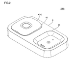
- FIG. 2 is a perspective view showing a state where the control device is set to the charging device in the charging system according to the present embodiment.
- charging system 1000 includes a control device 4 (housing 4 a) which is a main portion of an electrotherapy device, and a charging device 6 for charging control device 4.
- the electrotherapy device according to the present embodiment is a so-called cordless type low frequency therapy device.
- the control device 4 is equipped with a rechargeable secondary battery.
- the control device 4 (the housing 4 a) is fitted into and held by the concave holding portion 62 of the charging device 6.
- the lower member of the housing 4a and the holding portion 62 of the charging device 6 are fitted, and the housing 4a and the charging device 6 are held in close contact with each other.
- Non-contact charging is performed by mounting a coil on each of the charging device 6 on the power transmission side and the control device 4 on the power receiving side, and non-contactly transmitting power by electromagnetic induction between the coils.
- a member for example, a metal terminal
- the control device 4 can be easily held by the charging device 6, and short circuit due to mixing of dust, moisture, and the like in the member can be prevented.
- FIG. 3 is a plan view showing the pad and the holder of the electric therapeutic device according to the present embodiment.
- FIG. 4 is a perspective view showing a control device of the electrotherapy device according to the present embodiment.
- FIG. 5 is a plan view of a control device of the electrotherapy device according to the present embodiment.
- FIG. 6 is a side view seen from the arrow VI in FIG.
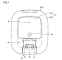
- FIG. 7 is a bottom view of the control device of the electrotherapy device according to the present embodiment.
- the electrotherapy device includes the pad 2 and the holder 3 shown in FIG. 3 and the control device 4 which is the main body shown in FIGS. 4 to 7.
- pad 2 has a sheet-like shape and is attached to the user's body.
- a conductive layer 2 a is provided on the surface (lower surface) of the body side 21 facing the body among the outer surfaces of the pad 2.
- the pad 2 is attached on the skin of the user using a conductive gel or the like, and a low frequency pulse current is supplied to the user through the conductive layer 2a.
- the pad 2 is held by the holder 3.
- a through hole 23 is provided in the pad 2, and the protruding terminal 33 of the holder 3 is inserted into the through hole 23.
- the treatment part 2Y of the pad 2 is provided on the left and right sides, and the conductive layer 2a is exposed on the body side 21 of the treatment part 2Y.
- the protruding terminals 33 of the holder 3 are formed for electrical connection with the terminal holes 43 (see FIG. 7) on the control device 4 side.
- a pulse current is supplied to the user through the conductive layer 2 a of the pad 2.
- the pad 2 is a consumable item, the pad 2 is removable from the control device 4 at the time of replacement.
- the holder 3 is integrated by holding the pad 2, and the control device 4 is attached to and detached from the pad 2 and the holder 3. Although the pad 2 is replaced with the holder 3, it is not impossible to reuse the holder 3 as needed.
- control device 4 includes, as an exterior body, a casing 4a having a substantially rectangular parallelepiped shape.
- the control device 4 (the housing 4 a) is detachably attached to the holder 3.
- the control device 4 supplies a low frequency pulse current to the conductive layer 2 a of the pad 2 in a state of being attached to the holder 3.
- the housing 4a is composed of an upper member 111 including an upper surface portion 110 and a side surface portion 112, and a lower member 114, as shown in FIGS.
- the upper member 111 and the lower member 114 are connected.
- the upper surface portion 110 has a substantially rectangular shape slightly curved toward the outside of the housing 4a.
- a power button 45 is integrally provided on the upper surface portion 110.
- the side surface portion 112 has a substantially annular shape.
- the side surface portion 112 is provided with a button 46 for attaching and detaching the holder 3 to and from the housing 4a.
- the lower member 114 is composed of a substantially rectangular flat bottom portion 114 a and a curved surface portion 114 b formed in a convex curved surface from the edge of the bottom portion 114 a.
- the curved surface portion 114 b together with the upper surface portion 110 and the side surface portion 112 realizes a three-dimensional shape of the control device 4.
- a substrate, an electric circuit, a secondary battery, a power receiving coil 54, and the like are provided in the control device 4 (the housing 4a).
- An electrical circuit is mounted on the surface of the substrate.
- the electric circuit includes a processor for executing various processes, a memory for storing programs and data, a communication interface for wirelessly communicating various data with an external device, boosting of power supply voltage, and low frequency pulse current (treatment current Waveform generation and output device for generating and outputting etc.).
- the control device 4 can charge the secondary battery using the power received by the power receiving coil 54.
- the bottom surface portion 114 a is provided with a positioning recess 52 for positioning the control device 4 with respect to the holding portion 62 of the charging device 6.
- the positioning recess 52 is fitted into the positioning protrusion provided in the holding portion 62, whereby the control device 4 is held by the holding portion 62.
- a terminal hole 43 for inserting the protruding terminal 33 of the holder 3 is provided inside the positioning recess 52.
- the terminal holes 43 are electrically connected to a substrate (electric circuit) inside the housing 4a.
- an LED 48 as a light emitting portion and a reset button 49 are provided in the bottom portion 114a.
- the LED 48 emits light in accordance with the instruction of the processor of the control device 4.
- the reset button 49 is a button for initializing the electrotherapy device 20. For example, when the electrotherapy device 20 receives pressing of the reset button 49, the electrotherapy device 20 deletes the pairing information and the like stored in the internal memory when being paired with the external device.
- FIG. 8 is a perspective view showing charging device 6 according to the present embodiment.
- FIG. 9 is a plan view of charging device 6 according to the present embodiment.
- the charging device 6 holds the control device 4 and charges the secondary battery accommodated in the control device 4.
- charging device 6 includes a support portion 61 and two holding portions 62 formed on the surface of support portion 61.
- the support portion 61 is a base that supports the control device 4 (the housing 4 a) held by the holding portion 62, and the holding portion 62 is formed on the substantially rectangular upper surface side.
- the two holding portions 62 are formed in the support portion 61, the two control devices 4 can be charged simultaneously by fitting the control devices 4 into the respective holding portions 62. it can.
- the number of holding portions 62 provided in the support portion 61 may be one.
- the holding portion 62 shows a portion for holding the control device 4, and is formed so as to be recessed in a shape corresponding to the shape of the lower member 114 of the housing 4 a. Specifically, the holding portion 62 has a concave shape for fitting the lower member 114. Further, as shown in FIG. 9, the shape of the outer edge of the holding portion 62 as viewed from the front is formed in a substantially rectangular shape.
- the holding portion 62 is composed of a flat portion 68 and a curved portion 66.
- the flat portion 68 faces the bottom surface portion 114 a of the lower member 114 held by the holding portion 62.
- the curved surface portion 66 is a concave curved surface and faces the curved surface portion 114 b of the lower member 114 held by the holding portion 62. That is, the holding portion 62 has a flat portion 68 corresponding to the shape of the bottom surface portion 114 a of the control device 4 and a curved surface portion 66 corresponding to the curved surface portion 114 b formed at the outer edge of the bottom surface portion 114 a.
- the flat portion 68 of the holding portion 62 is provided with a positioning convex portion 64 fitted to the positioning concave portion 52 of the control device 4 (the housing 4 a).
- the housing 4 a is held by the inner peripheral edge of the positioning recess 52 being fitted into the positioning protrusion 64.
- the light receiving element 70 is a light detector such as a photodiode.
- the light receiving element 70 is provided to face the LED 48 provided on the lower member 114 of the housing 4 a in a state where the control device 4 is held by the holding unit 62.
- a power transmission coil 72 for transmitting power to the power reception coil 54, a power supply connection terminal connected to an external power supply, and the like are provided inside the support portion 61 of the charging device 6, a power transmission coil 72 for transmitting power to the power reception coil 54, a power supply connection terminal connected to an external power supply, and the like are provided.
- the power transmission coil 72 is provided to face the power receiving coil 54 of the control device 4 in a state where the control device 4 (the housing 4 a) is held by the holding unit 62.
- a current flows through the transmission coil 72 to generate a magnetic field. Power can be generated in the receiving coil 54 of the control device 4 by the flow of the magnetic force.
- the electric circuit includes a processor, a memory, and the like that receives various electric signals received by the light receiving element 70 and performs various processes.
- FIG. 10 is a block diagram showing an example of a hardware configuration of a control device of the electrotherapy device according to the present embodiment.
- control device 4 includes, as main components, processor 210, memory 220, input interface (I / F) 230, secondary battery 240, charging circuit 250, and waveform generation and output device. 260, a receiving coil 54, and an LED 48.
- the processor 210 is typically an arithmetic processing unit such as a central processing unit (CPU) or a multi processing unit (MPU).
- the processor 210 functions as a control unit that controls the operation of each unit of the control device 4 by reading and executing the program stored in the memory 220.
- the processor 210 implements each of the processes (steps) of the control device 4 described later by executing the program.
- the memory 220 is realized by a random access memory (RAM), a read-only memory (ROM), or the like.
- the memory 220 stores programs executed by the processor 210, data used by the processor 210, and the like.
- the input interface 230 is various buttons for receiving an instruction from the user.
- the secondary battery 240 supplies power to each component of the control device 4.
- the secondary battery 240 is, for example, a lithium ion battery.
- the charging circuit 250 is connected to the power receiving coil 54 for charging, and uses the power derived from the power receiving coil 54 to charge the secondary battery 240.
- the waveform generation output device 260 outputs a current flowing through the pad 2 to a treatment site on the user's body.
- the waveform generation and output device 260 includes a booster circuit, a voltage adjustment circuit, an output circuit, a current detection circuit, and the like.
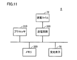
- FIG. 11 is a block diagram showing an example of a hardware configuration of the charging device according to the present embodiment.
- charging device 6 includes, as main components, processor 310 for executing various processes, memory 320 for storing various information, power transmission circuit 330, power transmission coil 72, and light receiving element 70. And.
- the light receiving element 70 converts the received light into an electrical signal, and inputs the electrical signal to the processor 310.
- the processor 310 controls the power transmission circuit 330 based on the electrical signal converted by the light receiving element 70.
- the power transmission circuit 330 supplies the AC power received from an external power source such as a household power source to the power transmission coil 72 according to the instruction of the processor 310.
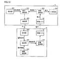
- FIG. 12 is a block diagram showing functional configurations of control device 4 and charging device 6 according to the present embodiment.
- control device 4 includes, as main functional components, detection unit 402, light emission control unit 404, light emission unit 406, and charge control unit 408.
- Charging device 6 includes, as main functional components, light receiving unit 450, authentication unit 452, information storage unit 454, and power transmission control unit 456.
- the detection unit 402 of the control device 4 detects the holding state of the control device 4 with respect to the holding unit 62 of the charging device 6. Specifically, in the detection unit 402, whether the positioning concave portion 52 of the control device 4 is fitted into the positioning convex portion 64 provided in the holding portion 62 of the charging device 6 (that is, the control device 4 is held To detect whether or not they are not fitted (that is, the state in which the control device 4 is not held).
- the detection unit 402 may mechanically detect that the positioning protrusion 64 has been fitted into the positioning recess 52 via a switch (not shown) provided in the positioning recess 52. Further, the detection unit 402 indicates that the positioning convex portion 64 is fitted into the positioning concave portion 52 based on a voltage change when the positioning convex portion 64 contacts a terminal (not shown) provided in the positioning concave portion 52. It may be detected.
- Information on the detection result of the detection unit 402 (for example, information indicating that the control device 4 is held in the holding unit 62) is supplied to the light emission control unit 404.
- the light emission control unit 404 causes the light emitting unit 406 to emit light when the control device 4 is fitted into the holding unit 62.
- the light from the light emitting unit 406 is used for the authentication process of the charging device 6. Specifically, when the control device 4 is fitted in the holding unit 62, the light emission control unit 404 causes the light emitting unit 406 to emit light at predetermined intervals (for example, every one second).
- the light emission control unit 404 stops the light emission from the light emitting unit 406 when the holding of the control device 4 to the holding unit 62 is released.
- the light emission control unit 404 is realized by the processor 210, for example.
- the light emitting unit 406 is realized by, for example, the LED 48.
- the light receiving unit 450 of the charging device 6 receives the light from the light emitting unit 406, converts the light into an electrical signal, and supplies the electrical signal to the authenticating unit 452.
- the light receiving unit 450 is realized by, for example, the light receiving element 70.
- the authentication unit 452 authenticates whether the light received by the light receiving unit 450 permits the power transmission to the control device 4. Specifically, the authentication unit 452 executes an authentication process of comparing and collating information based on the received light with predetermined reference information.
- the reference information is information indicating the definition of light indicating permission of power transmission, and is stored in the information storage unit 454 implemented by the memory 320.
- the reference information is information on light emitted by the LED 48 of the control device 4.
- Information on light may be information indicating wavelength characteristics of light, or information indicating transmission intensity of a specific wavelength.
- the authentication unit 452 compares the wavelength characteristic of the received light with the wavelength characteristic indicated by the reference information, and determines that the authentication is successful if they match.
- the authentication unit 452 compares the transmission intensity of the specific wavelength of the received light with the transmission intensity of the specific wavelength indicated by the reference information, and determines that the authentication is successful if they match. That is, when it is confirmed that the received light is the light emitted from the LED 48 mounted on the control device 4, the authentication unit 452 determines that the authentication is successful.
- the authentication unit 452 executes an authentication process each time light is received by the light receiving unit 450 (that is, each time light is emitted from the light emitting unit 406 at a predetermined interval).
- the authentication result of the authentication unit 452 is supplied to the power transmission control unit 456.
- the authentication unit 452 is realized by, for example, the processor 310.
- the power transmission control unit 456 causes the power transmission coil 72 to transmit power.
- the power transmission control unit 456 stops the power transmission of the power from the power transmission coil 72 when the authentication by the authentication unit 452 fails while the power is transmitted from the power transmission coil 72.
- the power transmission control unit 456 is realized by, for example, the processor 310 and the power transmission circuit 330.
- the charge control unit 408 of the control device 4 receives the power from the power transmission coil 72 via the power reception coil 54, and supplies the power to the secondary battery 240.
- the charge control unit 408 is configured to be able to detect the remaining amount of the secondary battery 240. Since the output voltage or output current of the secondary battery decreases in accordance with the remaining battery charge, the charge control unit 408 detects the remaining battery charge based on the output voltage or output current.
- the charge control unit 408 supplies information indicating the completion of charging to the light emission control unit 404 when the charging of the secondary battery 240 is completed (that is, when the battery remaining amount is 100% and the battery is fully charged). Do. When the charging of the secondary battery 240 is completed, the light emission control unit 404 stops the emission of light by the light emitting unit 406.
- FIG. 13 is a flowchart showing an example of the processing procedure of the control device and the charging device according to the present embodiment. For example, each step of the following control device 4 is performed by the processor 210, and each step of the charging device 6 is performed by the processor 310. The following processing is repeated at predetermined intervals (control cycles).
- control device 4 determines whether or not housing 4 a is held by holding unit 62 of charging device 6 (step S ⁇ b> 10). Specifically, the control device 4 determines whether the positioning recess 52 is fitted into the positioning protrusion 64 or not.
- control device 4 determines whether or not secondary battery 240 is in a fully charged state (that is, a charging completed state) (step S12). If the secondary battery 240 is not fully charged (NO in step S12), the control device 4 causes the LED 48 to emit light (step S14).
- control device 4 ends the process.
- the LED 48 does not emit light.
- control device 4 ends the process. Also in this case, the LED 48 does not emit light. That is, even when the case 4a is held by the holding portion 62, the control device 4 does not emit light from the LED 48 when the secondary battery 240 is fully charged (the light from the LED 48 Stop the light emission).
- the charging device 6 determines whether light is received through the light receiving element 70 (step S16). If the charging device 6 does not receive light (NO in step S16), the charging device 6 executes the process of step S24, which is vertical. On the other hand, when the charging device 6 receives the light (YES in step S16), the charging device 6 determines whether the authentication process has succeeded based on the received light (step S18). Specifically, the charging device 6 performs an authentication process for permitting power transmission to the control device 4 by comparing and collating information based on the received light with reference information, and performs the determination.
- step S18 If the authentication is successful (YES in step S18), the charging device 6 transmits power from the power transmission coil 72 (step S20). At this time, when power is being transmitted from the power transmission coil 72, the power transmission is maintained. The control device 4 receives power via the power receiving coil 54 (step S22), and ends the process.
- step S24 determines whether power transmission from the power transmission coil 72 is being performed. If power transmission is being performed (YES in step S24), the charging device 6 stops power transmission from the power transmission coil 72 (step S26), and ends the process. On the other hand, when power transmission is not being performed (NO in step S24), charging device 6 ends the process. In this case, the power transmission coil 72 does not start power transmission.
- ⁇ Advantage> when the control device 4 is held by the holding portion 62, extraneous external light reaching the light receiving element 70 is blocked, and the LED 48 and the light receiving element 70 are disposed at a position facing each other. Ru. Since the detection sensitivity of the light from the LED 48 is improved by the light receiving element 70, highly accurate authentication processing can be performed.
- the charging is automatically started only by the operation of fitting the control device 4 into the holding portion 62, so the convenience for the user is improved.
- the authentication process is performed at predetermined intervals, and power transmission is stopped when the authentication fails.
- security is also improved by performing authentication constantly.
- the controller 4 of the electrotherapy device may be configured not to communicate with an external device or the like when being held by the holder 62 of the charging device 6. It may be configured not to output the treatment current.
- the arrangement of the LED 48 and the light receiving element 70 is not limited to the above, and the light receiving element 70 and the LED 48 are arranged to face each other when the control device 4 is held by the holding unit 62. It should just be.
- a program that causes a computer to function to execute control as described in the above-described flowchart.
- a program is recorded on a non-temporary computer readable recording medium such as a flexible disk attached to a computer, a CD (Compact Disk Read Only Memory), a secondary storage device, a main storage device, and a memory card. It can also be provided as a program product.
- the program can be provided by being recorded in a recording medium such as a hard disk built in the computer.
- the program can be provided by downloading via a network.
- the program may call a required module among program modules provided as a part of an operating system (OS) of a computer in a predetermined arrangement at a predetermined timing to execute processing.
- OS operating system
- the program itself does not include the above module, and the processing is executed in cooperation with the OS.
- a program that does not include such a module may also be included in the program according to the present embodiment.
- the program according to the present embodiment may be provided by being incorporated into a part of another program. Also in this case, the program itself does not include a module included in the other program, and the process is executed in cooperation with the other program. Programs incorporated into such other programs may also be included in the program according to the present embodiment.
- the configuration exemplified as the above-described embodiment is an example of the configuration of the present invention, and can be combined with another known technique, and a part of the configuration can be made without departing from the scope of the present invention. It is also possible to change and configure, such as omitting. Moreover, in the embodiment described above, the processing and configuration described in the other embodiments may be appropriately adopted and implemented.
Landscapes
- Engineering & Computer Science (AREA)
- Health & Medical Sciences (AREA)
- Power Engineering (AREA)
- Life Sciences & Earth Sciences (AREA)
- Computer Networks & Wireless Communication (AREA)
- Nuclear Medicine, Radiotherapy & Molecular Imaging (AREA)
- Heart & Thoracic Surgery (AREA)
- Biomedical Technology (AREA)
- Radiology & Medical Imaging (AREA)
- Animal Behavior & Ethology (AREA)
- General Health & Medical Sciences (AREA)
- Public Health (AREA)
- Veterinary Medicine (AREA)
- Biophysics (AREA)
- Neurology (AREA)
- Charge And Discharge Circuits For Batteries Or The Like (AREA)
- Electrotherapy Devices (AREA)
Priority Applications (3)
| Application Number | Priority Date | Filing Date | Title |
|---|---|---|---|
| CN201880043941.XA CN110809847A (zh) | 2017-07-28 | 2018-06-12 | 充电系统、充电装置及电疗仪的控制装置 |
| DE112018003096.2T DE112018003096T5 (de) | 2017-07-28 | 2018-06-12 | Ladesystem, ladevorrichtung und steuervorrichtung von elektrischen behandlungsvorrichtungen |
| US16/736,388 US20200144862A1 (en) | 2017-07-28 | 2020-01-07 | Charging system, charging device, and control device of electrical treatment device |
Applications Claiming Priority (2)
| Application Number | Priority Date | Filing Date | Title |
|---|---|---|---|
| JP2017146588A JP2019030105A (ja) | 2017-07-28 | 2017-07-28 | 充電システム、充電装置、および電気治療器の制御装置 |
| JP2017-146588 | 2017-07-28 |
Related Child Applications (1)
| Application Number | Title | Priority Date | Filing Date |
|---|---|---|---|
| US16/736,388 Continuation US20200144862A1 (en) | 2017-07-28 | 2020-01-07 | Charging system, charging device, and control device of electrical treatment device |
Publications (1)
| Publication Number | Publication Date |
|---|---|
| WO2019021661A1 true WO2019021661A1 (ja) | 2019-01-31 |
Family
ID=65040462
Family Applications (1)
| Application Number | Title | Priority Date | Filing Date |
|---|---|---|---|
| PCT/JP2018/022372 Ceased WO2019021661A1 (ja) | 2017-07-28 | 2018-06-12 | 充電システム、充電装置、および電気治療器の制御装置 |
Country Status (5)
| Country | Link |
|---|---|
| US (1) | US20200144862A1 (2) |
| JP (1) | JP2019030105A (2) |
| CN (1) | CN110809847A (2) |
| DE (1) | DE112018003096T5 (2) |
| WO (1) | WO2019021661A1 (2) |
Cited By (1)
| Publication number | Priority date | Publication date | Assignee | Title |
|---|---|---|---|---|
| CN115023261A (zh) * | 2019-12-04 | 2022-09-06 | 高道Iphc公司 | 无线电刺激系统 |
Families Citing this family (11)
| Publication number | Priority date | Publication date | Assignee | Title |
|---|---|---|---|---|
| USD915610S1 (en) * | 2019-05-09 | 2021-04-06 | Rpw Technology, Llc | Wearable stimulation device |
| US11881719B2 (en) | 2019-09-12 | 2024-01-23 | Spark Connected LLC | Wireless power transfer object detection circuit and method |
| USD908621S1 (en) | 2020-06-24 | 2021-01-26 | Apple Inc. | Charger |
| USD991167S1 (en) * | 2021-04-05 | 2023-07-04 | Sariana Llc | Foldable charger |
| USD975013S1 (en) * | 2022-03-21 | 2023-01-10 | Shenzhen Niluoer Electronic Technology Co., Ltd. | Wireless charging station |
| USD1030660S1 (en) * | 2022-04-22 | 2024-06-11 | Shenzhen Yifeng Intelligent Technology Co., Ltd. | Wireless charger |
| USD1030659S1 (en) * | 2022-04-22 | 2024-06-11 | Shenzhen Yifeng Intelligent Technology Co., Ltd. | Wireless charger |
| USD993174S1 (en) * | 2022-12-02 | 2023-07-25 | Chuan Yin | Wireless charger |
| USD1024952S1 (en) * | 2023-05-09 | 2024-04-30 | Bin Yao | Wireless charging station |
| USD999735S1 (en) * | 2023-05-10 | 2023-09-26 | Bo Yan | Wireless charger |
| USD1123830S1 (en) * | 2024-02-14 | 2026-04-28 | T-Mobile Innovations Llc | Foldable electronic device charging base |
Citations (4)
| Publication number | Priority date | Publication date | Assignee | Title |
|---|---|---|---|---|
| JPH01221174A (ja) * | 1988-08-29 | 1989-09-04 | Advance Co Ltd | 小型電気刺激装置 |
| JPH04297278A (ja) * | 1991-03-26 | 1992-10-21 | Matsushita Electric Works Ltd | 血行促進装置 |
| JP2008178234A (ja) * | 2007-01-19 | 2008-07-31 | Toko Inc | 非接触電力伝送装置 |
| JP2012139011A (ja) * | 2010-12-27 | 2012-07-19 | Contec Co Ltd | 非接触給電設備の2次側受電回路 |
Family Cites Families (16)
| Publication number | Priority date | Publication date | Assignee | Title |
|---|---|---|---|---|
| JPH0467732A (ja) * | 1990-07-06 | 1992-03-03 | Seiko Instr Inc | 無線充電システム |
| JPH04317527A (ja) * | 1991-04-15 | 1992-11-09 | Matsushita Electric Works Ltd | 充電式電気器具の非接触充電装置 |
| JPH11178232A (ja) * | 1997-12-16 | 1999-07-02 | Canon Inc | 非接触充電式電子機器 |
| JP2003018757A (ja) * | 2001-06-29 | 2003-01-17 | Toko Inc | 無接点型充電装置 |
| JP2003264934A (ja) * | 2002-03-08 | 2003-09-19 | Denso Wave Inc | 非接触式充電システム、充電装置及び被充電機器 |
| US8169185B2 (en) * | 2006-01-31 | 2012-05-01 | Mojo Mobility, Inc. | System and method for inductive charging of portable devices |
| JP4743173B2 (ja) * | 2007-06-29 | 2011-08-10 | セイコーエプソン株式会社 | 送電制御装置、送電装置、無接点電力伝送システムおよび電子機器 |
| JP5556002B2 (ja) * | 2008-01-09 | 2014-07-23 | セイコーエプソン株式会社 | 送電制御装置、送電装置、無接点電力伝送システムおよび電子機器 |
| JP5544705B2 (ja) * | 2008-01-09 | 2014-07-09 | セイコーエプソン株式会社 | 送電制御装置、送電装置、無接点電力伝送システム、電子機器および送電制御方法 |
| CN101640439A (zh) * | 2008-07-16 | 2010-02-03 | 精工爱普生株式会社 | 输电/受电控制装置、输电/受电装置、电子设备及无接点电力传输方法 |
| JP2010200511A (ja) * | 2009-02-26 | 2010-09-09 | Panasonic Corp | 充電器、電子機器、及び電子機器充電システム |
| JP2011130569A (ja) * | 2009-12-17 | 2011-06-30 | Toko Inc | 無接点電力伝送装置 |
| JP2011205850A (ja) * | 2010-03-26 | 2011-10-13 | Panasonic Electric Works Co Ltd | 非接触受電装置及び非接触充電システム |
| CN102270872B (zh) * | 2010-06-03 | 2013-05-01 | 富达通科技股份有限公司 | 光线感应式充电器识别方法 |
| JP5720780B2 (ja) * | 2011-06-09 | 2015-05-20 | トヨタ自動車株式会社 | 受電装置、車両、および非接触給電システム |
| WO2015083223A1 (ja) * | 2013-12-02 | 2015-06-11 | 富士通株式会社 | 受電装置、送電装置および無線給電システム |
-
2017
- 2017-07-28 JP JP2017146588A patent/JP2019030105A/ja active Pending
-
2018
- 2018-06-12 WO PCT/JP2018/022372 patent/WO2019021661A1/ja not_active Ceased
- 2018-06-12 DE DE112018003096.2T patent/DE112018003096T5/de not_active Withdrawn
- 2018-06-12 CN CN201880043941.XA patent/CN110809847A/zh active Pending
-
2020
- 2020-01-07 US US16/736,388 patent/US20200144862A1/en not_active Abandoned
Patent Citations (4)
| Publication number | Priority date | Publication date | Assignee | Title |
|---|---|---|---|---|
| JPH01221174A (ja) * | 1988-08-29 | 1989-09-04 | Advance Co Ltd | 小型電気刺激装置 |
| JPH04297278A (ja) * | 1991-03-26 | 1992-10-21 | Matsushita Electric Works Ltd | 血行促進装置 |
| JP2008178234A (ja) * | 2007-01-19 | 2008-07-31 | Toko Inc | 非接触電力伝送装置 |
| JP2012139011A (ja) * | 2010-12-27 | 2012-07-19 | Contec Co Ltd | 非接触給電設備の2次側受電回路 |
Cited By (2)
| Publication number | Priority date | Publication date | Assignee | Title |
|---|---|---|---|---|
| CN115023261A (zh) * | 2019-12-04 | 2022-09-06 | 高道Iphc公司 | 无线电刺激系统 |
| EP4061473A4 (en) * | 2019-12-04 | 2024-01-03 | Hi-Dow IPHC, Inc. | WIRELESS ELECTRICAL STIMULATION SYSTEM |
Also Published As
| Publication number | Publication date |
|---|---|
| DE112018003096T5 (de) | 2020-03-26 |
| JP2019030105A (ja) | 2019-02-21 |
| US20200144862A1 (en) | 2020-05-07 |
| CN110809847A (zh) | 2020-02-18 |
Similar Documents
| Publication | Publication Date | Title |
|---|---|---|
| WO2019021661A1 (ja) | 充電システム、充電装置、および電気治療器の制御装置 | |
| US10804728B2 (en) | Device for adjusting path of power and method for operating the same | |
| CN112640252B (zh) | 无线充电设备 | |
| US11355950B2 (en) | Electronic device and method for wired and wireless charging in electronic device | |
| US20170209693A1 (en) | Transcutaneous electrical nerve stimulation (tens) apparatus | |
| US11490223B2 (en) | Method and electronic device for providing notification based on distance of remote input device | |
| KR102688106B1 (ko) | 무선 전송 전력을 제어하는 방법 및 이를 구현한 전자 장치 | |
| KR20180038199A (ko) | 피부 케어 기기 | |
| KR20200101193A (ko) | 무선 충전 수신기의 수신 전력을 조정하는 무선 충전 송신기 및 방법 | |
| KR20200101010A (ko) | 무선 충전을 위한 데이터 통신 방법 및 이를 사용하는 전자 장치 | |
| JP6701528B2 (ja) | 通信装置、通信方法、及び、プログラム | |
| KR20210027785A (ko) | 생체 신호 측정용 전자 장치 | |
| JP4812808B2 (ja) | 携帯端末および充電システム | |
| KR20210027870A (ko) | 무선 충전 방법 및 이를 지원하는 전자 장치 | |
| EP4178077A1 (en) | Electronic device having wireless charging function | |
| KR20200017883A (ko) | 배터리를 충전하는 디지털 펜 및 그 동작 방법 | |
| KR102700029B1 (ko) | 복수의 무선 충전 코일들을 포함하는 전자 장치 및 그 동작 방법 | |
| US12161439B2 (en) | Method for performing wireless communication by using biosensor and electronic device therefor | |
| KR102810093B1 (ko) | 무선으로 전력을 수신하는 전자 장치 및 그 동작 방법 | |
| KR20210101705A (ko) | 무선 충전 방법 및 이를 지원하는 전자 장치 | |
| KR102879416B1 (ko) | 무선 전력을 송신하는 전자 장치 및 이를 이용한 무선 충전 방법 | |
| KR102912331B1 (ko) | 전자 펜을 부착하기 위한 전자 장치 | |
| CN210608596U (zh) | 无线充电线圈盒及无线充电器 | |
| JP7587112B2 (ja) | 充電システム、ワイヤレス充電器、および携帯端末 | |
| KR102698751B1 (ko) | 무선 전력 송신 장치 및 방법 |
Legal Events
| Date | Code | Title | Description |
|---|---|---|---|
| 121 | Ep: the epo has been informed by wipo that ep was designated in this application |
Ref document number: 18837175 Country of ref document: EP Kind code of ref document: A1 |
|
| 122 | Ep: pct application non-entry in european phase |
Ref document number: 18837175 Country of ref document: EP Kind code of ref document: A1 |