WO2019021730A1 - 空気入りタイヤ - Google Patents
空気入りタイヤ Download PDFInfo
- Publication number
- WO2019021730A1 WO2019021730A1 PCT/JP2018/024441 JP2018024441W WO2019021730A1 WO 2019021730 A1 WO2019021730 A1 WO 2019021730A1 JP 2018024441 W JP2018024441 W JP 2018024441W WO 2019021730 A1 WO2019021730 A1 WO 2019021730A1
- Authority
- WO
- WIPO (PCT)
- Prior art keywords
- noise suppressing
- tire
- suppressing body
- noise
- communication device
- Prior art date
- Legal status (The legal status is an assumption and is not a legal conclusion. Google has not performed a legal analysis and makes no representation as to the accuracy of the status listed.)
- Ceased
Links
Images




Classifications
-
- B—PERFORMING OPERATIONS; TRANSPORTING
- B60—VEHICLES IN GENERAL
- B60C—VEHICLE TYRES; TYRE INFLATION; TYRE CHANGING; CONNECTING VALVES TO INFLATABLE ELASTIC BODIES IN GENERAL; DEVICES OR ARRANGEMENTS RELATED TO TYRES
- B60C19/00—Tyre parts or constructions not otherwise provided for
- B60C19/002—Noise damping elements provided in the tyre structure or attached thereto, e.g. in the tyre interior
-
- B—PERFORMING OPERATIONS; TRANSPORTING
- B60—VEHICLES IN GENERAL
- B60C—VEHICLE TYRES; TYRE INFLATION; TYRE CHANGING; CONNECTING VALVES TO INFLATABLE ELASTIC BODIES IN GENERAL; DEVICES OR ARRANGEMENTS RELATED TO TYRES
- B60C19/00—Tyre parts or constructions not otherwise provided for
-
- B—PERFORMING OPERATIONS; TRANSPORTING
- B60—VEHICLES IN GENERAL
- B60C—VEHICLE TYRES; TYRE INFLATION; TYRE CHANGING; CONNECTING VALVES TO INFLATABLE ELASTIC BODIES IN GENERAL; DEVICES OR ARRANGEMENTS RELATED TO TYRES
- B60C23/00—Devices for measuring, signalling, controlling, or distributing tyre pressure or temperature, specially adapted for mounting on vehicles; Arrangement of tyre inflating devices on vehicles, e.g. of pumps or of tanks; Tyre cooling arrangements
-
- B—PERFORMING OPERATIONS; TRANSPORTING
- B60—VEHICLES IN GENERAL
- B60C—VEHICLE TYRES; TYRE INFLATION; TYRE CHANGING; CONNECTING VALVES TO INFLATABLE ELASTIC BODIES IN GENERAL; DEVICES OR ARRANGEMENTS RELATED TO TYRES
- B60C23/00—Devices for measuring, signalling, controlling, or distributing tyre pressure or temperature, specially adapted for mounting on vehicles; Arrangement of tyre inflating devices on vehicles, e.g. of pumps or of tanks; Tyre cooling arrangements
- B60C23/02—Signalling devices actuated by tyre pressure
- B60C23/04—Signalling devices actuated by tyre pressure mounted on the wheel or tyre
- B60C23/0491—Constructional details of means for attaching the control device
- B60C23/0493—Constructional details of means for attaching the control device for attachment on the tyre
-
- G—PHYSICS
- G06—COMPUTING OR CALCULATING; COUNTING
- G06K—GRAPHICAL DATA READING; PRESENTATION OF DATA; RECORD CARRIERS; HANDLING RECORD CARRIERS
- G06K19/00—Record carriers for use with machines and with at least a part designed to carry digital markings
- G06K19/06—Record carriers for use with machines and with at least a part designed to carry digital markings characterised by the kind of the digital marking, e.g. shape, nature, code
- G06K19/067—Record carriers with conductive marks, printed circuits or semiconductor circuit elements, e.g. credit or identity cards also with resonating or responding marks without active components
- G06K19/07—Record carriers with conductive marks, printed circuits or semiconductor circuit elements, e.g. credit or identity cards also with resonating or responding marks without active components with integrated circuit chips
- G06K19/077—Constructional details, e.g. mounting of circuits in the carrier
- G06K19/0772—Physical layout of the record carrier
- G06K19/07728—Physical layout of the record carrier the record carrier comprising means for protection against impact or bending, e.g. protective shells or stress-absorbing layers around the integrated circuit
-
- G—PHYSICS
- G06—COMPUTING OR CALCULATING; COUNTING
- G06K—GRAPHICAL DATA READING; PRESENTATION OF DATA; RECORD CARRIERS; HANDLING RECORD CARRIERS
- G06K19/00—Record carriers for use with machines and with at least a part designed to carry digital markings
- G06K19/06—Record carriers for use with machines and with at least a part designed to carry digital markings characterised by the kind of the digital marking, e.g. shape, nature, code
- G06K19/067—Record carriers with conductive marks, printed circuits or semiconductor circuit elements, e.g. credit or identity cards also with resonating or responding marks without active components
- G06K19/07—Record carriers with conductive marks, printed circuits or semiconductor circuit elements, e.g. credit or identity cards also with resonating or responding marks without active components with integrated circuit chips
- G06K19/077—Constructional details, e.g. mounting of circuits in the carrier
- G06K19/07749—Constructional details, e.g. mounting of circuits in the carrier the record carrier being capable of non-contact communication, e.g. constructional details of the antenna of a non-contact smart card
- G06K19/07758—Constructional details, e.g. mounting of circuits in the carrier the record carrier being capable of non-contact communication, e.g. constructional details of the antenna of a non-contact smart card arrangements for adhering the record carrier to further objects or living beings, functioning as an identification tag
- G06K19/07764—Constructional details, e.g. mounting of circuits in the carrier the record carrier being capable of non-contact communication, e.g. constructional details of the antenna of a non-contact smart card arrangements for adhering the record carrier to further objects or living beings, functioning as an identification tag the adhering arrangement making the record carrier attachable to a tyre
-
- B—PERFORMING OPERATIONS; TRANSPORTING
- B60—VEHICLES IN GENERAL
- B60C—VEHICLE TYRES; TYRE INFLATION; TYRE CHANGING; CONNECTING VALVES TO INFLATABLE ELASTIC BODIES IN GENERAL; DEVICES OR ARRANGEMENTS RELATED TO TYRES
- B60C19/00—Tyre parts or constructions not otherwise provided for
- B60C2019/004—Tyre sensors other than for detecting tyre pressure
Definitions
- the present invention relates to a pneumatic tire.
- a communication device such as a sensor for detecting an internal state of a tire such as air pressure of a tire, an RF tag provided with a storage unit capable of storing unique identification information of a tire, etc.
- An embedded configuration is known.
- the sensor as the communication device can determine the state of the running tire, and can utilize various tire information acquired from the storage unit of the RF tag as the communication device for maintenance service and the like.
- Patent Document 1 discloses a configuration in which a wireless tag is attached to a sponge material fixed to the inner surface of a tire. Further, in Patent Document 2, a strip-like sheet fixed to the inner surface of a tire is formed of a first layer made of a first sponge material excellent in sound absorption performance and a second layer made of a second sponge material excellent in anti-reflection performance of sound. It is disclosed to form as a multilayer structure of and.
- the cavity resonance energy is converted to another energy to absorb the sound by disposing the sponge material in the tire lumen defined by the pneumatic tire and the rim. , Can reduce the cavity resonance sound.
- the wireless tag as a communication device is attached to a sponge material to protect the wireless tag from impact, vibration, and the like.
- the wireless tag may be dropped from the sponge material into the tire lumen due to impact, vibration or the like during traveling. Therefore, it is preferable to improve the position fixability of the wireless tag by the sponge material.
- the sponge material is formed of a soft material to protect the wireless tag from impact, vibration, etc.
- the sponge material is easily deformed by impact during traveling, vibration, air flow in the tire lumen, or the like.
- breakage is likely to occur in which small pieces of the sponge material separate from the surface of the sponge material, and the separated small pieces of the sponge material may be scattered in the tire lumen.
- the present invention has a configuration capable of realizing both the improvement of the position fixing property of the communication device by the sponge material and the improvement of the durability of the sponge material, in addition to the protection of the communication device by the sponge material,
- the purpose is to provide a tire.
- a pneumatic tire as one aspect of the present invention is a sponge material fixed to the inner surface of the tire, the first noise suppressing body comprising a sponge material, and the sponge material being disposed on the tire inner space side of the first noise suppressing body And a communication device held between the first and the second noise suppressors, wherein the second noise suppressor is the first noise suppressor. Harder than the body.
- the air having a configuration capable of achieving both the improvement of the position fixability of the communication device by the sponge material and the improvement of the durability of the sponge material.
- a tire can be provided.
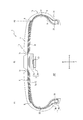
- FIG. 2 is a cross-sectional view in the tire width direction of the single pneumatic tire shown in FIG. It is an expanded sectional view which expands and shows the tread part of the pneumatic tire shown in FIG.
- RF tag as an example of a communication apparatus, and the reader / writer which can be wirelessly communicated with this RF tag.
- FIGS. 1 to 10 An embodiment of a pneumatic tire according to the present invention will be exemplarily described with reference to FIGS. 1 to 10.
- symbol is attached
- FIG. 1 is a view showing an assembly 100 including a pneumatic tire 1 (hereinafter simply referred to as “tire 1”) and a rim 2.
- FIG. 1 is a cross-sectional view showing a cross section parallel to the tire width direction A including the tire rotation axis of the assembly 100 (hereinafter, referred to as “tire width direction cross-sectional view”).
- FIG. 2 is a cross-sectional view in the tire width direction showing the single tire 1 shown in FIG.
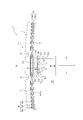
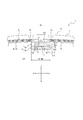
- FIG. 3 is an enlarged cross-sectional view showing a tread portion 1a which is a part of the tire 1 shown in FIG. In other words, the tire 1 shown in FIG. 2 and FIG. 3 shows a state where it is not mounted on the rim 2.
- the tire 1 is attached to the rim 2.
- the assembly 100 has an annular surface formed by the inner surface of the tire 1 (hereinafter, referred to as “tire inner surface”) and the outer surface of the rim 2 (hereinafter, referred to as “rim outer surface”).
- the tire lumen 101 is divided.
- segmented only by tire inner surface in a tire width direction cross sectional view is hereafter described as "in-tire space 102.”
- the rim 2 includes a rim main body 2a on which a bead portion 1c of the tire 1 described later is mounted, and a disc 2b that holds the rim main body 2a and is attached to an axle.
- the rim 2 of the present embodiment is a metal two-piece wheel rim, but is not limited to this, and may be a one-piece rim or the like. Further, the rim body 2a protrudes to the outside in the tire radial direction B from both ends of the rim seat portion 2a1 on which bead members 4 of the tire 1 described later are attached to the outside in the tire radial direction B And a rim flange portion 2a2.
- the tire 1 includes a tread portion 1a, a pair of sidewall portions 1b extending inward in a tire radial direction B from both end portions of the tread portion 1a in the tire width direction A, and an inner side of each sidewall portion 1b in the tire radial direction B. And a pair of bead portions 1c provided at the end of the The tire 1 of the present embodiment is a tubeless type radial tire for passenger cars.
- tread portion 1a refers to two planes P1 parallel to the tire radial direction B passing through the belt ends Q (see FIG. 2) positioned on the outermost sides of the belt 6 in the tire width direction A described later.
- the part (except bead part 1c) pinched by P2 is meant.
- the bead part 1c means the part in which the bead member 4 mentioned later in tire radial direction B is located.
- sidewall part 1b means a portion between tread part 1a and bead part 1c.
- the tire inner surface defining the tire inner cavity 101 is described as the inner surface 31 of the tread portion 1a (hereinafter referred to as “tread inner surface 31”) and the inner surface 32 of the sidewall portion 1b (hereinafter referred to as “sidewall inner surface 32" And an inner surface 33 of the bead portion 1c (hereinafter referred to as “bead inner surface 33").
- the tire 1 includes a noise suppressing body 3, a bead member 4, a carcass 5, a belt 6, a tread rubber 7, side rubbers 8, an inner liner 9, and a communication device 10.
- the noise suppressing body 3 includes a first noise suppressing body 3 a and a second noise suppressing body 3 b.
- the first noise suppressing body 3a is made of a sponge material. Further, the first noise suppressing body 3a is fixed to the inner surface of the tire.
- the second noise suppressing body 3b is made of a sponge material. Further, the second noise suppressing body 3b is disposed on the in-tire space 102 side (the same as the tire inner cavity 101 side in the assembly 100 of FIG. 1) of the first noise suppressing body 3a.
- the tire inner space side of the first noise control body means the side where the tire inner space is located with respect to the first noise control body, and the tire inner surface of the first noise control body. It does not mean only the side opposite to the fixing surface fixed to the. That is, in the present embodiment, the in-tire space 102 side of the first noise control body 3a is the inner side in the tire radial direction B of the first noise control body 3a in the tire width direction sectional view shown in FIG. The lower side) and both sides (the left and right sides in FIG. 3) of the first noise reduction body 3a in the tire width direction A are meant.
- the second noise suppressing body 3b of the present embodiment is disposed on the inner side in the tire radial direction B of the first noise suppressing body 3a as the in-tire space 102 side of the first noise suppressing body 3a.
- the second noise suppressing member may be disposed on one side or both sides in the tire width direction A of the first noise suppressing member 3 a as the tire inner space 102 side of the first noise suppressing member 3 a.
- the second noise suppressing body 3 b is harder than the first noise suppressing body 3 a.
- the term "hardness” as used herein refers to the value measured according to method A in section 6.4 among the methods for measuring "hardness test” in section 6 of JIS K 6400-2 (2012). .
- the communication device 10 is held between the first noise suppressing body 3 a and the second noise suppressing body 3 b. Therefore, by forming the first noise suppressing body 3a with a soft sponge material, the first noise suppressing body 3a absorbs an impact or vibration from the tire inner surface side of the tire 1, and the communication device 10 receives an impact or vibration. Transmission can be suppressed.
- the second noise suppressing body 3b is formed of a hard sponge material, so that the second noise suppressing body 3b is prevented from being deformed by an impact during traveling on a road surface, vibration, air flow in the tire lumen, and the like. can do.
- the second noise suppressing body 3b a sponge material harder than the first noise suppressing body 3a is used as the second noise suppressing body 3b, a sponge material the same as or softer than the first noise suppressing body 3a is used as the second noise suppressing body.
- the durability of the second noise suppressing body 3b can be improved.
- the communication device 10 is held between the first noise suppressing member 3 a and the second noise suppressing member 3 b, the second noise suppressing member 3 b is a cover, and the communication device 10 is on the in-tire space 102 side. It is hard to drop out. Thereby, the position fixability of the communication device 10 can be improved.
- the hardness of the first noise damper 3a and the second noise damper 3b is set to the above-described hardness relationship, and the communication device 10 is provided between the first noise damper 3a and the second noise damper 3b.
- the protection of the communication device 10 by the sponge material by maintaining the configuration, it is possible to realize both the improvement of the position fixing property of the communication device 10 by the sponge material and the improvement of the durability of the sponge material. it can.
- the hardnesses of the first noise suppressing member 3a and the second noise suppressing member 3b made of a sponge material be set in the range of 25N to 55N so as to have the above-described hardness relationship.
- the first noise suppressing member 3a be set in the range of 30N to 50N.
- the second noise suppressing member 3b is set from the range of 35N to 45N.
- the sponge material constituting the first noise suppressing body 3a and the second noise suppressing body 3b is a sponge-like porous structure, and includes, for example, a so-called sponge having open cells in which rubber or synthetic resin is foamed.
- the sponge material includes web-like materials in which animal fibers, plant fibers or synthetic fibers are entangled and integrally connected.
- the above-mentioned "porous structure" is the meaning including not only the structure which has an open cell but the structure which has a closed cell. However, from the viewpoint of sound absorption performance, it is preferable to use a structure having open cells.
- the sponge material as described above absorbs sound by converting the vibrational energy of the air in which the air gap formed on the surface and the inside vibrates into thermal energy. This reduces cavity resonance in the tire lumen.
- the material of the sponge material examples include synthetic polyurethane resin sponges such as ether polyurethane foam, ester polyurethane foam, polyethylene sponge, chloroprene rubber sponge (CR sponge), ethylene propylene rubber sponge (EPDM sponge), nitrile rubber sponge (NBR sponge) And rubber sponges. It is preferable to use a polyurethane-based or polyethylene-based sponge including an ether-based polyurethane sponge, in view of noise suppression properties, lightness, foam adjustability, durability, and the like.
- synthetic polyurethane resin sponges such as ether polyurethane foam, ester polyurethane foam, polyethylene sponge, chloroprene rubber sponge (CR sponge), ethylene propylene rubber sponge (EPDM sponge), nitrile rubber sponge (NBR sponge) And rubber sponges. It is preferable to use a polyurethane-based or polyethylene-based sponge including an ether-based polyurethane sponge, in view of noise suppression properties, lightness, foam adjustability, durability, and the like.
- the specific gravity of the sponge material is preferably in the range of 0.005 to 0.06, preferably 0.01 to 0.04, in consideration of the balance between the increase in tire weight and the effect of reducing cavity resonance noise. It is more preferable to set it to 0.01 to 0.03.
- the volume of the noise suppressing body 3 which is the sum of the volumes of the first noise suppressing body 3 a and the second noise suppressing body 3 b be 0.4% to 20% of the total volume of the tire inner cavity 101. .
- the volume of the noise suppressing body 3 is more preferably 1% or more, more preferably 2% or more, and particularly preferably 4% or more of the entire volume of the tire lumen 101.
- the volume of the noise suppressing body 3 is more preferably 16% or less of the entire volume of the tire lumen 101, and particularly preferably 10% or less.
- first noise suppressing body 3a and the second noise suppressing body 3b will be described later.
- the bead member 4 is embedded in the bead portion 1c.
- the bead member 4 includes a bead core 4a and a rubber bead filler 4b located on the outer side of the bead core 4a in the tire radial direction B.
- the bead core 4a is provided with a plurality of bead wires whose circumference is covered with rubber.
- the bead wire is formed of a steel cord.
- the steel cord can be made of, for example, a monofilament of steel or a stranded wire. In addition, you may use an organic fiber, a carbon fiber, etc. as a bead wire.
- the carcass 5 straddles between the pair of bead portions 1c, more specifically, between the bead cores 4a of the pair of bead members 4, and extends in a toroidal shape.
- the carcass 5 has at least a radial structure.
- the carcass 5 is composed of one or more (one in the present embodiment) carcass plies 5a in which carcass cords are arranged at an angle of 75 ° to 90 ° with respect to the tire circumferential direction C (see FIG. 7).
- the carcass ply 5a includes a ply body located between a pair of bead cores 4a, and a ply turnback which is folded from the inside to the outside in the tire width direction A around the bead cores 4a at both ends of the ply body. ing.
- the bead filler 4b which extends in a tapered shape from the bead core 4a to the outer side in the tire radial direction B is disposed.
- a polyester cord is employed as the carcass cord constituting the carcass ply 5a, but in addition to this, an organic fiber cord such as nylon, rayon or aramid, or a steel cord may be employed if necessary.
- the number of carcass plies 5a may be two or more.
- the belt 6 includes one or more (five in the present embodiment) belt layers disposed on the outer side in the tire radial direction B with respect to the crown portion of the carcass 5. Specifically, as shown in FIG. 3, the belt 6 of the present embodiment includes an inclined belt 6 a and a circumferential belt 6 b.
- the inclined belt 6 a includes one or more (two in this embodiment) inclined belt layers disposed on the outer side in the tire radial direction B with respect to the crown portion of the carcass 5.
- the inclined belt 6a of the present embodiment includes a first inclined belt layer 6a1 and a second inclined belt layer 6a2 stacked in the tire radial direction B.
- Each of the first inclined belt layer 6a1 and the second inclined belt layer 6a2 is a belt ply in which steel cords as metal belt cords are arranged at an angle of 10 ° to 40 ° with respect to the tire circumferential direction C (see FIG. 7). It is formed of The two belt plies are laid one on another with the direction of inclination of the belt cords different from one another.
- the belt cords cross each other between the belt plies, the belt rigidity is enhanced, and the substantially full width of the tread portion 1a can be reinforced by the tag effect.
- the second inclined belt layer 6a2 located outside in the tire radial direction B is formed narrower than the first inclined belt layer 6a1 located inside in the tire radial direction B. Therefore, in the present embodiment, the first inclined belt layer 6a1 located on the inner side in the tire radial direction B extends to the outer side in the tire width direction A more than the second inclined belt layer 6a2 located on the outer side in the tire radial direction B. It exists.
- the first inclined belt layer positioned inside the tire radial direction B may be formed narrower than the second inclined belt layer positioned outside the tire radial direction B. That is, the second inclined belt layer located outside in the tire radial direction B may extend to the outside in the tire width direction A more than the first inclined belt layer located inside in the tire radial direction B.
- the inclined belt 6a may be configured by a belt layer of only one layer, or may be configured by a belt layer of three or more layers.
- the circumferential belt 6b is provided with one or more (three in this embodiment) circumferential belt layers arranged on the outer side in the tire radial direction B with respect to the inclined belt 6a.
- the circumferential belt 6b includes a first circumferential belt layer 6b1, a second circumferential belt layer 6b2 and a third circumferential belt layer 6b3 stacked in the tire radial direction B.
- Each of the first circumferential belt layer 6b1, the second circumferential belt layer 6b2 and the third circumferential belt layer 6b3 has a nylon cord as a belt cord of organic fiber at 10 ° to the tire circumferential direction C (see FIG. 7)
- it is formed of a belt ply spirally wound around the tire rotation axis at an angle of preferably 5 ° or less.
- the circumferential belt 6b of the present embodiment is constituted by three circumferential belt layers arranged on the outer side in the tire radial direction B with respect to the inclined belt 6a.
- the present invention is not limited to this configuration.
- it may be a circumferential belt composed of four or more circumferential belt layers.
- the length relationship between the circumferential belt layers in the tire width direction A, the length relationship between each circumferential belt layer and each inclined belt layer in the tire width direction A, and the positional relationship between belt edges in the circumferential belt layers The positional relationship of the belt end between each circumferential belt layer and each inclined belt layer, etc. can be appropriately designed according to the desired performance without being limited to the configuration of the present embodiment, and the belt structure of the present embodiment It is not limited to
- the tread rubber 7 constitutes a surface on the outer side in the tire radial direction B of the tread portion 1a (hereinafter referred to as "tread outer surface"), and on the tread outer surface in the tire circumferential direction C (see FIG. 7).
- a tread pattern including an extending circumferential groove 7a and a not-shown width direction groove extending in the tire width direction A is formed.
- the side rubber 8 constitutes the outer surface of the sidewall portion 1 b in the tire width direction A, and is integrally formed with the above-described tread rubber 7.
- the inner liner 9 is laminated on the inner surface of the carcass 5 and is made of butyl-based rubber having low air permeability.
- butyl type rubber means butyl rubber and halogenated butyl rubber which is its derivative.
- the first noise suppressing body 3a is fixed to the inner liner 9 by a double-sided adhesive tape, an adhesive or the like. Therefore, in the region of the inner liner 9 to which the first noise suppressing body 3a is fixed, low butyl content in which the compounding amount of the butyl-based rubber is lower than the region to which the first noise suppressing body 3a is not fixed It may be a blending area.
- FIG. 4 is a view showing an RF tag as an example of the communication device 10 and a reader / writer 60 capable of wirelessly communicating with the RF tag.
- the RF tag includes a storage unit 10 a that stores identification information of the tire 1, an antenna unit 10 b that can transmit to and receive from the reader / writer 60 located outside the tire 1, and information to the storage unit 10 a. And a control unit 10c capable of reading information from the storage unit 10a.
- the RF tag as the communication device 10 can receive, from the antenna unit 60a of the reader / writer 60, information transmitted on a radio wave or a magnetic field by the antenna unit 10b.
- Electric power is generated in the antenna unit 10b of the RF tag by rectification (in the case of a radio wave) or resonance (in the case of a magnetic field), and the storage unit 10a and the control unit 10c perform predetermined operations.
- the control unit 10 c reads the information in the storage unit 10 a of the RF tag, puts it on a radio wave or a magnetic field, and sends back (sends) the reader / writer 60 from the antenna unit 10 b.
- the antenna unit 60a of the reader / writer 60 receives a radio wave or a magnetic field from the RF tag.
- the control unit 60b of the reader / writer 60 can acquire the information stored in the storage unit 10a of the RF tag by extracting the received information.
- the storage unit 10a and the control unit 10c described above can be configured by, for example, an integrated circuit (IC chip) including a non-volatile memory.
- the storage unit 10a of the RF tag as the communication device 10 stores, for example, unique identification information of the tire 1 that can specify each tire for each tire, such as a manufacturer of the tire 1, a manufacturing factory, and a manufacturing date. There is.
- the storage unit 10a may store tire history information such as the distance traveled by the tire, the number of times of rapid braking, the number of times of rapid dispatching, and the number of times of sudden turning as rewritable information by the reader / writer 60.
- a sensor that detects a tire internal temperature, a tire internal pressure, a tire acceleration and the like may be provided in the tire bore 101, and the storage unit 10a may store detection information detected by these sensors.
- the RF tag as the communication device 10 can acquire detection information of the sensor by performing wireless communication with the sensor through the antenna unit 10 b.
- the communication device 10 may be configured to wirelessly communicate with a predetermined device outside the tire 1, and is not limited to the above-described RF tag.
- a predetermined device outside the tire 1 For example, an acceleration sensor that detects the acceleration of the tire 1
- the communication device 10 may be an internal pressure sensor that detects the internal pressure of the tire 1 or the like.
- the communication device 10 is not a sensor such as an acceleration sensor, for example, and an RF tag that is not related to the above-mentioned distance element, as the distance element such as tire displacement amount per unit time fluctuates measurement accuracy. Is preferred.
- the RF tag may be distorted due to deformation, impact, vibration or the like of the tire 1 and may be damaged. Therefore, in the case of the RF tag, it is preferable to make the first noise-damping body 3a absorb the impact, vibration and the like from the tire inner surface side of the tire 1 to make it difficult to transmit the impact and vibration to the RF tag.
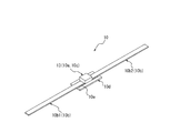
- FIG. 5 and 6 are perspective views showing an RF tag as the communication device 10 according to the present embodiment.
- the RF tag as the communication apparatus 10 of the present embodiment receives the first antenna 10b1 and the second antenna 10b2 constituting the antenna unit 10b, and the first antenna 10b1 and the second antenna 10b2.
- the IC chip 13 constituting the control unit 10c and the storage unit 10a, which operates by the dielectric electromotive force generated by radio waves, the plate-like support member 10d to which the IC chip 13 is attached, the IC chip 13, and the first And a conductive conduction member 10e electrically connecting the antenna 10b1 and the second antenna 10b2 to each other.
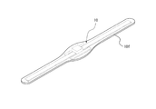
- FIG. 6 is a perspective view showing a state in which the RF tag as the communication device 10 shown in FIG. 5 is covered by the covering portion 10 f.
- the covering portion 10 f is formed of rubber or resin.
- the RF tag as the communication device 10 in a state where the periphery is covered by the covering portion 10 f is held between the first noise suppressing member 3 a and the second noise suppressing member 3 b. It is done.
- the specific configuration of the RF tag as the communication device 10 is not particularly limited as long as it is held between the first noise suppressing body 3a and the second noise suppressing body 3b. . Therefore, the communication device 10 may be configured to be held by being held between the first noise suppressing member 3a and the second noise suppressing member 3b by the first noise suppressing member 3a and the second noise suppressing member 3b. .
- Such a configuration is, for example, a direction along the inner surface of the tire (see FIG. 3 in the tire width direction A) in the tire width direction sectional view (see FIG. 3 etc.) of the first noise suppressing body 3 a and the second noise suppressing body 3 b.
- the fixed devices are fixed at different positions separated in approximately the same direction). , Is feasible. However, it is preferable that the RF tag as the communication device 10 be fixed to at least one of the first noise suppressing body 3 a and the second noise suppressing body 3 b by an adhesive or the like. In this way, position fixability of the communication device 10 can be enhanced.
- the RF tag as the communication device 10 of the present embodiment is fixed to the first noise suppressing body 3 a and the second noise suppressing body 3 b by an adhesive.
- the communication device 10 is fixed to at least the first noise control body 3a, the communication device 10 and the first noise control body 3a are integrated, so that the tire is added to the communication device 10 from the tire inner surface side when traveling on the road surface. Shock, vibration and the like can be always reduced by the first noise control body 3a. Furthermore, when the communication device 10 is fixed not only to the first noise suppressing body 3a but also to the second noise suppressing body 3b, the communication device 10 and the second noise suppressing body 3b are integrated. It is possible to prevent the communication device 10 and the second noise control member 3b from repeatedly colliding with each other due to shocks or vibrations when traveling on a road surface. Thereby, the communication device 10 can be prevented from being damaged or the like, and the durability of the communication device 10 can be improved.
- FIG. 7 is a cross-sectional view taken along the tire equatorial plane CL (hereinafter referred to as “tire circumferential cross-sectional view”) of the tire 1 alone.
- the first noise suppressing body 3 a and the second noise suppressing body 3 b of the present embodiment are strip-shaped members extending over the entire area in the tire circumferential direction C, and any given in the tire circumferential direction C.
- the cross-sectional view in the tire width direction at the position (see FIG. 2 etc.) they have substantially the same cross-sectional outer shape.
- the first noise suppressing member 3 a and the second noise suppressing member 3 b may be provided only in a part of the tire circumferential direction C as long as the communication device 10 is held therebetween.
- the first noise suppressing member 3 a and the second noise suppressing member 3 b are provided over the entire region in the tire circumferential direction C.
- the volume of the sponge material in the tire lumen 101 can be increased as compared with the configuration in which the first noise suppressing member and the second noise suppressing member are provided only in a part of the tire circumferential direction C.
- the cavity resonance of the tire lumen 101 can be further reduced.
- each of the first noise suppressing body 3 a and the second noise suppressing body 3 b has a flat shape in a cross-sectional view in the tire width direction (see FIG. 3 and the like).
- the first noise suppressing body 3a is fixed to the tread inner surface 31 of the tire inner surface, and the maximum thickness T1 (this embodiment) in the orthogonal direction orthogonal to the tire inner surface in the tire width direction cross sectional view (see FIG. 3 etc.). Then, there is a flat shape in which the maximum length W1 in the direction along the tire inner surface (approximately equal to the maximum length in the tire width direction A in this embodiment) is larger than the maximum length in the tire radial direction B). doing.
- the thickness of the first noise reduction body 3a means the length in the orthogonal direction orthogonal to the inner surface of the tire.
- the above-mentioned maximum thickness T1 and maximum length W1 of the first noise suppressing body 3a are obtained by attaching the first noise suppressing body 3a and the second noise suppressing body 3b to the tire 1 and in a state before the rim assembly (normal temperature, It shall be measured under normal pressure).
- the maximum thickness T1 of the first noise suppressing body 3a of this embodiment is set, for example, from 5 mm to 45 mm.
- the first noise suppressing body 3a of the present embodiment has a substantially rectangular cross-sectional outer shape in a tire width direction cross-sectional view (see FIG. 3 and the like).
- the first noise suppressing body 3a of the present embodiment extends along the inner surface of the tire and is fixed to the inner surface of the tire in a cross-sectional view in the tire width direction (see FIG. 3 etc.), and the fixed surface 3a1.
- an inner side 3a2 extending along the inner surface of the tire and substantially parallel to the fixed surface 3a1, and a continuous surface with the fixed surface 3a1 and the inner side 3a2 along the inner surface of the tire (in the present embodiment, the tire width
- An end face 3a3 extending in the orthogonal direction orthogonal to the inner surface of the tire, which is located on both sides of the direction substantially equal to the direction A).
- the second noise suppressing body 3 b is stacked on the surface of the first noise suppressing body 3 a on the tire inner space 102 side.
- the second noise suppressing member 3b has a flat shape in which the maximum length W2 is larger than the maximum thickness T2 in the tire width direction sectional view (see FIG. 3 and the like).
- the thickness of the second noise suppressing body 3b is the length in the direction orthogonal to the portion where the second noise suppressing body 3b is stacked in the surface on the tire inner space 102 side of the first noise suppressing body 3a.
- the maximum thickness T2 of the second noise suppressing member 3b is a portion of the surface of the first noise suppressing member 3a on the tire inner space 102 side where the second noise suppressing member 3b is stacked (in this embodiment, It means the maximum value of the length in the direction orthogonal to a part of the inner surface 3a2.
- the maximum thickness T2 of the second noise suppressing body 3b of this embodiment is equal to the maximum length in the orthogonal direction orthogonal to the inner surface of the tire, and is substantially equal to the maximum length in the tire radial direction B.
- the length of the second noise suppressing body 3 b means the length of the second noise suppressing body 3 b in the direction along the surface of the first noise suppressing body 3 a.
- the maximum length W2 of the second noise reduction body 3b means the maximum value of the length of the second noise reduction body 3b in the direction along the surface of the first noise reduction body 3a.
- the maximum length W2 of the second noise damper 3b of the present embodiment is equal to the maximum length in the direction along the tire inner surface, and is substantially equal to the maximum length in the tire width direction A.
- the above-mentioned maximum thickness T2 and maximum length W2 of the second noise suppressing body 3b are the same as the maximum thickness T1 and maximum length W1 of the first noise suppressing body 3a. [2]
- the noise suppressing body 3b is attached, and it is assumed that the measurement is performed in a state before setting the rim (normal temperature, normal pressure).
- the second noise suppressing member 3b of the present embodiment is at least a part of the inner surface 3a2 of the first noise suppressing member 3a (a part of the inner surface 3a2 in the present embodiment) in the tire width direction sectional view (see FIG. 3 etc.) Only), and the RF tag as the communication device 10 is held between the inner side 3a2 of the first noise suppressing body 3a and the second noise suppressing body 3b.
- the entire thickness of the first noise suppressing body 3a is The shock and vibration from the tire inner surface side can be absorbed by using the same, and it is possible to further enhance the shock absorbing performance that makes it difficult for the communication device 10 to transmit the shock and vibration from the tire inner surface side.
- the second noise suppressing body 3b of the present embodiment has a substantially rectangular cross-sectional outer shape in a cross-sectional view in the tire width direction (see FIG. 3 and the like).
- the second noise suppressing body 3b of the present embodiment faces the inner side surface 3a2 of the first noise suppressing body 3a in the tire width direction cross sectional view (see FIG. 3 and the like), and extends along the tire inner surface.
- a free surface 3b2 located on the opposite side of the facing surface 3b1 and extending substantially parallel to the facing surface 3b1 along the tire inner surface, continuous with the facing surface 3b1 and the free surface 3b2 and extending along the tire inner surface
- an end surface 3b3 extending in a direction orthogonal to the inner surface of the tire is provided, which is located on both sides in the direction substantially equal to the tire width direction A).
- the minimum thickness T3 of the first noise reduction body 3a is equal to or greater than the maximum thickness T2 of the second noise reduction body 3b. More specifically, the minimum thickness T3 of the first noise suppressing body 3a of the present embodiment is thicker than the maximum thickness T2 of the second noise suppressing body 3b.
- the minimum thickness T3 of the first noise damper 3a is increased, an impact or vibration is transmitted to the communication device 10 held between the first noise damper 3a and the second noise damper 3b from the inner surface side of the tire. It can be difficult.
- the second noise suppressing body 3b only needs to suppress separation of small pieces from the surface of the sponge material, as long as it at least constitutes the surface of the sponge material facing the tire inner space 102. Therefore, the maximum thickness T2 of the second noise suppressing body 3b may be thin. As described above, it is desirable that the first noise suppressing member 3a and the second noise suppressing member 3b made of a sponge material have a predetermined volume or more in order to obtain a desired reduction effect of the cavity resonance sound.
- the minimum thickness of the first noise suppressing body 3a while the total thickness of the first noise suppressing body 3a and the second noise suppressing body 3b is equal to or more than a predetermined thickness that can ensure the desired reduction effect of the cavity resonance sound.
- the thickness of the first noise suppressing body 3a of the present embodiment is minimized at the position of the recess 11 described later, and is uniform at positions other than the recess 11. Therefore, the thickness at an arbitrary position other than the concave portion 11 of the first noise suppressing body 3a is the above-mentioned maximum thickness T1. On the other hand, the thickness at the position of the recess 11 of the first noise suppressing body 3a is the above-mentioned minimum thickness T3. Further, since the thickness of the second noise suppressing body 3b in the present embodiment is uniform, the thickness at an arbitrary position of the second noise suppressing body 3b is the above-mentioned maximum thickness T2.
- the maximum length W2 of the second noise suppressing member 3b (approximately equal to the maximum length in the tire width direction A in the present embodiment) is the maximum length W1 of the first noise suppressing member 3a ( In the present embodiment, it is shorter than the maximum length in the tire width direction A). More specifically, the second noise suppressing body 3b of the present embodiment covers only a part of the inner side surface 3a2 of the first noise suppressing body 3a, and in the tire width direction sectional view (see FIG. 3 etc.) It does not extend to the outside of the inner side surface 3a2 of the first noise suppressing body 3a in the direction along the tire inner surface.
- the second noise suppressing body 3b of this embodiment is located in the region where the inner side surface 3a2 of the first noise suppressing body 3a is located in the direction along the tire inner surface in the tire width direction cross section (see FIG. 3 etc.). Located only in. The RF tag as the communication device 10 is held at a position between the inner side surface 3a2 of the first noise suppressing body 3a and the facing surface 3b1 of the second noise suppressing body 3b.
- the length relationship between the maximum length W1 of the first noise suppressing body 3a and the maximum length W2 of the second noise suppressing body 3b is not limited to the above-described length relationship of this embodiment, and, for example, FIG.
- the maximum length W2 of the second noise suppressing member 3b may be equal to or greater than the maximum length W1 of the first noise suppressing member 3a.
- FIG. 8 shows a configuration in which the maximum length W2 of the second noise suppressing member 3b and the maximum length W1 of the first noise suppressing member 3a are substantially equal.
- FIG. 9 shows a configuration in which the maximum length W2 of the second noise damper 3b is longer than the maximum length W1 of the first noise damper 3a and is wound around the end face 3a3 of the first noise damper 3a. .
- the second noise suppressing body 3b shown in FIG. 8 covers the entire area of the inner side surface 3a2 of the first noise suppressing body 3a in the tire width direction sectional view, and the RF tag as the communication device 10 It is held between the inner side surface 3a2 of the first noise suppressing body 3a and the facing surface 3b1 of the second noise suppressing body 3b.
- the sponge material is repeatedly deformed.
- the deformation of the outer edge X of the inner surface 3a2 of the first noise damper 3a is suppressed, and the small piece of sponge material is separated from the outer edge X of the inner surface 3a2 of the first noise barrier 3a. Can be suppressed.
- the second noise suppressing body 3b shown in FIG. 9 covers at least a part of the end face 3a3 of the first noise suppressing body 3a in the tire width direction cross sectional view. That is, the second noise suppressing member 3b shown in FIG. 9 covers not only the entire area of the inner side surface 3a2 but also at least a part of the end surface 3a3 in the tire width direction sectional view. With such a configuration, as compared to the configuration in which the second noise suppressing body 3b covers only the entire inner surface 3a2 as shown in FIG. The area can be further reduced. Therefore, separation of a small piece of sponge material from the surface of the first noise suppressing body 3a can be further suppressed.
- the second noise suppressing body 3b shown in FIG. 9 covers the entire area of the inner side surface 3a2 and the end surface 3a3 of the first noise suppressing body 3a in the tire width direction cross sectional view.
- the entire area of the first noise suppressing body 3a on the tire inner space 102 side shown in FIG. 9 is covered with the second noise suppressing body 3b.
- the second noise suppressing body 3b shown in FIG. 9 is in contact with the inner surface of the tire at positions on both sides in the tire inner surface of the first noise suppressing body 3a in the tire width direction sectional view (see FIG. 9).
- the end face 3b3 of the second noise suppressing body 3b is in contact with the inner surface of the tire.
- the surface of the first noise reduction body 3a exposed to the tire inner space 102 is eliminated. Can.
- the entire surface of the first noise suppressing body 3a facing the in-tire space 102 which is easily deformed and separated into small pieces of the sponge material, is covered by the second noise suppressing body 3b. It is possible to further suppress separation of small pieces of sponge material from the surface of 3a.
- the second noise suppressing body 3b shown in FIG. 9 is, in a cross-sectional view in the tire width direction, a first stacked portion 12a stacked on the inner side surface 3a2 of the first noise suppressing body 3a and the first stacked portion 12a.
- a second laminated portion 12b continuous with one end and stacked on one end face 3a3 of the first noise suppressing body 3a and another end of the first laminated portion 12a continuously with the other end face of the first noise suppressing body 3a
- a third stacked unit 12c stacked in 3a3. Then, the RF tag as the communication device 10 is held between the inner side surface 3a2 of the first noise suppressing body 3a and the facing surface 3b1 at the position of the first laminated portion 12a of the second noise suppressing body 3b. There is.
- the thickness of the second noise suppressing body 3b shown in FIG. 9 is a length in a direction orthogonal to the inner side surface 3a2 at the position of the first laminated portion 12a (in the example shown in FIG. Means equal to the length and approximately equal to the length of the tire radial direction B). Further, the thickness of the second noise suppressing body 3b shown in FIG. 9 is a length in a direction orthogonal to the end face 3a3 at the positions of the second laminated portion 12b and the third laminated portion 12c (in the example of FIG. Approximately equal to the length of A). And maximum thickness T2 of the 2nd noise-sounding body 3b shown in FIG. 9 is a thickness of the position of the 1st lamination
- the RF tag as the communication device 10 of the present embodiment is fixed to the first noise suppressing body 3 a and the second noise suppressing body 3 b. More specifically, the RF tag as the communication device 10 of the present embodiment is fixed by an adhesive to the inner side surface 3a2 of the first noise suppressing body 3a and the facing surface 3b1 of the second noise suppressing body 3b. . Furthermore, the first noise suppressing body 3a of the present embodiment is fixed to the second noise suppressing body 3b on both sides sandwiching the communication device 10 in the direction along the tire inner surface in the tire width direction cross sectional view (see FIG. 3 etc.) It is done. More specifically, in the present embodiment, the communication device 10 in the tire width direction sectional view (see FIG.
- the adhesive is fixed on both sides in the tire width direction A of FIG.
- the tire width direction sectional view In FIG. 3 etc., it can suppress that the communication apparatus 10 moves in the direction (substantially equal to the tire width direction A in this embodiment) in alignment with a tire inner surface. Therefore, the communication device 10 can be prevented from falling off the tire lumen 101.
- each of the first noise suppressing member 3a and the second noise suppressing member 3b shown in FIGS. 3, 8 and 9 has a symmetrical shape with respect to the tire equatorial plane CL. Furthermore, the first noise suppressing member 3a and the second noise suppressing member 3b shown in FIG. 3, FIG. 8 and FIG. 9 are provided only at the position of the tread inner surface 31 in the tire inner surface. With such a configuration, even when the tire 1 is rotating at high speed, the first noise suppressing member 3a and the second noise suppressing member 3b can be formed on the tread inner surface 31 by the centrifugal force acting toward the outside in the tire radial direction B. It can be pressed.
- the communication device 10 is formed between the inner side surface 3a2 of the first noise suppressing body 3a and the opposing surface 3b1 of the second noise suppressing body 3b by the centrifugal force acting outward in the tire radial direction B. As the communication device 10 can be firmly held, the position fixability of the communication device 10 during traveling can be further improved.
- the recess 11 is formed in the first noise suppressing body 3 a, and the RF tag as the communication device 10 is accommodated in the recess 11. More specifically, the recess 11 is formed in the inner side surface 3a2 of the first noise suppressing body 3a, and the RF tag as the communication device 10 shown in FIGS. 5 and 6 is the inner side surface of the first noise suppressing body 3a. It is accommodated in the recessed part 11 of 3a2.
- the recess 11 capable of accommodating the communication device 10 in at least one of the first noise suppressing member 3 a and the second noise suppressing member 3 b, the communication device 10 is less likely to be detached from the recess 11. The position fixability of the device 10 can be further improved.
- the shape of the recess 11 for accommodating the communication device 10 is not limited to the wide shallow groove having a small depth as shown in FIGS. 3, 8 and 9, and, for example, the thin communication device 10 can be inserted.
- the recess 11 may have various shapes such as a narrow slit groove having a deep depth.
- the recessed part 11 is formed in the 1st noise suppressing body 3a, it replaces with the 1st noise suppressing body 3a, and the recessed part 11 is formed in the 2nd noise suppressing body 3b. May be formed. Furthermore, the recess 11 may be formed in each of the first noise suppressing body 3a and the second noise suppressing body 3b. In such a case, the first noise suppressing body 3a and the second noise suppressing body 3a and the second noise reduction so that one cavity for accommodating the communication device 10 is defined by the recesses 11 of both the first noise suppressing body 3a and the second noise suppressing body 3b. Stack the body 3b. In other words, the RF tag as the communication device 10 is accommodated so as to straddle both the recess 11 of the first noise suppressing body 3 a and the recess 11 of the second noise suppressing body 3 b.
- FIG. 10 is an enlarged cross-sectional view of the tread portion 1a of the cross section of the tire 21 alone in the tire width direction.
- the tire 21 of the present embodiment is different from the tire 1 of the first embodiment in the configuration of the second noise suppressing body 3b, but the other configuration is the same. Therefore, here, differences with the tire 1 of the first embodiment will be mainly described, and the description of the same configuration will be omitted.
- a convex-concave shape and a concave-convex shape are formed on the surface of the second noise suppressing body 3b on the tire inner space 102 side. More specifically, the second noise suppressing body 3b of the present embodiment and the first laminated portion 22a stacked on the inner side surface 3a2 of the first noise suppressing body 3a in the tire width direction sectional view (see FIG. 10). A second laminated portion 22b continuous with one end of the first laminated portion 22a and laminated on one end face 3a3 of the first noise damper 3a, and continuous with the other end of the first laminated portion 22a; And a third stacked portion 22c stacked on the other end face 3a3 of the noise suppressing body 3a.
- the surface on the tire inner space 102 side of the second noise suppressing body 3b of this embodiment is the free surface 3b2, and the free surface 3b2 is a surface on the inner side of the first laminated portion 22a in the tire radial direction B, It is comprised by the surface of the outer side of the tire width direction A of 2 laminated part 22b, and the surface of the outer side of the tire width direction A of 3rd laminated part 22c. Then, the surface on the inner side in the tire radial direction B of the first laminated portion 22a as the surface on the tire inner space 102 side of the second noise control body 3b extends in the tire circumferential direction C (see FIG.
- One convex rib 23 as a convex portion and a concave groove 24 as a concave portion partitioned between the two convex ribs 23 are formed. Further, one convex rib 23 is also formed on the outer surface of the second laminated portion 22b in the tire width direction A, which is the surface on the tire inner space 102 side of the second noise suppressing body 3b. Similarly, one convex rib 23 is formed also on the outer surface of the third laminated portion 22c in the tire width direction A, which is the surface on the tire inner space 102 side of the second noise control body 3b.
- the concavo-convex shape formed on the surface on the tire inner space 102 side of the second noise suppressing body 3b of the present embodiment is a plurality of convex ribs 23 and a concave groove partitioned between the plurality of convex ribs 23. And 24 are configured.
- the surface of the second noise suppressing body 3b on the side of the in-tire space 102 has a concavo-convex shape, so that the sound is easily irregularly reflected, and the cavity resonance noise can be reduced.
- the surface area of the free surface 3b2 facing the in-tire space 102 of the second noise suppressing body 3b can be increased, the heat radiation performance from the free surface 3b2 of the second noise suppressing body 3b can be enhanced.
- convex ribs 23 of this embodiment are arrange
- the configuration extends in the tire circumferential direction C (see FIG. 7).
- the present invention is not limited to this configuration, and a plurality of tires are arranged at intervals in the tire circumferential direction C (see FIG. 7). It may be configured to extend to A.
- the present invention relates to a pneumatic tire.
- 1 Pneumatic tire, 1a: tread portion, 1b: sidewall portion, 1c: bead portion, 2: rim, 2a: rim main body, 2a1: rim seat portion, 2a2: rim flange portion, 2b: disc, 3: noise control Body 3a: first noise control body 3a1: fixed surface, 3a2: inner surface, 3a3: end surface, 3b: second noise control body, 3b1: facing surface, 3b2: free surface, 3b3: end surface, 4: bead member , 4a: bead core, 4b: bead filler, 5: carcass, 5a: carcass ply, 6: belt, 6a: inclined belt, 6a1: first inclined belt layer, 6a2: second inclined belt layer, 6b: circumferential belt, 6b1 1st circumferential belt layer 6b2 2nd circumferential belt layer 6b 3 3rd circumferential belt layer 7 tread rubber 7 : Circumferential groove, 8: side rubber, 9: inner
Landscapes
- Engineering & Computer Science (AREA)
- Mechanical Engineering (AREA)
- Computer Hardware Design (AREA)
- Microelectronics & Electronic Packaging (AREA)
- Physics & Mathematics (AREA)
- General Physics & Mathematics (AREA)
- Theoretical Computer Science (AREA)
- Tires In General (AREA)
Abstract
本発明に係る空気入りタイヤは、タイヤ内面に固着されている、スポンジ材からなる第1制音体と、前記第1制音体のタイヤ内空間側に配置されている、スポンジ材からなる第2制音体と、前記第1制音体と前記第2制音体との間で保持されている通信装置と、を備え、前記第2制音体は、前記第1制音体よりも硬い。
Description
本発明は空気入りタイヤに関する。
従来から、タイヤの空気圧などのタイヤの内部状態を検出するセンサや、タイヤの固有識別情報等を記憶可能な記憶部を備えるRFタグなど、の通信装置をタイヤ内面に取り付ける構成、又は、タイヤ内部に埋め込む構成、が知られている。例えば、通信装置としてのセンサにより、走行中のタイヤの状態を判定したり、通信装置としてのRFタグの記憶部から取得されるさまざまなタイヤ情報を保守サービス等に活用したりすることができる。
特許文献1には、無線タグを、タイヤ内面に固着されているスポンジ材に取り付ける構成が開示されている。また、特許文献2には、タイヤ内面に固着する帯状シートを、吸音性能に優れる第1のスポンジ材からなる第1層と、音の反射防止性能に優れる第2のスポンジ材からなる第2層と、の多層構造体として形成することが開示されている。
特許文献1及び特許文献2に記載されているように、空気入りタイヤ及びリムで区画されるタイヤ内腔にスポンジ材を配置することにより、空洞共鳴エネルギーを別のエネルギーに変換等して吸音し、空洞共鳴音を低減することができる。更に、特許文献1では、通信装置としての無線タグを、スポンジ材に取り付けることにより、無線タグを衝撃や振動などから保護している。
しかしながら、特許文献1に記載の構成では、走行中の衝撃や振動等により、無線タグがスポンジ材からタイヤ内腔に脱落するおそれが依然としてある。そのため、スポンジ材による無線タグの位置固定性を向上させることが好ましい。また、無線タグを衝撃や振動等から保護すべく、スポンジ材を軟質の材料で形成すると、スポンジ材は、走行時の衝撃、振動、タイヤ内腔の気流、等により変形し易くなる。スポンジ材が繰り返し変形すると、スポンジ材の表面からスポンジ材の小片が分離する破損が生じ易く、分離したスポンジ材の小片が、タイヤ内腔に散らばるおそれがある。
そこで本発明は、スポンジ材による通信装置の保護に加えて、スポンジ材による通信装置の位置固定性の向上と、スポンジ材の耐久性の向上と、の両立を実現可能な構成を備える、空気入りタイヤを提供することを目的とする。
本発明の一態様としての空気入りタイヤは、タイヤ内面に固着されている、スポンジ材からなる第1制音体と、前記第1制音体のタイヤ内空間側に配置されている、スポンジ材からなる第2制音体と、前記第1制音体と前記第2制音体との間で保持されている通信装置と、を備え、前記第2制音体は、前記第1制音体よりも硬い。
本発明によれば、スポンジ材による通信装置の保護に加えて、スポンジ材による通信装置の位置固定性の向上と、スポンジ材の耐久性の向上と、の両立を実現可能な構成を備える、空気入りタイヤを提供することができる。
以下、本発明に係る空気入りタイヤの実施形態について、図1~図10を参照して例示説明する。各図において共通する部材・部位には同一の符号を付している。
<<第1実施形態>>
図1は、空気入りタイヤ1(以下、単に「タイヤ1」と記載する。)と、リム2と、を備える組立体100を示す図である。具体的に、図1は、組立体100の、タイヤ回転軸を含み、タイヤ幅方向Aに平行な、断面を示す断面図(以下、「タイヤ幅方向断面図」と記載する。)である。図2は、図1に示すタイヤ1単体を示すタイヤ幅方向断面図である。図3は、図2に示すタイヤ1の一部であるトレッド部1aを拡大して示す拡大断面図である。換言すれば、図2及び図3に示すタイヤ1は、リム2に装着されていない状態を示している。
図1は、空気入りタイヤ1(以下、単に「タイヤ1」と記載する。)と、リム2と、を備える組立体100を示す図である。具体的に、図1は、組立体100の、タイヤ回転軸を含み、タイヤ幅方向Aに平行な、断面を示す断面図(以下、「タイヤ幅方向断面図」と記載する。)である。図2は、図1に示すタイヤ1単体を示すタイヤ幅方向断面図である。図3は、図2に示すタイヤ1の一部であるトレッド部1aを拡大して示す拡大断面図である。換言すれば、図2及び図3に示すタイヤ1は、リム2に装着されていない状態を示している。
図1に示すように、組立体100において、タイヤ1は、リム2に装着されている。組立体100は、タイヤ1の内面(以下、「タイヤ内面」と記載する。)とリム2の外面(以下、「リム外面」と記載する。)とで構成されるタイヤ内腔面により、環状のタイヤ内腔101を区画している。なお、図2に示すように、タイヤ幅方向断面視において、タイヤ内面のみにより区画される、タイヤ径方向Bの内側が開放されている空間を、以下「タイヤ内空間102」と記載する。
<リム2>
リム2は、タイヤ1の後述するビード部1cが装着されるリム本体2aと、このリム本体2aを保持し車軸に取り付けられるディスク2bと、を備えている。本実施形態のリム2は、金属製の2ピースホイールリムであるが、これに限定されるものではなく、1ピースリム等としてもよい。また、リム本体2aは、タイヤ1の後述するビード部材4がタイヤ径方向Bの外側に取り付けられるリムシート部2a1と、このリムシート部2a1のタイヤ幅方向Aの両端からタイヤ径方向Bの外側に突出するリムフランジ部2a2と、を備えている。
リム2は、タイヤ1の後述するビード部1cが装着されるリム本体2aと、このリム本体2aを保持し車軸に取り付けられるディスク2bと、を備えている。本実施形態のリム2は、金属製の2ピースホイールリムであるが、これに限定されるものではなく、1ピースリム等としてもよい。また、リム本体2aは、タイヤ1の後述するビード部材4がタイヤ径方向Bの外側に取り付けられるリムシート部2a1と、このリムシート部2a1のタイヤ幅方向Aの両端からタイヤ径方向Bの外側に突出するリムフランジ部2a2と、を備えている。
<タイヤ1>
タイヤ1は、トレッド部1aと、このトレッド部1aのタイヤ幅方向Aの両端部からタイヤ径方向Bの内側に延びる一対のサイドウォール部1bと、各サイドウォール部1bのタイヤ径方向Bの内側の端部に設けられた一対のビード部1cと、を備えている。本実施形態のタイヤ1は、チューブレスタイプの乗用車用ラジアルタイヤである。ここで「トレッド部1a」とは、後述するベルト6のタイヤ幅方向A両側の最も外側に位置するベルト端Q(図2参照)をそれぞれ通過するタイヤ径方向Bに平行する2つの平面P1、P2に挟まれる部分(ビード部1cを除く)を意味する。また、「ビード部1c」とは、タイヤ径方向Bにおいて後述するビード部材4が位置する部分を意味する。そして「サイドウォール部1b」とは、トレッド部1aとビード部1cとの間の部分を意味する。
タイヤ1は、トレッド部1aと、このトレッド部1aのタイヤ幅方向Aの両端部からタイヤ径方向Bの内側に延びる一対のサイドウォール部1bと、各サイドウォール部1bのタイヤ径方向Bの内側の端部に設けられた一対のビード部1cと、を備えている。本実施形態のタイヤ1は、チューブレスタイプの乗用車用ラジアルタイヤである。ここで「トレッド部1a」とは、後述するベルト6のタイヤ幅方向A両側の最も外側に位置するベルト端Q(図2参照)をそれぞれ通過するタイヤ径方向Bに平行する2つの平面P1、P2に挟まれる部分(ビード部1cを除く)を意味する。また、「ビード部1c」とは、タイヤ径方向Bにおいて後述するビード部材4が位置する部分を意味する。そして「サイドウォール部1b」とは、トレッド部1aとビード部1cとの間の部分を意味する。
タイヤ内腔101を区画するタイヤ内面は、トレッド部1aの内面31(以下、「トレッド内面31」と記載する。)と、サイドウォール部1bの内面32(以下、「サイドウォール内面32」と記載する。)と、ビード部1cの内面33(以下、「ビード内面33」と記載する。)と、を備えている。
タイヤ1は、制音体3、ビード部材4、カーカス5、ベルト6、トレッドゴム7、サイドゴム8、インナーライナ9、及び、通信装置10、を備えている。
[制音体3]
制音体3は、第1制音体3a及び第2制音体3bを備えている。第1制音体3aは、スポンジ材により構成されている。また、第1制音体3aは、タイヤ内面に固着されている。第2制音体3bは、スポンジ材により構成されている。また、第2制音体3bは、第1制音体3aのタイヤ内空間102側(図1の組立体100ではタイヤ内腔101側と同じ)に配置されている。タイヤ内腔101に、スポンジ材からなる、第1制音体3a及び第2制音体3bを配置することにより、タイヤ内腔101の空洞共鳴音を低減することができる。
制音体3は、第1制音体3a及び第2制音体3bを備えている。第1制音体3aは、スポンジ材により構成されている。また、第1制音体3aは、タイヤ内面に固着されている。第2制音体3bは、スポンジ材により構成されている。また、第2制音体3bは、第1制音体3aのタイヤ内空間102側(図1の組立体100ではタイヤ内腔101側と同じ)に配置されている。タイヤ内腔101に、スポンジ材からなる、第1制音体3a及び第2制音体3bを配置することにより、タイヤ内腔101の空洞共鳴音を低減することができる。
ここで、「第1制音体のタイヤ内空間側」とは、第1制音体に対して、タイヤ内空間が位置する側を意味しており、第1制音体のうち、タイヤ内面に固着されている固着面と反対の面側のみを意味するものではない。すなわち、本実施形態において、第1制音体3aのタイヤ内空間102側とは、図3に示すタイヤ幅方向断面視において、第1制音体3aのタイヤ径方向Bの内側(図3では下側)、及び、第1制音体3aのタイヤ幅方向Aの両側(図3では左右両側)、を意味している。本実施形態の第2制音体3bは、第1制音体3aのタイヤ内空間102側としての、第1制音体3aのタイヤ径方向Bの内側に、配置されているが、この構成に限らず、第1制音体3aのタイヤ内空間102側としての、第1制音体3aのタイヤ幅方向Aの片側又は両側に、配置されている第2制音体としてもよい。
第2制音体3bは、第1制音体3aよりも硬い。ここで言う「硬さ」とは、JIS K6400-2(2012)の第6項の「硬さ試験」の測定法のうち、6.4項のA法に準拠して測定された値とする。
後述するように、通信装置10は、第1制音体3aと第2制音体3bとの間で保持されている。そのため、第1制音体3aを軟質のスポンジ材で形成することにより、第1制音体3aがタイヤ1のタイヤ内面側からの衝撃や振動などを吸収し、通信装置10に衝撃や振動が伝わることを抑制することができる。その一方で、第2制音体3bを硬質のスポンジ材で形成することにより、第2制音体3bが、路面走行時の衝撃、振動、タイヤ内腔の気流、等により変形することを抑制することができる。そのため、第2制音体3bの表面からスポンジ材の小片が分離する破損が発生し難くなる。つまり、第2制音体3bとして、第1制音体3aよりも硬いスポンジ材を用いれば、第2制音体として第1制音体3aと同じ又は軟らかいスポンジ材を用いる構成と比較して、第2制音体3bの耐久性を向上させることができる。更に、通信装置10が、第1制音体3aと第2制音体3bとの間で保持されているため、第2制音体3bがカバーとなり、通信装置10がタイヤ内空間102側に脱落し難い。これにより、通信装置10の位置固定性を向上させることができる。
このように、第1制音体3a及び第2制音体3bの硬さを上述の硬さ関係にすると共に、第1制音体3a及び第2制音体3bの間で通信装置10を保持する構成とすることにより、スポンジ材による通信装置10の保護に加えて、スポンジ材による通信装置10の位置固定性の向上と、スポンジ材の耐久性の向上と、の両立を実現することができる。
スポンジ材からなる第1制音体3a及び第2制音体3bの硬さは、25N~55Nの範囲で、上述の硬さ関係となるように設定されることが好ましい。特に、第1制音体3aは、30N~50Nの範囲から設定されることが好ましい。また、第2制音体3bは、35N~45Nの範囲から設定されることが好ましい。
第1制音体3a及び第2制音体3bを構成するスポンジ材は、海綿状の多孔構造体であり、例えばゴムや合成樹脂を発泡させた連続気泡を有する所謂スポンジを含む。また、スポンジ材は、上述のスポンジの他に、動物繊維、植物繊維又は合成繊維等を絡み合わせて一体に連結したウエブ状のものを含む。なお、上述の「多孔構造体」は、連続気泡を有する構造体に限らず、独立気泡を有する構造体も含む意味である。但し、吸音性能の観点では、連続気泡を有する構造体を用いることが好ましい。
上述のようなスポンジ材は、表面や内部に形成される空隙が振動する空気の振動エネルギーを熱エネルギーに変換することにより吸音する。これにより、タイヤ内腔での空洞共鳴音が低減される。
スポンジ材の材料としては、例えば、エーテル系ポリウレタンスポンジ、エステル系ポリウレタンスポンジ、ポリエチレンスポンジなどの合成樹脂スポンジ、クロロプレンゴムスポンジ(CRスポンジ)、エチレンプロピレンゴムスポンジ(EPDMスポンジ)、ニトリルゴムスポンジ(NBRスポンジ)などのゴムスポンジが挙げられる。制音性、軽量性、発泡の調節可能性、耐久性などの観点を考慮すれば、エーテル系ポリウレタンスポンジを含むポリウレタン系又はポリエチレン系等のスポンジを用いることが好ましい。
また、スポンジ材の比重は、タイヤ重量の増加と空洞共鳴音を低減する効果との両方のバランスを考慮し、0.005~0.06とすることが好ましく、0.01~0.04とすることがより好ましく、0.01~0.03とすることが特に好ましい。
更に、第1制音体3aと第2制音体3bとの体積の和である制音体3の体積は、タイヤ内腔101の全体積の0.4%~20%とすることが好ましい。タイヤ内腔の全体積に対して制音体3の体積を0.4%以上確保することにより、所望量(例えば2dB以上)の空洞共鳴音の低減効果を実現し易い。制音体3の体積は、タイヤ内腔101の全体積の1%以上とすることがより好ましく、2%以上とすることが更に好ましく、4%以上とすることが特に好ましい。その一方、制音体3の体積がタイヤ内腔101の全体積の20%を超えるように構成しても空洞共鳴音の低減効果の向上が期待できない。むしろ組立体100の重量バランスを悪化させる可能性がある。このような観点より、制音体3の体積は、タイヤ内腔101の全体積の16%以下とすることがより好ましく、10%以下とすることが特に好ましい。
第1制音体3a及び第2制音体3bの更なる詳細については後述する。
[ビード部材4]
ビード部材4は、ビード部1cに埋設されている。ビード部材4は、ビードコア4aと、このビードコア4aに対してタイヤ径方向Bの外側に位置するゴム製のビードフィラ4bと、を備えている。ビードコア4aは、周囲をゴムにより被覆されている複数のビードワイヤを備えている。ビードワイヤはスチールコードにより形成されている。スチールコードは、例えば、スチールのモノフィラメント又は撚り線からなるものとすることができる。なお、ビードワイヤとして、有機繊維やカーボン繊維等を用いてもよい。
ビード部材4は、ビード部1cに埋設されている。ビード部材4は、ビードコア4aと、このビードコア4aに対してタイヤ径方向Bの外側に位置するゴム製のビードフィラ4bと、を備えている。ビードコア4aは、周囲をゴムにより被覆されている複数のビードワイヤを備えている。ビードワイヤはスチールコードにより形成されている。スチールコードは、例えば、スチールのモノフィラメント又は撚り線からなるものとすることができる。なお、ビードワイヤとして、有機繊維やカーボン繊維等を用いてもよい。
[カーカス5]
カーカス5は、一対のビード部1c間、より具体的には一対のビード部材4のビードコア4a間に跨っており、トロイダル状に延在している。また、カーカス5は、少なくともラジアル構造を有している。
カーカス5は、一対のビード部1c間、より具体的には一対のビード部材4のビードコア4a間に跨っており、トロイダル状に延在している。また、カーカス5は、少なくともラジアル構造を有している。
更に、カーカス5は、カーカスコードをタイヤ周方向C(図7参照)に対して例えば75°~90゜の角度で配列した1枚以上(本実施形態では1枚)のカーカスプライ5aから構成されている。このカーカスプライ5aは、一対のビードコア4a間に位置するプライ本体部と、このプライ本体部の両端で、ビードコア4aの廻りでタイヤ幅方向Aの内側から外側に折り返されるプライ折返し部と、を備えている。そして、プライ本体部とプライ折返し部との間には、ビードコア4aからタイヤ径方向Bの外側に先細状に延びるビードフィラ4bが配置されている。カーカスプライ5aを構成するカーカスコードとして、本実施形態ではポリエステルコードを採用しているが、これ以外にもナイロン、レーヨン、アラミドなどの有機繊維コードや、必要によりスチールコードを採用してもよい。また、カーカスプライ5aの枚数についても、2枚以上としてもよい。
[ベルト6]
ベルト6は、カーカス5のクラウン部に対してタイヤ径方向Bの外側に配置されている1層以上(本実施形態では5層)のベルト層を備えている。具体的には、図3に示すように、本実施形態のベルト6は、傾斜ベルト6aと、周方向ベルト6bと、を備えている。
ベルト6は、カーカス5のクラウン部に対してタイヤ径方向Bの外側に配置されている1層以上(本実施形態では5層)のベルト層を備えている。具体的には、図3に示すように、本実施形態のベルト6は、傾斜ベルト6aと、周方向ベルト6bと、を備えている。
図2に示すように、傾斜ベルト6aは、カーカス5のクラウン部に対してタイヤ径方向Bの外側に配置されている1層以上(本実施形態では2層)の傾斜ベルト層を備えている。より具体的に、本実施形態の傾斜ベルト6aは、タイヤ径方向Bに積層されている、第1傾斜ベルト層6a1及び第2傾斜ベルト層6a2、を備えている。第1傾斜ベルト層6a1及び第2傾斜ベルト層6a2それぞれは、金属のベルトコードとしてのスチールコードをタイヤ周方向C(図7参照)に対して10°~40°の角度で傾斜配列したベルトプライから形成されている。2枚のベルトプライは、ベルトコードの傾斜の向きを互いに違えて重ね置きされている。そのため、ベルトコードがベルトプライ間相互で交差し、ベルト剛性が高められ、トレッド部1aの略全幅をタガ効果により補強することができる。本実施形態では、タイヤ径方向Bの外側に位置する第2傾斜ベルト層6a2を、タイヤ径方向Bの内側に位置する第1傾斜ベルト層6a1と比較し狭幅に形成している。そのため、本実施形態では、タイヤ径方向Bの内側に位置する第1傾斜ベルト層6a1は、タイヤ径方向Bの外側に位置する第2傾斜ベルト層6a2よりも、タイヤ幅方向Aの外側まで延在している。
但し、タイヤ径方向Bの内側に位置する第1傾斜ベルト層を、タイヤ径方向Bの外側に位置する第2傾斜ベルト層と比較し狭幅に形成してもよい。つまり、タイヤ径方向Bの外側に位置する第2傾斜ベルト層が、タイヤ径方向Bの内側に位置する第1傾斜ベルト層よりも、タイヤ幅方向Aの外側まで延在する構成としてもよい。また、傾斜ベルト6aは、1層のみのベルト層で構成してもよく、3層以上のベルト層で構成してもよい。
図2に示すように、周方向ベルト6bは、傾斜ベルト6aに対してタイヤ径方向Bの外側に配置されている1層以上(本実施形態では3層)の周方向ベルト層を備えている。より具体的に、周方向ベルト6bは、タイヤ径方向Bに積層されている、第1周方向ベルト層6b1、第2周方向ベルト層6b2及び第3周方向ベルト層6b3、を備えている。第1周方向ベルト層6b1、第2周方向ベルト層6b2及び第3周方向ベルト層6b3それぞれは、有機繊維のベルトコードとしてのナイロンコードをタイヤ周方向C(図7参照)に対して10°以下、好ましくは5°以下の角度で、タイヤ回転軸回りに、螺旋状に巻回させたベルトプライから形成されている。
本実施形態の周方向ベルト6bは、傾斜ベルト6aに対してタイヤ径方向Bの外側に配置されている3層の周方向ベルト層により構成されているが、この構成に限らず、2層以下又は4層以上の周方向ベルト層からなる周方向ベルトとしてもよい。また、周方向ベルト層同士のタイヤ幅方向Aの長さ関係、各周方向ベルト層と各傾斜ベルト層とのタイヤ幅方向Aの長さ関係、周方向ベルト層同士でのベルト端の位置関係、各周方向ベルト層と各傾斜ベルト層とでのベルト端の位置関係、等は、本実施形態の構成に限らず、所望の性能に応じて適宜設計可能であり、本実施形態のベルト構造に限られるものではない。
[トレッドゴム7及びサイドゴム8]
トレッドゴム7は、トレッド部1aのタイヤ径方向Bの外側の面(以下、「トレッド外面」と記載する。)を構成しており、トレッド外面には、タイヤ周方向C(図7参照)に延在する周方向溝7aや、タイヤ幅方向Aに延在する、図示しない幅方向溝等、を含むトレッドパターンが形成されている。サイドゴム8は、サイドウォール部1bのタイヤ幅方向Aの外側の面を構成しており、上述のトレッドゴム7と一体で形成されている。
トレッドゴム7は、トレッド部1aのタイヤ径方向Bの外側の面(以下、「トレッド外面」と記載する。)を構成しており、トレッド外面には、タイヤ周方向C(図7参照)に延在する周方向溝7aや、タイヤ幅方向Aに延在する、図示しない幅方向溝等、を含むトレッドパターンが形成されている。サイドゴム8は、サイドウォール部1bのタイヤ幅方向Aの外側の面を構成しており、上述のトレッドゴム7と一体で形成されている。
[インナーライナ9]
インナーライナ9は、カーカス5の内面に積層されており、空気透過性の低いブチル系ゴムにより形成されている。なお、ブチル系ゴムとは、ブチルゴム、及びその誘導体であるハロゲン化ブチルゴムを意味する。また、第1制音体3aは、このインナーライナ9に対して、両面粘着テープや接着剤等により、固着されている。そのため、インナーライナ9のうち、第1制音体3aが固着される領域を、接着性の向上のため、第1制音体3aが固着されない領域よりもブチル系ゴムの配合量が低い低ブチル配合領域としてもよい。
インナーライナ9は、カーカス5の内面に積層されており、空気透過性の低いブチル系ゴムにより形成されている。なお、ブチル系ゴムとは、ブチルゴム、及びその誘導体であるハロゲン化ブチルゴムを意味する。また、第1制音体3aは、このインナーライナ9に対して、両面粘着テープや接着剤等により、固着されている。そのため、インナーライナ9のうち、第1制音体3aが固着される領域を、接着性の向上のため、第1制音体3aが固着されない領域よりもブチル系ゴムの配合量が低い低ブチル配合領域としてもよい。
[通信装置10]
通信装置10は、第1制音体3aと第2制音体3bとの間で保持されている。通信装置10は、タイヤ1の外部の所定の装置と無線通信可能な構成であればよく、通信装置10の構成は特に限定されるものではない。図4は、通信装置10の一例としてのRFタグと、このRFタグと無線通信可能なリーダ/ライタ60と、を示す図である。図4に示すように、RFタグは、タイヤ1の識別情報を記憶する記憶部10aと、タイヤ1の外部に位置するリーダ/ライタ60と送受信可能なアンテナ部10bと、記憶部10aへの情報の書き込み、及び、記憶部10aからの情報の読み出しが可能な制御部10cと、を備えるパッシブ型のRFタグとすることが好ましい。具体的に、通信装置10としてのRFタグは、リーダ/ライタ60のアンテナ部60aから、電波又は磁界に乗せて送信される情報を、アンテナ部10bにより受信可能である。整流(電波の場合)または共振(磁界の場合)により、RFタグのアンテナ部10bに電力が発生し、記憶部10a及び制御部10cが所定の動作を行う。例えば、制御部10cは、RFタグの記憶部10a内の情報を読み出し、電波または磁界に乗せてアンテナ部10bから、リーダ/ライタ60に返信(送信)する。リーダ/ライタ60のアンテナ部60aは、RFタグからの電波又は磁界を受信する。リーダ/ライタ60の制御部60bは、受信した情報を取り出すことで、RFタグの記憶部10aに記憶されている情報を取得することができる。なお、上述の記憶部10a及び制御部10cは、例えば、不揮発性メモリを含む集積回路(ICチップ)により構成することができる。
通信装置10は、第1制音体3aと第2制音体3bとの間で保持されている。通信装置10は、タイヤ1の外部の所定の装置と無線通信可能な構成であればよく、通信装置10の構成は特に限定されるものではない。図4は、通信装置10の一例としてのRFタグと、このRFタグと無線通信可能なリーダ/ライタ60と、を示す図である。図4に示すように、RFタグは、タイヤ1の識別情報を記憶する記憶部10aと、タイヤ1の外部に位置するリーダ/ライタ60と送受信可能なアンテナ部10bと、記憶部10aへの情報の書き込み、及び、記憶部10aからの情報の読み出しが可能な制御部10cと、を備えるパッシブ型のRFタグとすることが好ましい。具体的に、通信装置10としてのRFタグは、リーダ/ライタ60のアンテナ部60aから、電波又は磁界に乗せて送信される情報を、アンテナ部10bにより受信可能である。整流(電波の場合)または共振(磁界の場合)により、RFタグのアンテナ部10bに電力が発生し、記憶部10a及び制御部10cが所定の動作を行う。例えば、制御部10cは、RFタグの記憶部10a内の情報を読み出し、電波または磁界に乗せてアンテナ部10bから、リーダ/ライタ60に返信(送信)する。リーダ/ライタ60のアンテナ部60aは、RFタグからの電波又は磁界を受信する。リーダ/ライタ60の制御部60bは、受信した情報を取り出すことで、RFタグの記憶部10aに記憶されている情報を取得することができる。なお、上述の記憶部10a及び制御部10cは、例えば、不揮発性メモリを含む集積回路(ICチップ)により構成することができる。
通信装置10としてのRFタグの記憶部10aは、例えば、タイヤ1の製造メーカ、製造工場、製造年月日等の、各タイヤをタイヤ毎に特定できるタイヤ1の固有の識別情報を記憶している。また、記憶部10aに、リーダ/ライタ60により書き換え可能な情報として、タイヤの走行距離、急制動回数、急発信回数、急旋回回数等のタイヤ履歴情報を記憶させてもよい。更に、例えば、タイヤ内部温度、タイヤ内圧、タイヤ加速度等を検出するセンサがタイヤ内腔101に設けられており、記憶部10aが、これらセンサにより検出された検出情報を記憶してもよい。通信装置10としてのRFタグは、アンテナ部10bを通じて、センサと無線通信することで、センサの検出情報を取得することができる。
なお、上述したように、通信装置10は、タイヤ1の外部の所定の装置と無線通信可能な構成であればよく、上述のRFタグに限らず、例えば、タイヤ1の加速度を検出する加速度センサや、タイヤ1の内圧を検出する内圧センサ等を通信装置10としてもよい。但し、通信装置10としては、単位時間当たりのタイヤ変位量などの距離的要素により測定精度が変動する、例えば加速度センサなどのセンサではなく、上述の距離的要素とは関係しないRFタグとすることが好ましい。加速度センサ等の距離的要素により測定精度が変動するセンサは、第1制音体3aによりタイヤ変位が吸収されると、高精度な測定ができないおそれがあるためである。その一方でRFタグは、タイヤ1の変形、衝撃、振動等により歪が生じて破損するおそれがある。そのため、RFタグの場合には、タイヤ1のタイヤ内面側からの衝撃や振動などを第1制音体3aで吸収させ、RFタグに衝撃や振動が伝わり難くすることが好ましい。
図5、図6は、本実施形態の通信装置10としてのRFタグを示す斜視図である。図5に示すように、本実施形態の通信装置10としてのRFタグは、アンテナ部10bを構成する第1アンテナ10b1及び第2アンテナ10b2と、これら第1アンテナ10b1及び第2アンテナ10b2で受信する電波により発生する誘電起電力により稼働する、制御部10c及び記憶部10aを構成するICチップ13と、このICチップ13が取り付けられている板状の支持部材10dと、ICチップ13と、第1アンテナ10b1及び第2アンテナ10b2それぞれと、を電気的に接続する導電性の導通部材10eと、を備えている。図6は、図5に示す通信装置10としてのRFタグが、被覆部10fにより被覆されている状態を示す斜視図である。被覆部10fは、ゴム又は樹脂から形成されている。本実施形態では、図6に示すように周囲が被覆部10fにより被覆されている状態の、通信装置10としてのRFタグが、第1制音体3a及び第2制音体3bの間で保持されている。
なお、通信装置10としてのRFタグは、第1制音体3a及び第2制音体3bの間で保持されている構成であれば、保持する具体的構成については特に限定されるものではない。したがって、通信装置10を、第1制音体3aと第2制音体3bとの間で、第1制音体3a及び第2制音体3bにより挟持することにより、保持する構成としてもよい。このような構成は、例えば、第1制音体3aと第2制音体3bを、タイヤ幅方向断面視(図3等参照)において、タイヤ内面に沿う方向(図3ではタイヤ幅方向Aに略等しい方向)の離れた別々の位置で固着し、通信装置10としてのRFタグを、第1制音体3a及び第2制音体3bが固着されていない箇所に挟持させて保持させることにより、実現可能である。但し、通信装置10としてのRFタグは、第1制音体3a及び第2制音体3bの少なくとも一方に、接着剤等により、固着されていることが好ましい。このようにすれば、通信装置10の位置固定性を高めることができる。本実施形態の通信装置10としてのRFタグは、第1制音体3a及び第2制音体3bに対して、接着剤により固着されている。通信装置10が少なくとも第1制音体3aに固着している構成とすれば、通信装置10と第1制音体3aとが一体化するため、路面走行時にタイヤ内面側から通信装置10に加わる衝撃、振動等を、第1制音体3aにより常時軽減することができる。更に、通信装置10が、第1制音体3aのみならず、第2制音体3bにも固着されている構成とすれば、通信装置10と第2制音体3bとが一体化するため、路面走行時の衝撃や振動等により、通信装置10と第2制音体3bとが繰り返し衝突することを防ぐことができる。これにより、通信装置10が破損等することを抑制することができ、通信装置10の耐久性を向上させることができる。
[第1制音体3a及び第2制音体3b]
次に、第1制音体3a及び第2制音体3bの構成の詳細について説明する。
次に、第1制音体3a及び第2制音体3bの構成の詳細について説明する。
図7は、タイヤ1単体についてのタイヤ赤道面CLに沿う断面図(以下、「タイヤ周方向断面図」と記載する。)である。図7に示すように、本実施形態の第1制音体3a及び第2制音体3bは、タイヤ周方向Cの全域に亘って延在する帯状部材であり、タイヤ周方向Cの任意の位置でのタイヤ幅方向断面図(図2等参照)において、略同一の断面外形を有している。第1制音体3a及び第2制音体3bは、その間に通信装置10が保持されていれば、タイヤ周方向Cの一部のみに設けられていてもよい。但し、本実施形態のように、第1制音体3a及び第2制音体3bを、タイヤ周方向Cの全域に亘って設けることが好ましい。このようにすれば、第1制音体及び第2制音体をタイヤ周方向Cの一部のみに設ける構成と比較して、タイヤ内腔101内でのスポンジ材の体積を増加させることができ、タイヤ内腔101の空洞共鳴音を、より低減することができる。
本実施形態において、第1制音体3a及び第2制音体3bそれぞれは、タイヤ幅方向断面視(図3等参照)において扁平形状を有している。
第1制音体3aは、タイヤ内面のうちトレッド内面31に固着されており、タイヤ幅方向断面視(図3等参照)において、タイヤ内面と直交する直交方向の最大厚さT1(本実施形態ではタイヤ径方向Bの最大長さに略等しい)よりも、タイヤ内面に沿う方向の最大長さW1(本実施形態ではタイヤ幅方向Aの最大長さに略等しい)が大きい、扁平形状を有している。なお、第1制音体3aの厚さとは、タイヤ内面と直交する直交方向の長さを意味する。
第1制音体3aの上述の最大厚さT1及び最大長さW1は、タイヤ1に第1制音体3a及び第2制音体3bが取り付けられ、かつ、リム組前の状態(常温、常圧下)で測定されるものとする。本実施形態の第1制音体3aの最大厚さT1は、例えば、5mm~45mmから設定される。
より具体的に、本実施形態の第1制音体3aは、タイヤ幅方向断面視(図3等参照)において、略長方形の断面外形を有している。本実施形態の第1制音体3aは、タイヤ幅方向断面視(図3等参照)において、タイヤ内面に沿って延在し、タイヤ内面と固着されている固着面3a1と、この固着面3a1と反対側に位置し、タイヤ内面に沿って固着面3a1と略平行に延在する内側面3a2と、固着面3a1及び内側面3a2と連続し、タイヤ内面に沿う方向(本実施形態ではタイヤ幅方向Aと略等しい方向)の両側にそれぞれ位置する、タイヤ内面に対して直交する直交方向に延在する端面3a3と、を備えている。
第2制音体3bは、第1制音体3aのタイヤ内空間102側の面に積層されている。そして、第2制音体3bは、タイヤ幅方向断面視(図3等参照)において、最大厚さT2よりも、最大長さW2が大きい、扁平形状を有している。ここで、第2制音体3bの厚さとは、第1制音体3aのタイヤ内空間102側の面のうち、第2制音体3bが積層されている部分と直交する方向の長さを意味する。そして、第2制音体3bの最大厚さT2とは、第1制音体3aのタイヤ内空間102側の面のうち、第2制音体3bが積層されている部分(本実施形態では内側面3a2の一部)と直交する方向の長さの最大値を意味する。なお、本実施形態の第2制音体3bの最大厚さT2は、タイヤ内面に直交する直交方向の最大長さに等しく、かつ、タイヤ径方向Bの最大長さに略等しい。また、第2制音体3bの長さとは、第2制音体3bの、第1制音体3aの面に沿う方向の長さを意味する。そして、第2制音体3bの最大長さW2とは、第2制音体3bの、第1制音体3aの面に沿う方向の長さの最大値を意味する。本実施形態の第2制音体3bの最大長さW2は、タイヤ内面に沿う方向の最大長さに等しく、かつ、タイヤ幅方向Aの最大長さに略等しい。
第2制音体3bの上述の最大厚さT2及び最大長さW2は、第1制音体3aの最大厚さT1及び最大長さW1と同様、タイヤ1に第1制音体3a及び第2制音体3bが取り付けられ、かつ、リム組前の状態(常温、常圧下)で測定されるものとする。
本実施形態の第2制音体3bは、タイヤ幅方向断面視(図3等参照)において、第1制音体3aの内側面3a2の少なくとも一部(本実施形態では内側面3a2の一部のみ)を覆っており、通信装置10としてのRFタグは、第1制音体3aの内側面3a2と第2制音体3bとの間で保持されている。このような構成とすれば、第1制音体3aの端面3a3と第2制音体3bとの間で通信装置を保持する構成と比較して、第1制音体3aの厚さ全体を利用して、タイヤ内面側からの衝撃や振動を吸収することができ、通信装置10に対して、タイヤ内面側から衝撃や振動が伝わり難くする緩衝性能を、より高めることができる。
より具体的に、本実施形態の第2制音体3bは、タイヤ幅方向断面視(図3等参照)において、略長方形の断面外形を有している。本実施形態の第2制音体3bは、タイヤ幅方向断面視(図3等参照)において、第1制音体3aの内側面3a2と対向し、タイヤ内面に沿って延在する対向面3b1と、この対向面3b1と反対側に位置し、タイヤ内面に沿って対向面3b1と略平行に延在する自由面3b2と、対向面3b1及び自由面3b2と連続し、タイヤ内面に沿う方向(本実施形態ではタイヤ幅方向Aと略等しい方向)の両側にそれぞれ位置する、タイヤ内面に対して直交する直交方向に延在する端面3b3と、を備えている。
ここで、本実施形態において、第1制音体3aの最小厚さT3は、第2制音体3bの最大厚さT2以上である。より具体的に、本実施形態の第1制音体3aの最小厚さT3は、第2制音体3bの最大厚さT2よりも厚い。
第1制音体3aの最小厚さT3を厚くすれば、第1制音体3a及び第2制音体3bの間に保持されている通信装置10に、タイヤ内面側から衝撃や振動が伝わり難くすることができる。その一方で、第2制音体3bは、スポンジ材の表面から小片が分離することを抑制できればよく、タイヤ内空間102に面しているスポンジ材の表面を少なくとも構成するものであればよい。したがって、第2制音体3bの最大厚さT2は薄くてもよい。上述したように、スポンジ材からなる第1制音体3a及び第2制音体3bは、所望の空洞共鳴音の低減効果を得るために、所定の体積以上とすることが望ましい。そのため、第1制音体3a及び第2制音体3bの総合厚さを、所望の空洞共鳴音の低減効果を確保できる所定の厚さ以上としつつ、第1制音体3aの最小厚さT3を、第2制音体3bの最大厚さT2以上とすることにより、スポンジ材による通信装置10の位置固定性の向上と、スポンジ材の耐久性の向上と、の両立の実現に加えて、通信装置10に対して、タイヤ内面側から衝撃や振動が伝わり難くする緩衝性能を、より一層高めることができる。
なお、本実施形態の第1制音体3aの厚さは、後述する凹部11の位置で最小となり、凹部11以外の位置では一様である。そのため、第1制音体3aの凹部11以外の任意の位置での厚さが、上述の最大厚さT1となる。その一方で、第1制音体3aの凹部11の位置での厚さが、上述の最小厚さT3となる。また、本実施形態の第2制音体3bの厚さは一様であるため、第2制音体3bの任意の位置での厚さが、上述の最大厚さT2となる。
ここで、本実施形態では、第2制音体3bの最大長さW2(本実施形態ではタイヤ幅方向Aの最大長さに略等しい)は、第1制音体3aの最大長さW1(本実施形態ではタイヤ幅方向Aの最大長さに略等しい)よりも短い。より具体的に、本実施形態の第2制音体3bは、第1制音体3aの内側面3a2の一部のみを覆っており、かつ、タイヤ幅方向断面視(図3等参照)のタイヤ内面に沿う方向において、第1制音体3aの内側面3a2の外側まで延在していない。換言すれば、本実施形態の第2制音体3bは、タイヤ幅方向断面視(図3等参照)のタイヤ内面に沿う方向において、第1制音体3aの内側面3a2が位置する領域内にのみ位置している。そして、通信装置10としてのRFタグは、第1制音体3aの内側面3a2と、第2制音体3bの対向面3b1と、の間の位置で保持されている。
第1制音体3aの最大長さW1及び第2制音体3bの最大長さW2の長さ関係は、本実施形態の上述の長さ関係に限られるものではなく、例えば、図8、図9に示す変形例のように、第2制音体3bの最大長さW2が、第1制音体3aの最大長さW1以上である構成としてもよい。図8は、第2制音体3bの最大長さW2と、第1制音体3aの最大長さW1と、が略等しい構成を示している。図9は、第2制音体3bの最大長さW2が、第1制音体3aの最大長さW1よりも長く、第1制音体3aの端面3a3に巻き付いている構成を示している。
換言すれば、図8に示す第2制音体3bは、タイヤ幅方向断面視において、第1制音体3aの内側面3a2の全域を覆っており、通信装置10としてのRFタグは、第1制音体3aの内側面3a2と第2制音体3bの対向面3b1との間で保持されている。このように、第2制音体3bが、タイヤ幅方向断面視(図8参照)において、第1制音体3aの内側面3a2の全域を覆う構成とすれば、繰り返し変形することによりスポンジ材の小片が特に分離し易い、第1制音体3aの内側面3a2の外縁部X、の変形を抑制し、第1制音体3aの内側面3a2の外縁部Xからスポンジ材の小片が分離することを抑制することができる。
また、図9に示す第2制音体3bは、タイヤ幅方向断面視において、第1制音体3aのうち、端面3a3の少なくとも一部を覆っている。つまり、図9に示す第2制音体3bは、タイヤ幅方向断面視において、内側面3a2全域のみならず、端面3a3の少なくとも一部を覆っている。このような構成とすれば、図8に示すような、第2制音体3bが内側面3a2全域のみを覆う構成と比較して、第1制音体3aのうちタイヤ内空間102に露出する面積を更に低減することができる。そのため、第1制音体3aの表面からスポンジ材の小片が分離することを、より抑制することができる。
より具体的に、図9に示す第2制音体3bは、タイヤ幅方向断面視において、第1制音体3aの内側面3a2及び端面3a3の全域を覆っている。換言すれば、図9に示す第1制音体3aのタイヤ内空間102側の全域が、第2制音体3bにより覆われている。そして、図9に示す第2制音体3bは、タイヤ幅方向断面視(図9参照)において、第1制音体3aのタイヤ内面に沿う方向の両側の位置で、タイヤ内面に接触している。図9に示す例では、第2制音体3bの端面3b3が、タイヤ内面に接触している。このように、第1制音体3aのタイヤ内空間102側の全域を、第2制音体3bにより覆うことにより、第1制音体3aのうちタイヤ内空間102に露出する面を無くすことができる。これにより、変形してスポンジ材の小片が分離し易い、タイヤ内空間102に面する、第1制音体3aの表面全てが、第2制音体3bにより覆われるため、第1制音体3aの表面からスポンジ材の小片が分離することを、より一層抑制することができる。
なお、図9に示す第2制音体3bは、タイヤ幅方向断面視において、第1制音体3aの内側面3a2に積層されている第1積層部12aと、この第1積層部12aの一端と連続し、第1制音体3aの一方の端面3a3に積層されている第2積層部12bと、第1積層部12aの他端と連続し、第1制音体3aの他方の端面3a3に積層されている第3積層部12cと、を備えている。そして、通信装置10としてのRFタグは、第1制音体3aの内側面3a2と、第2制音体3bの第1積層部12aの位置での対向面3b1と、の間で保持されている。
また、図9に示す第2制音体3bの厚さは、第1積層部12aの位置では、内側面3a2に直交する方向の長さ(図9の例ではタイヤ内面に直交する直交方向の長さに等しく、かつ、タイヤ径方向Bの長さに略等しい)を意味する。また、図9に示す第2制音体3bの厚さは、第2積層部12b及び第3積層部12cの位置では、端面3a3に直交する方向の長さ(図9の例ではタイヤ幅方向Aの長さに略等しい)である。そして、図9に示す第2制音体3bの最大厚さT2は、第1積層部12aの位置の厚さである。
上述したように、本実施形態の通信装置10としてのRFタグは、前記第1制音体3a及び第2制音体3bに固着されている。より具体的に、本実施形態の通信装置10としてのRFタグは、第1制音体3aの内側面3a2と、第2制音体3bの対向面3b1と、に接着剤により固着されている。更に、本実施形態の第1制音体3aは、タイヤ幅方向断面視(図3等参照)において、タイヤ内面に沿う方向の、通信装置10を挟む両側で、第2制音体3bと固着されている。より具体的に、本実施形態では、第1制音体3aの内側面3a2と第2制音体3bの対向面3b1とが、タイヤ幅方向断面視(図3等参照)において、通信装置10のタイヤ幅方向Aの両側で、接着剤により固着されている。このような構成とすれば、通信装置10と第1制音体3a及び第2制音体3bそれぞれとの接着が剥離するような事態が発生した場合であっても、タイヤ幅方向断面視(図3等参照)において、通信装置10が、タイヤ内面に沿う方向(本実施形態ではタイヤ幅方向Aに略等しい)に移動することを、抑制することができる。そのため、通信装置10がタイヤ内腔101に脱落することを抑制することができる。
また、図3、図8、図9に示す第1制音体3a及び第2制音体3bそれぞれは、タイヤ赤道面CLに対して対称な形状を有している。更に、図3、図8、図9に示す第1制音体3a及び第2制音体3bは、タイヤ内面のうちトレッド内面31の位置のみに設けられている。このような構成とすれば、タイヤ1の高速回転時においても、タイヤ径方向Bの外側に向かって作用する遠心力によって、第1制音体3a及び第2制音体3bをトレッド内面31に押し付けることができる。そのため、第1制音体3a及び第2制音体3bの動きを効果的に拘束し易くなる。つまり、第1制音体3a及び第2制音体3bをトレッド内面31に固着することにより、より小さい固定力で、第1制音体3a及び第2制音体3bの固定外れを抑制することができる。更に、タイヤ径方向Bの外側に向かって作用する遠心力により、第1制音体3aの内側面3a2と第2制音体3bの対向面3b1との間で通信装置10としてのRFタグを強く挟み込むことができるため、通信装置10の走行時の位置固定性を、より一層向上させることができる。
更に、図3、図8、図9に示す例では、第1制音体3aに凹部11が形成されており、通信装置10としてのRFタグは、凹部11に収容されている。より具体的に、第1制音体3aの内側面3a2には凹部11が形成されており、図5及び図6に示す通信装置10としてのRFタグは、第1制音体3aの内側面3a2の凹部11に収容されている。そして、第1制音体3aの内側面3a2のうち凹部11以外の部分が、第2制音体3bの対向面3b1と当接した状態とされると共に、第2制音体3bの対向面3b1に、接着剤等により、固着されている。このように、第1制音体3a及び第2制音体3bの少なくとも一方に、通信装置10を収容可能な凹部11を形成することにより、通信装置10が凹部11から脱離し難くなり、通信装置10の位置固定性を、より向上させることができる。
なお、通信装置10を収容する凹部11の形状は、図3、図8、図9に示すような広幅で深さが浅い浅溝に限らず、例えば、薄肉の通信装置10を差し込み可能な、狭幅で深さが深いスリット溝など、各種形状を有する凹部11とすることができる。
また、図3、図8、図9に示す例では、第1制音体3aに凹部11が形成されているが、第1制音体3aに代えて、第2制音体3bに凹部11を形成してもよい。更に、第1制音体3a及び第2制音体3bそれぞれに凹部11を形成してもよい。かかる場合には、第1制音体3a及び第2制音体3bの両方の凹部11により通信装置10を収容する1つの空洞を区画するように、第1制音体3a及び第2制音体3bを積層する。換言すれば、通信装置10としてのRFタグは、第1制音体3aの凹部11と、第2制音体3bの凹部11と、の両方に跨るように収容される。
<<第2実施形態>>
次に、第2実施形態としての空気入りタイヤ21(以下、「タイヤ21」と記載する。)について、図10を参照して説明する。図10は、タイヤ21単体のタイヤ幅方向断面のうち、トレッド部1aを拡大した拡大断面図である。本実施形態のタイヤ21は、上述の第1実施形態のタイヤ1と比較して、第2制音体3bの構成が相違しているが、その他の構成は同一である。したがって、ここでは主に、第1実施形態のタイヤ1との相違点について説明し、同一の構成については説明を省略する。
次に、第2実施形態としての空気入りタイヤ21(以下、「タイヤ21」と記載する。)について、図10を参照して説明する。図10は、タイヤ21単体のタイヤ幅方向断面のうち、トレッド部1aを拡大した拡大断面図である。本実施形態のタイヤ21は、上述の第1実施形態のタイヤ1と比較して、第2制音体3bの構成が相違しているが、その他の構成は同一である。したがって、ここでは主に、第1実施形態のタイヤ1との相違点について説明し、同一の構成については説明を省略する。
本実施形態において、第2制音体3bのタイヤ内空間102側の面には、凸部及び凹部による凹凸形状が形成されている。より具体的に、本実施形態の第2制音体3bは、タイヤ幅方向断面視(図10参照)において、第1制音体3aの内側面3a2に積層されている第1積層部22aと、この第1積層部22aの一端と連続し、第1制音体3aの一方の端面3a3に積層されている第2積層部22bと、第1積層部22aの他端と連続し、第1制音体3aの他方の端面3a3に積層されている第3積層部22cと、を備えている。また、本実施形態の第2制音体3bのタイヤ内空間102側の面は、自由面3b2であり、この自由面3b2は、第1積層部22aのタイヤ径方向Bの内側の面、第2積層部22bのタイヤ幅方向Aの外側の面、及び、第3積層部22cのタイヤ幅方向Aの外側の面、により構成されている。そして、第2制音体3bのタイヤ内空間102側の面としての、第1積層部22aのタイヤ径方向Bの内側の面には、タイヤ周方向C(図7参照)に延在する2つの、凸部としての凸リブ23と、これら2つの凸リブ23間に区画される、凹部としての凹溝24と、が形成されている。また、第2制音体3bのタイヤ内空間102側の面としての、第2積層部22bのタイヤ幅方向Aの外側の面にも、1つの凸リブ23が形成されている。同様に、第2制音体3bのタイヤ内空間102側の面としての、第3積層部22cのタイヤ幅方向Aの外側の面にも、1つの凸リブ23が形成されている。このように、本実施形態の第2制音体3bのタイヤ内空間102側の面に形成されている凹凸形状は、複数の凸リブ23と、複数の凸リブ23間に区画される凹溝24と、により構成されている。このような構成とすれば、第2制音体3bのタイヤ内空間102側の面が凹凸形状を有するため、音が乱反射し易く、空洞共鳴音を低減することができる。また、第2制音体3bのタイヤ内空間102に面する自由面3b2の表面積を大きくすることができるため、第2制音体3bの自由面3b2からの放熱性能を高めることができる。
なお、本実施形態の凸リブ23は、タイヤ幅方向断面視(図10参照)において、第1制音体3aのタイヤ内空間102側の面に沿って間隔を空けて4つ配置され、それぞれが、タイヤ周方向C(図7参照)に延在する構成であるが、この構成に限らず、タイヤ周方向C(図7参照)に間隔を空けて複数配置され、それぞれが、タイヤ幅方向Aに延在する構成としてもよい。また、タイヤ幅方向A及びタイヤ周方向Cに点在する凸部としてもよい。
本発明に係る空気入りタイヤは、上述した実施形態及び変形例に示す具体的な構成に限られず、特許請求の範囲を逸脱しない限り、種々の変形・変更が可能である。
本発明は空気入りタイヤに関する。
1:空気入りタイヤ、 1a:トレッド部、 1b:サイドウォール部、 1c:ビード部、 2:リム、 2a:リム本体、 2a1:リムシート部、 2a2:リムフランジ部、 2b:ディスク、 3:制音体、 3a:第1制音体、 3a1:固着面、 3a2:内側面、 3a3:端面、 3b:第2制音体、 3b1:対向面、 3b2:自由面、 3b3:端面、 4:ビード部材、 4a:ビードコア、 4b:ビードフィラ、 5:カーカス、 5a:カーカスプライ、 6:ベルト、 6a:傾斜ベルト、 6a1:第1傾斜ベルト層、 6a2:第2傾斜ベルト層、 6b:周方向ベルト、 6b1:第1周方向ベルト層、 6b2:第2周方向ベルト層、 6b3:第3周方向ベルト層、 7:トレッドゴム、 7a:周方向溝、 8:サイドゴム、 9:インナーライナ、 10:通信装置、 10a:記憶部、 10b:アンテナ部、 10b1:第1アンテナ、 10b2:第2アンテナ、 10c:制御部、 10d:支持部材、 10e:導通部材、 10f:被覆部、 11:凹部、 12a:第1積層部、 12b:第2積層部、 12c:第3積層部、 13:ICチップ、 21:空気入りタイヤ、 22a:第1積層部、 22b:第2積層部、 22c:第3積層部、 23:凸リブ、 24:凹溝、 31:トレッド内面(タイヤ内面)、 32:サイドウォール内面(タイヤ内面)、 33:ビード内面(タイヤ内面)、 60:リーダ/ライタ、 60a:アンテナ部、 60b:制御部、 100:組立体、 101:タイヤ内腔、 102:タイヤ内空間、 A:タイヤ幅方向、 B:タイヤ径方向、 C:タイヤ周方向、 P1、P2:ベルトのタイヤ幅方向における両側の幅方向最外ベルト端を通過する、タイヤ径方向に平行する平面、 Q:ベルト端、 T1:第1制音体の最大厚さ、 T2:第2制音体の最大厚さ、 T3:第1制音体の最小厚さ、 W1:第1制音体の最大長さ、 W2:第2制音体の最大長さ、 X:第1制音体の内側面の外縁部、 CL:タイヤ赤道面
Claims (13)
- タイヤ内面に固着されている、スポンジ材からなる第1制音体と、
前記第1制音体のタイヤ内空間側に配置されている、スポンジ材からなる第2制音体と、
前記第1制音体と前記第2制音体との間で保持されている通信装置と、を備え、
前記第2制音体は、前記第1制音体よりも硬い、空気入りタイヤ。 - 前記第2制音体は、タイヤ幅方向断面視において、前記第1制音体のうち、前記タイヤ内面に固着されている固着面と反対側に位置する内側面の少なくとも一部を覆っており、
前記通信装置は、前記第1制音体の前記内側面と前記第2制音体との間で保持されている、請求項1に記載の空気入りタイヤ。 - タイヤ幅方向断面視において、前記第1制音体の最小厚さは、前記第2制音体の最大厚さ以上である、請求項2に記載の空気入りタイヤ。
- 前記第2制音体は、タイヤ幅方向断面視において、前記第1制音体の前記内側面の全域を覆っている、請求項2又は3に記載の空気入りタイヤ。
- 前記第2制音体は、タイヤ幅方向断面視において、前記第1制音体のうち、前記内側面と連続し、前記タイヤ内面に沿う方向の両側に位置する、端面の少なくとも一部を覆っている、請求項4に記載の空気入りタイヤ。
- 前記第2制音体は、タイヤ幅方向断面視において、前記第1制音体の前記内側面及び前記端面の全域を覆っている、請求項5に記載の空気入りタイヤ。
- 前記第1制音体は、タイヤ幅方向断面視において、前記タイヤ内面に沿う方向の、前記通信装置を挟む両側で、前記第2制音体と固着されている、請求項2乃至6のいずれか1つに記載の空気入りタイヤ。
- 前記第1制音体及び前記第2制音体は、タイヤ周方向の全域に亘って延在している、請求項1乃至7のいずれか1つに記載の空気入りタイヤ。
- 前記第2制音体の前記タイヤ内空間側の面には、凹凸形状が形成されている、請求項1乃至8のいずれか1つに記載の空気入りタイヤ。
- 前記凹凸形状は、タイヤ周方向に延在する複数の凸リブと、前記複数の凸リブ間に区画される凹溝と、により構成されている、請求項9に記載の空気入りタイヤ。
- 前記通信装置は、前記第1制音体及び前記第2制音体の少なくとも一方に固着されている、請求項1乃至10のいずれか1つに記載の空気入りタイヤ。
- 前記第1制音体及び前記第2制音体の少なくとも一方には凹部が形成されており、
前記通信装置は、前記凹部に収容されている、請求項1乃至11のいずれか1つに記載の空気入りタイヤ。 - 前記通信装置は、RFタグである、請求項1乃至12のいずれか1つに記載の空気入りタイヤ。
Priority Applications (4)
| Application Number | Priority Date | Filing Date | Title |
|---|---|---|---|
| EP18838366.5A EP3659819B1 (en) | 2017-07-24 | 2018-06-27 | Pneumatic tire |
| CN201880048768.2A CN110944852B (zh) | 2017-07-24 | 2018-06-27 | 充气轮胎 |
| US16/631,258 US11446967B2 (en) | 2017-07-24 | 2018-06-27 | Pneumatic tire |
| US17/818,000 US20220371384A1 (en) | 2017-07-24 | 2022-08-08 | Pneumatic tire |
Applications Claiming Priority (2)
| Application Number | Priority Date | Filing Date | Title |
|---|---|---|---|
| JP2017-143043 | 2017-07-24 | ||
| JP2017143043A JP6917232B2 (ja) | 2017-07-24 | 2017-07-24 | 空気入りタイヤ |
Related Child Applications (2)
| Application Number | Title | Priority Date | Filing Date |
|---|---|---|---|
| US16/631,258 A-371-Of-International US11446967B2 (en) | 2017-07-24 | 2018-06-27 | Pneumatic tire |
| US17/818,000 Continuation US20220371384A1 (en) | 2017-07-24 | 2022-08-08 | Pneumatic tire |
Publications (1)
| Publication Number | Publication Date |
|---|---|
| WO2019021730A1 true WO2019021730A1 (ja) | 2019-01-31 |
Family
ID=65040071
Family Applications (1)
| Application Number | Title | Priority Date | Filing Date |
|---|---|---|---|
| PCT/JP2018/024441 Ceased WO2019021730A1 (ja) | 2017-07-24 | 2018-06-27 | 空気入りタイヤ |
Country Status (5)
| Country | Link |
|---|---|
| US (2) | US11446967B2 (ja) |
| EP (1) | EP3659819B1 (ja) |
| JP (1) | JP6917232B2 (ja) |
| CN (1) | CN110944852B (ja) |
| WO (1) | WO2019021730A1 (ja) |
Cited By (1)
| Publication number | Priority date | Publication date | Assignee | Title |
|---|---|---|---|---|
| CN114761260A (zh) * | 2019-12-19 | 2022-07-15 | 倍耐力轮胎股份公司 | 包括监测装置的摩托车轮胎 |
Families Citing this family (11)
| Publication number | Priority date | Publication date | Assignee | Title |
|---|---|---|---|---|
| US20220055424A1 (en) * | 2018-12-10 | 2022-02-24 | Pirelli Tyre S.P.A. | Tyre with monitoring device |
| KR102023044B1 (ko) * | 2019-04-22 | 2019-09-19 | 주식회사 폼웍스 | 적층형 타이어 흡음용 프로파일 |
| JP7800190B2 (ja) * | 2021-04-22 | 2026-01-16 | 住友ゴム工業株式会社 | 空気入りタイヤ |
| JP7569283B2 (ja) * | 2021-06-30 | 2024-10-17 | 株式会社ブリヂストン | 空気入りタイヤ |
| KR102598497B1 (ko) * | 2021-09-27 | 2023-11-07 | 넥센타이어 주식회사 | 타이어 |
| JP7699531B2 (ja) * | 2021-12-13 | 2025-06-27 | 株式会社ブリヂストン | タイヤ、及びタイヤ製造方法 |
| JP7695182B2 (ja) * | 2021-12-13 | 2025-06-18 | 株式会社ブリヂストン | タイヤ |
| KR102635117B1 (ko) * | 2021-12-15 | 2024-02-13 | 넥센타이어 주식회사 | 타이어 및 타이어 제조 방법 |
| WO2025126567A1 (ja) * | 2023-12-12 | 2025-06-19 | 株式会社ブリヂストン | タイヤ及び非空気入りタイヤ |
| JP2025093602A (ja) * | 2023-12-12 | 2025-06-24 | 株式会社ブリヂストン | タイヤ |
| CN121816277A (zh) * | 2023-12-12 | 2026-04-07 | 株式会社普利司通 | 轮胎及非充气轮胎 |
Citations (8)
| Publication number | Priority date | Publication date | Assignee | Title |
|---|---|---|---|---|
| JPS621899B2 (ja) | 1977-06-10 | 1987-01-16 | Broken Hill Pty Co Ltd | |
| JP2007176403A (ja) | 2005-12-28 | 2007-07-12 | Sumitomo Rubber Ind Ltd | タイヤ用無線タグ装着部材、空気入りタイヤならびに空気入りタイヤとリムとの組立体 |
| JP2007290699A (ja) * | 2006-04-25 | 2007-11-08 | Soc De Technologie Michelin | タイヤ監視部品用の支持体、支持体および監視部品システム、タイヤ、ならびに車輪 |
| JP2009137497A (ja) * | 2007-12-07 | 2009-06-25 | Bridgestone Corp | 電子部品取付け部材およびタイヤ内面への電子部品取り付け方法。 |
| JP2010125920A (ja) * | 2008-11-26 | 2010-06-10 | Alps Electric Co Ltd | タイヤ情報送信機の取付け構造 |
| JP2010179888A (ja) * | 2009-02-09 | 2010-08-19 | Bridgestone Corp | 空気入りタイヤ |
| JP2013112342A (ja) * | 2011-11-29 | 2013-06-10 | Goodyear Tire & Rubber Co:The | 電子装置または他の物品を空気タイヤに取り付けるシステム |
| DE102015217479A1 (de) * | 2015-09-14 | 2017-03-16 | Continental Reifen Deutschland Gmbh | Fahrzeugreifen mit einem Reifenmodul |
Family Cites Families (16)
| Publication number | Priority date | Publication date | Assignee | Title |
|---|---|---|---|---|
| US5500065A (en) * | 1994-06-03 | 1996-03-19 | Bridgestone/Firestone, Inc. | Method for embedding a monitoring device within a tire during manufacture |
| JP3621899B2 (ja) | 2001-08-28 | 2005-02-16 | 住友ゴム工業株式会社 | 空気入りタイヤとリムとの組立体 |
| JP2004276809A (ja) * | 2003-03-17 | 2004-10-07 | Honda Motor Co Ltd | 車両用車輪 |
| ES2292984T3 (es) | 2003-06-12 | 2008-03-16 | Pirelli Tyre S.P.A. | Neumatico equipado con un dispositivo de monitorizacion, y procedimiento para instalar el dispositivo sobre la superficie interior del neumatico. |
| KR101100065B1 (ko) * | 2003-08-04 | 2011-12-29 | 미쯔비시 지도샤 고교 가부시끼가이샤 | 저소음 공기 타이어 |
| JP4599150B2 (ja) * | 2004-12-14 | 2010-12-15 | 住友ゴム工業株式会社 | 電子部品の収納具を具える空気入りタイヤ |
| JP4330550B2 (ja) * | 2005-04-28 | 2009-09-16 | 住友ゴム工業株式会社 | 空気入りタイヤとリムとの組立体 |
| DE102005023974A1 (de) * | 2005-05-20 | 2006-11-23 | Continental Aktiengesellschaft | Fahrzeugreifen |
| JP4833783B2 (ja) * | 2006-09-26 | 2011-12-07 | 横浜ゴム株式会社 | タイヤ騒音低減装置及び空気入りタイヤ |
| DE102007001279B4 (de) * | 2007-01-08 | 2021-02-11 | Continental Reifen Deutschland Gmbh | Fahrzeugluftreifen mit einem Elektronikmodul |
| JP5685047B2 (ja) | 2010-10-15 | 2015-03-18 | 住友ゴム工業株式会社 | 空気入りタイヤ |
| WO2013153088A1 (de) * | 2012-04-11 | 2013-10-17 | Huf Hülsbeck & Fürst Gmbh & Co. Kg | Reifenmodul mit piezoelektrischem wandler und damit ausgestatteter reifen |
| JP6120887B2 (ja) * | 2014-04-25 | 2017-04-26 | クムホ タイヤ カンパニー インコーポレイテッドKumho Tire Co.,Inc. | 空洞共鳴音低減タイヤ |
| DE102015217472A1 (de) * | 2015-09-14 | 2017-03-16 | Continental Reifen Deutschland Gmbh | Fahrzeugreifen mit einem Reifenmodul |
| EP3431309B1 (en) * | 2016-12-28 | 2020-05-13 | Sumitomo Rubber Industries, Ltd. | Pneumatic tire |
| JP2018141839A (ja) * | 2017-02-27 | 2018-09-13 | 日東電工株式会社 | 吸音材 |
-
2017
- 2017-07-24 JP JP2017143043A patent/JP6917232B2/ja active Active
-
2018
- 2018-06-27 EP EP18838366.5A patent/EP3659819B1/en active Active
- 2018-06-27 CN CN201880048768.2A patent/CN110944852B/zh active Active
- 2018-06-27 US US16/631,258 patent/US11446967B2/en active Active
- 2018-06-27 WO PCT/JP2018/024441 patent/WO2019021730A1/ja not_active Ceased
-
2022
- 2022-08-08 US US17/818,000 patent/US20220371384A1/en not_active Abandoned
Patent Citations (8)
| Publication number | Priority date | Publication date | Assignee | Title |
|---|---|---|---|---|
| JPS621899B2 (ja) | 1977-06-10 | 1987-01-16 | Broken Hill Pty Co Ltd | |
| JP2007176403A (ja) | 2005-12-28 | 2007-07-12 | Sumitomo Rubber Ind Ltd | タイヤ用無線タグ装着部材、空気入りタイヤならびに空気入りタイヤとリムとの組立体 |
| JP2007290699A (ja) * | 2006-04-25 | 2007-11-08 | Soc De Technologie Michelin | タイヤ監視部品用の支持体、支持体および監視部品システム、タイヤ、ならびに車輪 |
| JP2009137497A (ja) * | 2007-12-07 | 2009-06-25 | Bridgestone Corp | 電子部品取付け部材およびタイヤ内面への電子部品取り付け方法。 |
| JP2010125920A (ja) * | 2008-11-26 | 2010-06-10 | Alps Electric Co Ltd | タイヤ情報送信機の取付け構造 |
| JP2010179888A (ja) * | 2009-02-09 | 2010-08-19 | Bridgestone Corp | 空気入りタイヤ |
| JP2013112342A (ja) * | 2011-11-29 | 2013-06-10 | Goodyear Tire & Rubber Co:The | 電子装置または他の物品を空気タイヤに取り付けるシステム |
| DE102015217479A1 (de) * | 2015-09-14 | 2017-03-16 | Continental Reifen Deutschland Gmbh | Fahrzeugreifen mit einem Reifenmodul |
Non-Patent Citations (1)
| Title |
|---|
| See also references of EP3659819A4 |
Cited By (3)
| Publication number | Priority date | Publication date | Assignee | Title |
|---|---|---|---|---|
| CN114761260A (zh) * | 2019-12-19 | 2022-07-15 | 倍耐力轮胎股份公司 | 包括监测装置的摩托车轮胎 |
| CN114761260B (zh) * | 2019-12-19 | 2024-03-15 | 倍耐力轮胎股份公司 | 包括监测装置的摩托车轮胎 |
| US12220949B2 (en) | 2019-12-19 | 2025-02-11 | Pirelli Tyre S.P.A. | Tyre for motor-cycles comprising a monitoring device |
Also Published As
| Publication number | Publication date |
|---|---|
| US20200215858A1 (en) | 2020-07-09 |
| US11446967B2 (en) | 2022-09-20 |
| EP3659819A4 (en) | 2021-03-24 |
| EP3659819A1 (en) | 2020-06-03 |
| US20220371384A1 (en) | 2022-11-24 |
| CN110944852A (zh) | 2020-03-31 |
| JP2019023045A (ja) | 2019-02-14 |
| JP6917232B2 (ja) | 2021-08-11 |
| CN110944852B (zh) | 2022-09-16 |
| EP3659819B1 (en) | 2023-01-04 |
Similar Documents
| Publication | Publication Date | Title |
|---|---|---|
| WO2019021730A1 (ja) | 空気入りタイヤ | |
| JP6853751B2 (ja) | 空気入りタイヤ | |
| JP6594504B1 (ja) | タイヤ | |
| JP6423653B2 (ja) | タイヤ | |
| JP2020055452A (ja) | タイヤ | |
| JP2020055457A (ja) | タイヤ | |
| JP2020055453A (ja) | タイヤおよびタイヤの製造方法 | |
| JP7149153B2 (ja) | タイヤ | |
| JP2010179888A (ja) | 空気入りタイヤ | |
| JP2020055459A (ja) | タイヤ | |
| CN117545640A (zh) | 轮胎 | |
| JP6672718B2 (ja) | 空気入りタイヤ | |
| JP2020055460A (ja) | タイヤ | |
| JP2023085087A (ja) | タイヤ | |
| JP6698146B1 (ja) | タイヤおよびタイヤの製造方法 | |
| JP2019014280A (ja) | 空気入りタイヤ及び組立体 | |
| JP2019014283A (ja) | 空気入りタイヤ及び組立体 | |
| WO2023276190A1 (ja) | タイヤ | |
| JP2023085091A (ja) | タイヤ | |
| WO2023276174A1 (ja) | 空気入りタイヤ | |
| KR102598497B1 (ko) | 타이어 | |
| US20240399799A1 (en) | Pneumatic tire | |
| JP7770264B2 (ja) | タイヤ | |
| WO2023276173A1 (ja) | 空気入りタイヤ | |
| JP2019014281A (ja) | 空気入りタイヤ及び組立体 |
Legal Events
| Date | Code | Title | Description |
|---|---|---|---|
| 121 | Ep: the epo has been informed by wipo that ep was designated in this application |
Ref document number: 18838366 Country of ref document: EP Kind code of ref document: A1 |
|
| NENP | Non-entry into the national phase |
Ref country code: DE |
|
| ENP | Entry into the national phase |
Ref document number: 2018838366 Country of ref document: EP Effective date: 20200224 |