WO2019021842A1 - 車載処理装置 - Google Patents
車載処理装置 Download PDFInfo
- Publication number
- WO2019021842A1 WO2019021842A1 PCT/JP2018/026327 JP2018026327W WO2019021842A1 WO 2019021842 A1 WO2019021842 A1 WO 2019021842A1 JP 2018026327 W JP2018026327 W JP 2018026327W WO 2019021842 A1 WO2019021842 A1 WO 2019021842A1
- Authority
- WO
- WIPO (PCT)
- Prior art keywords
- vehicle
- mode
- point cloud
- point
- parking
- Prior art date
- Legal status (The legal status is an assumption and is not a legal conclusion. Google has not performed a legal analysis and makes no representation as to the accuracy of the status listed.)
- Ceased
Links
Images





Classifications
-
- B—PERFORMING OPERATIONS; TRANSPORTING
- B62—LAND VEHICLES FOR TRAVELLING OTHERWISE THAN ON RAILS
- B62D—MOTOR VEHICLES; TRAILERS
- B62D15/00—Steering not otherwise provided for
- B62D15/02—Steering position indicators ; Steering position determination; Steering aids
- B62D15/027—Parking aids, e.g. instruction means
- B62D15/0285—Parking performed automatically
-
- B—PERFORMING OPERATIONS; TRANSPORTING
- B60—VEHICLES IN GENERAL
- B60W—CONJOINT CONTROL OF VEHICLE SUB-UNITS OF DIFFERENT TYPE OR DIFFERENT FUNCTION; CONTROL SYSTEMS SPECIALLY ADAPTED FOR HYBRID VEHICLES; ROAD VEHICLE DRIVE CONTROL SYSTEMS FOR PURPOSES NOT RELATED TO THE CONTROL OF A PARTICULAR SUB-UNIT
- B60W30/00—Purposes of road vehicle drive control systems not related to the control of a particular sub-unit, e.g. of systems using conjoint control of vehicle sub-units
- B60W30/06—Automatic manoeuvring for parking
-
- B—PERFORMING OPERATIONS; TRANSPORTING
- B60—VEHICLES IN GENERAL
- B60W—CONJOINT CONTROL OF VEHICLE SUB-UNITS OF DIFFERENT TYPE OR DIFFERENT FUNCTION; CONTROL SYSTEMS SPECIALLY ADAPTED FOR HYBRID VEHICLES; ROAD VEHICLE DRIVE CONTROL SYSTEMS FOR PURPOSES NOT RELATED TO THE CONTROL OF A PARTICULAR SUB-UNIT
- B60W10/00—Conjoint control of vehicle sub-units of different type or different function
- B60W10/18—Conjoint control of vehicle sub-units of different type or different function including control of braking systems
-
- B—PERFORMING OPERATIONS; TRANSPORTING
- B60—VEHICLES IN GENERAL
- B60W—CONJOINT CONTROL OF VEHICLE SUB-UNITS OF DIFFERENT TYPE OR DIFFERENT FUNCTION; CONTROL SYSTEMS SPECIALLY ADAPTED FOR HYBRID VEHICLES; ROAD VEHICLE DRIVE CONTROL SYSTEMS FOR PURPOSES NOT RELATED TO THE CONTROL OF A PARTICULAR SUB-UNIT
- B60W50/00—Details of control systems for road vehicle drive control not related to the control of a particular sub-unit, e.g. process diagnostic or vehicle driver interfaces
- B60W50/08—Interaction between the driver and the control system
- B60W50/082—Selecting or switching between different modes of propelling
-
- B—PERFORMING OPERATIONS; TRANSPORTING
- B60—VEHICLES IN GENERAL
- B60W—CONJOINT CONTROL OF VEHICLE SUB-UNITS OF DIFFERENT TYPE OR DIFFERENT FUNCTION; CONTROL SYSTEMS SPECIALLY ADAPTED FOR HYBRID VEHICLES; ROAD VEHICLE DRIVE CONTROL SYSTEMS FOR PURPOSES NOT RELATED TO THE CONTROL OF A PARTICULAR SUB-UNIT
- B60W60/00—Drive control systems specially adapted for autonomous road vehicles
- B60W60/005—Handover processes
-
- B—PERFORMING OPERATIONS; TRANSPORTING
- B60—VEHICLES IN GENERAL
- B60W—CONJOINT CONTROL OF VEHICLE SUB-UNITS OF DIFFERENT TYPE OR DIFFERENT FUNCTION; CONTROL SYSTEMS SPECIALLY ADAPTED FOR HYBRID VEHICLES; ROAD VEHICLE DRIVE CONTROL SYSTEMS FOR PURPOSES NOT RELATED TO THE CONTROL OF A PARTICULAR SUB-UNIT
- B60W60/00—Drive control systems specially adapted for autonomous road vehicles
- B60W60/005—Handover processes
- B60W60/0051—Handover processes from occupants to vehicle
-
- G—PHYSICS
- G01—MEASURING; TESTING
- G01C—MEASURING DISTANCES, LEVELS OR BEARINGS; SURVEYING; NAVIGATION; GYROSCOPIC INSTRUMENTS; PHOTOGRAMMETRY OR VIDEOGRAMMETRY
- G01C21/00—Navigation; Navigational instruments not provided for in groups G01C1/00 - G01C19/00
- G01C21/26—Navigation; Navigational instruments not provided for in groups G01C1/00 - G01C19/00 specially adapted for navigation in a road network
- G01C21/34—Route searching; Route guidance
- G01C21/36—Input/output arrangements for on-board computers
- G01C21/3679—Retrieval, searching and output of POI information, e.g. hotels, restaurants, shops, filling stations, parking facilities
- G01C21/3685—Retrieval, searching and output of POI information, e.g. hotels, restaurants, shops, filling stations, parking facilities the POI's being parking facilities
-
- G—PHYSICS
- G05—CONTROLLING; REGULATING
- G05D—SYSTEMS FOR CONTROLLING OR REGULATING NON-ELECTRIC VARIABLES
- G05D1/00—Control of position, course, altitude or attitude of land, water, air or space vehicles, e.g. using automatic pilots
- G05D1/20—Control system inputs
- G05D1/24—Arrangements for determining position or orientation
- G05D1/243—Means capturing signals occurring naturally from the environment, e.g. ambient optical, acoustic, gravitational or magnetic signals
-
- G—PHYSICS
- G05—CONTROLLING; REGULATING
- G05D—SYSTEMS FOR CONTROLLING OR REGULATING NON-ELECTRIC VARIABLES
- G05D1/00—Control of position, course, altitude or attitude of land, water, air or space vehicles, e.g. using automatic pilots
- G05D1/20—Control system inputs
- G05D1/24—Arrangements for determining position or orientation
- G05D1/246—Arrangements for determining position or orientation using environment maps, e.g. simultaneous localisation and mapping [SLAM]
-
- G—PHYSICS
- G05—CONTROLLING; REGULATING
- G05D—SYSTEMS FOR CONTROLLING OR REGULATING NON-ELECTRIC VARIABLES
- G05D1/00—Control of position, course, altitude or attitude of land, water, air or space vehicles, e.g. using automatic pilots
- G05D1/60—Intended control result
- G05D1/646—Following a predefined trajectory, e.g. a line marked on the floor or a flight path
-
- G—PHYSICS
- G08—SIGNALLING
- G08G—TRAFFIC CONTROL SYSTEMS
- G08G1/00—Traffic control systems for road vehicles
- G08G1/09—Arrangements for giving variable traffic instructions
- G08G1/0962—Arrangements for giving variable traffic instructions having an indicator mounted inside the vehicle, e.g. giving voice messages
-
- G—PHYSICS
- G08—SIGNALLING
- G08G—TRAFFIC CONTROL SYSTEMS
- G08G1/00—Traffic control systems for road vehicles
- G08G1/16—Anti-collision systems
- G08G1/168—Driving aids for parking, e.g. acoustic or visual feedback on parking space
-
- B—PERFORMING OPERATIONS; TRANSPORTING
- B60—VEHICLES IN GENERAL
- B60W—CONJOINT CONTROL OF VEHICLE SUB-UNITS OF DIFFERENT TYPE OR DIFFERENT FUNCTION; CONTROL SYSTEMS SPECIALLY ADAPTED FOR HYBRID VEHICLES; ROAD VEHICLE DRIVE CONTROL SYSTEMS FOR PURPOSES NOT RELATED TO THE CONTROL OF A PARTICULAR SUB-UNIT
- B60W10/00—Conjoint control of vehicle sub-units of different type or different function
- B60W10/04—Conjoint control of vehicle sub-units of different type or different function including control of propulsion units
-
- B—PERFORMING OPERATIONS; TRANSPORTING
- B60—VEHICLES IN GENERAL
- B60W—CONJOINT CONTROL OF VEHICLE SUB-UNITS OF DIFFERENT TYPE OR DIFFERENT FUNCTION; CONTROL SYSTEMS SPECIALLY ADAPTED FOR HYBRID VEHICLES; ROAD VEHICLE DRIVE CONTROL SYSTEMS FOR PURPOSES NOT RELATED TO THE CONTROL OF A PARTICULAR SUB-UNIT
- B60W10/00—Conjoint control of vehicle sub-units of different type or different function
- B60W10/20—Conjoint control of vehicle sub-units of different type or different function including control of steering systems
-
- G—PHYSICS
- G05—CONTROLLING; REGULATING
- G05D—SYSTEMS FOR CONTROLLING OR REGULATING NON-ELECTRIC VARIABLES
- G05D2105/00—Specific applications of the controlled vehicles
- G05D2105/20—Specific applications of the controlled vehicles for transportation
-
- G—PHYSICS
- G05—CONTROLLING; REGULATING
- G05D—SYSTEMS FOR CONTROLLING OR REGULATING NON-ELECTRIC VARIABLES
- G05D2107/00—Specific environments of the controlled vehicles
- G05D2107/10—Outdoor regulated spaces
- G05D2107/13—Spaces reserved for vehicle traffic, e.g. roads, regulated airspace or regulated waters
-
- G—PHYSICS
- G05—CONTROLLING; REGULATING
- G05D—SYSTEMS FOR CONTROLLING OR REGULATING NON-ELECTRIC VARIABLES
- G05D2109/00—Types of controlled vehicles
- G05D2109/10—Land vehicles
-
- G—PHYSICS
- G05—CONTROLLING; REGULATING
- G05D—SYSTEMS FOR CONTROLLING OR REGULATING NON-ELECTRIC VARIABLES
- G05D2111/00—Details of signals used for control of position, course, altitude or attitude of land, water, air or space vehicles
- G05D2111/10—Optical signals
Definitions
- the present invention relates to an on-vehicle processing device.
- Patent Document 1 when the driver parks the vehicle to the parking position in the past, the locus of representative points in the image around the vehicle captured by the imaging unit mounted on the vehicle is Storage means for storing information associated with the driving operation by the driver of the vehicle, and when guiding to the parking position, detecting and detecting representative points in the image of the vehicle surroundings captured by the imaging means.
- a parking assistance apparatus characterized by comprising control means for controlling the behavior of the vehicle so that a current representative point is along a trajectory of a past representative point stored in the storage means. .
- the mode is selected from the three operation modes of “memory mode”, “parking mode” and “normal mode” by the operation input of the vehicle occupant, but it is necessary to stop the vehicle once at the mode selection time. , Operation is troublesome. If it is carried out while the vehicle is traveling, the driver's vehicle is operated while traveling with one passenger, resulting in danger.
- the present invention has been made in view of the above-described point, and an object thereof is to provide an on-vehicle processing apparatus that automatically performs mode selection.
- An on-vehicle processing apparatus which solves the above problems, A storage unit in which point group data including a plurality of coordinates in the first coordinate system of points representing a part of an object is stored in association with positioning information of longitude and latitude; A sensor input unit that acquires an output of a sensor that acquires information around the vehicle; A movement information acquisition unit that acquires information on movement of the vehicle; Local peripheral information including a plurality of coordinates in the second coordinate system of the position of the vehicle in the second coordinate system and a point representing a part of the object based on the information acquired by the sensor input unit and the movement information acquisition unit Local surrounding information creation unit that generates A position estimation unit that estimates a relationship between the first coordinate system and the second coordinate system based on the point cloud data and the local peripheral information, and estimates a position of the vehicle in the first coordinate system; A map storage mode in which the point cloud data is acquired and stored in the storage unit when the vehicle approaches a preset registration point and the point cloud data around the vehicle is not stored in the storage unit.
- the present invention it is possible to automatically switch to an appropriate mode while traveling without the operation input of the vehicle occupant, and release from the troublesomeness of stopping and operating the vehicle before map storage and parking. Be done. Therefore, the switch from manual driving to automatic driving and automatic parking by the driver becomes very smooth.
- FIG. 1 A block diagram of the automatic parking system 100 containing the vehicle-mounted processing apparatus concerning this invention.
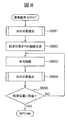
- 6 is a flowchart showing the operation of the map storage mode of the onboard processing device 120.
- 6 is a flowchart showing the operation of a position estimation mode of the onboard processing device 120.
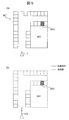
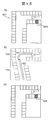
- FIG. 9A is a plan view showing an example of a parking lot 901
- FIG. 9B is a view visualizing a point cloud of landmarks stored in the RAM 122.
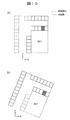
- Fig.10 (a) is a figure which shows an example which visualized point cloud data of point cloud map 124A
- FIG.10 (b) is a figure which shows an example which visualized point cloud data newly detected.
- the figure which shows the data which converted into a parking lot coordinate the point group which the vehicle 1 extracted by the sensor group in the position shown in FIG.
- FIG. 12 is a view showing a comparison between a point cloud map 124A and the local surrounding information 122B shown in FIG.
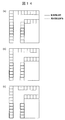
- 14 (a) to 14 (c) are diagrams showing the relationship with the point cloud map 124A when the local peripheral information 122B shown in FIG. 13 is moved by an integral multiple of the width of the parking frame.
- 15 (a) to 15 (c) are diagrams for explaining the matching method when an error occurs during turning.
- FIG. 1 is a block diagram of an automatic parking system 100 including an on-vehicle processing apparatus according to the present invention.
- the automatic parking system 100 is mounted on the vehicle 1.
- the automatic parking system 100 includes sensor groups 102 to 104 and 107 to 109, input / output device groups 110, 111 and 114, control device groups 130 to 133 for controlling the vehicle 1, and an on-vehicle processing device 120.
- the sensor group, the input / output device group, and the control device group are connected to the in-vehicle processing device 120 by signal lines, and exchange various data with the in-vehicle processing device 120.
- the on-vehicle processing device 120 includes an arithmetic unit 121, a RAM 122, a ROM 123, a storage unit 124, and an interface 125.
- the calculation unit 121 is a CPU.
- the calculation unit 121 may be configured to execute all or part of the calculation processing by another calculation processing device such as an FPGA.
- the RAM 122 is a readable and writable storage area, and operates as a main storage device of the on-vehicle processor 120.
- the RAM 122 stores an outlier list 122A described later and local peripheral information 122B described later.
- the ROM 123 is a read only storage area, and stores a program described later. This program is expanded by the RAM 122 and executed by the operation unit 121.
- the computing unit 121 operates as a point cloud acquiring unit 121A, a map generating unit 121B, a position estimating unit 121C, and a mode switching unit 121D by reading and executing a program.
- the storage unit 124 is a non-volatile storage device, and operates as an auxiliary storage device of the on-vehicle processing device 120.
- the storage unit 124 stores a point cloud map 124A.
- the point cloud map 124A is, for example, one or more parking lot data.
- the parking lot data is a set of position information of a certain parking lot, that is, latitude / longitude, coordinates indicating a parking area, and coordinates of points constituting a landmark present in the parking lot. The landmark will be described later.
- the interface 125 exchanges information with the in-vehicle processing device 120 and other devices constituting the automatic parking system 100.
- the sensor group includes a camera 102 for photographing the periphery of the vehicle 1, a sonar 103 or a radar 104 for observing the presence or absence of an object around the vehicle 1, a car navigation system 107, a vehicle speed sensor 108 and a steering angle sensor 109. .
- the camera 102 outputs an image obtained by capturing (hereinafter, a captured image) to the on-vehicle processing device 120.
- the on-vehicle processing device 120 performs positioning of a landmark described later using a captured image of the camera 102.
- the internal parameters such as the focal length of the camera 102 and the image pickup device size, and the external parameters such as the mounting position and mounting posture of the camera 102 on the vehicle 1 are known and stored in the ROM 123 in advance.
- the on-vehicle processor 120 can calculate the positional relationship between the subject and the camera 102 using the internal parameters and the external parameters stored in the ROM 123.
- the sonar 103 and the radar 104 each emit a sound wave or radio wave of a specific wavelength, and observe the position of the reflecting object by measuring the time until the reflected wave that is reflected from the object and received back is received.
- the sonar 103 and the radar 104 observe the position of the reflecting object as a point group and output it to the on-vehicle processing device 120.
- the car navigation system 107 includes a GPS receiver 107A and a storage unit 107B.
- the storage unit 107B is a non-volatile storage device, and stores the road map 107C.
- the road map 107C includes information on the road connection structure and the latitude and longitude corresponding to the road position.
- the car navigation system 107 collates the position information by the GPS receiver 107A with the corresponding road map 107C, and calculates the latitude and longitude of the road position where the vehicle is traveling (navigation self position).
- the accuracy of the latitude and longitude calculated by the car navigation system 107 may not be high, and may include, for example, an error of about several meters to 10 meters.
- the car navigation system 107 outputs the calculated latitude, longitude, and road identification number to the on-vehicle processor 120.
- the GPS receiver 107A receives signals from a plurality of satellites constituting the satellite navigation system, and calculates the position of the GPS receiver 107A, that is, the latitude and the longitude by calculation based on the received signals.
- the accuracy of the latitude and longitude calculated by the GPS receiver 107A may not be high, and may include, for example, an error of about several meters to 10 meters.
- the GPS receiver 107A outputs the calculated latitude and longitude to the car navigation system 107 or the on-vehicle processing device 120.
- the vehicle speed sensor 108 and the steering angle sensor 109 respectively measure the vehicle speed and the steering angle of the vehicle 1 and output them to the on-vehicle processor 120.
- the on-vehicle processing device 120 uses the outputs of the vehicle speed sensor 108 and the steering angle sensor 109 to calculate the movement amount and movement direction of the vehicle 1 by a known dead reckoning technique.
- the input device 110 includes a response button 110A and an automatic parking button 110B.
- the display device 111 is, for example, a liquid crystal display, on which information output from the on-vehicle processing device 120 is displayed.
- the input device 110 and the display device 111 may be integrated, for example, as a liquid crystal display corresponding to a touch operation. In this case, it may be determined that the response button 110A or the automatic parking button 110B has been pressed by touching a predetermined area of the liquid crystal display.
- the communication device 114 is used in order for devices outside the vehicle 1 and the on-vehicle processing device 120 to exchange information using wireless communication. For example, when the user is outside the vehicle 1, the user communicates with a portable terminal worn by the user to exchange information.
- the target with which the communication device 114 communicates is not limited to the portable terminal of the user.
- the vehicle control device 130 controls the steering device 131, the drive device 132, and the braking device 133 based on the operation command of the on-vehicle processing device 120.
- the steering device 131 operates the steering of the vehicle 1.
- the driving device 132 applies a driving force to the vehicle 1.
- the driving device 132 increases the driving force of the vehicle 1 by, for example, increasing the target rotation speed of the engine included in the vehicle 1.
- the braking device 133 applies a braking force to the vehicle 1.
- a landmark is an object having a feature that can be identified by a sensor, and is, for example, a parking frame line, which is one type of road surface paint, or a building wall that is an obstacle that hinders the traveling of a vehicle. In the present embodiment, vehicles and humans that are mobile objects are not included in the landmark.
- the on-vehicle processing device 120 detects landmarks existing around the vehicle 1, that is, points having identifiable features by sensors, based on information input from at least one of the camera 102, the sonar 103, and the radar 104. Do.
- detection of a landmark based on information input from an external sensor that is, information input from at least one of the camera 102, the sonar 103, and the radar 104 is referred to as "landmark positioning”.
- the on-vehicle processing device 120 detects a road surface paint such as a parking frame by operating an image recognition program as described below, for the image captured by the camera 102.
- a road surface paint such as a parking frame
- an edge is extracted from the input image by a Sobel filter or the like.
- a pair of rising of an edge, which is a change from white to black, and falling of an edge, which is a change from black to white is extracted.
- the distance between the pair substantially matches the first predetermined distance determined in advance, that is, the thickness of the white line forming the parking frame, the pair is set as a parking frame candidate.
- a plurality of parking frame candidates are detected by the same processing, and when the intervals between the parking frame candidates substantially coincide with a predetermined second predetermined distance, that is, the white line intervals of the parking frame, they are detected as the parking frame .
- the road surface paint other than the parking frame is detected by an image recognition program that executes the following processing.
- edges are extracted from the input image using a Sobel filter or the like. It is possible to detect by searching for a pixel whose edge strength is larger than a predetermined constant value and the distance between the edges is a predetermined distance corresponding to the width of the white line.
- the on-vehicle processing device 120 detects a vehicle or a human by, for example, known template matching and excludes it from the measurement result. Also, mobiles detected as follows may be excluded from the measurement results. That is, the on-vehicle processing device 120 calculates the positional relationship between the subject in the captured image and the camera 102 using the internal parameter and the external parameter. Next, the on-vehicle processing device 120 calculates the relative velocity between the vehicle 1 and the subject by tracking the subject in the captured images continuously acquired by the camera 102.
- the on-vehicle processing device 120 calculates the speed of the vehicle 1 using the outputs of the vehicle speed sensor 108 and the steering angle sensor 109, and determines that the subject is a moving body if it does not match the relative speed with the subject. , Exclude information on this mobile body from the measurement results.
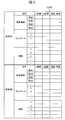
- FIG. 2 is a diagram showing an example of a point cloud map 124A stored in the storage unit 124. As shown in FIG. FIG. 2 shows an example in which two parking lot data are stored as the point cloud map 124A.
- Each parking lot data is composed of coordinates of a parking area, coordinates on a two-dimensional plane of points constituting a landmark, route coordinates traveled at the time of storage, and latitude and longitude corresponding to each coordinate.
- the coordinates of the parking area and the coordinates of the points constituting the landmark are coordinates in a coordinate system (first coordinate system) unique to the parking lot data.
- the coordinate system in parking lot data is called "parking lot coordinate system.”
- the coordinates of the vehicle 1 at the start of recording are the origin
- the traveling direction of the vehicle 1 at the start of recording is the Y axis
- the right direction of the vehicle 1 at the start of recording is the X axis.
- the coordinates of the parking area are recorded as the coordinates of four vertices of the rectangular area, for example, when the parking area is rectangular.
- the parking area is not limited to a rectangular shape, and may be a polygon other than a rectangular shape or an elliptical shape.
- Outlier list 122A In the outlier list 122A, information of points of the local surrounding information 122B which is not processed by the onboard processing device 120 is stored. The outlier list 122A is appropriately updated by the on-vehicle processing device 120 as described later.
- the local peripheral information 122 ⁇ / b> B stores the coordinates of points constituting a landmark detected by the on-vehicle processor 120 in the position estimation mode 203 described later. These coordinates are, for example, coordinates with the position as the origin, the traveling direction of the vehicle 1 as the Y axis, and the traveling direction right as the X axis, based on the position and attitude of the vehicle 1 when recording of the local peripheral information 122B is started. Coordinates in a system (second coordinate system). This coordinate system is hereinafter referred to as "local coordinate system".
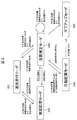
- FIG. 3 is a diagram for explaining the operation mode of the on-vehicle processor 120 and the transition conditions thereof. The operation described by this figure is equal to the operation of the mode switching unit 121D in the on-vehicle processing device 120.
- the on-vehicle processor 120 mainly has five operation modes, that is, a normal travel mode 201, a map storage mode 202, a position estimation mode 203, an automatic parking mode 204, and a give up mode 205.
- the on-vehicle processor 120 starts control of mode switching from the normal driving mode 201.
- the vehicle 1 is driven by the user. At this time, generation of a point cloud map or self-position estimation on the point cloud map is not performed, and only monitoring of a mode transition condition is performed.
- the mode transition is a comparison of the latitude / longitude (navi self position) of the self position obtained from the car navigation system 107 with the latitude / longitude near the point (registration point) where parking is desired to be registered beforehand.
- the mode transition is performed when the navigation self position enters within the 100 m range of the registration point.
- transition to the map storage mode 202 is made, and if a point cloud map near a point currently traveling is registered, transition is made to the position estimation mode 203 . It is determined from the latitude and longitude information corresponding to the landmark whether or not the nearby point cloud map is registered. The latitude longitude information of the self position and the latitude longitude information of the landmark are compared, and if there is a landmark within the predetermined distance, the map is registered, and if there is no landmark within the predetermined distance, the map is not Judge as registration.
- the vehicle 1 is driven by the user, and the on-vehicle processing device 120 is based on the information from the sensors provided in the vehicle 1, that is, parking lot data, that is, white line and obstacle information present in the parking lot and And collect information on travel routes.
- the on-vehicle processor 120 stores the collected information in the storage unit 124 as a point cloud map 124A.
- the latitude / longitude near the point (parked point) you want to park in advance is compared with the latitude / longitude information of the self position acquired from the car navigation system 107, and outside the fixed range centered on the registered point If the navigation self position is away from the registration point and the distance becomes 100 m or more, for example, the map storage mode 202 is transited to the normal travel mode 201. When the user enters a point group map registered section halfway, the map storage mode 202 is transitioned to the position estimation mode 203.
- the latitude / longitude information of the self position is compared with the latitude / longitude information of the landmark as to whether or not the own vehicle has entered the map registered section, and is predetermined based on the navigation self position. It is judged by whether or not there is a landmark (corresponding point group) within the distance. Then, if there is a landmark, it is determined that the vehicle has entered a section registered with the map.
- the vehicle 1 is driven by the user, and the on-vehicle processing device 120 collates the information from the sensors included in the vehicle 1 with the information of the point cloud map 124A to estimate the position of the vehicle in the point cloud map. .
- the on-vehicle processor 120 detects a white line or an obstacle present around the vehicle 1 based on the information from the sensor, and estimates the current position by collating with the point cloud map 124A.
- the latitude and longitude of the registration point is compared with the latitude and longitude information of the self position acquired from the car navigation system 107, and when the vehicle comes out from within a certain range centered on the registration point, for example When the navigation self position is away from the registration point and the distance becomes 100 m or more, the transition from the position estimation mode 203 to the normal travel mode 201 is made. When entering an unregistered section of the point group map from the middle, it is determined that there is no corresponding point group, and the transition from the position estimation mode 203 to the map storage mode 202 is made.
- the latitude / longitude information of the self position and the latitude / longitude information of the landmark are compared, and land within a predetermined distance centered on the self position. It is judged whether or not there is a mark (corresponding point group), and if there is no landmark, it is judged that the vehicle has entered an unregistered section of the point cloud map.
- automatic estimation from the position estimation mode 203 is performed only while the position estimation of the own vehicle is successful, and the self position is within a predetermined range from the parking position, and while the user is pressing the automatic parking button 110B.
- a transition to the parking mode 204 is made. That is, automatic control is performed based on the user's approval.
- transition to the give up mode 205 is made.
- the vehicle 1 is controlled by the on-vehicle processing device 120, and the self position in the point cloud map obtained in the position estimation mode 203 and the self position estimation result in the map continuously performed in the automatic parking mode 204 , The vehicle 1 is parked at the parking position stored in the point cloud map.
- the on-vehicle processor 120 continues to the position estimation mode 203 and detects white lines and obstacles existing around the vehicle 1 based on the information from the sensor and collates it with the point cloud map 124A. Estimate the current position. For mode transition, when the user releases the automatic parking button 110B, transition from the automatic parking mode 204 to the position estimation mode 203 is made. That is, automatic parking control is stopped. If the user's own position is lost in a state where the user presses the automatic parking button 110B, transition to the give up mode 205 is made.
- the mode transition when the user completes parking or is separated from the registration point by a predetermined distance, the mode transits to the normal driving mode 201.
- the map storage mode 202, the position estimation mode 203, and the automatic parking mode 204 will be described in detail below.
- Map memory mode 202 When a point cloud map is not recorded (no corresponding point group) within the predetermined range centered on the registration point, the on-vehicle processing device 120 transitions from the normal travel mode 201 to the map storage mode 202. For example, when the navigation self position falls within the range of 100 m centered on the registration point, and there is no corresponding point group, the map storage mode 202 is operated. While operating in the map storage mode 202, the screen of the display device 111 indicates that the map storage mode 202 is operating. Then, when the user moves to the parking position and then stops and operates the parking brake, the display device 111 is triggered by the activation of the parking brake, "Does the area around this traveling route be stored as a map?" The words are displayed.
- the map storage mode 202 is ended without storing the vicinity of the current travel route as a map.
- the operation of the map storage mode 202 by the on-vehicle processing device 120 is divided into two processes of extraction of a point group constituting a landmark and recording of the extracted point group.
- a process of extracting a point cloud by the on-vehicle processor 120 will be described.
- the on-vehicle processor 120 secures a temporary recording area in the RAM 122. Then, the on-vehicle processor 120 repeats the following processing until the map storage mode 202 ends or transitions to another mode. That is, the on-vehicle processing device 120 extracts a point group constituting a landmark based on at least one of a captured image of the camera 102 and observation information by the sonar 103 and the radar 104.
- the on-vehicle processing device 120 calculates, based on the outputs of the vehicle speed sensor 108 and the steering angle sensor 109, the movement amount and movement direction in which the vehicle 1 has moved from the previous shooting to the current shooting. Then, the on-vehicle processing device 120 records, in the RAM 122, a point group extracted based on the positional relationship with the vehicle 1, the movement amount and the movement direction of the vehicle 1. Furthermore, the on-vehicle processor 120 records the latitude and longitude output from the car navigation system 107 together with the point group. The on-vehicle processor 120 repeats this process.
- the position of the vehicle 1 and the coordinates of the point group are recorded as coordinate values of the recording coordinate system.
- the position of the vehicle 1 at the start of recording is taken as the origin (0, 0)
- the traveling direction (posture) of the vehicle 1 at the start of recording is the Y axis
- It is treated as a coordinate value of a coordinate system with the right direction as the X axis. Therefore, even if the point cloud is recorded in the same parking lot, the recording coordinate system set by the position and attitude of the vehicle 1 at the start of recording is different, so the point cloud constituting the landmark is recorded at different coordinates. Ru.
- the user parks the vehicle at the target parking position and applies the parking brake.
- the display device 111 displays the words "Do you want to store the area around this travel route as a map?".
- the response button 110A When the user presses the response button 110A, the map is stored.
- the on-vehicle processor 120 When the on-vehicle processor 120 is approved to store the map, the on-vehicle processor 120 records the current position on the RAM 122 as the parking position.
- the parking position is recorded, for example, as the coordinates of the four corners when the vehicle 1 is approximated to a rectangle.
- the on-vehicle processor 120 performs point cloud recording processing as follows.
- the on-vehicle processing device 120 determines whether or not the recorded coordinates of the parking lot, that is, the latitude and longitude substantially match the coordinates of any parking lot already recorded in the point cloud map 124A. If the two do not substantially match, the on-vehicle processor 120 records the point cloud information stored in the RAM 122 in the point cloud map 124A as new parking lot data. If the both substantially match, the on-vehicle processing device 120 determines whether to merge (integrate) the information of the point group where the coordinates of the parking lot substantially match as a point group of one parking lot.
- the on-vehicle processor 120 first performs coordinate conversion so that the parking position included in the parking lot data matches the parking position recorded in the RAM 122, and then the point cloud in the point cloud map 124A and the RAM 122 The degree of point cloud coincidence, which is the degree of coincidence with the stored point cloud, is calculated. Then, the on-vehicle processing device 120 determines that the calculated point cloud coincidence is merged if the calculated degree of point cloud coincidence is larger than the threshold, and determines not to merge if it is equal to or less than the threshold. The calculation of the degree of point cloud coincidence will be described later.
- the on-vehicle processing device 120 When it is determined that merging is not performed, the on-vehicle processing device 120 records the point cloud stored in the RAM 122 as new parking lot data in the point cloud map 124A. When it is determined that merging is performed, the on-vehicle processing device 120 adds the point cloud stored in the RAM 122 to the existing parking lot data of the point cloud map 124A.
- FIG. 4 is a flowchart showing the operation of the map storage mode 202 of the on-vehicle processor 120.
- the execution subject of each step described below is the computing unit 121 of the on-vehicle processor 120.
- the calculation unit 121 functions as the map generation unit 121B when performing the process shown in FIG.
- step S501 it is determined whether the map storage mode 202 has been entered. If it is determined that the map storage mode 202 has been entered, the process proceeds to step S501A. If the map storage mode 202 has not been entered, the process remains at step S501. In step S501A, a new recording area is secured in the RAM 122. In this storage area, the extracted point group and the current position of the vehicle 1 are recorded in the coordinates of the above-mentioned recording coordinate system.
- step S 502 information is acquired from the sensor group and the above-described landmark positioning, that is, extraction of a point group constituting a landmark using the photographed image of the camera 102, the sonar 103, and the radar 104 and output from the car navigation system 107 Link with the observed latitude and longitude values.
- step S 503 the moving amount of the vehicle 1 in the time from the sensing of the camera 102, the sonar 103 and the radar 104 to the latest sensing is estimated, and the current position of the vehicle 1 in the recording coordinate system recorded in the RAM 122 Update.
- the moving amount of the vehicle 1 can be estimated by a plurality of means.
- the moving amount of the vehicle 1 can be estimated from the change in the position of the object present on the road surface in the captured image of the camera 102. It may be estimated from the sensing results of the sonar 103 and the radar 104. When a high accuracy GPS receiver with a small error is mounted as the car navigation system 107, the output may be used. The movement amount of the vehicle 1 may be estimated from the vehicle speed sensor 108 and the steering angle sensor 109. Next, the process proceeds to step S504.
- step S504 the point group extracted in step S502 is stored in the RAM 122 as coordinates of the recording coordinate system based on the current position updated in step S503.
- step S505 it is determined whether or not the storage approval operation for pressing the response button 110A has been performed, and if it is determined that the storage approval operation has been performed, the process proceeds to step S505A, and it is determined that the storage approval operation is not performed. It returns to step S502.
- step S505A the current latitude and longitude of the vehicle 1 is acquired from the car navigation system 107, and the coordinates of the parking position, that is, the current position of the vehicle 1 and in the recording coordinate system of the four corners of the vehicle 1 are recorded.
- step S506 the current latitude and longitude of the vehicle 1 is acquired from the car navigation system 107, and the coordinates of the parking position, that is, the current position of the vehicle 1 and in the recording coordinate system of the four corners of the vehicle 1 are recorded.
- step S506 it is determined whether parking lot data having a latitude and longitude substantially matching the current latitude and longitude of the vehicle 1 acquired in step S505A is recorded in the point cloud map 124A. If it is determined that the current latitude and longitude of the vehicle 1 substantially matches the latitude and longitude of any of the parking lot data recorded in the point group map 124A, the process proceeds to step S507. Otherwise, the process proceeds to step S510.
- parking lot data of the point cloud map 124A in which it is determined that the current latitude and longitude of the vehicle 1 substantially coincide with each other will be referred to as target parking lot data.
- step S507 the recording coordinate system, which is the coordinate system of the point cloud data stored in the RAM 122, is converted to the coordinate system of the point cloud data of the target parking lot data based on the parking position. That is, the coordinate transformation formula of the recording coordinate system and the parking lot coordinate system is derived such that the parking position included in the target parking lot data coincides with the parking position recorded in step S505A. Then, by using this coordinate conversion formula, the coordinates of the points constituting the landmark stored in the recording coordinate system in the RAM 122 are converted into the parking lot coordinate system of the target parking lot data.
- a point cloud coincidence rate IB between the point cloud data stored in the RAM 122 and the target parking lot data is calculated.
- Equation 1 is the number of points within which the distance between each point of the point cloud data subjected to the coordinate conversion in step S507 and each point of the target parking lot data is within a predetermined distance.
- Equation 1 “D1” is the number of points in the point cloud data stored in the RAM 122, and “D2” is the number of points in the point cloud data of the target parking lot data.
- step S508 it is determined whether the point cloud matching rate IB calculated in step S507A is larger than a predetermined threshold. If it is determined that the point cloud coincidence rate IB is larger than the threshold, the process proceeds to step S509. If it is determined that the point cloud coincidence rate IB is equal to or less than the threshold, the process proceeds to step S510.
- step S509 the point cloud data subjected to coordinate conversion in step S507 is added to the merging process, that is, the target parking lot data of the point cloud map 124A stored in the storage unit 124.
- step S510 which is executed when a negative determination is made in step S506 or step S508, the point cloud data stored in the RAM 122, the latitude and longitude of the vehicle 1 recorded in step S505A, and the parking position are used as new parking lot data.
- the group map 124A is recorded. This is the end of the flowchart of FIG.
- Position estimation mode 203 When it is determined that the user drives the vehicle 1 to move to the vicinity of the registration point, and it is determined that the peripheral point cloud map is stored, the transition from the normal travel mode 201 to the position estimation mode 203 is made. For example, when the navigation self position falls within the range of 100 m centered on the registration point and there is a corresponding point group, the position estimation mode 203 is operated. The operation of the on-vehicle processor 120 at this time will be described below with reference to a flowchart.
- FIG. 5 is a flowchart showing the operation of the position estimation mode of the on-vehicle processor 120.
- the execution subject of each step described below is the computing unit 121 of the on-vehicle processor 120.
- the on-vehicle processor 120 specifies a point cloud (parking spot point group) having a latitude and longitude substantially matching the current position of the vehicle 1 among the plurality of parking lot data included in the point cloud map 124A (step S601).
- the on-vehicle processing device 120 performs initialization of the local surrounding information 122B stored in the RAM 122 as initialization processing, and initialization of the current position of the vehicle 1 stored in the RAM 122 (step S601A). Specifically, if conventional information is recorded, it is erased and a new coordinate system is set. In this embodiment, this coordinate system is called a local coordinate system. This local coordinate system is set based on the position and attitude of the vehicle 1 when step S601A is performed.
- the position of the vehicle 1 when step S601A is performed is set to the origin of the local coordinate system, and the X axis and the Y axis are set according to the direction when step S601A is performed. Further, in the initialization of the current position of the vehicle 1, the current position of the vehicle 1 is set to the origin (0, 0).
- step S603 it is determined whether the self position can be estimated. If it is determined that the estimation has been completed, the processing proceeds to step S604. If it is determined that the estimation can not be performed, the processing returns to step S602.
- step S604 the on-vehicle processing device 120 displays the self position estimation result on the map on the display device 111, and in the subsequent step S605, determines whether or not the self position falls within a predetermined range from the storage parking position. . For example, when the vehicle 1 approaches the storage parking position to the distance Nm, it is determined that the vehicle 1 is within the predetermined range. If it is determined that it is within the predetermined range, the process proceeds to step S606, and if it is determined that it is not within the predetermined range, that is, it is determined that it is out of range, the process returns to step 604.
- step S606 the on-vehicle processing device 120 displays that automatic parking is possible on the display device 111, and in the subsequent step S607, it is determined whether or not the automatic parking button 110B has been pressed by the user. If it is determined that the automatic parking button 110B has been pressed, the process proceeds to step S608 to shift to the automatic parking mode, and the automatic parking process is executed according to the procedure shown in FIG. The process returns to step S606.
- the computing unit 121 functions as a local peripheral information creating unit when performing the processing shown in steps S621 to S623 of FIG. 6A.
- step S621 The landmark positioning in step S621, the movement estimation of the vehicle in step S622, and the update of the local surrounding information 122B in step S623 are substantially the same as the processing in steps S502 to S504 in FIG. The difference is that the data stored in the RAM 122 is recorded as the local peripheral information 122B.
- step S623A the on-vehicle processor 120 selects local surrounding information whose details are shown in FIG. 6B (step S623A).
- the selection processing of the local peripheral information is processing for selecting a point to be used in the matching processing in step S624 described later, from the point group obtained as the local peripheral information.
- the point cloud obtained from the local peripheral information may not be matched with the point cloud map because the overall shape thereof is different due to the accumulated error of the movement estimation of the vehicle.
- this local peripheral information selection processing a point group in a range in which the shape error is small and which can be matched is adaptively selected.
- step S624 the on-vehicle processing device 120 performs a matching process whose details are shown in FIG. 7 (step S624).
- this matching process the correspondence relationship between the parking space coordinate system and the local coordinate system, that is, the coordinate conversion equation between the parking space coordinate system and the local coordinate system is obtained.
- step S625 the on-vehicle processing device 120 uses the coordinates of the vehicle 1 in the local coordinate system updated in step S622 and the coordinate conversion equation obtained in step S625 to calculate the coordinates of the vehicle 1 in the parking lot coordinate system, Calculate the position.
- step S626 the process proceeds to step S626.
- step S626 the on-vehicle processor 120 executes a self-diagnosis to determine the reliability of the position calculated in step S625.
- Self-diagnosis is judged using, for example, the following three indicators.
- the first index compares the amount of movement of the vehicle 1 estimated by the known dead reckoning technique using the outputs of the vehicle speed sensor 108 and the steering angle sensor 109 with the amount of movement in a predetermined period estimated by self position estimation, If the difference is larger than a predetermined threshold value, it is determined that the reliability is low.
- the second index is determined by the amount of error of the corresponding point calculated at the time of matching. If the amount of error is larger than a predetermined threshold value, it is determined that the reliability is low.
- the third indicator it is determined whether there is a similar solution.
- a similar solution for example, by translating the obtained solution by the width of the parking frame, it is determined that the reliability is low when there are the same number of points whose corresponding point errors are within a certain range. It is determined that the self-position can be estimated if it is not determined that the reliability is low in all of these three indicators.
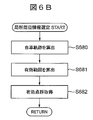
- the calculation unit 121 functions as a local peripheral information selection unit when performing the process shown in FIG. 6B.
- step S680 the trajectory to the current position of the vehicle is calculated using the vehicle movement amount calculation implemented in step S622.
- the locus generated by interpolating the coordinate points of the host vehicle position calculated from the host vehicle movement amount is the host vehicle locus.
- step S 681 for the point group of local peripheral information, a shape error is small, and a matching effective range is calculated.
- This effective range is determined from the length and shape of the vehicle trajectory calculated in step S680.
- an estimation error of the moving amount easily occurs. Conversely, if there are too few point clouds, matching will be difficult. Therefore, a point cloud in a range in which the minimum distance D [m] determined in advance from the current position is traced back along the trajectory is acquired.
- a point group in a range X [m] ⁇ Y [m] predetermined in advance with the locus at the center is set as an effective range of the point group of the local peripheral information. That is, the effective range has a shape along the obtained trajectory.
- step S682 a point within the effective range obtained in step S681 is acquired as a point cloud of local peripheral information.
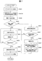
- the calculation unit 121 functions as a position estimation unit 121C when performing the process shown in FIG. 6A.
- step S641 the outlier list 122A stored in the RAM 122 is applied to the local peripheral information 122B to temporarily exclude the points described in the outlier list 122A among the point clouds included in the local peripheral information 122B.
- This application range is steps S642 to S653.
- step S654 points that were previously included in the outlier list 122A are also included.
- the steps S641 to S643 can not be executed at the first execution of the flowchart shown in FIG. 7, the execution is started from the step S650. Next, the process proceeds to step S641A.
- step S641A the coordinates of the point cloud detected from the latest captured image, that is, the point cloud constituting the landmark detected in step S621 of FIG. 6A, are converted into coordinates of the parking lot coordinate system. This conversion is realized by using the position of the vehicle 1 in the local coordinate system updated in step S 622 and the coordinate conversion formula from the local coordinate system calculated previously to the parking space coordinate system.
- the degree of instantaneous coincidence IC is calculated.
- step S643 it is determined whether the degree of instantaneous coincidence IC calculated in step S642 is larger than a threshold. If it is determined that the momentary coincidence degree IC is larger than the threshold value, the process proceeds to step S650. If it is determined that the momentary coincidence degree IC is equal to or less than the threshold value, the process proceeds to step S644.
- step S644 periodic features, for example, a plurality of parking frames arranged in a row, are detected from the target parking lot data of the point cloud map 124A, that is, the point cloud data.
- the parking frame line can be detected from the points arranged at intervals equivalent to the thickness of the white line.
- step S645 it is determined whether or not the periodic feature is detected in step S644. If it is determined that it has been detected, the process proceeds to step S646, and if it is determined that it has not been detected, the process proceeds to step S650.
- step S646 the period of the periodic feature, for example, the width of the parking frame is calculated. The width of the parking frame referred to here is the interval between white lines constituting the parking frame.
- step S647 the period of the periodic feature, for example, the width of the parking frame is calculated. The width of the parking frame referred to here is the interval between white lines constituting the parking frame.
- step S 647 based on the coordinate conversion formula calculated in the previous step S 653, the coordinate conversion formula is changed in a plurality of ways to calculate the overall matching degree IW.
- the coordinate transformation equation is changed in multiple ways so as to be shifted by an integral multiple of the periodic feature detected by the point cloud map.
- Equation 3 “DWin” is the distance to the point constituting the closest point cloud map 124A among the points obtained by converting the points constituting the local peripheral information 122B into the parking lot coordinate system using the above-mentioned coordinate conversion formula Is the number of points below the predetermined threshold. Further, in Equation 3, “DWall” is the number of points detected in step S621. Next, the process proceeds to step S648.
- step S648 a coordinate conversion equation giving the largest overall coincidence IW among the plurality of overall coincidences IW calculated in step S647 is stored in the RAM 122, and the flow proceeds to step S650.
- the matching process in step S650, the error minimizing process in step S651, and the convergence determination process in step S625 can use an ICP (Iterative Closest Point) algorithm, which is a known point cloud matching technique.
- ICP Intelligent Closest Point
- step S650 is executed.
- the correspondence between the point group included in the parking lot data and the point group included in the local peripheral information 122B is calculated.
- step S643 or step S648 the point cloud data of the local peripheral information 122B uses a value subjected to coordinate conversion using the coordinate conversion equation stored in the RAM 122.
- step S643 when an affirmative determination is made in step S643 and step S650 is executed, the coordinate conversion formula calculated in step S653 executed last time is used. On the other hand, when step S650 is executed following step S648, the coordinate conversion equation stored in step S648 is used. Next, the process proceeds to step S651.
- step S651 the coordinate conversion equation is changed such that the error of the corresponding point is minimized.
- the coordinate conversion equation is changed such that the sum of the indices of the distances between the points associated in step S650 is minimized.
- the sum of absolute values of distances can be adopted as the sum of indices of distances between associated points.
- step S652 it is determined whether the error has converged. If it is determined that the error has converged, the process proceeds to step S653. If it is determined that the error has not converged, the process returns to step S650. In the subsequent step S653, the coordinate conversion equation changed in step S651 is finally stored in the RAM 122, and the process proceeds to step S654.
- step S654 the outlier list 122A is updated as follows. First, the existing outlier list 122A stored in the RAM 122 is cleared. Next, the point group of the local peripheral information 122B is converted to the parking lot coordinate system using the coordinate conversion formula recorded in step 653, and each point constituting the local peripheral information 122B and the point cloud map 124A corresponding to that point Calculate the distance to the point to be configured, that is, the Euclidean distance. Then, if the calculated distance is longer than the predetermined distance, the point of the local peripheral information 122B is added to the outlier list 122A. However, at this time, spatial end positions may be added as a further condition to be added to the outlier list 122A. The spatial end is a point at which the distance to another point is long, such as a point acquired when recording is started. The outlier list 122A is updated by the above processing. This is the end of the flowchart of FIG.
- Automatic parking from self position estimation mode 203 only while the position estimation of the host vehicle is successful, and the self position is within a predetermined range from the parking position, and while the user is pressing the automatic parking button 110B.
- a transition to mode 204 is made. That is, automatic control is performed based on the user's approval.
- step S661 the position of the vehicle 1 in the parking lot coordinate system is estimated.
- the processing in this step is the same as step S604 in FIG.
- step S662 a travel route from the position estimated in step S661 to the parking position stored in the point cloud map 124A is generated by a known route generation method.
- step S663 the process proceeds to step S663.
- step S663 the steering device 131, the drive device 132, and the braking device 133 are controlled via the vehicle control device 130, and the vehicle 1 is moved to the parking position along the route generated in step S662. Only when the automatic parking button 110B is kept pressed by the user, an operation command is output to the driving device 132. Further, when a person or a moving vehicle is extracted from the photographed image of the camera 102, the sonar 103 and the radar 104, the braking device 133 is operated to stop the vehicle 1. In the subsequent step S664, the position of the vehicle 1 is estimated as in step S661.
- step S665 it is determined whether the parking is completed, ie, whether or not the vehicle 1 has reached the parking position, and if it is determined that the parking is not completed, the process returns to step S663 to determine that the parking is completed. If so, the flowchart of FIG. 8 is ended.
- FIG. 9A is a plan view showing an example of the parking lot 901.
- a parking lot 901 is provided around the building 902. There is only one entrance of the parking lot 901 at the lower left of the figure.
- a square shown in FIG. 9A represents a parking frame which is road surface paint, and a hatched parking frame 903 is a parking area of the vehicle 1 (an area which becomes a parking position when parking is completed).
- the landmark is described as only the parking frame line.
- the vehicle 1 is indicated by a triangle, and the acute angle of the triangle indicates the traveling direction of the vehicle 1.
- Map memory mode 202 Part 1 When transiting from the normal driving mode 201 to the map storage mode 202 near the entrance of the parking lot 901, the on-vehicle processor 120 starts landmark positioning, and records the coordinates of the points constituting the parking frame line (step S501 in FIG. 4). : YES, S502 to S504). Then, the vehicle 1 repeats the processing of steps S502 to S504 of FIG. 4 until the response button 110A is pressed and the storage processing is approved.
- FIG. 9B is a diagram visualizing a point group of landmarks stored in the RAM 122.
- a solid line indicates a point cloud of landmarks stored in the RAM 122
- a broken line indicates landmarks not stored in the RAM 122. Since the camera 102, the sonar 103, and the radar 104 of the vehicle 1 have a limited sensing range, the vicinity of the entrance of the parking lot 901 when the vehicle 1 is near the entrance of the parking lot 901 as shown in FIG. Only the parking line is recorded. When the user moves the vehicle 1 to the back of the parking lot 901, the on-vehicle processor 120 can record the point cloud of the entire landmark of the parking lot 901.
- the on-vehicle processing device 120 acquires the latitude and longitude of the vehicle 1 from the car navigation system 107 and The coordinates of are recorded (step S505: YES, S505A).
- step S506 NO
- point cloud data shown in FIG. 10A is recorded as parking lot data of point cloud map 124A and point cloud data shown in FIG. 10B is newly obtained will be described.
- the point cloud data shown in FIG. 10A is, for example, point cloud data obtained when traveling from the entrance of the parking lot 901 shown in FIG. 9A to the right and reaching the parking position.
- the vehicle 1 is shown in FIG. Since the vehicle has traveled to the right compared to (a), the point cloud data of the parking frame indicated by the broken line in FIG. 10A is not acquired.
- the point cloud data shown in FIG. 10B is, for example, point cloud data obtained when traveling from the entrance of the parking lot 901 to the left and reaching the parking position. Since the vehicle has traveled to the left compared to FIG. 9A, the point cloud data of the parking frame indicated by the broken line in FIG. 10B is not acquired.
- the parking lot 901 is inclined as compared to FIG. 10 (a) because the vehicle 1 does not face the parking lot 901 when transitioning to the storage mode. It is recorded in.
- step S506 when the user approves the storage with the response button 110A, it is determined that the latitude and longitude substantially matching the current latitude and longitude of the vehicle 1 are recorded in the point cloud map 124A (S506: YES) Coordinate conversion is performed on the basis of the parking positions shown in FIGS. 10A and 10B, that is, the parking frame 903 (step S507). Then, point cloud coincidence rate IB is calculated (step S507A), and if it is determined that point cloud coincidence rate IB is larger than a predetermined threshold (step S508: YES), merge processing is performed, as shown in FIG. The point cloud data shown in FIG. 10B is integrated with the point cloud data (step S509). By this integration, the point cloud of the parking frame line on the left side of the illustration not recorded in FIG. 10A is newly recorded, and the parking frame line on the right side or the upper part of the illustration already recorded is configured. The density of the group is increased.
- FIG. 11 is a diagram showing the current position of the vehicle 1 in the parking lot 901 shown in FIG. 9 (a).
- the vehicle 1 is directed upward in the figure. 12 to 13 show parking frame lines of a portion surrounded by a broken line circle in FIG. 10 which is a front area of the vehicle 1.
- FIG. 12 is a diagram showing data obtained by converting the point group sensed and extracted by the sensor group at the position shown in FIG. 11 into parking lot coordinates. That is, the point group shown in FIG. 12 is a point group detected from the latest captured image in the local peripheral information 122B, and is data processed in step S641A in FIG. However, in FIG. 12, they are not dotted but represented as broken lines. Further, in FIG. 12, the vehicle 1 is also displayed for comparison with FIG. 11. As shown in FIG. 12, point cloud data of the parking frame line continuously exists on the left side of the vehicle 1, and point cloud data of the parking frame line exists only on the front side of the vehicle 1 on the right side.
- FIG. 13 is a diagram showing a comparison between the point cloud map 124A and the local surrounding information 122B shown in FIG. 11 when the estimation of the position of the vehicle 1 in the parking lot coordinate system includes an error.
- the local peripheral information 122B present on the right side of the vehicle 1 is offset from the point cloud map 124A.
- the momentary coincidence IC is calculated in such a state (step S642 in FIG. 7), the momentary coincidence IC has a low value due to the above-mentioned deviation on the right side of the vehicle 1.
- step S643 NO
- the parking frame is detected as a periodic feature (steps S644, S645: YES), and the width (period) of the parking frame is obtained from the point cloud map 124A. Is calculated (step S646) and moved by an integral multiple of the width of the parking frame to calculate the overall matching score IW (step S647).
- FIGS. 14 (a) to 14 (c) are diagrams showing the relationship with the point cloud map 124A when the local peripheral information 122B shown in FIG. 13 is moved by an integral multiple of the width of the parking frame.
- the local peripheral information 122B shown in FIG. 14 is moved upward by +1, 0 and -1 times the width of the parking frame.
- the local peripheral information 122B is moved upward by one of the width of the parking frame, and the gap between the local peripheral information 122B and the point cloud map 124A is enlarged. Therefore, the overall matching score IW in FIG. 14A is smaller than that in the case of not moving.
- FIG. 14B the local peripheral information 122B is not moved, and as seen in FIG.
- the local peripheral information 122B and the point cloud map 124A are shifted by one width of the parking frame.
- the local peripheral information 122B is moved downward by one of the width of the parking frame, and the local peripheral information 122B substantially matches the point cloud map 124A. Therefore, the overall matching score IW in FIG. 14C is larger than that in the case of not moving.
- the overall match degree IW corresponding to FIG. 14C is determined to be the maximum in the example shown in FIG.
- the coordinate conversion equation to be stored is stored in the RAM 122 (step S648).
- the on-vehicle processor 120 improves the position accuracy to be estimated.
- FIG. 15 is a diagram showing a comparison between the point cloud map 124A and the local surrounding information 122B shown in FIG. 11 when the estimation of the position of the vehicle 1 in the parking lot coordinate system includes an error.
- FIG. 15 (a) shows the current position of the vehicle 1 in the parking lot 901 shown in FIG. 9 (a).
- the vehicle 1 is directed to the right in the figure.
- FIG.15 (b) is a figure which shows the data which converted into the parking lot coordinate the point cloud extracted from the image image
- the traveling locus has an effective portion 151 and an invalid portion 152, and the point cloud of the local peripheral information is divided into an effective range 153 and an ineffective range 154.
- FIG. 15C shows the result of matching using the point group in the effective range 153.
- the point group in a predetermined range centering on the effective portion 151 of the vehicle trajectory is set as the effective range 153 of the point group of the local peripheral information by the process of step S681 in FIG. 6B.
- the effective part 151 of the traveling locus ends at a part where the traveling locus is traced back from the self position in the reverse direction and is largely turned.
- a point (point within the effective range) falling within a predetermined range centering on the effective portion 151 of the traveling locus is acquired as a point cloud of local peripheral information and used for matching.
- a point (point within the ineffective range 154) that falls within a predetermined range around the ineffective portion 152 of the travel locus is not used for matching. Therefore, correct matching can be performed.
- the in-vehicle processing device 120 stores the point cloud data (point cloud map 124A) including a plurality of coordinates in the first coordinate system (parking lot coordinate system) of points representing a part of the object, and A sensor input unit (interface 125) for acquiring an output of the camera 102 for acquiring information around the vehicle 1, a movement information acquisition unit (interface 125) for acquiring information on movement of the vehicle 1, a sensor input unit, Based on the information acquired by the movement information acquisition unit, a local periphery including a plurality of coordinates in the second coordinate system (local coordinate system) of the position of the vehicle in the second coordinate system (local coordinate system) and a part representing an object The relationship between the first coordinate system and the second coordinate system is estimated based on the local peripheral information creation unit that generates the information 122B, the point cloud map 124A and the local peripheral information 122B, and the car in the first coordinate system is And a position estimation unit 121C for estimating
- the on-vehicle processing device 120 estimates coordinate transformation formulas of the parking lot coordinate system and the local coordinate system based on the point cloud map 124A and the local peripheral information 122B, and estimates the position of the vehicle 1 in the parking lot coordinate system.
- the point cloud map 124A is information stored in advance in the storage unit 124, and the local surrounding information 122B is generated from the outputs of the camera 102, the vehicle speed sensor 108, and the steering angle sensor 109. That is, the on-vehicle processing device 120 acquires information of point groups in a coordinate system different from the recorded point group coordinate system, and the position of the vehicle 1 in the recorded coordinate system based on the correspondence between different coordinate systems. Can be estimated.
- the on-vehicle processing device 120 estimates coordinate transformation formulas of the parking lot coordinate system and the local coordinate system based on the point cloud map 124A and the local peripheral information 122B, noise is generated in part of point cloud data of the local peripheral information 122B. It is hard to be affected even if it is included. That is, the position estimation of the vehicle 1 by the on-vehicle processing device 120 is resistant to disturbances.
- the position estimation unit 121C searches for points corresponding to each point constituting the local peripheral information 122B from the point cloud data (step S650 in FIG. 7), and the distance between the corresponding points is minimized. As described above, coordinate transformation formulas of the first coordinate system and the second coordinate system are estimated (step S651 in FIG. 7).
- the position estimation unit 121C excludes point data of local peripheral information that is longer than a predetermined threshold, and the point constituting the point cloud data or the local peripheral information 122B and the distance to the point corresponding to this point In other words, the outlier list 122A is applied (steps S641 and S653 in FIG. 7) to perform search and estimation. Therefore, since the point group data whose distance which can be regarded as a noise component is separated is excluded from the calculation target, the accuracy of the coordinate conversion equation can be improved.
- Point cloud data and points included in local peripheral information are represented as coordinates in a two-dimensional space.
- the position estimation unit 121C performs the search and estimation excluding the point at which the distance between corresponding points is longer than a predetermined threshold and spatially located at the end of the local peripheral information 122B.
- the point cloud stored in the parking lot data of the point cloud map 124A relates to a landmark closer to the parking position than the point at which the user pressed the recording start button 110A.
- local peripheral information 122B includes a point which does not correspond to any point stored in the parking lot data. If ICP is processed including steps such as these, that is, steps S650 to S652 in FIG. 7, an appropriate solution can not be obtained. Therefore, by eliminating these, it is possible to obtain an appropriate solution.
- Point cloud data includes periodic features.
- the position estimation unit 121C estimates the coordinate conversion formula between the first coordinate system and the second coordinate system, and then reduces the distance between the corresponding points based on the distance of one period of the periodic feature so that the distance between the corresponding points becomes short.
- the coordinate conversion equation between the one coordinate system and the second coordinate system is corrected (steps S646 to S648 in FIG. 7).
- step S641A the processing of steps S 644 to S 648 in FIG. 7 is not performed constantly, but is performed only when it is determined necessary in consideration of the necessity of the processing.
- the on-vehicle processing device 120 has coordinates in the third coordinate system (recording coordinate system) of points representing a part of the object excluding the moving object based on the information acquired by the sensor input unit and the movement information acquisition unit.
- the point cloud acquisition unit 121A is configured to create a plurality of pieces of second point cloud data and store the second point cloud data as the point cloud map 124A in the storage unit 124. Therefore, the on-vehicle processor 120 can create the point cloud map 124A when the vehicle 1 equipped with the on-vehicle processor 120 travels.
- the creation process of the point cloud map 124A and the position estimation process of the vehicle 1 are common in terms of landmark positioning, and program modules can be used in common.
- the third coordinate system (recording coordinate system) is set based on the position and attitude of the vehicle when the creation of the second point group data is started.
- the point cloud acquisition unit 121A determines the parking position of the vehicle 1
- a plurality of second point group data are integrated by estimating the relationship between different coordinate systems as a reference (steps S507 and S509 in FIG. 4). Therefore, even if different recording coordinate systems are set each time point cloud data is acquired, a plurality of point cloud data can be integrated. This focuses on the point at which the vehicle 1 is parked at the same parking position although the position at which acquisition of point cloud data is started and the attitude of the vehicle 1 at that time are various.
- the on-vehicle processing device 120 drives the vehicle based on the output of the position estimation unit 121C and moves the vehicle to a parking position designated in advance in the first coordinate system, and information on the position of the vehicle 1
- the points constituting the point cloud map 124A are points representing a part of the composition of the parking lot.
- the storage unit 124 also stores the latitude and longitude of a parking lot consisting of a stationary object of point cloud data.
- the on-vehicle processing device 120 includes the car navigation system 107 and a sensor group for sensing a point cloud around the camera 102, the sonar 103, and the radar 104.
- the map generation unit 121B the points as shown in FIG.
- a point cloud map 124A of a data format in which groups and latitude / longitude information are linked is generated.
- the latitude and longitude information it is possible to determine the presence or absence of surrounding point clouds and the relationship with the road map, and to automatically transition to the storage mode and the position estimation mode. Therefore, the user does not have to perform an operation for mode transition, and it is possible to smoothly shift while traveling to storage and automatic parking.
- the first embodiment described above may be modified as follows.
- the on-vehicle processor 120 may be connected to a plurality of cameras.
- the on-vehicle processing device 120 can extract point clouds from a wide range of landmarks existing around the vehicle 1 by using captured images of a plurality of cameras.
- the on-vehicle processing device 120 may not receive the sensing result from the vehicle speed sensor 108 and the steering angle sensor 109. In this case, the on-vehicle processing device 120 estimates the movement of the vehicle 1 using the captured image of the camera 102. The on-vehicle processor 120 calculates the positional relationship between the subject and the camera 102 using the internal parameters and the external parameters stored in the ROM 123. The movement amount and movement direction of the vehicle 1 are estimated by tracking the subject in a plurality of photographed images.
- Point cloud information such as the point cloud map 124A and the local surrounding information 122B may be stored as three-dimensional information. Similar to the first embodiment, the three-dimensional point group information may be compared with another point group in two dimensions by projecting on a two-dimensional plane, or may be compared in three dimensions. .
- the on-vehicle processing device 120 can obtain a three-dimensional point group of landmarks as follows. That is, a known motion stereo technique or its motion estimation portion is calculated using the movement amount of the vehicle 1 calculated based on the outputs of the vehicle speed sensor 108 and the steering angle sensor 109 and the plurality of photographed images output by the camera 102. By using the information corrected by the field sensor or the positioning sensor, it is possible to obtain a three-dimensional point group of a stationary three-dimensional object.
- the on-vehicle processing device 120 may proceed to step S644 if the determination in step S643 of FIG. 7 is not negative and proceeds to step S644 but is determined several times consecutively.
- the on-vehicle processing device 120 determines whether or not the percentage of points determined to be outliers in the local surrounding information 122B is larger than a predetermined threshold instead of the determination in step S643 of FIG. It is also good. If the ratio is larger than the threshold, the process proceeds to step S644. If the ratio is smaller than the threshold, the process proceeds to step S650. Further, in addition to the determination in step S643 of FIG. 7, the on-vehicle processing device 120 may proceed to step S644 only when the above ratio is large.
- the on-vehicle processing device 120 may perform the processes of steps S644 and S646 in FIG. 7 in advance. Furthermore, the processing result may be recorded in the storage unit 124.
- the on-vehicle processing device 120 may receive the operation command from the user not only from the input device 110 provided inside the vehicle 1, but also from the communication device 114. For example, when the communication device 114 communicates with a portable terminal owned by the user and the user operates the portable terminal, the on-vehicle processing device 120 may perform the same operation as when the automatic parking button 110B is pressed. In this case, the on-vehicle processing device 120 can perform automatic parking not only when the user is inside the vehicle 1 but also after the user gets off.
- the on-vehicle processing device 120 may park not only at the parking position recorded in the point cloud map 124A, but also at a position designated by the user.
- the designation of the parking position by the user is performed, for example, by the on-vehicle processing device 120 displaying a candidate for the parking position on the display device 111 and the user selecting one of them using the input device 110.
- the on-vehicle processing device 120 may receive the point cloud map 124A from the outside via the communication device 114, or may transmit the created point cloud map 124A to the outside via the communication device 114. Good. Moreover, the other party which the vehicle-mounted processing device 120 transmits / receives the point cloud map 124A may be another vehicle-mounted processing device 120 mounted on another vehicle, or a device managed by an organization managing a parking lot.
- the automatic parking system 100 may include a portable terminal in place of the car navigation system 107, and may record identification information of a base station with which the portable terminal communicates, instead of the latitude and longitude. Since the communication range of the base station is limited to about several hundred meters, the possibility of the same parking lot is high if the base stations performing communication are the same.
- the periodic feature included in the parking lot data is not limited to the parking frame.
- a plurality of straight lines constituting a pedestrian crossing which is one of the road surface paints, is also a periodic feature.
- the parking lot data is composed of information of obstacles such as a wall acquired by a laser radar or the like, regularly arranged pillars are also a periodic feature.
- vehicles and people that are mobile objects are not included in the landmarks, but mobile objects may be included in the landmarks.
- landmarks which are mobiles and landmarks other than mobiles may be stored so as to be distinguishable.
- the on-vehicle processing device 120 may identify the detected landmarks in the recording mode, and record the identification results of the respective landmarks together with the point cloud map 124A.
- shape information and color information of landmarks obtained from a captured image, and three-dimensional shape information of landmarks by known motion stereo technology are used.
- the landmark is identified as, for example, a parking frame, a road surface paint other than the parking frame, a curb, a guardrail, a wall, and the like.
- the on-vehicle processing device 120 may include a vehicle or a human being as a moving object in a landmark, and record the identification result in the point cloud map 124A in the same manner as other landmarks. In this case, the vehicle and the human may be combined and identified and recorded as a "mobile", or the vehicle and the human may be individually identified and recorded.
- the present invention is not limited to the above-mentioned embodiment, and various designs are possible in the range which does not deviate from the spirit of the present invention described in the claim. It is possible to make changes.
- the above-described embodiment has been described in detail in order to explain the present invention in an easy-to-understand manner, and is not necessarily limited to one having all the described configurations.
- part of the configuration of one embodiment can be replaced with the configuration of another embodiment, and the configuration of another embodiment can be added to the configuration of one embodiment.
Landscapes
- Engineering & Computer Science (AREA)
- Automation & Control Theory (AREA)
- Mechanical Engineering (AREA)
- Transportation (AREA)
- Physics & Mathematics (AREA)
- General Physics & Mathematics (AREA)
- Remote Sensing (AREA)
- Radar, Positioning & Navigation (AREA)
- Human Computer Interaction (AREA)
- Aviation & Aerospace Engineering (AREA)
- Chemical & Material Sciences (AREA)
- Combustion & Propulsion (AREA)
- Navigation (AREA)
- Traffic Control Systems (AREA)
- Control Of Driving Devices And Active Controlling Of Vehicle (AREA)
- Image Analysis (AREA)
- Image Processing (AREA)
Abstract
本発明の課題は、モードの選択を自動で行う車載処理装置を得ることである。本発明の車載処理装置120は、予め設定された登録地点に車両1が接近しかつ車両の周囲の点群データが記憶部124に格納されていない場合に点群データを取得して記憶部に記憶する地図記憶モード202と、登録地点に車両が接近しかつ車両の周囲の点群データが記憶部に格納されている場合に位置推定部121Cにより車両の位置を推定する位置推定モード203とを、車両の緯度経度の測位情報に基づいて遷移させるモード切り替え部121Dを備える。
Description
本発明は、車載処理装置に関する。
車両の挙動を制御して所定の駐車位置まで自動走行する自動駐車装置や駐車支援装置が提案されている。
特許文献1には、過去に運転者が前記車両を前記駐車位置へと駐車させた際に前記車両に搭載された撮像手段により撮像された車両周囲の画像内の代表ポイントの軌跡を、そのときの運転者による運転操作に関する情報と対応付けて記憶する記憶手段と、前記駐車位置への誘導を行う際に、前記撮像手段により撮像される車両周囲の画像内の代表ポイントを検出し、検出した現在の代表ポイントが、前記記憶手段に記憶されている過去の代表ポイントの軌跡上に沿うように、前記車両の挙動を制御する制御手段を備えることを特徴とする駐車支援装置が開示されている。
特許文献1においては、「記憶モード」と「駐車モード」と「通常モード」の3つの動作モードから、自車乗員の操作入力によってモード選択するが、モード選択時に車両を一旦停車する必要があり、操作がわずらわしい。仮に走行中に実施する場合には、乗員1名のとき運転車が走行中に操作することになり危険が生じる。
本発明は、上記の点に鑑みてなされたものであり、その目的とするところは、モードの選択を自動で行う車載処理装置を提供することである。
上記課題を解決する本発明の車載処理装置は、
物体の一部を表す点の第1座標系における座標が複数含まれる点群データが経度緯度の測位情報と対応付けて格納される記憶部と、
車両の周囲の情報を取得するセンサの出力を取得するセンサ入力部と、
前記車両の移動に関する情報を取得する移動情報取得部と、
前記センサ入力部、および前記移動情報取得部が取得する情報に基づき、第2座標系における前記車両の位置および物体の一部を表す点の前記第2座標系における座標が複数含まれる局所周辺情報を生成する局所周辺情報作成部と、
前記点群データと前記局所周辺情報とに基づき前記第1座標系と前記第2座標系の関係を推定し、前記第1座標系における前記車両の位置を推定する位置推定部と、
予め設定された登録地点に前記車両が接近しかつ前記車両の周囲の点群データが前記記憶部に格納されていない場合に前記点群データを取得して前記記憶部に記憶する地図記憶モードと、前記登録地点に前記車両が接近しかつ前記車両の周囲の点群データが前記記憶部に格納されている場合に前記位置推定部により前記車両の位置を推定する位置推定モードとを、前記車両の緯度経度の測位情報に基づいて遷移させるモード切り替え部を備えることを特徴とする。
物体の一部を表す点の第1座標系における座標が複数含まれる点群データが経度緯度の測位情報と対応付けて格納される記憶部と、
車両の周囲の情報を取得するセンサの出力を取得するセンサ入力部と、
前記車両の移動に関する情報を取得する移動情報取得部と、
前記センサ入力部、および前記移動情報取得部が取得する情報に基づき、第2座標系における前記車両の位置および物体の一部を表す点の前記第2座標系における座標が複数含まれる局所周辺情報を生成する局所周辺情報作成部と、
前記点群データと前記局所周辺情報とに基づき前記第1座標系と前記第2座標系の関係を推定し、前記第1座標系における前記車両の位置を推定する位置推定部と、
予め設定された登録地点に前記車両が接近しかつ前記車両の周囲の点群データが前記記憶部に格納されていない場合に前記点群データを取得して前記記憶部に記憶する地図記憶モードと、前記登録地点に前記車両が接近しかつ前記車両の周囲の点群データが前記記憶部に格納されている場合に前記位置推定部により前記車両の位置を推定する位置推定モードとを、前記車両の緯度経度の測位情報に基づいて遷移させるモード切り替え部を備えることを特徴とする。
本発明によれば、自車乗員の操作入力なしで、走行中に自動的に適切なモードに切り替えることが可能となり、地図記憶や駐車前に自車両を停車して操作入力するわずらわしさから解放される。したがって、ドライバーによる手動運転から自動運転や自動駐車への切り替えが非常にスムーズになる。
本発明に関連する更なる特徴は、本明細書の記述、添付図面から明らかになるものである。また、上記した以外の、課題、構成及び効果は、以下の実施形態の説明により明らかにされる。
以下、図1~図15を参照して、本発明にかかる車載処理装置の一実施形態を説明する。
図1は、本発明にかかる車載処理装置を含む自動駐車システム100の構成図である。
自動駐車システム100は、車両1に搭載される。自動駐車システム100は、センサ群102~104、107~109と、入出力装置群110、111、114と、車両1を制御する制御装置群130~133と、車載処理装置120とから構成される。センサ群、入出力装置群、および制御装置群は車載処理装置120と信号線で接続され、車載処理装置120と各種データを授受する。
自動駐車システム100は、車両1に搭載される。自動駐車システム100は、センサ群102~104、107~109と、入出力装置群110、111、114と、車両1を制御する制御装置群130~133と、車載処理装置120とから構成される。センサ群、入出力装置群、および制御装置群は車載処理装置120と信号線で接続され、車載処理装置120と各種データを授受する。
車載処理装置120は、演算部121と、RAM122と、ROM123と、記憶部124と、インタフェース125とを備える。演算部121はCPUである。演算部121は、FPGAなど他の演算処理装置で全部または一部の演算処理を実行するように構成してもよい。RAM122は読み書き込み可能な記憶領域であり、車載処理装置120の主記憶装置として動作する。RAM122には、後述するアウトライアリスト122A、および後述する局所周辺情報122Bが格納される。ROM123は読み取り専用の記憶領域であり、後述するプログラムが格納される。このプログラムはRAM122で展開されて演算部121により実行される。演算部121は、プログラムを読み込んで実行することにより、点群取得部121A、地図生成部121B、位置推定部121Cおよび、モード切り替え部121Dとして動作する。
記憶部124は不揮発性の記憶装置であり、車載処理装置120の補助記憶装置として動作する。記憶部124には、点群地図124Aが格納される。点群地図124Aとは、例えば1または複数の駐車場データである。駐車場データとは、ある駐車場の位置情報、すなわち緯度・経度、駐車領域を示す座標、およびその駐車場に存在するランドマークを構成する点の座標の集合である。ランドマークについては後述する。インタフェース125は、車載処理装置120と自動駐車システム100を構成する他の機器との情報の授受を行う。
センサ群は、車両1の周囲を撮影するカメラ102と、車両1の周囲の物体有無を観測するソナー103やレーダ104と、カーナビゲーションシステム107と、車速センサ108と、舵角センサ109とを含む。
カメラ102は、撮影して得られた画像(以下、撮影画像)を車載処理装置120に出力する。車載処理装置120は、カメラ102の撮影画像を用いて後述するランドマークの測位を行う。カメラ102の焦点距離や撮像素子サイズなどの内部パラメータ、および車両1へのカメラ102の取り付け位置や取り付け姿勢である外部パラメータは既知であり、ROM123にあらかじめ保存されている。車載処理装置120は、ROM123に格納された内部パラメータおよび外部パラメータを用いて、被写体とカメラ102との位置関係を算出することができる。
ソナー103、レーダ104はそれぞれ特定波長の音波や電波を放射し、物体に反射して戻ってくる反射波を受波するまでの時間を計測することで、反射物位置を観測する。ソナー103、レーダ104は、反射物位置を点群として観測し、車載処理装置120に出力する。
カーナビゲーションシステム107は、GPS受信機107Aと記憶部107Bとを含む。記憶部107Bは、不揮発性の記憶装置であり、道路地図107Cを記憶する。道路地図107Cは、道路接続構造に関する情報と、道路位置に対応する緯度経度を含む。カーナビゲーションシステム107では、GPS受信機107Aによる位置情報と、対応する道路地図107Cを照合し、自車が走行している道路位置(ナビ自己位置)の緯度、経度を算出する。なおカーナビゲーションシステム107により算出される緯度および経度の精度は高精度でなくてもよく、たとえば数m~10m程度の誤差が含まれてもよい。カーナビゲーションシステム107は、算出した緯度、経度、および道路識別番号を車載処理装置120に出力する。
GPS受信機107Aは、衛星航法システムを構成する複数の衛星から信号を受信し、受信した信号に基づく演算によりGPS受信機107Aの位置、すなわち緯度および経度を算出する。なおGPS受信機107Aにより算出される緯度および経度の精度は高精度でなくてもよく、たとえば数m~10m程度の誤差が含まれてもよい。GPS受信機107Aは、算出した緯度および経度をカーナビゲーションシステム107、あるいは車載処理装置120に出力する。
車速センサ108、および舵角センサ109はそれぞれ、車両1の車速と舵角を測定し車載処理装置120に出力する。車載処理装置120は、車速センサ108および舵角センサ109の出力を用いて公知のデッドレコニング技術によって、車両1の移動量および移動方向を算出する。
入力装置110には、車載処理装置120へのユーザによる動作指令が入力される。入力装置110は、応答ボタン110Aと、自動駐車ボタン110Bとを含む。表示装置111はたとえば液晶ディスプレイであり、車載処理装置120から出力される情報が表示される。なお、入力装置110と表示装置111とが一体として、たとえばタッチ操作に対応する液晶ディスプレイとして構成されてもよい。この場合は、液晶ディスプレイの所定の領域がタッチされることにより、応答ボタン110A、あるいは自動駐車ボタン110Bが押し操作されたと判断してもよい。
通信装置114は、車両1の外部の機器と車載処理装置120とが無線を利用して情報を授受するために用いられる。例えば、ユーザが車両1の外にいるときに、ユーザが身に着けている携帯端末と通信を行い、情報を授受する。通信装置114が通信を行う対象はユーザの携帯端末に限定されない。
車両制御装置130は、車載処理装置120の動作指令に基づき、操舵装置131、駆動装置132、および制動装置133を制御する。操舵装置131は、車両1のステアリングを操作する。駆動装置132は、車両1に駆動力を与える。駆動装置132はたとえば、車両1が備えるエンジンの目標回転数を増加させることにより車両1の駆動力を増加させる。制動装置133は、車両1に制動力を与える。
(ランドマーク測位)
ランドマークとはセンサにより識別可能な特徴を有する物体であり、たとえば路面ペイントの1種である駐車枠線や、車両の走行の妨げとなる障害物である建物の壁などである。本実施の形態では、移動体である車両や人間はランドマークに含めない。車載処理装置120は、カメラ102と、ソナー103と、レーダ104の少なくとも一つから入力される情報に基づき、車両1の周辺に存在するランドマーク、すなわちセンサにより識別可能な特徴を有する点を検出する。以下では、外界センサから入力される情報、すなわちカメラ102と、ソナー103と、レーダ104の少なくとも一つから入力される情報に基づくランドマークの検出を「ランドマーク測位」と呼ぶ。
ランドマークとはセンサにより識別可能な特徴を有する物体であり、たとえば路面ペイントの1種である駐車枠線や、車両の走行の妨げとなる障害物である建物の壁などである。本実施の形態では、移動体である車両や人間はランドマークに含めない。車載処理装置120は、カメラ102と、ソナー103と、レーダ104の少なくとも一つから入力される情報に基づき、車両1の周辺に存在するランドマーク、すなわちセンサにより識別可能な特徴を有する点を検出する。以下では、外界センサから入力される情報、すなわちカメラ102と、ソナー103と、レーダ104の少なくとも一つから入力される情報に基づくランドマークの検出を「ランドマーク測位」と呼ぶ。
車載処理装置120は、カメラ102の撮影画像を対象に、以下のように画像認識プログラムを動作させることで駐車枠などの路面ペイントなどを検出する。駐車枠の検出は、まず入力画像からソーベルフィルタなどでエッジを抽出する。次に、たとえば白から黒への変化であるエッジの立ち上がりと、黒から白への変化であるエッジの立ち下がりのペアを抽出する。そしてこのペアの間隔が、あらかじめ定めた第1の所定の距離、すなわち駐車枠を構成する白線の太さと略一致すると、このペアを駐車枠の候補とする。同様の処理により駐車枠の候補を複数検出し、駐車枠の候補同士の間隔があらかじめ定めた第2の所定の距離、すなわち駐車枠の白線の間隔と略一致すると、それらを駐車枠として検出する。駐車枠以外の路面ペイントは以下の処理を実行する画像認識プログラムで検出される。
まず入力画像からソーベルフィルタなどでエッジを抽出する。エッジ強度があらかじめ定めた一定の値よりも大きく、エッジ同士の間隔が白線の幅に相当するあらかじめ定めた距離である画素を探索することにより検出できる。
車載処理装置120はたとえば既知のテンプレートマッチングにより車両や人間を検出し、測定結果から除外する。また、以下のようにして検出した移動体を測定結果から除外してもよい。すなわち車載処理装置120は、内部パラメータおよび外部パラメータを用いて撮影画像における被写体とカメラ102との位置関係を算出する。次に車載処理装置120は、カメラ102が連続して取得した撮影画像において被写体を追跡することで車両1と被写体の相対的な速度を算出する。最後に車載処理装置120は、車速センサ108および舵角センサ109の出力を用いて車両1の速度を算出し、被写体との相対的な速度と一致しなければ被写体が移動体であると判断し、この移動体に関する情報を測定結果から除外する。
(点群地図124A)
図2は、記憶部124に格納される点群地図124Aの一例を示す図である。図2では、点群地図124Aとして2つの駐車場データが格納されている例を示している。各駐車場データは、駐車領域の座標と、ランドマークを構成する点の二次元平面上の座標と、記憶時に走行した経路座標、さらに各座標と対応する緯度経度から構成される。駐車領域の座標、およびランドマークを構成する点の座標は、その駐車場データに固有の座標系(第1座標系)における座標である。以下では駐車場データにおける座標系を「駐車場座標系」と呼ぶ。駐車場座標系は、たとえば記録開始時の車両1の座標が原点とされ、記録開始時の車両1の進行方向がY軸、記録開始時の車両1の右方向がX軸とされる。駐車領域の座標は、たとえば駐車領域を矩形とした場合にその矩形領域の4つの頂点の座標として記録される。ただし、駐車領域は矩形に限定されず矩形以外の多角形や楕円形状でもよい。
図2は、記憶部124に格納される点群地図124Aの一例を示す図である。図2では、点群地図124Aとして2つの駐車場データが格納されている例を示している。各駐車場データは、駐車領域の座標と、ランドマークを構成する点の二次元平面上の座標と、記憶時に走行した経路座標、さらに各座標と対応する緯度経度から構成される。駐車領域の座標、およびランドマークを構成する点の座標は、その駐車場データに固有の座標系(第1座標系)における座標である。以下では駐車場データにおける座標系を「駐車場座標系」と呼ぶ。駐車場座標系は、たとえば記録開始時の車両1の座標が原点とされ、記録開始時の車両1の進行方向がY軸、記録開始時の車両1の右方向がX軸とされる。駐車領域の座標は、たとえば駐車領域を矩形とした場合にその矩形領域の4つの頂点の座標として記録される。ただし、駐車領域は矩形に限定されず矩形以外の多角形や楕円形状でもよい。
(アウトライアリスト122A)
アウトライアリスト122Aには、車載処理装置120が処理対象外とする局所周辺情報122Bの点の情報が格納される。アウトライアリスト122Aは、後述するように車載処理装置120により適宜更新される。
アウトライアリスト122Aには、車載処理装置120が処理対象外とする局所周辺情報122Bの点の情報が格納される。アウトライアリスト122Aは、後述するように車載処理装置120により適宜更新される。
(局所周辺情報122B)
局所周辺情報122Bには、車載処理装置120が後述する位置推定モード203において検出したランドマークを構成する点の座標が格納される。この座標は局所周辺情報122Bの記録を開始した際の車両1の位置および姿勢を基準に、たとえばその位置を原点とし、車両1の進行方向をY軸とし、進行方向右をX軸とする座標系(第2座標系)における座標である。この座標系を以下では「局所座標系」と呼ぶ。
局所周辺情報122Bには、車載処理装置120が後述する位置推定モード203において検出したランドマークを構成する点の座標が格納される。この座標は局所周辺情報122Bの記録を開始した際の車両1の位置および姿勢を基準に、たとえばその位置を原点とし、車両1の進行方向をY軸とし、進行方向右をX軸とする座標系(第2座標系)における座標である。この座標系を以下では「局所座標系」と呼ぶ。
(車載処理装置120の動作概要)
車載処理装置120の動作概要を説明する。図3は車載処理装置120がもつ動作モードとその遷移条件を説明する図である。この図が説明する動作は、車載処理装置120におけるモード切り替え部121Dの動作と等しい。車載処理装置120は、主に5つの動作モード、すなわち通常走行モード201と、地図記憶モード202と、位置推定モード203と、自動駐車モード204と、ギブアップモード205とを有する。車載処理装置120は、通常走行モード201からモード切り替えの制御を開始する。
車載処理装置120の動作概要を説明する。図3は車載処理装置120がもつ動作モードとその遷移条件を説明する図である。この図が説明する動作は、車載処理装置120におけるモード切り替え部121Dの動作と等しい。車載処理装置120は、主に5つの動作モード、すなわち通常走行モード201と、地図記憶モード202と、位置推定モード203と、自動駐車モード204と、ギブアップモード205とを有する。車載処理装置120は、通常走行モード201からモード切り替えの制御を開始する。
通常走行モード201ではユーザにより車両1が運転される。この際、点群地図の生成や点群地図上での自己位置推定は実施せず、モードの遷移条件の監視のみ行う。モードの遷移は、あらかじめ登録した駐車したい地点付近(登録地点)の緯度経度と、カーナビゲーションシステム107から取得した自己位置の緯度経度情報(ナビ自己位置)を比較し、登録地点を中心とする一定範囲以内に自車が進入した場合、例えば、ナビ自己位置が登録地点の100m範囲以内に進入した場合に、モード遷移する。
現在走行中の地点付近の点群地図が登録されていない場合は、地図記憶モード202に遷移し、現在走行中の地点付近の点群地図が登録されている場合は位置推定モード203に遷移する。付近の点群地図が登録されているか否かは、ランドマークに対応する緯度・経度情報から判定する。自己位置の緯度経度情報と、ランドマークの緯度経度情報を比較し、あらかじめ定められた距離以内のランドマークがある場合は地図登録済み、あらかじめ定められた距離以内のランドマークがない場合は地図未登録と判断する。
地図記憶モード202ではユーザにより車両1が運転され、車載処理装置120は車両1が備えるセンサからの情報に基づき駐車場データ、すなわち駐車場に存在する白線や障害物の情報と、駐車位置の情報と、走行経路の情報を収集する。車載処理装置120は、収集した情報を点群地図124Aとして記憶部124に格納する。
モードの遷移については、あらかじめ登録した駐車したい地点付近(登録地点)の緯度経度と、カーナビゲーションシステム107から取得した自己位置の緯度経度情報を比較し、登録地点を中心とする一定範囲以内から外に出た場合、例えばナビ自己位置が登録地点から離れてその距離が100m以上となった場合には、地図記憶モード202から通常走行モード201に遷移する。また、途中から点群地図登録済みの区間に進入した場合には、地図記憶モード202から位置推定モード203に遷移する。
自車が地図登録済みの区間に進入したか否かについては、自己位置(ナビ自己位置)の緯度経度情報と、ランドマークの緯度経度情報を比較し、ナビ自己位置を中心としてあらかじめ定められた距離以内にランドマーク(対応点群)があるか否かによって判断される。そして、ランドマークがある場合は自車が地図登録済みの区間に進入したと判断する。
位置推定モード203ではユーザにより車両1が運転され、車載処理装置120は車両1が備えるセンサからの情報と、点群地図124Aの情報を照合し、点群地図中の自車の位置を推定する。車載処理装置120は、センサからの情報に基づき車両1の周囲に存在する白線や障害物を検出し、点群地図124Aと照合することにより現在位置を推定する。
モードの遷移については、登録地点の緯度経度と、カーナビゲーションシステム107から取得した自己位置の緯度経度情報を比較し、登録地点を中心とする一定範囲以内から外に自車が出た場合、例えばナビ自己位置が登録地点から離れてその距離が100m以上となった場合には、位置推定モード203から通常走行モード201に遷移する。また、途中から点群地図の未登録区間に進入した場合には、対応点群なしと判断され、位置推定モード203から地図記憶モード202に遷移する。
自車が点群地図の未登録区間に進入したか否かについては、自己位置の緯度経度情報と、ランドマークの緯度経度情報を比較し、自己位置を中心としてあらかじめ定められた距離以内にランドマーク(対応点群)があるか否かによって判断され、ランドマークがない場合は自車が点群地図の未登録区間に進入したと判断する。
また、自車両の位置推定に成功しており、かつ、自己位置が駐車位置から所定の範囲内にあること、かつユーザが自動駐車ボタン110Bを押下している間のみ、位置推定モード203から自動駐車モード204に遷移する。すなわち、ユーザの承認のもとに自動制御を実施する。また、点群地図中の自己位置が見つけられない場合は、ギブアップモード205に遷移する。
自動駐車モード204では車載処理装置120により車両1が制御され、位置推定モード203で得られた点群地図中の自己位置、および自動駐車モード204においても継続的に行う地図中の自己位置推定結果に基づき、点群地図に記憶された駐車位置に車両1が駐車される。車載処理装置120は、自動駐車モード204においても、位置推定モード203に引き続き、センサからの情報に基づき車両1の周囲に存在する白線や障害物を検出し、点群地図124Aと照合することにより現在位置を推定する。モードの遷移についてはユーザが自動駐車ボタン110Bを離した場合は、自動駐車モード204から位置推定モード203に遷移する。すなわち、自動駐車制御が停止する。また、ユーザが自動駐車ボタン110Bを押下している状態で、自己位置をロストした場合には、ギブアップモード205に遷移する。
ギブアップモード205では、ユーザに表示装置111を介して自動駐車できない旨を提示し、本モード中は地図記憶と、位置推定と、自動駐車のいずれも実施しない。モードの遷移については、ユーザが駐車完了するか、登録地点からあらかじめ定めた所定距離離れた場合に、通常走行モード201に遷移する。
以下では、地図記憶モード202と、位置推定モード203と、自動駐車モード204について詳しく説明する。
(地図記憶モード202)
登録地点を中心とする所定範囲に入り、かつ点群地図が記録されていない(対応点群なし)場合に、車載処理装置120は通常走行モード201から地図記憶モード202に遷移する。例えば、ナビ自己位置が登録地点を中心とする100m内の範囲に入り、かつ対応点群がない場合に、地図記憶モード202で動作する。地図記憶モード202で動作している間、表示装置111の画面に地図記憶モード202で動作している旨が表示される。そして、ユーザが駐車位置まで移動させた後、停車し、パーキングブレーキを作動させると、そのパーキングブレーキの作動をトリガーとして、表示装置111に「今回の走行経路周辺を地図として記憶させますか?」という文言が表示される。この段階で初めてユーザの判断および操作が必要となり、その前の点群抽出までの動作は、ユーザが判断操作することなく全て自動で行われる。そして、ユーザが応答ボタン110Aを押下すれば地図を記憶し、車載処理装置120は地図記憶モード202を終了する。ユーザが応答ボタン110Aを押下しない場合は、今回の走行経路周辺を地図として記憶せず、地図記憶モード202を終了する。車載処理装置120による地図記憶モード202の動作は、ランドマークを構成する点群の抽出と、抽出した点群の記録の2つの処理に分けられる。
登録地点を中心とする所定範囲に入り、かつ点群地図が記録されていない(対応点群なし)場合に、車載処理装置120は通常走行モード201から地図記憶モード202に遷移する。例えば、ナビ自己位置が登録地点を中心とする100m内の範囲に入り、かつ対応点群がない場合に、地図記憶モード202で動作する。地図記憶モード202で動作している間、表示装置111の画面に地図記憶モード202で動作している旨が表示される。そして、ユーザが駐車位置まで移動させた後、停車し、パーキングブレーキを作動させると、そのパーキングブレーキの作動をトリガーとして、表示装置111に「今回の走行経路周辺を地図として記憶させますか?」という文言が表示される。この段階で初めてユーザの判断および操作が必要となり、その前の点群抽出までの動作は、ユーザが判断操作することなく全て自動で行われる。そして、ユーザが応答ボタン110Aを押下すれば地図を記憶し、車載処理装置120は地図記憶モード202を終了する。ユーザが応答ボタン110Aを押下しない場合は、今回の走行経路周辺を地図として記憶せず、地図記憶モード202を終了する。車載処理装置120による地図記憶モード202の動作は、ランドマークを構成する点群の抽出と、抽出した点群の記録の2つの処理に分けられる。
車載処理装置120による点群の抽出処理を説明する。
車載処理装置120は、地図記憶モード202に遷移すると、RAM122に一時的な記録領域を確保する。そして車載処理装置120は、地図記憶モード202が終了するか、他のモードに遷移するまで以下の処理を繰り返す。すなわち車載処理装置120は、カメラ102の撮影画像と、ソナー103とレーダ104による観測情報の少なくとも一つに基づきランドマークを構成する点群を抽出する。また車載処理装置120は、車速センサ108および舵角センサ109の出力に基づき、カメラ102が前回撮影してから今回撮影するまでに車両1が移動した移動量および移動方向を算出する。そして車載処理装置120は、車両1との位置関係、および車両1の移動量や移動方向に基づき抽出した点群をRAM122に記録する。さらに車載処理装置120は、カーナビゲーションシステム107が出力する緯度経度を点群とあわせて記録する。車載処理装置120はこの処理を繰り返す。
車載処理装置120は、地図記憶モード202に遷移すると、RAM122に一時的な記録領域を確保する。そして車載処理装置120は、地図記憶モード202が終了するか、他のモードに遷移するまで以下の処理を繰り返す。すなわち車載処理装置120は、カメラ102の撮影画像と、ソナー103とレーダ104による観測情報の少なくとも一つに基づきランドマークを構成する点群を抽出する。また車載処理装置120は、車速センサ108および舵角センサ109の出力に基づき、カメラ102が前回撮影してから今回撮影するまでに車両1が移動した移動量および移動方向を算出する。そして車載処理装置120は、車両1との位置関係、および車両1の移動量や移動方向に基づき抽出した点群をRAM122に記録する。さらに車載処理装置120は、カーナビゲーションシステム107が出力する緯度経度を点群とあわせて記録する。車載処理装置120はこの処理を繰り返す。
車両1の位置、および点群の座標は、記録座標系の座標値として記録される。「記録座標系」は、たとえば記録を開始した際の車両1の位置を原点(0、0)とし、記録開始時の車両1の進行方向(姿勢)をY軸、記録開始時の車両1の右方向をX軸とした座標系の座標値として扱われる。そのため同一の駐車場において点群を記録しても、記録を開始した際の車両1の位置や姿勢により設定される記録座標系が異なるので、異なる座標にランドマークを構成する点群が記録される。
ユーザは車両を目的の駐車位置に駐車させてパーキングブレーキを引く。パーキングブレーキを作動させたことをトリガーとして、表示装置111に「今回の走行経路周辺を地図として記憶させますか?」という文言が表示される。ユーザが応答ボタン110Aを押下すれば地図として記憶する。車載処理装置120は、地図として記憶することが承認されると、現在位置を駐車位置としてRAM122に記録する。駐車位置はたとえば車両1を矩形に近似した際の四隅の座標として記録される。
次に車載処理装置120は以下のように点群の記録処理を行う。
車載処理装置120は、記録した駐車場の座標、すなわち緯度経度が、すでに点群地図124Aに記録されているいずれかの駐車場の座標と略一致するか否かを判断する。両者が略一致しない場合は、車載処理装置120はRAM122に保存した点群の情報を、新たな駐車場データとして点群地図124Aに記録する。両者が略一致する場合は、車載処理装置120は駐車場の座標が略一致する点群の情報を1つの駐車場の点群としてマージ(統合)するか否かを判断する。この判断のために車載処理装置120はまず、駐車場データに含まれる駐車位置と、RAM122に記録した駐車位置が一致するように座標変換を行い、次に点群地図124Aの点群とRAM122に保存した点群との一致度である点群一致度を算出する。そして車載処理装置120は、算出された点群一致度が閾値よりも大きければ両者をマージすると判断し、閾値以下であればマージしないと判断する。点群一致度の算出については後述する。
車載処理装置120は、記録した駐車場の座標、すなわち緯度経度が、すでに点群地図124Aに記録されているいずれかの駐車場の座標と略一致するか否かを判断する。両者が略一致しない場合は、車載処理装置120はRAM122に保存した点群の情報を、新たな駐車場データとして点群地図124Aに記録する。両者が略一致する場合は、車載処理装置120は駐車場の座標が略一致する点群の情報を1つの駐車場の点群としてマージ(統合)するか否かを判断する。この判断のために車載処理装置120はまず、駐車場データに含まれる駐車位置と、RAM122に記録した駐車位置が一致するように座標変換を行い、次に点群地図124Aの点群とRAM122に保存した点群との一致度である点群一致度を算出する。そして車載処理装置120は、算出された点群一致度が閾値よりも大きければ両者をマージすると判断し、閾値以下であればマージしないと判断する。点群一致度の算出については後述する。
車載処理装置120は、マージしないと判断した場合はRAM122に保存した点群を新たな駐車場データとして点群地図124Aに記録する。車載処理装置120は、マージすると判断した場合は、点群地図124Aの既存の駐車場データにRAM122に保存した点群を追加する。
(記憶モードのフローチャート)
図4は、車載処理装置120の地図記憶モード202の動作を表すフローチャートである。以下に説明する各ステップの実行主体は車載処理装置120の演算部121である。
演算部121は、図4に示す処理を行う場合に地図生成部121Bとして機能する。
図4は、車載処理装置120の地図記憶モード202の動作を表すフローチャートである。以下に説明する各ステップの実行主体は車載処理装置120の演算部121である。
演算部121は、図4に示す処理を行う場合に地図生成部121Bとして機能する。
ステップS501では、地図記憶モード202に入ったか否かが判断される。地図記憶モード202に入ったと判断される場合はS501Aに進み、地図記憶モード202に入っていない場合はステップS501に留まる。ステップS501Aでは、RAM122に新たな記録領域を確保する。この記憶領域には、抽出した点群と車両1の現在位置が前述の記録座標系の座標で記録される。
ステップS502では、センサ群から情報を取得して前述のランドマーク測位、すなわちカメラ102の撮影画像、ソナー103、レーダ104を用いたランドマークを構成する点群の抽出とカーナビゲーションシステム107から出力された緯度経度観測値との紐付けを行う。続くステップS503では、カメラ102、ソナー103、レーダ104がセンシングしてから最新のセンシングを行うまでの時間における車両1の移動量を推定し、RAM122に記録した記録座標系における車両1の現在位置を更新する。車両1の移動量は複数の手段により推定可能であり、たとえば前述のようにカメラ102の撮影画像における路面に存在する被写体の位置の変化から車両1の移動量を推定できる。ソナー103やレーダ104のセンシング結果から推定しても良い。また、カーナビゲーションシステム107として誤差が小さい高精度なGPS受信機が搭載されている場合には、その出力を利用してもよい。車速センサ108と舵角センサ109から車両1の移動量を推定しても良い。次にステップS504に進む。
ステップS504では、ステップS502において抽出した点群を、ステップS503において更新した現在位置に基づき、記録座標系の座標としてRAM122に保存する。
続くステップS505では、応答ボタン110Aが押される記憶承認操作がされたか否かを判断し、記憶承認操作がされたと判断する場合はステップS505Aに進み、記憶承認操作がされていないと判断する場合はステップS502に戻る。ステップS505Aでは、カーナビゲーションシステム107から車両1の現在の緯度経度を取得するとともに、駐車位置、すなわち車両1の現在位置であって車両1の四隅の記録座標系における座標を記録する。次にステップS506に進む。
ステップS506では、ステップS505Aにおいて取得した車両1の現在の緯度経度と略一致する緯度経度を有する駐車場データが、点群地図124Aに記録されているか否かを判断する。車両1の現在の緯度経度が点群地図124Aに記録されているいずれかの駐車場データの緯度経度と略一致すると判断する場合はステップS507に進み、それ以外の場合はステップS510に進む。以下では、車両1の現在の緯度経度と緯度経度が略一致すると判断された点群地図124Aの駐車場データをターゲット駐車場データと呼ぶ。
ステップS507では、駐車位置を基準として、RAM122に保存した点群データの座標系である記録座標系をターゲット駐車場データの点群データの座標系に変換する。すなわち、ターゲット駐車場データに含まれる駐車位置と、ステップS505Aにおいて記録した駐車位置が一致するように記録座標系と駐車場座標系の座標変換式を導出する。そしてこの座標変換式を用いて、RAM122に記録座標系で保存されたランドマークを構成する点の座標をターゲット駐車場データの駐車場座標系に変換する。
続くステップS507Aでは、RAM122に保存された点群データとターゲット駐車場データの点群一致率IBを算出する。点群一致率IBは以下の式1により算出される。
IB= 2*Din/(D1+D2) ・・・式1
IB= 2*Din/(D1+D2) ・・・式1
ただし式1において「Din」は、ステップS507において座標変換した点群データの各点と、ターゲット駐車場データの点群データの各点の距離が所定の距離以内の点の数である。また式1において「D1」はRAM122に保存された点群データにおける点の数、「D2」はターゲット駐車場データの点群データにおける点の数である。次にステップS508に進む。
ステップS508では、ステップS507Aにおいて算出した点群一致率IBが所定の閾値よりも大きいか否かを判断する。点群一致率IBが閾値よりも大きいと判断する場合はステップS509に進み、点群一致率IBが閾値以下であると判断する場合はステップS510に進む。
ステップS509では、マージ処理、すなわち記憶部124に格納された点群地図124Aのターゲット駐車場データに、ステップS507において座標変換した点群データを追加する。ステップS506またはステップS508において否定判断された場合に実行されるステップS510では、RAM122に保存した点群データ、およびステップS505Aにおいて記録した車両1の緯度経度、および駐車位置を新たな駐車場データとして点群地図124Aに記録する。以上で図4のフローチャートを終了する。
(位置推定モード203)
ユーザが車両1を運転して登録地点付近まで移動させ、かつ周辺の点群地図が記憶済みであると判定されると、通常走行モード201から位置推定モード203に移行する。例えば、ナビ自己位置が登録地点を中心とする100m内の範囲に入り、かつ対応点群がある場合には、位置推定モード203を動作させる。この際の車載処理装置120の動作をフローチャートで以下説明する。
ユーザが車両1を運転して登録地点付近まで移動させ、かつ周辺の点群地図が記憶済みであると判定されると、通常走行モード201から位置推定モード203に移行する。例えば、ナビ自己位置が登録地点を中心とする100m内の範囲に入り、かつ対応点群がある場合には、位置推定モード203を動作させる。この際の車載処理装置120の動作をフローチャートで以下説明する。
(位置推定モード203のフローチャート)
図5は、車載処理装置120の位置推定モードの動作を表すフローチャートである。以下に説明する各ステップの実行主体は車載処理装置120の演算部121である。
図5は、車載処理装置120の位置推定モードの動作を表すフローチャートである。以下に説明する各ステップの実行主体は車載処理装置120の演算部121である。
車載処理装置120は、点群地図124Aに含まれる複数の駐車場データのうち、車両1の現在位置と略一致する緯度経度を有する点群(駐車場点群)を特定する(ステップS601)。次に車載処理装置120は、初期化処理としてRAM122に格納される局所周辺情報122Bの初期化、およびRAM122に保存される車両1の現在位置の初期化を行う(ステップS601A)。具体的には従前の情報が記録されていたら消去し、新たな座標系を設定する。本実施の形態では、この座標系を局所座標系と呼ぶ。この局所座標系はステップS601Aが実行された際の車両1の位置および姿勢に基づき設定される。
たとえばステップS601Aが実行された際の車両1の位置が局所座標系の原点に設定され、ステップS601Aが実行された際の向きによりX軸およびY軸が設定される。また車両1の現在位置の初期化は、車両1の現在位置が原点(0、0)に設定される。
次に、図6Aに示す手順により自己位置推定、すなわち車両1の駐車場座標系における位置を推定し(ステップS602)、ステップS603では自己位置が推定できたか否かを判断する。推定できたと判断する場合はステップS604に進み、推定できないと判断する場合はステップS602に戻る。
ステップS604では、車載処理装置120は表示装置111に地図上の自己位置推定結果を表示し、続くステップS605では、自己位置が記憶駐車位置からの所定の範囲内に入っているか否かを判断する。例えば、車両1が記憶駐車位置まで距離Nmまで近づいた場合に所定の範囲内に入っていると判断される。所定の範囲内に入っていると判断された場合は、ステップS606に進み、所定の範囲内に入っていない、すなわち範囲外と判断された場合はステップ604に戻る。
ステップS606では、車載処理装置120は表示装置111に自動駐車が可能な旨を表示し、続くステップS607ではユーザにより自動駐車ボタン110Bが押されたか否かを判断する。自動駐車ボタン110Bが押されたと判断する場合はステップS608に進んで自動駐車モードに遷移し、図8に示す手順により自動駐車処理を実行し、自動駐車ボタン110Bが押されていないと判断する場合はステップS606に戻る。
図6Aを参照して図5のステップS602において実行される自己位置推定処理の詳細を説明する。演算部121は、図6AのステップS621~S623に示す処理を行う場合に局所周辺情報作成部として機能する。
ステップS621のランドマーク測位、ステップS622の自車移動量推定、およびステップS623の局所周辺情報122Bの更新はそれぞれ、図4のステップS502~S504の処理と概ね同じである。相違点はRAM122に記憶されるデータが局所周辺情報122Bとして記録される点である。
ステップS623の実行が完了すると、車載処理装置120は図6Bに詳細を示す局所周辺情報の選定を行う(ステップS623A)。この局所周辺情報の選定処理では、局所周辺情報として得られた点群の中から、後述のステップS624のマッチング処理で利用する点を選定する処理である。局所周辺情報で得られた点群は自車移動量推定の累積誤差により、点群地図と全体形状が異なりマッチングできない場合がある。この局所周辺情報の選定処理により、形状誤差が小さくマッチング可能な範囲の点群を適応的に選定する。
ステップS624Aの処理が完了すると、車載処理装置120は図7に詳細を示すマッチング処理を行う(ステップS624)。このマッチング処理では、駐車場座標系と局所座標系との対応関係、すなわち駐車場座標系と局所座標系との座標変換式が得られる。続くステップS625では車載処理装置120は、ステップS622において更新した局所座標系における車両1の座標と、ステップS625において得られた座標変換式を用いて、駐車場座標系における車両1の座標、すなわち自己位置を算出する。次にステップS626に進む。
ステップS626において車載処理装置120は、ステップS625において算出した位置の信頼性を判断する自己診断を実行する。自己診断は、例えば以下の3つの指標を用いて判断される。
第1の指標では、車速センサ108および舵角センサ109の出力を用いて公知のデッドレコニング技術によって推定した車両1の移動量と、自己位置推定によって推定された所定期間における移動量を比較し、あらかじめ定めた閾値よりも差が大きい場合は信頼度が低いと判断する。
第2の指標では、マッチング時に計算される対応点の誤差量で判断する。誤差量があらかじめ定めた閾値よりも大きい場合は信頼度が低いと判断する。
第3の指標では、類似解があるか否かの判定を実施する。得られた解から駐車枠の幅分並進するなど、類似解を探索した場合に、対応点誤差が一定以内の点が同じくらいの数あった場合は、信頼度が低いと判断する。これら3つの指標のすべてで信頼度が低いと判断されなかった場合に自己位置が推定できたと判断する。
図6Bを参照して図6AのステップS623Aにおいて実行される局所周辺情報選定処理の詳細を説明する。演算部121は、図6Bに示す処理を行う場合に局所周辺情報選定部として機能する。
ステップS680では、ステップS622の内部で実施している自車移動量計算を利用して、自車の現在位置までの軌跡を計算する。自車移動量から算出した自車両位置の座標点を補間して生成される軌跡が自車軌跡となる。
ステップS681では、局所周辺情報の点群に関して、形状誤差が小さくマッチング可能な有効範囲を算出する。この有効範囲は、ステップS680で算出した自車軌跡の長さや形状から判定する。局所周辺情報として得られる点群は、距離が長くなるほど、また車両の旋回量が大きくなるほど移動量の推定誤差が発生しやすい。逆に点群が少なすぎると、マッチングが困難になる。そこで、現在位置からあらかじめ定めた最低距離D[m]分を軌跡に沿って遡った範囲の点群を取得する。それ以降、軌跡の接線の角度の変化量を累積し、あらかじめ定めた角度しきい値θ[deg]以上に変化するところまでの軌跡周辺の点群を取得する。軌跡に対して、軌跡を中心としてあらかじめ定めた範囲X[m]×Y[m]の範囲の点群を局所周辺情報の点群の有効範囲とする。すなわち、有効範囲は得られた軌跡に沿った形状となる。
ステップS682ではステップS681で得られた有効範囲内の点を、局所周辺情報の点群として取得する。
図7を参照して図6AのステップS624において実行されるマッチング処理の詳細を説明する。演算部121は、図6Aに示す処理を行う場合に位置推定部121Cとして機能する。
ステップS641ではRAM122に格納されたアウトライアリスト122Aを局所周辺情報122Bに対して適用し、局所周辺情報122Bに含まれる点群のうちアウトライアリスト122Aに記載された点を一時的に処理対象外とする。この適用範囲はステップS642~S653であり、ステップS654では従前にアウトライアリスト122Aに含まれていた点も対象となる。ただし図7に示すフローチャートの初回実行時にはステップS641~S643が実行できないため、ステップS650から実行を開始する。次にステップS641Aに進む。
ステップS641Aでは、最新の撮影画像から検出した点群、すなわち図6AのステップS621において検出したランドマークを構成する点群の座標を、駐車場座標系の座標に変換する。この変換は、ステップS622において更新された車両1の局所座標系における位置、および前回算出した局所座標系から駐車場座標系への座標変換式を用いることにより実現される。
続くステップS642では瞬間一致度ICが算出される。瞬間一致度ICは、以下の式2により算出される。
IC= DIin/DIall ・・・式2
IC= DIin/DIall ・・・式2
ただし式2において「DIin」は、ステップS641Aにおいて駐車場座標系に変換された最新の撮影画像から検出された点群のうち、最も近い点群地図124Aを構成する点までの距離があらかじめ定めた閾値以下の点の数である。また式2において「DIall」は、ステップS621において検出された点群の数である。次にステップS643に進む。
ステップS643では、ステップS642において算出した瞬間一致度ICが閾値よりも大きいか否かを判断する。瞬間一致度ICが閾値よりも大きいと判断する場合はステップS650に進み、瞬間一致度ICが閾値以下であると判断する場合はステップS644に進む。
ステップS644では、点群地図124Aの対象となる駐車場データ、すなわち点群データから周期的な特徴、たとえば複数並んだ駐車枠を検出する。前述のように、点群地図に含まれる点群は画像のエッジなどを抽出して得られるので、白線の太さに相当する間隔で並ぶ点から駐車枠線を検出できる。続くステップS645では、ステップS644において周期的特徴を検出したか否かを判断し、検出したと判断する場合はステップS646に進み、検出できなかったと判断する場合はステップS650に進む。ステップS646では周期的特徴の周期、たとえば駐車枠の幅を算出する。ここでいう駐車枠の幅とは、駐車枠を構成する白線同士の間隔である。次にステップS647に進む。
ステップS647では、前回のステップS653において算出された座標変換式を基準として、この座標変換式を複数とおりに変化させて全体一致度IWをそれぞれ算出する。
座標変換式は、点群地図が検出した周期的特徴の整数倍ずれるように複数通りに変化させる。全体一致度IWは、以下の式3により算出される。
IW= DWin/DWall ・・・式3
IW= DWin/DWall ・・・式3
ただし式3において「DWin」は、前述の座標変換式を用いて局所周辺情報122Bを構成する点を駐車場座標系に変換した点のうち、最も近い点群地図124Aを構成する点までの距離があらかじめ定めた閾値以下の点の数である。また式3において「DWall」は、ステップS621において検出された点の数である。次にステップS648に進む。
ステップS648では、ステップS647において算出した複数の全体一致度IWのうち、最大の全体一致度IWを与える座標変換式をRAM122に記憶してステップS650に進む。
ステップS650における対応付け処理、ステップS651における誤差最小化処理、およびステップS625における収束判定処理は既知の点群マッチング技術であるICP(Iterative Closest Point)アルゴリズムを利用することができる。ただしステップS650における初期値の設定は本実施の形態に特有なので詳しく説明し、他は概略のみ説明する。
ステップS643において肯定判定された場合、ステップS645において否定判定された場合、ステップS648の実行が終わった場合、またはステップS652において否定判定された場合に実行されるステップS650では、点群地図124Aの駐車場データに含まれる点群と局所周辺情報122Bに含まれる点群との対応付けが算出される。ステップS643またはステップS648の次に実行される場合は、局所周辺情報122Bの点群データはRAM122に記録された座標変換式を用いて座標変換された値を用いる。
すなわち、ステップS643において肯定判定されてステップS650が実行される場合には、前回実行されたステップS653において算出された座標変換式が使用される。一方、ステップS648の次にステップS650が実行される場合は、ステップS648において記憶された座標変換式が使用される。次にステップS651に進む。
ステップS651では、対応点の誤差が最小となるように座標変換式が変更される。たとえば、ステップS650において対応付けられた点同士の距離の指標の和が最小となるように座標変換式が変更される。対応付けられた点同士の距離の指標の和として距離の絶対値の和を採用することができる。続くステップS652では、誤差が収束したか否かを判断し、収束したと判断する場合はステップS653に進み、収束していないと判断する場合はステップS650に戻る。続くステップS653では、最後にステップS651において変更された座標変換式をRAM122に保存してステップS654に進む。
ステップS654では、次のようにアウトライアリスト122Aを更新する。まずRAM122に格納されている既存のアウトライアリスト122Aをクリアする。次に局所周辺情報122Bの点群をステップ653において記録した座標変換式を用いて駐車場座標系に変換し、局所周辺情報122Bを構成するそれぞれの点とその点が対応する点群地図124Aを構成する点までの距離、すなわちユークリッド距離を算出する。そして、算出された距離があらかじめ定められた距離よりも長い場合は、その局所周辺情報122Bの点をアウトライアリスト122Aに加える。ただしこのときに、空間的に端部に位置することをアウトライアリスト122Aに加えるさらなる条件としてもよい。空間的な端部とは、記録を開始した際に取得された点など、他の点までの距離が遠い点である。以上の処理によりアウトライアリスト122Aが更新される。以上で図7のフローチャートを終了する。
(自動駐車モード204のフローチャート)
図8を参照して図5のステップS608において実行される自動駐車モード204での処理の詳細を説明する。以下に説明する各ステップの実行主体は車載処理装置120である。
図8を参照して図5のステップS608において実行される自動駐車モード204での処理の詳細を説明する。以下に説明する各ステップの実行主体は車載処理装置120である。
自車両の位置推定に成功しており、かつ、自己位置が駐車位置から所定の範囲内にあること、かつユーザが自動駐車ボタン110Bを押下している間のみ、自己位置推定モード203から自動駐車モード204に遷移する。すなわち、ユーザの承認のもとに自動制御を実施する。
ステップS661では、駐車場座標系における車両1の位置を推定する。本ステップにおける処理は図5のステップS604と同様なので説明を省略する。続くステップS662では、ステップS661において推定した位置から、点群地図124Aに格納されている駐車位置までの走行経路を既知の経路生成手法により生成する。次にステップS663に進む。
ステップS663では、車両制御装置130を介して操舵装置131、駆動装置132、および制動装置133を制御し、ステップS662において生成した経路に沿って車両1を駐車位置まで移動させる。自動駐車ボタン110Bがユーザにより押され続けている場合だけ駆動装置132に動作指令を出力する。また、カメラ102の撮影画像や、ソナー103およびレーダ104から人物や移動車両などが抽出されたら制動装置133を動作させて車両1を停止させる。続くステップS664ではステップS661と同様に車両1の位置を推定する。続くステップS665では駐車が完了したか否か、すなわち車両1が駐車位置に到達したか否かを判断し、駐車が完了していないと判断する場合はステップS663に戻り、駐車が完了したと判断する場合は図8のフローチャートを終了する。
(動作例)
図9~図14を参照して、地図記憶モード202、位置推定モード203および自動駐車モード204の具体的な動作を説明する。
図9~図14を参照して、地図記憶モード202、位置推定モード203および自動駐車モード204の具体的な動作を説明する。
図9(a)は、駐車場901の一例を示す平面図である。駐車場901は建物902の周囲に設けられる。駐車場901の出入り口は図示左下に1か所だけある。図9(a)に示す四角は路面ペイントである駐車枠を表しており、ハッチングで示す駐車枠903が車両1の駐車領域(駐車が完了した際に駐車位置となる領域)である。本動作例では、ランドマークは駐車枠線のみとして説明する。本動作例では図9(a)に示すように車両1を三角形で示し、三角形の鋭角が車両1の進行方向を示す。
(動作例|地図記憶モード202 その1)
駐車場901の入り口付近で通常走行モード201から地図記憶モード202に遷移すると、車載処理装置120はランドマーク測位を開始し、駐車枠線を構成する点の座標を記録する(図4のステップS501:YES、S502~S504)。そして車両1は応答ボタン110Aが押されて記憶処理が承認されるまで、図4のステップS502~S504の処理を繰り返す。
駐車場901の入り口付近で通常走行モード201から地図記憶モード202に遷移すると、車載処理装置120はランドマーク測位を開始し、駐車枠線を構成する点の座標を記録する(図4のステップS501:YES、S502~S504)。そして車両1は応答ボタン110Aが押されて記憶処理が承認されるまで、図4のステップS502~S504の処理を繰り返す。
図9(b)は、RAM122に保存されるランドマークの点群を可視化した図である。
図9(b)において、実線はRAM122に保存されたランドマークの点群を表し、破線はRAM122に保存されていないランドマークを示す。車両1のカメラ102、ソナー103、レーダ104はセンシング可能な範囲に限界があるため、図9(b)に示すように車両1が駐車場901の入り口付近にいる際は駐車場901の入り口付近の駐車枠線だけが記録される。ユーザが車両1を駐車場901の奥まで移動させると、車載処理装置120は駐車場901の全体のランドマークの点群を記録することができる。
ユーザが車両1を駐車枠903の中に停車させて記録完了ボタンとなる応答ボタン110Aを押すと、車載処理装置120はカーナビゲーションシステム107から車両1の緯度経度を取得するとともに、車両1の四隅の座標を記録する(ステップS505:YES、S505A)。点群地図124Aに車両1の現在の緯度経度と略一致する緯度経度が記録されていない場合は(ステップS506:NO)、RAM122に保存した点群を点群地図124Aを構成する新たなデータ、すなわち新たな駐車場データとして記録する(ステップS510)。
(動作例|地図記憶モード202 その2)
別な例として、図10(a)に示す点群データが点群地図124Aの駐車場データとして記録されており、新たに図10(b)に示す点群データが得られた場合を説明する。図10(a)に示す点群データは、たとえば図9(a)に示した駐車場901の入り口から右寄りを走行して駐車位置まで到達した場合に得られた点群データである。車両1が図9
(a)に比べて右寄りを走行したので、図10(a)に破線で示した駐車枠の点群データが取得されていない。
別な例として、図10(a)に示す点群データが点群地図124Aの駐車場データとして記録されており、新たに図10(b)に示す点群データが得られた場合を説明する。図10(a)に示す点群データは、たとえば図9(a)に示した駐車場901の入り口から右寄りを走行して駐車位置まで到達した場合に得られた点群データである。車両1が図9
(a)に比べて右寄りを走行したので、図10(a)に破線で示した駐車枠の点群データが取得されていない。
図10(b)に示す点群データは、たとえば駐車場901の入り口から左寄りを走行して駐車位置まで到達した場合に得られた点群データである。図9(a)に比べて左寄りを走行したので、図10(b)に破線で示した駐車枠の点群データが取得されていない。また図10(b)に示す点群データは、記憶モードに遷移した際に車両1が駐車場901と正対していなかったので、図10(a)に比べて駐車場901が傾いているように記録されている。
このような状態においてユーザが応答ボタン110Aで記憶を承認したとき、点群地図124Aに車両1の現在の緯度経度と略一致する緯度経度が記録されていると判断されると(S506:YES)、図10(a)と図10(b)の駐車位置、すなわち駐車枠903を基準に座標変換が行われる(ステップS507)。そして点群一致率IBを算出し(ステップS507A)、その点群一致率IBが所定の閾値よりも大きいと判断されると(ステップS508:YES)、マージ処理により、図10(a)に示す点群データに図10(b)に示す点群データが統合される(ステップS509)。この統合により、図10(a)では記録されていなかった図示左側の駐車枠線の点群が新たに記録されるとともに、すでに記録されていた図示右側や図示上部の駐車枠線を構成する点群の密度が濃くなる。
(動作例|実行フェーズ その1=自己位置推定モード203+自動駐車モード204)
実行フェーズにおけるマッチング処理の動作例を説明する。この動作例では、あらかじめ点群地図124Aには図9(a)に示した駐車場901の全体に相当する点群データが格納されている。
実行フェーズにおけるマッチング処理の動作例を説明する。この動作例では、あらかじめ点群地図124Aには図9(a)に示した駐車場901の全体に相当する点群データが格納されている。
図11は、図9(a)に示す駐車場901における車両1の現在位置を示す図である。車両1は図示上方を向いている。図12~図13では、車両1の前方領域である図10において破線の丸で囲む部分の駐車枠線を示す。
図12は、車両1が図11に示した位置においてセンサ群でセンシングされて抽出された点群を、駐車場座標に変換したデータを示す図である。すなわち、図12に示す点群は局所周辺情報122Bのうち、最新の撮影画像から検出された点群であり図7のステップS641Aにおいて処理されたデータである。ただし図12では点ではなく破線として表している。また図12では図11との対比のために車両1もあわせて表示している。図12に示すように、車両1の左側には駐車枠線の点群データが切れ目なく存在しており、車両1の右側では駐車枠線の点群データが手前側にのみ存在する。
図13は、車両1の駐車場座標系における位置の推定が誤差を含んでいた場合における、点群地図124Aと図11に示した局所周辺情報122Bとの対比を示す図である。図13では、従前の位置推定がおおよそ駐車枠の幅の1つ分ずれていたため、車両1の右側に存在する局所周辺情報122Bは、点群地図124Aとずれが生じている。このような状態で瞬間一致度ICが算出されると(図7のステップS642)、車両1の右側の前述のずれにより瞬間一致度ICは低い値となる。この値が閾値よりも低いと判断されると(ステップS643:NO)、駐車枠を周期的な特徴として検出し(ステップS644、S645:YES)、点群地図124Aから駐車枠の幅(周期)が算出され(ステップS646)、駐車枠の幅の整数倍移動させて全体一致度IWが算出される(ステップS647)。
図14(a)~(c)は、図13に示した局所周辺情報122Bを駐車枠の幅の整数倍移動させた場合の点群地図124Aとの関係を示す図である。図14(a)~(c)ではそれぞれ、図14に示した局所周辺情報122Bは駐車枠の幅の、+1倍、0倍、―1倍だけ図示上方に移動している。図14(a)では局所周辺情報122Bが図示上側に駐車枠の幅の1つ分移動しており、局所周辺情報122Bと点群地図124Aとのずれが拡大している。そのため図14(a)における全体一致度IWは、移動させない場合よりも小さくなる。図14(b)では局所周辺情報122Bは移動しておらず、図13でみたように局所周辺情報122Bと点群地図124Aは駐車枠の幅の1つ分ずれている。図14(c)では局所周辺情報122Bが図示下側に駐車枠の幅の1つ分移動しており、局所周辺情報122Bは点群地図124Aと略一致している。そのため図14(c)における全体一致度IWは、移動させない場合よりも大きくなる。
局所周辺情報122Bの移動量と全体一致度IWの増減は上述する関係にあるので、図14に示す例では図14(c)に対応する全体一致度IWが最大と判断され、この移動に対応する座標変換式がRAM122に記憶される(ステップS648)。このようにして車載処理装置120は推定する位置精度を向上させる。
(動作例|実行フェーズ その1=自己位置推定モード203+自動駐車モード204)
図15は、車両1の駐車場座標系における位置の推定が誤差を含んでいた場合における、点群地図124Aと図11に示した局所周辺情報122Bとの対比を示す図である。
図15は、車両1の駐車場座標系における位置の推定が誤差を含んでいた場合における、点群地図124Aと図11に示した局所周辺情報122Bとの対比を示す図である。
図15(a)は、図9(a)に示す駐車場901における車両1の現在位置を示す図である。車両1は図示右方を向いている。図15(b)は、車両1が図15(a)に示した位置に到達するまでに撮影した画像から抽出された点群を、駐車場座標に変換したデータを示す図である。走行軌跡は、有効部分151と無効部分152を有しており、局所周辺情報の点群は、有効範囲153と無効範囲154に分かれている。図15(c)は有効範囲153内の点群を用いてマッチングした結果を示している。
図15(b)に示す例では、車両1の右旋回時に誤差が生じており、全体としての点群形状が変化している。したがって、図15(a)に示す局所周辺情報122Bと駐車場点群とをそのまま全体でマッチングしても一致しないことが推察できる。
本実施形態では、図6BのステップS681の処理により、自車軌跡の有効部分151を中心として所定範囲の点群を局所周辺情報の点群の有効範囲153としている。走行軌跡の有効部分151は、自己位置から走行軌跡を逆方向に遡って、大きく旋回している部分で終了している。走行軌跡の有効部分151を中心として、所定の範囲内に入る点(有効範囲内の点)を局所周辺情報の点群として取得し、マッチングに利用する。走行軌跡の無効部分152を中心として所定の範囲内に入る点(無効範囲154内の点)は、マッチングに利用しない。したがって、正しいマッチングを実施できる。
上述した第1の実施の形態によれば、次の作用効果が得られる。
(1)車載処理装置120は、物体の一部を表す点の第1座標系(駐車場座標系)における座標が複数含まれる点群データ(点群地図124A)が格納される記憶部124と、車両1の周囲の情報を取得するカメラ102の出力を取得するセンサ入力部(インタフェース125)と、車両1の移動に関する情報を取得する移動情報取得部(インタフェース125)と、センサ入力部、および移動情報取得部が取得する情報に基づき、第2座標系(局所座標系)における車両の位置および物体の一部を表す点の第2座標系(局所座標系)における座標が複数含まれる局所周辺情報122Bを生成する局所周辺情報作成部と、点群地図124Aおよび局所周辺情報122Bに基づき第1座標系と第2座標系の関係を推定し、第1座標系における車両1の位置を推定する位置推定部121Cとを備える。
(1)車載処理装置120は、物体の一部を表す点の第1座標系(駐車場座標系)における座標が複数含まれる点群データ(点群地図124A)が格納される記憶部124と、車両1の周囲の情報を取得するカメラ102の出力を取得するセンサ入力部(インタフェース125)と、車両1の移動に関する情報を取得する移動情報取得部(インタフェース125)と、センサ入力部、および移動情報取得部が取得する情報に基づき、第2座標系(局所座標系)における車両の位置および物体の一部を表す点の第2座標系(局所座標系)における座標が複数含まれる局所周辺情報122Bを生成する局所周辺情報作成部と、点群地図124Aおよび局所周辺情報122Bに基づき第1座標系と第2座標系の関係を推定し、第1座標系における車両1の位置を推定する位置推定部121Cとを備える。
車載処理装置120は、点群地図124Aと局所周辺情報122Bとに基づき駐車場座標系と局所座標系の座標変換式を推定し、駐車場座標系における車両1の位置を推定する。点群地図124Aはあらかじめ記憶部124に記憶された情報であり、局所周辺情報122Bはカメラ102、車速センサ108、および舵角センサ109の出力から生成される。すなわち車載処理装置120は、記録された点群の座標系とは異なる座標系の点群の情報を取得し、異なる座標系間の対応関係に基づいて、記録された座標系における車両1の位置を推定することができる。また車載処理装置120は、点群地図124Aと局所周辺情報122Bとに基づき駐車場座標系と局所座標系の座標変換式を推定するので、局所周辺情報122Bの点群データの一部にノイズが含まれていても影響を受けにくい。すなわち、車載処理装置120による車両1の位置推定は外乱に強い。
(2)位置推定部121Cは、局所周辺情報122Bを構成するそれぞれの点に対応する点を点群データの中から探索し(図7のステップS650)、対応する点同士の距離が最小になるように第1座標系と第2座標系との座標変換式を推定する(図7のステップS651)。
(3)位置推定部121Cは、点群データまたは局所周辺情報122Bを構成する点と、この点と対応する点までの距離があらかじめ定められた閾値よりも遠い局所周辺情報の点データを除外して、すなわちアウトライアリスト122Aを適用して(図7のステップS641、S653)探索および推定を行う。そのため、ノイズ成分とみなすことのできる距離が離れた点群データを計算対象から除外するので、座標変換式の精度が向上することができる。
(4)点群データ、および局所周辺情報に含まれる点は二次元空間上の座標として表される。位置推定部121Cは、対応する点同士の距離があらかじめ定められた閾値よりも遠く、かつ局所周辺情報122Bにおける空間的に端部に位置する点を除外して探索および推定を行う。
点群地図124Aの駐車場データに格納される点群は、ユーザが記録開始ボタン110Aを押した地点よりも駐車位置の近くのランドマークに関するものである。その地点よりも駐車領域から遠い地点で図5に示すフローチャートの動作が開始されると、駐車場データに格納されるいずれの点とも対応しない点が局所周辺情報122Bに含まれる。そのような点を含めてICP、すなわち図7のステップS650~S652の処理を行うと適切な解が得られない。そこでこれらを排除することで適切な解が得られるようにする。
(5)点群データには周期的な特徴が含まれる。位置推定部121Cは、第1座標系と第2座標系との座標変換式を推定した後に、対応する点同士の距離が短くなるように、周期的な特徴の1周期分の距離に基づき第1座標系と第2座標系との座標変換式を補正する(図7のステップS646~S648)。
一般に、点群データに周期的な特徴が含まれると、その周期に相当する距離の整数倍ずれてマッチングしやすい傾向にある。一度そのようにずれてマッチングしてしまうと、繰り返し処理の性質から正しい位置へマッチングさせることが困難である。そこで繰り返し処理の解が収束した後にその周期の整数倍ずらすことでこの問題を解決する。換言すると、繰り返し計算により大域解から周期的な特徴の数周期分ずれた局所解に陥った可能性を考慮し、前述の周期の数周期分ずらすことにより大域解、または大域解により近い局所解を得ることができる。
(6)従前に推定した第1座標系における車両の位置、センサ入力部が取得する最新の情報、および移動情報取得部が取得する最新の情報に基づき作成される第1座標系における局所周辺情報と、第1座標系における点群データとの一致度を示す指標である瞬間一致度ICが、あらかじめ定められた閾値よりも小さい場合に、位置推定部は補正を行う(図7のステップS641A~ステップS643)。そのため、図7のステップS644~S648の処理を常時実行するのではなく、その処理の必要性を検討して必要と判断される場合のみ実行する。
(7)車載処理装置120は、センサ入力部、および移動情報取得部が取得する情報に基づき、移動体を除いた物体の一部を表す点の第3座標系(記録座標系)における座標が複数含まれる第2点群データを作成して、点群地図124Aとして記憶部124に格納する点群取得部121Aを備える。そのため車載処理装置120は、車載処理装置120を搭載する車両1が走行する際に点群地図124Aを作成することができる。点群地図124Aの作成処理と車両1の位置推定処理とはランドマーク測位の点で共通しており、プログラムモジュールを共通して使用することができる。
(8)第3座標系(記録座標系)は第2点群データの作成を開始した際の車両の位置および姿勢に基づいて設定される。点群取得部121Aは、第2点群データの作成を開始した際の車両の位置または姿勢が異なることにより座標系が異なる複数の第2点群データが得られると、車両1の駐車位置を基準として異なる座標系の関係を推定して複数の第2点群データを統合する(図4のステップS507、S509)。そのため、点群データを取得するたびに異なる記録座標系が設定されても、複数の点群データを統合することができる。これは点群データの取得を開始する位置やその際の車両1の姿勢は様々であるが、同じ駐車位置に車両1が駐車される点に注目している。
(9)車載処理装置120は、位置推定部121Cの出力に基づき車両を駆動し、第1座標系におけるあらかじめ指定された駐車位置に車両を移動させる車両制御装置130と、車両1の位置に関する情報(緯度経度)を受信するカーナビゲーションシステム107から車両1の緯度経度を取得する位置情報取得部(インタフェース125)とを備える。点群地図124Aを構成する点は駐車場の構成物の一部を表す点である。記憶部124には点群データの静止物からなる駐車場の緯度経度もあわせて格納される。カーナビゲーションシステム107が測定する位置と駐車場の位置との距離の差があらかじめ定めた距離よりも短い場合に、車両制御装置130を用いて車両1を駐車位置に移動させる制御部、すなわち演算部121を備える。そのため車載処理装置120は、車両1に搭載されるいずれのセンサも駐車位置を直接観測できない遠方をスタート地点として、点群地図124Aに含まれる駐車位置へ車両1を自動駐車することができる。
(10)車載処理装置120は、カーナビゲーションシステム107と、カメラ102、ソナー103およびレーダ104の周囲の点群をセンシングするセンサ群とを備え、地図生成部121Bにおいて、図2に示すような点群と緯度経度情報を紐付けしたデータフォーマットの点群地図124Aを生成する。緯度経度情報を参照することで、周囲の点群の有無や道路地図との関係を判断でき、記憶モードや位置推定モードに自動で遷移することができる。そのためユーザがモード遷移のための操作をする必要がなくなり、記憶や自動駐車に走行しながらスムーズに移行することができる。
上述した第1の実施の形態は、以下のように変形してもよい。
(1)車載処理装置120は、複数のカメラと接続されてもよい。車載処理装置120は、複数のカメラの撮影画像を用いることで、車両1の周辺に存在する広範囲のランドマークから点群を抽出することができる。
(1)車載処理装置120は、複数のカメラと接続されてもよい。車載処理装置120は、複数のカメラの撮影画像を用いることで、車両1の周辺に存在する広範囲のランドマークから点群を抽出することができる。
(2)車載処理装置120は、車速センサ108および舵角センサ109からセンシング結果を受信しなくてもよい。この場合、車載処理装置120は、カメラ102の撮影画像を用いて車両1の移動を推定する。車載処理装置120は、ROM123に格納された内部パラメータおよび外部パラメータを用いて、被写体とカメラ102との位置関係を算出する。そして複数の撮影画像においてその被写体を追跡することにより、車両1の移動量および移動方向を推定する。
(3)点群地図124Aや局所周辺情報122Bなどの点群情報は3次元情報として格納されてもよい。3次元の点群情報は、2次元平面上に投影することにより第1の実施の形態と同様に2次元で他の点群と比較してもよいし、3次元同士で比較してもよい。この場合、車載処理装置120は、以下のようにランドマークの三次元点群を得ることができる。すなわち、車速センサ108および舵角センサ109の出力に基づき算出した車両1の移動量と、カメラ102が出力する複数の撮影画像とを用いて、公知のモーションステレオ技術や、そのモーション推定部分を内界センサや測位センサで補正した情報を用いることで、静止立体物の3次元点群を得ることができる。
(4)車載処理装置120は、図7のステップS643において、1回だけの否定判定によりステップS644に進むのではなく、数回連続で否定判定された場合にステップS644に進んでもよい。
(5)車載処理装置120は、図7のステップS643の判断に代えて、局所周辺情報122Bにおけるアウトライアと判断されている点の割合があらかじめ定めた閾値よりも大きいか否かを判断してもよい。その割合が閾値よりも大きい場合はステップS644に進み、その割合が閾値以下の場合はステップS650に進む。さらに車載処理装置120は、図7のステップS643の判断に加えて前述の割合が大きい場合のみステップS644に進んでもよい。
(6)車載処理装置120は、図7のステップS644、S646の処理をあらかじめ行ってもよい。さらにその処理結果を記憶部124に記録してもよい。
(7)車載処理装置120は、ユーザからの動作指令を車両1の内部に設けられた入力装置110からだけでなく、通信装置114から受信してもよい。たとえばユーザの所持する携帯端末と通信装置114が通信を行い、ユーザが携帯端末を操作することにより、車載処理装置120は自動駐車ボタン110Bが押された場合と同様の動作を行ってもよい。この場合は、車載処理装置120はユーザが車両1の内部に居る場合だけでなく、ユーザが降車した後にも自動駐車を行うことができる。
(8)車載処理装置120は、点群地図124Aに記録された駐車位置だけでなく、ユーザにより指定された位置に駐車を行ってもよい。ユーザによる駐車位置の指定は、たとえば車載処理装置120が表示装置111に駐車位置の候補を表示し、ユーザが入力装置110によりそのいずれかを選択することにより行われる。
(9)車載処理装置120は、通信装置114を経由して外部から点群地図124Aを受信してもよいし、作成した点群地図124Aを通信装置114を経由して外部に送信してもよい。また、車載処理装置120が点群地図124Aを送受信する相手は他の車両に搭載された別の車載処理装置120でもよいし、駐車場を管理する組織が管理する装置でもよい。
(10)自動駐車システム100は、カーナビゲーションシステム107に代えて携帯端末を備え、携帯端末が通信を行う基地局の識別情報を緯度経度の代わりに記録してもよい。基地局の通信範囲は数百m程度に限られるので、通信を行う基地局が同一であれば同一の駐車場の可能性が高いからである。
(11)駐車場データに含まれる周期的な特徴は駐車枠に限定されない。たとえば路面ペイントの1つである横断歩道を構成する複数の直線なども周期的な特徴である。また、駐車場データがレーザレーダなどで取得した、壁などの障害物の情報から構成される場合は、規則的に並んだ柱も周期的な特徴である。
(12)上述した実施の形態では移動体である車両や人間はランドマークに含めなかったが、移動体をランドマークに含めてもよい。その場合は移動体であるランドマークと移動体以外のランドマークを識別可能に記憶してもよい。
(13)車載処理装置120は、記録モードにおいて、検出したランドマークを識別し、それぞれのランドマークの識別結果を点群地図124Aに併せて記録してもよい。ランドマークの識別には、撮影画像から得られるランドマークの形状情報や色情報、さらに公知のモーションステレオ技術によるランドマークの立体形状情報が用いられる。ランドマークはたとえば、駐車枠、駐車枠以外の路面ペイント、縁石、ガードレール、壁、などのように識別される。さらに車載処理装置120は、移動体である車両や人間をランドマークに含め、他のランドマークと同様に識別結果を点群地図124Aに併せて記録してもよい。この場合は車両と人間をあわせて「移動体」として識別および記録してもよいし、車両と人間を個別に識別および記録してもよい。
以上、本発明の実施形態について詳述したが、本発明は、前記の実施形態に限定されるものではなく、特許請求の範囲に記載された本発明の精神を逸脱しない範囲で、種々の設計変更を行うことができるものである。例えば、前記した実施の形態は本発明を分かりやすく説明するために詳細に説明したものであり、必ずしも説明した全ての構成を備えるものに限定されるものではない。また、ある実施形態の構成の一部を他の実施形態の構成に置き換えることが可能であり、また、ある実施形態の構成に他の実施形態の構成を加えることも可能である。さらに、各実施形態の構成の一部について、他の構成の追加・削除・置換をすることが可能である。
1、1A、1B … 車両
100、100A、100B … 自動駐車システム
102 … カメラ
107 … カーナビゲーションシステム
108 … 車速センサ
109 … 舵角センサ
110A … 応答ボタン
110B … 自動駐車ボタン
120 … 車載処理装置
121 … 演算部
121A … 点群取得部
121B … 地図生成部
121C … 位置推定部
121D … モード切り替え部
122A … アウトライアリスト
122B … 局所周辺情報
124 … 記憶部
124A … 点群地図
125 … インタフェース
130 … 車両制御装置
IB … 点群一致率
IC … 瞬間一致度
IW … 全体一致度
100、100A、100B … 自動駐車システム
102 … カメラ
107 … カーナビゲーションシステム
108 … 車速センサ
109 … 舵角センサ
110A … 応答ボタン
110B … 自動駐車ボタン
120 … 車載処理装置
121 … 演算部
121A … 点群取得部
121B … 地図生成部
121C … 位置推定部
121D … モード切り替え部
122A … アウトライアリスト
122B … 局所周辺情報
124 … 記憶部
124A … 点群地図
125 … インタフェース
130 … 車両制御装置
IB … 点群一致率
IC … 瞬間一致度
IW … 全体一致度
Claims (6)
- 物体の一部を表す点の第1座標系における座標が複数含まれる点群データが経度緯度の測位情報と対応付けて格納される記憶部と、
車両の周囲の情報を取得するセンサの出力を取得するセンサ入力部と、
前記車両の移動に関する情報を取得する移動情報取得部と、
前記センサ入力部、および前記移動情報取得部が取得する情報に基づき、第2座標系における前記車両の位置および物体の一部を表す点の前記第2座標系における座標が複数含まれる局所周辺情報を生成する局所周辺情報作成部と、
前記点群データと前記局所周辺情報とに基づき前記第1座標系と前記第2座標系の関係を推定し、前記第1座標系における前記車両の位置を推定する位置推定部と、
予め設定された登録地点に前記車両が接近しかつ前記車両の周囲の点群データが前記記憶部に格納されていない場合に前記点群データを取得して前記記憶部に記憶する地図記憶モードと、前記登録地点に前記車両が接近しかつ前記車両の周囲の点群データが前記記憶部に格納されている場合に前記位置推定部により前記車両の位置を推定する位置推定モードとを、前記車両の緯度経度の測位情報に基づいて遷移させるモード切り替え部を備えることを特徴とする車載処理装置。 - 請求項1に記載の車載処理装置において、
前記モード切り替え部は、前記位置推定モードで前記位置推定部により前記車両の位置が推定され、かつ、前記登録地点の近傍で前記車両の自動制御ボタンが操作された場合に、前記車両の自動制御を行う自動制御モードに遷移させることを特徴とする車載処理装置。 - 請求項2に記載の車載処理装置において、
前記モード切り替え部は、前記位置推定モードもしくは前記自動制御モードにおいて、前記車両の位置を見失った場合に、前記地図記憶モードと前記位置推定モードと前記自動制御モードのいずれも実施しないギブアップモードにモードを切り替えることを特徴とする車載処理装置。 - 請求項1に記載の車載処理装置において、
前記車両の走行距離と軌跡形状に基づき前記局所周辺情報の点群から有効点群を選定する選定手段を有し、
前記位置推定部は、該選定手段により選定された局所周辺情報の有効点群と前記点群データとのマッチングを行い、前記第1座標系における前記車両の位置を算出することを特徴とする車載処理装置。 - 請求項1に記載の車載処理装置において、
前記地図記憶モードでは、前記車両のパーキングブレーキが作動され、かつ前記点群データを前記記憶部に記憶するための応答ボタンが押下されることによって、前記登録地点周辺の点群データが前記記憶部に記憶されることを特徴とする車載処理装置。 - 請求項2に記載の車載処理装置において、
前記自動制御モードでは、前記位置推定部により前記車両の位置推定に成功しており、かつ、前記車両の位置が前記登録地点から所定の範囲内にあり、かつ、前記車両を自動制御するための前記自動制御ボタンが押下されている間だけ、前記車両の自動制御が行われることを特徴とする車載処理装置。
Priority Applications (3)
| Application Number | Priority Date | Filing Date | Title |
|---|---|---|---|
| CN201880049840.3A CN110945578B (zh) | 2017-07-27 | 2018-07-12 | 车载处理装置 |
| EP18837796.4A EP3660812A4 (en) | 2017-07-27 | 2018-07-12 | Vehicle-mounted processing device |
| US16/633,510 US11351986B2 (en) | 2017-07-27 | 2018-07-12 | In-vehicle processing apparatus |
Applications Claiming Priority (2)
| Application Number | Priority Date | Filing Date | Title |
|---|---|---|---|
| JP2017-145086 | 2017-07-27 | ||
| JP2017145086A JP6843712B2 (ja) | 2017-07-27 | 2017-07-27 | 車載処理装置 |
Publications (1)
| Publication Number | Publication Date |
|---|---|
| WO2019021842A1 true WO2019021842A1 (ja) | 2019-01-31 |
Family
ID=65039683
Family Applications (1)
| Application Number | Title | Priority Date | Filing Date |
|---|---|---|---|
| PCT/JP2018/026327 Ceased WO2019021842A1 (ja) | 2017-07-27 | 2018-07-12 | 車載処理装置 |
Country Status (5)
| Country | Link |
|---|---|
| US (1) | US11351986B2 (ja) |
| EP (1) | EP3660812A4 (ja) |
| JP (1) | JP6843712B2 (ja) |
| CN (1) | CN110945578B (ja) |
| WO (1) | WO2019021842A1 (ja) |
Cited By (4)
| Publication number | Priority date | Publication date | Assignee | Title |
|---|---|---|---|---|
| CN109830120A (zh) * | 2019-03-26 | 2019-05-31 | 林木水 | 基于智能驾驶的车位系统 |
| US20220317281A1 (en) * | 2019-12-23 | 2022-10-06 | Denso Corporation | Self-location estimation device, method, and storage medium |
| CN116486639A (zh) * | 2023-06-14 | 2023-07-25 | 眉山环天智慧科技有限公司 | 一种基于遥感和北斗卫星数据分析的车辆监管方法 |
| WO2025115137A1 (ja) * | 2023-11-29 | 2025-06-05 | 日産自動車株式会社 | 駐車支援方法及び駐車支援装置 |
Families Citing this family (12)
| Publication number | Priority date | Publication date | Assignee | Title |
|---|---|---|---|---|
| DE102017120778A1 (de) * | 2017-09-08 | 2019-03-14 | Connaught Electronics Ltd. | Verfahren zum autonomen Parken eines aktuellen Fahrzeugs entlang einer trainierten Trajektorie |
| US11408964B2 (en) * | 2017-11-30 | 2022-08-09 | Nec Corporation | Location estimating apparatus, location estimating method and program storing recording medium, and location estimating system |
| JP7191671B2 (ja) * | 2018-12-19 | 2022-12-19 | フォルシアクラリオン・エレクトロニクス株式会社 | キャリブレーション装置、キャリブレーション方法 |
| JP7393128B2 (ja) | 2019-03-20 | 2023-12-06 | フォルシアクラリオン・エレクトロニクス株式会社 | 車載処理装置、移動支援システム |
| JP2020175828A (ja) * | 2019-04-19 | 2020-10-29 | 公立大学法人岩手県立大学 | 誘導装置 |
| JP7226235B2 (ja) * | 2019-10-11 | 2023-02-21 | トヨタ自動車株式会社 | 車両駐車支援装置 |
| JP7526023B2 (ja) * | 2020-04-14 | 2024-07-31 | パイオニア株式会社 | 情報処理装置、制御方法、プログラム及び記憶媒体 |
| JP7682607B2 (ja) * | 2020-04-21 | 2025-05-26 | パイオニア株式会社 | 情報処理装置、制御方法、プログラム及び記憶媒体 |
| JP7771952B2 (ja) * | 2020-05-21 | 2025-11-18 | 株式会社ソシオネクスト | マップ情報更新方法 |
| JP7610904B2 (ja) * | 2021-01-15 | 2025-01-09 | パナソニックオートモーティブシステムズ株式会社 | 駐車支援方法および駐車支援装置 |
| JP7796460B2 (ja) * | 2023-02-22 | 2026-01-09 | パナソニックオートモーティブシステムズ株式会社 | 情報処理装置 |
| CN117036505B (zh) * | 2023-08-23 | 2024-03-29 | 长和有盈电子科技(深圳)有限公司 | 车载摄像头在线标定方法及系统 |
Citations (4)
| Publication number | Priority date | Publication date | Assignee | Title |
|---|---|---|---|---|
| JP2005265494A (ja) * | 2004-03-17 | 2005-09-29 | Hitachi Ltd | 車両位置推定装置およびこれを用いた運転支援装置 |
| JP2007055378A (ja) | 2005-08-23 | 2007-03-08 | Nissan Motor Co Ltd | 駐車支援装置及び駐車支援方法 |
| JP2009090927A (ja) * | 2007-10-11 | 2009-04-30 | Pioneer Electronic Corp | 情報管理サーバ、駐車支援装置、駐車支援装置を備えたナビゲーション装置、情報管理方法、駐車支援方法、情報管理プログラム、駐車支援プログラム、および記録媒体 |
| JP2015072651A (ja) * | 2013-10-04 | 2015-04-16 | 株式会社デンソーアイティーラボラトリ | 交通制御システム、交通制御方法、およびプログラム |
Family Cites Families (10)
| Publication number | Priority date | Publication date | Assignee | Title |
|---|---|---|---|---|
| WO2008081655A1 (ja) * | 2006-12-28 | 2008-07-10 | Kabushiki Kaisha Toyota Jidoshokki | 駐車支援装置、駐車支援装置部品、駐車支援方法、駐車支援プログラム、車両走行パラメータの算出方法及び算出プログラム、車両走行パラメータ算出装置並びに車両走行パラメータ算出装置部品 |
| DE102009028251A1 (de) * | 2009-08-05 | 2011-02-10 | Robert Bosch Gmbh | Verfahren zum unterstützen Einparken in eine Parklücke und Vorrichtung hierzu |
| JP5981779B2 (ja) * | 2012-06-15 | 2016-08-31 | キヤノン株式会社 | 音声信号処理装置、及びその制御方法 |
| WO2014002223A1 (ja) | 2012-06-28 | 2014-01-03 | パイオニア株式会社 | 情報処理システム、情報処理装置、情報処理用プログラム並びに情報記録媒体及び情報処理方法 |
| US9435653B2 (en) * | 2013-09-17 | 2016-09-06 | GM Global Technology Operations LLC | Sensor-aided vehicle positioning system |
| DE102013015348A1 (de) * | 2013-09-17 | 2014-04-10 | Daimler Ag | Verfahren und Vorrichtung zum Betrieb eines Fahrzeugs |
| DE102016221688A1 (de) * | 2016-11-04 | 2018-05-09 | Robert Bosch Gmbh | Verfahren zum Verorten eines Fahrzeugs |
| US10359518B2 (en) * | 2016-12-30 | 2019-07-23 | DeepMap Inc. | Vector data encoding of high definition map data for autonomous vehicles |
| CN111108342B (zh) * | 2016-12-30 | 2023-08-15 | 辉达公司 | 用于高清地图创建的视觉测程法和成对对准 |
| WO2018218146A1 (en) * | 2017-05-26 | 2018-11-29 | Google Llc | Data layers for a vehicle map service |
-
2017
- 2017-07-27 JP JP2017145086A patent/JP6843712B2/ja not_active Expired - Fee Related
-
2018
- 2018-07-12 EP EP18837796.4A patent/EP3660812A4/en not_active Withdrawn
- 2018-07-12 US US16/633,510 patent/US11351986B2/en active Active
- 2018-07-12 WO PCT/JP2018/026327 patent/WO2019021842A1/ja not_active Ceased
- 2018-07-12 CN CN201880049840.3A patent/CN110945578B/zh active Active
Patent Citations (4)
| Publication number | Priority date | Publication date | Assignee | Title |
|---|---|---|---|---|
| JP2005265494A (ja) * | 2004-03-17 | 2005-09-29 | Hitachi Ltd | 車両位置推定装置およびこれを用いた運転支援装置 |
| JP2007055378A (ja) | 2005-08-23 | 2007-03-08 | Nissan Motor Co Ltd | 駐車支援装置及び駐車支援方法 |
| JP2009090927A (ja) * | 2007-10-11 | 2009-04-30 | Pioneer Electronic Corp | 情報管理サーバ、駐車支援装置、駐車支援装置を備えたナビゲーション装置、情報管理方法、駐車支援方法、情報管理プログラム、駐車支援プログラム、および記録媒体 |
| JP2015072651A (ja) * | 2013-10-04 | 2015-04-16 | 株式会社デンソーアイティーラボラトリ | 交通制御システム、交通制御方法、およびプログラム |
Non-Patent Citations (1)
| Title |
|---|
| See also references of EP3660812A4 |
Cited By (5)
| Publication number | Priority date | Publication date | Assignee | Title |
|---|---|---|---|---|
| CN109830120A (zh) * | 2019-03-26 | 2019-05-31 | 林木水 | 基于智能驾驶的车位系统 |
| US20220317281A1 (en) * | 2019-12-23 | 2022-10-06 | Denso Corporation | Self-location estimation device, method, and storage medium |
| CN116486639A (zh) * | 2023-06-14 | 2023-07-25 | 眉山环天智慧科技有限公司 | 一种基于遥感和北斗卫星数据分析的车辆监管方法 |
| CN116486639B (zh) * | 2023-06-14 | 2023-09-29 | 眉山环天智慧科技有限公司 | 一种基于遥感和北斗卫星数据分析的车辆监管方法 |
| WO2025115137A1 (ja) * | 2023-11-29 | 2025-06-05 | 日産自動車株式会社 | 駐車支援方法及び駐車支援装置 |
Also Published As
| Publication number | Publication date |
|---|---|
| CN110945578B (zh) | 2022-05-31 |
| US11351986B2 (en) | 2022-06-07 |
| JP6843712B2 (ja) | 2021-03-17 |
| JP2019027845A (ja) | 2019-02-21 |
| EP3660812A1 (en) | 2020-06-03 |
| EP3660812A4 (en) | 2021-04-21 |
| US20210129832A1 (en) | 2021-05-06 |
| CN110945578A (zh) | 2020-03-31 |
Similar Documents
| Publication | Publication Date | Title |
|---|---|---|
| JP6843712B2 (ja) | 車載処理装置 | |
| JP7137359B2 (ja) | 情報処理装置 | |
| JP6649191B2 (ja) | 車載処理装置 | |
| JP7393128B2 (ja) | 車載処理装置、移動支援システム | |
| JP7132037B2 (ja) | 車載処理装置 | |
| JP6757261B2 (ja) | 車載処理装置 | |
| JP7538640B2 (ja) | 俯瞰画像生成装置、俯瞰画像生成システム及び自動駐車装置 | |
| JP7227763B2 (ja) | 車載処理装置、位置推定方法、出庫システム | |
| JP2023039626A (ja) | 車載処理装置、車両制御装置、及び自己位置推定方法 |
Legal Events
| Date | Code | Title | Description |
|---|---|---|---|
| 121 | Ep: the epo has been informed by wipo that ep was designated in this application |
Ref document number: 18837796 Country of ref document: EP Kind code of ref document: A1 |
|
| NENP | Non-entry into the national phase |
Ref country code: DE |
|
| ENP | Entry into the national phase |
Ref document number: 2018837796 Country of ref document: EP Effective date: 20200227 |
|
| WWW | Wipo information: withdrawn in national office |
Ref document number: 2018837796 Country of ref document: EP |