WO2019021842A1 - Dispositif de traitement embarqué sur véhicule - Google Patents
Dispositif de traitement embarqué sur véhicule Download PDFInfo
- Publication number
- WO2019021842A1 WO2019021842A1 PCT/JP2018/026327 JP2018026327W WO2019021842A1 WO 2019021842 A1 WO2019021842 A1 WO 2019021842A1 JP 2018026327 W JP2018026327 W JP 2018026327W WO 2019021842 A1 WO2019021842 A1 WO 2019021842A1
- Authority
- WO
- WIPO (PCT)
- Prior art keywords
- vehicle
- mode
- point cloud
- point
- parking
- Prior art date
- Legal status (The legal status is an assumption and is not a legal conclusion. Google has not performed a legal analysis and makes no representation as to the accuracy of the status listed.)
- Ceased
Links
Images





Classifications
-
- B—PERFORMING OPERATIONS; TRANSPORTING
- B62—LAND VEHICLES FOR TRAVELLING OTHERWISE THAN ON RAILS
- B62D—MOTOR VEHICLES; TRAILERS
- B62D15/00—Steering not otherwise provided for
- B62D15/02—Steering position indicators ; Steering position determination; Steering aids
- B62D15/027—Parking aids, e.g. instruction means
- B62D15/0285—Parking performed automatically
-
- B—PERFORMING OPERATIONS; TRANSPORTING
- B60—VEHICLES IN GENERAL
- B60W—CONJOINT CONTROL OF VEHICLE SUB-UNITS OF DIFFERENT TYPE OR DIFFERENT FUNCTION; CONTROL SYSTEMS SPECIALLY ADAPTED FOR HYBRID VEHICLES; ROAD VEHICLE DRIVE CONTROL SYSTEMS FOR PURPOSES NOT RELATED TO THE CONTROL OF A PARTICULAR SUB-UNIT
- B60W30/00—Purposes of road vehicle drive control systems not related to the control of a particular sub-unit, e.g. of systems using conjoint control of vehicle sub-units
- B60W30/06—Automatic manoeuvring for parking
-
- B—PERFORMING OPERATIONS; TRANSPORTING
- B60—VEHICLES IN GENERAL
- B60W—CONJOINT CONTROL OF VEHICLE SUB-UNITS OF DIFFERENT TYPE OR DIFFERENT FUNCTION; CONTROL SYSTEMS SPECIALLY ADAPTED FOR HYBRID VEHICLES; ROAD VEHICLE DRIVE CONTROL SYSTEMS FOR PURPOSES NOT RELATED TO THE CONTROL OF A PARTICULAR SUB-UNIT
- B60W10/00—Conjoint control of vehicle sub-units of different type or different function
- B60W10/18—Conjoint control of vehicle sub-units of different type or different function including control of braking systems
-
- B—PERFORMING OPERATIONS; TRANSPORTING
- B60—VEHICLES IN GENERAL
- B60W—CONJOINT CONTROL OF VEHICLE SUB-UNITS OF DIFFERENT TYPE OR DIFFERENT FUNCTION; CONTROL SYSTEMS SPECIALLY ADAPTED FOR HYBRID VEHICLES; ROAD VEHICLE DRIVE CONTROL SYSTEMS FOR PURPOSES NOT RELATED TO THE CONTROL OF A PARTICULAR SUB-UNIT
- B60W50/00—Details of control systems for road vehicle drive control not related to the control of a particular sub-unit, e.g. process diagnostic or vehicle driver interfaces
- B60W50/08—Interaction between the driver and the control system
- B60W50/082—Selecting or switching between different modes of propelling
-
- B—PERFORMING OPERATIONS; TRANSPORTING
- B60—VEHICLES IN GENERAL
- B60W—CONJOINT CONTROL OF VEHICLE SUB-UNITS OF DIFFERENT TYPE OR DIFFERENT FUNCTION; CONTROL SYSTEMS SPECIALLY ADAPTED FOR HYBRID VEHICLES; ROAD VEHICLE DRIVE CONTROL SYSTEMS FOR PURPOSES NOT RELATED TO THE CONTROL OF A PARTICULAR SUB-UNIT
- B60W60/00—Drive control systems specially adapted for autonomous road vehicles
- B60W60/005—Handover processes
-
- B—PERFORMING OPERATIONS; TRANSPORTING
- B60—VEHICLES IN GENERAL
- B60W—CONJOINT CONTROL OF VEHICLE SUB-UNITS OF DIFFERENT TYPE OR DIFFERENT FUNCTION; CONTROL SYSTEMS SPECIALLY ADAPTED FOR HYBRID VEHICLES; ROAD VEHICLE DRIVE CONTROL SYSTEMS FOR PURPOSES NOT RELATED TO THE CONTROL OF A PARTICULAR SUB-UNIT
- B60W60/00—Drive control systems specially adapted for autonomous road vehicles
- B60W60/005—Handover processes
- B60W60/0051—Handover processes from occupants to vehicle
-
- G—PHYSICS
- G01—MEASURING; TESTING
- G01C—MEASURING DISTANCES, LEVELS OR BEARINGS; SURVEYING; NAVIGATION; GYROSCOPIC INSTRUMENTS; PHOTOGRAMMETRY OR VIDEOGRAMMETRY
- G01C21/00—Navigation; Navigational instruments not provided for in groups G01C1/00 - G01C19/00
- G01C21/26—Navigation; Navigational instruments not provided for in groups G01C1/00 - G01C19/00 specially adapted for navigation in a road network
- G01C21/34—Route searching; Route guidance
- G01C21/36—Input/output arrangements for on-board computers
- G01C21/3679—Retrieval, searching and output of POI information, e.g. hotels, restaurants, shops, filling stations, parking facilities
- G01C21/3685—Retrieval, searching and output of POI information, e.g. hotels, restaurants, shops, filling stations, parking facilities the POI's being parking facilities
-
- G—PHYSICS
- G05—CONTROLLING; REGULATING
- G05D—SYSTEMS FOR CONTROLLING OR REGULATING NON-ELECTRIC VARIABLES
- G05D1/00—Control of position, course, altitude or attitude of land, water, air or space vehicles, e.g. using automatic pilots
- G05D1/20—Control system inputs
- G05D1/24—Arrangements for determining position or orientation
- G05D1/243—Means capturing signals occurring naturally from the environment, e.g. ambient optical, acoustic, gravitational or magnetic signals
-
- G—PHYSICS
- G05—CONTROLLING; REGULATING
- G05D—SYSTEMS FOR CONTROLLING OR REGULATING NON-ELECTRIC VARIABLES
- G05D1/00—Control of position, course, altitude or attitude of land, water, air or space vehicles, e.g. using automatic pilots
- G05D1/20—Control system inputs
- G05D1/24—Arrangements for determining position or orientation
- G05D1/246—Arrangements for determining position or orientation using environment maps, e.g. simultaneous localisation and mapping [SLAM]
-
- G—PHYSICS
- G05—CONTROLLING; REGULATING
- G05D—SYSTEMS FOR CONTROLLING OR REGULATING NON-ELECTRIC VARIABLES
- G05D1/00—Control of position, course, altitude or attitude of land, water, air or space vehicles, e.g. using automatic pilots
- G05D1/60—Intended control result
- G05D1/646—Following a predefined trajectory, e.g. a line marked on the floor or a flight path
-
- G—PHYSICS
- G08—SIGNALLING
- G08G—TRAFFIC CONTROL SYSTEMS
- G08G1/00—Traffic control systems for road vehicles
- G08G1/09—Arrangements for giving variable traffic instructions
- G08G1/0962—Arrangements for giving variable traffic instructions having an indicator mounted inside the vehicle, e.g. giving voice messages
-
- G—PHYSICS
- G08—SIGNALLING
- G08G—TRAFFIC CONTROL SYSTEMS
- G08G1/00—Traffic control systems for road vehicles
- G08G1/16—Anti-collision systems
- G08G1/168—Driving aids for parking, e.g. acoustic or visual feedback on parking space
-
- B—PERFORMING OPERATIONS; TRANSPORTING
- B60—VEHICLES IN GENERAL
- B60W—CONJOINT CONTROL OF VEHICLE SUB-UNITS OF DIFFERENT TYPE OR DIFFERENT FUNCTION; CONTROL SYSTEMS SPECIALLY ADAPTED FOR HYBRID VEHICLES; ROAD VEHICLE DRIVE CONTROL SYSTEMS FOR PURPOSES NOT RELATED TO THE CONTROL OF A PARTICULAR SUB-UNIT
- B60W10/00—Conjoint control of vehicle sub-units of different type or different function
- B60W10/04—Conjoint control of vehicle sub-units of different type or different function including control of propulsion units
-
- B—PERFORMING OPERATIONS; TRANSPORTING
- B60—VEHICLES IN GENERAL
- B60W—CONJOINT CONTROL OF VEHICLE SUB-UNITS OF DIFFERENT TYPE OR DIFFERENT FUNCTION; CONTROL SYSTEMS SPECIALLY ADAPTED FOR HYBRID VEHICLES; ROAD VEHICLE DRIVE CONTROL SYSTEMS FOR PURPOSES NOT RELATED TO THE CONTROL OF A PARTICULAR SUB-UNIT
- B60W10/00—Conjoint control of vehicle sub-units of different type or different function
- B60W10/20—Conjoint control of vehicle sub-units of different type or different function including control of steering systems
-
- G—PHYSICS
- G05—CONTROLLING; REGULATING
- G05D—SYSTEMS FOR CONTROLLING OR REGULATING NON-ELECTRIC VARIABLES
- G05D2105/00—Specific applications of the controlled vehicles
- G05D2105/20—Specific applications of the controlled vehicles for transportation
-
- G—PHYSICS
- G05—CONTROLLING; REGULATING
- G05D—SYSTEMS FOR CONTROLLING OR REGULATING NON-ELECTRIC VARIABLES
- G05D2107/00—Specific environments of the controlled vehicles
- G05D2107/10—Outdoor regulated spaces
- G05D2107/13—Spaces reserved for vehicle traffic, e.g. roads, regulated airspace or regulated waters
-
- G—PHYSICS
- G05—CONTROLLING; REGULATING
- G05D—SYSTEMS FOR CONTROLLING OR REGULATING NON-ELECTRIC VARIABLES
- G05D2109/00—Types of controlled vehicles
- G05D2109/10—Land vehicles
-
- G—PHYSICS
- G05—CONTROLLING; REGULATING
- G05D—SYSTEMS FOR CONTROLLING OR REGULATING NON-ELECTRIC VARIABLES
- G05D2111/00—Details of signals used for control of position, course, altitude or attitude of land, water, air or space vehicles
- G05D2111/10—Optical signals
Definitions
- the present invention relates to an on-vehicle processing device.
- Patent Document 1 when the driver parks the vehicle to the parking position in the past, the locus of representative points in the image around the vehicle captured by the imaging unit mounted on the vehicle is Storage means for storing information associated with the driving operation by the driver of the vehicle, and when guiding to the parking position, detecting and detecting representative points in the image of the vehicle surroundings captured by the imaging means.
- a parking assistance apparatus characterized by comprising control means for controlling the behavior of the vehicle so that a current representative point is along a trajectory of a past representative point stored in the storage means. .
- the mode is selected from the three operation modes of “memory mode”, “parking mode” and “normal mode” by the operation input of the vehicle occupant, but it is necessary to stop the vehicle once at the mode selection time. , Operation is troublesome. If it is carried out while the vehicle is traveling, the driver's vehicle is operated while traveling with one passenger, resulting in danger.
- the present invention has been made in view of the above-described point, and an object thereof is to provide an on-vehicle processing apparatus that automatically performs mode selection.
- An on-vehicle processing apparatus which solves the above problems, A storage unit in which point group data including a plurality of coordinates in the first coordinate system of points representing a part of an object is stored in association with positioning information of longitude and latitude; A sensor input unit that acquires an output of a sensor that acquires information around the vehicle; A movement information acquisition unit that acquires information on movement of the vehicle; Local peripheral information including a plurality of coordinates in the second coordinate system of the position of the vehicle in the second coordinate system and a point representing a part of the object based on the information acquired by the sensor input unit and the movement information acquisition unit Local surrounding information creation unit that generates A position estimation unit that estimates a relationship between the first coordinate system and the second coordinate system based on the point cloud data and the local peripheral information, and estimates a position of the vehicle in the first coordinate system; A map storage mode in which the point cloud data is acquired and stored in the storage unit when the vehicle approaches a preset registration point and the point cloud data around the vehicle is not stored in the storage unit.
- the present invention it is possible to automatically switch to an appropriate mode while traveling without the operation input of the vehicle occupant, and release from the troublesomeness of stopping and operating the vehicle before map storage and parking. Be done. Therefore, the switch from manual driving to automatic driving and automatic parking by the driver becomes very smooth.
- FIG. 1 A block diagram of the automatic parking system 100 containing the vehicle-mounted processing apparatus concerning this invention.
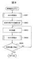
- 6 is a flowchart showing the operation of the map storage mode of the onboard processing device 120.
- 6 is a flowchart showing the operation of a position estimation mode of the onboard processing device 120.
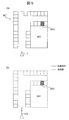
- FIG. 9A is a plan view showing an example of a parking lot 901
- FIG. 9B is a view visualizing a point cloud of landmarks stored in the RAM 122.
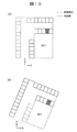
- Fig.10 (a) is a figure which shows an example which visualized point cloud data of point cloud map 124A
- FIG.10 (b) is a figure which shows an example which visualized point cloud data newly detected.
- the figure which shows the data which converted into a parking lot coordinate the point group which the vehicle 1 extracted by the sensor group in the position shown in FIG.
- FIG. 12 is a view showing a comparison between a point cloud map 124A and the local surrounding information 122B shown in FIG.
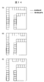
- 14 (a) to 14 (c) are diagrams showing the relationship with the point cloud map 124A when the local peripheral information 122B shown in FIG. 13 is moved by an integral multiple of the width of the parking frame.
- 15 (a) to 15 (c) are diagrams for explaining the matching method when an error occurs during turning.
- FIG. 1 is a block diagram of an automatic parking system 100 including an on-vehicle processing apparatus according to the present invention.
- the automatic parking system 100 is mounted on the vehicle 1.
- the automatic parking system 100 includes sensor groups 102 to 104 and 107 to 109, input / output device groups 110, 111 and 114, control device groups 130 to 133 for controlling the vehicle 1, and an on-vehicle processing device 120.
- the sensor group, the input / output device group, and the control device group are connected to the in-vehicle processing device 120 by signal lines, and exchange various data with the in-vehicle processing device 120.
- the on-vehicle processing device 120 includes an arithmetic unit 121, a RAM 122, a ROM 123, a storage unit 124, and an interface 125.
- the calculation unit 121 is a CPU.
- the calculation unit 121 may be configured to execute all or part of the calculation processing by another calculation processing device such as an FPGA.
- the RAM 122 is a readable and writable storage area, and operates as a main storage device of the on-vehicle processor 120.
- the RAM 122 stores an outlier list 122A described later and local peripheral information 122B described later.
- the ROM 123 is a read only storage area, and stores a program described later. This program is expanded by the RAM 122 and executed by the operation unit 121.
- the computing unit 121 operates as a point cloud acquiring unit 121A, a map generating unit 121B, a position estimating unit 121C, and a mode switching unit 121D by reading and executing a program.
- the storage unit 124 is a non-volatile storage device, and operates as an auxiliary storage device of the on-vehicle processing device 120.
- the storage unit 124 stores a point cloud map 124A.
- the point cloud map 124A is, for example, one or more parking lot data.
- the parking lot data is a set of position information of a certain parking lot, that is, latitude / longitude, coordinates indicating a parking area, and coordinates of points constituting a landmark present in the parking lot. The landmark will be described later.
- the interface 125 exchanges information with the in-vehicle processing device 120 and other devices constituting the automatic parking system 100.
- the sensor group includes a camera 102 for photographing the periphery of the vehicle 1, a sonar 103 or a radar 104 for observing the presence or absence of an object around the vehicle 1, a car navigation system 107, a vehicle speed sensor 108 and a steering angle sensor 109. .
- the camera 102 outputs an image obtained by capturing (hereinafter, a captured image) to the on-vehicle processing device 120.
- the on-vehicle processing device 120 performs positioning of a landmark described later using a captured image of the camera 102.
- the internal parameters such as the focal length of the camera 102 and the image pickup device size, and the external parameters such as the mounting position and mounting posture of the camera 102 on the vehicle 1 are known and stored in the ROM 123 in advance.
- the on-vehicle processor 120 can calculate the positional relationship between the subject and the camera 102 using the internal parameters and the external parameters stored in the ROM 123.
- the sonar 103 and the radar 104 each emit a sound wave or radio wave of a specific wavelength, and observe the position of the reflecting object by measuring the time until the reflected wave that is reflected from the object and received back is received.
- the sonar 103 and the radar 104 observe the position of the reflecting object as a point group and output it to the on-vehicle processing device 120.
- the car navigation system 107 includes a GPS receiver 107A and a storage unit 107B.
- the storage unit 107B is a non-volatile storage device, and stores the road map 107C.
- the road map 107C includes information on the road connection structure and the latitude and longitude corresponding to the road position.
- the car navigation system 107 collates the position information by the GPS receiver 107A with the corresponding road map 107C, and calculates the latitude and longitude of the road position where the vehicle is traveling (navigation self position).
- the accuracy of the latitude and longitude calculated by the car navigation system 107 may not be high, and may include, for example, an error of about several meters to 10 meters.
- the car navigation system 107 outputs the calculated latitude, longitude, and road identification number to the on-vehicle processor 120.
- the GPS receiver 107A receives signals from a plurality of satellites constituting the satellite navigation system, and calculates the position of the GPS receiver 107A, that is, the latitude and the longitude by calculation based on the received signals.
- the accuracy of the latitude and longitude calculated by the GPS receiver 107A may not be high, and may include, for example, an error of about several meters to 10 meters.
- the GPS receiver 107A outputs the calculated latitude and longitude to the car navigation system 107 or the on-vehicle processing device 120.
- the vehicle speed sensor 108 and the steering angle sensor 109 respectively measure the vehicle speed and the steering angle of the vehicle 1 and output them to the on-vehicle processor 120.
- the on-vehicle processing device 120 uses the outputs of the vehicle speed sensor 108 and the steering angle sensor 109 to calculate the movement amount and movement direction of the vehicle 1 by a known dead reckoning technique.
- the input device 110 includes a response button 110A and an automatic parking button 110B.
- the display device 111 is, for example, a liquid crystal display, on which information output from the on-vehicle processing device 120 is displayed.
- the input device 110 and the display device 111 may be integrated, for example, as a liquid crystal display corresponding to a touch operation. In this case, it may be determined that the response button 110A or the automatic parking button 110B has been pressed by touching a predetermined area of the liquid crystal display.
- the communication device 114 is used in order for devices outside the vehicle 1 and the on-vehicle processing device 120 to exchange information using wireless communication. For example, when the user is outside the vehicle 1, the user communicates with a portable terminal worn by the user to exchange information.
- the target with which the communication device 114 communicates is not limited to the portable terminal of the user.
- the vehicle control device 130 controls the steering device 131, the drive device 132, and the braking device 133 based on the operation command of the on-vehicle processing device 120.
- the steering device 131 operates the steering of the vehicle 1.
- the driving device 132 applies a driving force to the vehicle 1.
- the driving device 132 increases the driving force of the vehicle 1 by, for example, increasing the target rotation speed of the engine included in the vehicle 1.
- the braking device 133 applies a braking force to the vehicle 1.
- a landmark is an object having a feature that can be identified by a sensor, and is, for example, a parking frame line, which is one type of road surface paint, or a building wall that is an obstacle that hinders the traveling of a vehicle. In the present embodiment, vehicles and humans that are mobile objects are not included in the landmark.
- the on-vehicle processing device 120 detects landmarks existing around the vehicle 1, that is, points having identifiable features by sensors, based on information input from at least one of the camera 102, the sonar 103, and the radar 104. Do.
- detection of a landmark based on information input from an external sensor that is, information input from at least one of the camera 102, the sonar 103, and the radar 104 is referred to as "landmark positioning”.
- the on-vehicle processing device 120 detects a road surface paint such as a parking frame by operating an image recognition program as described below, for the image captured by the camera 102.
- a road surface paint such as a parking frame
- an edge is extracted from the input image by a Sobel filter or the like.
- a pair of rising of an edge, which is a change from white to black, and falling of an edge, which is a change from black to white is extracted.
- the distance between the pair substantially matches the first predetermined distance determined in advance, that is, the thickness of the white line forming the parking frame, the pair is set as a parking frame candidate.
- a plurality of parking frame candidates are detected by the same processing, and when the intervals between the parking frame candidates substantially coincide with a predetermined second predetermined distance, that is, the white line intervals of the parking frame, they are detected as the parking frame .
- the road surface paint other than the parking frame is detected by an image recognition program that executes the following processing.
- edges are extracted from the input image using a Sobel filter or the like. It is possible to detect by searching for a pixel whose edge strength is larger than a predetermined constant value and the distance between the edges is a predetermined distance corresponding to the width of the white line.
- the on-vehicle processing device 120 detects a vehicle or a human by, for example, known template matching and excludes it from the measurement result. Also, mobiles detected as follows may be excluded from the measurement results. That is, the on-vehicle processing device 120 calculates the positional relationship between the subject in the captured image and the camera 102 using the internal parameter and the external parameter. Next, the on-vehicle processing device 120 calculates the relative velocity between the vehicle 1 and the subject by tracking the subject in the captured images continuously acquired by the camera 102.
- the on-vehicle processing device 120 calculates the speed of the vehicle 1 using the outputs of the vehicle speed sensor 108 and the steering angle sensor 109, and determines that the subject is a moving body if it does not match the relative speed with the subject. , Exclude information on this mobile body from the measurement results.
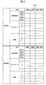
- FIG. 2 is a diagram showing an example of a point cloud map 124A stored in the storage unit 124. As shown in FIG. FIG. 2 shows an example in which two parking lot data are stored as the point cloud map 124A.
- Each parking lot data is composed of coordinates of a parking area, coordinates on a two-dimensional plane of points constituting a landmark, route coordinates traveled at the time of storage, and latitude and longitude corresponding to each coordinate.
- the coordinates of the parking area and the coordinates of the points constituting the landmark are coordinates in a coordinate system (first coordinate system) unique to the parking lot data.
- the coordinate system in parking lot data is called "parking lot coordinate system.”
- the coordinates of the vehicle 1 at the start of recording are the origin
- the traveling direction of the vehicle 1 at the start of recording is the Y axis
- the right direction of the vehicle 1 at the start of recording is the X axis.
- the coordinates of the parking area are recorded as the coordinates of four vertices of the rectangular area, for example, when the parking area is rectangular.
- the parking area is not limited to a rectangular shape, and may be a polygon other than a rectangular shape or an elliptical shape.
- Outlier list 122A In the outlier list 122A, information of points of the local surrounding information 122B which is not processed by the onboard processing device 120 is stored. The outlier list 122A is appropriately updated by the on-vehicle processing device 120 as described later.
- the local peripheral information 122 ⁇ / b> B stores the coordinates of points constituting a landmark detected by the on-vehicle processor 120 in the position estimation mode 203 described later. These coordinates are, for example, coordinates with the position as the origin, the traveling direction of the vehicle 1 as the Y axis, and the traveling direction right as the X axis, based on the position and attitude of the vehicle 1 when recording of the local peripheral information 122B is started. Coordinates in a system (second coordinate system). This coordinate system is hereinafter referred to as "local coordinate system".
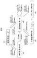
- FIG. 3 is a diagram for explaining the operation mode of the on-vehicle processor 120 and the transition conditions thereof. The operation described by this figure is equal to the operation of the mode switching unit 121D in the on-vehicle processing device 120.
- the on-vehicle processor 120 mainly has five operation modes, that is, a normal travel mode 201, a map storage mode 202, a position estimation mode 203, an automatic parking mode 204, and a give up mode 205.
- the on-vehicle processor 120 starts control of mode switching from the normal driving mode 201.
- the vehicle 1 is driven by the user. At this time, generation of a point cloud map or self-position estimation on the point cloud map is not performed, and only monitoring of a mode transition condition is performed.
- the mode transition is a comparison of the latitude / longitude (navi self position) of the self position obtained from the car navigation system 107 with the latitude / longitude near the point (registration point) where parking is desired to be registered beforehand.
- the mode transition is performed when the navigation self position enters within the 100 m range of the registration point.
- transition to the map storage mode 202 is made, and if a point cloud map near a point currently traveling is registered, transition is made to the position estimation mode 203 . It is determined from the latitude and longitude information corresponding to the landmark whether or not the nearby point cloud map is registered. The latitude longitude information of the self position and the latitude longitude information of the landmark are compared, and if there is a landmark within the predetermined distance, the map is registered, and if there is no landmark within the predetermined distance, the map is not Judge as registration.
- the vehicle 1 is driven by the user, and the on-vehicle processing device 120 is based on the information from the sensors provided in the vehicle 1, that is, parking lot data, that is, white line and obstacle information present in the parking lot and And collect information on travel routes.
- the on-vehicle processor 120 stores the collected information in the storage unit 124 as a point cloud map 124A.
- the latitude / longitude near the point (parked point) you want to park in advance is compared with the latitude / longitude information of the self position acquired from the car navigation system 107, and outside the fixed range centered on the registered point If the navigation self position is away from the registration point and the distance becomes 100 m or more, for example, the map storage mode 202 is transited to the normal travel mode 201. When the user enters a point group map registered section halfway, the map storage mode 202 is transitioned to the position estimation mode 203.
- the latitude / longitude information of the self position is compared with the latitude / longitude information of the landmark as to whether or not the own vehicle has entered the map registered section, and is predetermined based on the navigation self position. It is judged by whether or not there is a landmark (corresponding point group) within the distance. Then, if there is a landmark, it is determined that the vehicle has entered a section registered with the map.
- the vehicle 1 is driven by the user, and the on-vehicle processing device 120 collates the information from the sensors included in the vehicle 1 with the information of the point cloud map 124A to estimate the position of the vehicle in the point cloud map. .
- the on-vehicle processor 120 detects a white line or an obstacle present around the vehicle 1 based on the information from the sensor, and estimates the current position by collating with the point cloud map 124A.
- the latitude and longitude of the registration point is compared with the latitude and longitude information of the self position acquired from the car navigation system 107, and when the vehicle comes out from within a certain range centered on the registration point, for example When the navigation self position is away from the registration point and the distance becomes 100 m or more, the transition from the position estimation mode 203 to the normal travel mode 201 is made. When entering an unregistered section of the point group map from the middle, it is determined that there is no corresponding point group, and the transition from the position estimation mode 203 to the map storage mode 202 is made.
- the latitude / longitude information of the self position and the latitude / longitude information of the landmark are compared, and land within a predetermined distance centered on the self position. It is judged whether or not there is a mark (corresponding point group), and if there is no landmark, it is judged that the vehicle has entered an unregistered section of the point cloud map.
- automatic estimation from the position estimation mode 203 is performed only while the position estimation of the own vehicle is successful, and the self position is within a predetermined range from the parking position, and while the user is pressing the automatic parking button 110B.
- a transition to the parking mode 204 is made. That is, automatic control is performed based on the user's approval.
- transition to the give up mode 205 is made.
- the vehicle 1 is controlled by the on-vehicle processing device 120, and the self position in the point cloud map obtained in the position estimation mode 203 and the self position estimation result in the map continuously performed in the automatic parking mode 204 , The vehicle 1 is parked at the parking position stored in the point cloud map.
- the on-vehicle processor 120 continues to the position estimation mode 203 and detects white lines and obstacles existing around the vehicle 1 based on the information from the sensor and collates it with the point cloud map 124A. Estimate the current position. For mode transition, when the user releases the automatic parking button 110B, transition from the automatic parking mode 204 to the position estimation mode 203 is made. That is, automatic parking control is stopped. If the user's own position is lost in a state where the user presses the automatic parking button 110B, transition to the give up mode 205 is made.
- the mode transition when the user completes parking or is separated from the registration point by a predetermined distance, the mode transits to the normal driving mode 201.
- the map storage mode 202, the position estimation mode 203, and the automatic parking mode 204 will be described in detail below.
- Map memory mode 202 When a point cloud map is not recorded (no corresponding point group) within the predetermined range centered on the registration point, the on-vehicle processing device 120 transitions from the normal travel mode 201 to the map storage mode 202. For example, when the navigation self position falls within the range of 100 m centered on the registration point, and there is no corresponding point group, the map storage mode 202 is operated. While operating in the map storage mode 202, the screen of the display device 111 indicates that the map storage mode 202 is operating. Then, when the user moves to the parking position and then stops and operates the parking brake, the display device 111 is triggered by the activation of the parking brake, "Does the area around this traveling route be stored as a map?" The words are displayed.
- the map storage mode 202 is ended without storing the vicinity of the current travel route as a map.
- the operation of the map storage mode 202 by the on-vehicle processing device 120 is divided into two processes of extraction of a point group constituting a landmark and recording of the extracted point group.
- a process of extracting a point cloud by the on-vehicle processor 120 will be described.
- the on-vehicle processor 120 secures a temporary recording area in the RAM 122. Then, the on-vehicle processor 120 repeats the following processing until the map storage mode 202 ends or transitions to another mode. That is, the on-vehicle processing device 120 extracts a point group constituting a landmark based on at least one of a captured image of the camera 102 and observation information by the sonar 103 and the radar 104.
- the on-vehicle processing device 120 calculates, based on the outputs of the vehicle speed sensor 108 and the steering angle sensor 109, the movement amount and movement direction in which the vehicle 1 has moved from the previous shooting to the current shooting. Then, the on-vehicle processing device 120 records, in the RAM 122, a point group extracted based on the positional relationship with the vehicle 1, the movement amount and the movement direction of the vehicle 1. Furthermore, the on-vehicle processor 120 records the latitude and longitude output from the car navigation system 107 together with the point group. The on-vehicle processor 120 repeats this process.
- the position of the vehicle 1 and the coordinates of the point group are recorded as coordinate values of the recording coordinate system.
- the position of the vehicle 1 at the start of recording is taken as the origin (0, 0)
- the traveling direction (posture) of the vehicle 1 at the start of recording is the Y axis
- It is treated as a coordinate value of a coordinate system with the right direction as the X axis. Therefore, even if the point cloud is recorded in the same parking lot, the recording coordinate system set by the position and attitude of the vehicle 1 at the start of recording is different, so the point cloud constituting the landmark is recorded at different coordinates. Ru.
- the user parks the vehicle at the target parking position and applies the parking brake.
- the display device 111 displays the words "Do you want to store the area around this travel route as a map?".
- the response button 110A When the user presses the response button 110A, the map is stored.
- the on-vehicle processor 120 When the on-vehicle processor 120 is approved to store the map, the on-vehicle processor 120 records the current position on the RAM 122 as the parking position.
- the parking position is recorded, for example, as the coordinates of the four corners when the vehicle 1 is approximated to a rectangle.
- the on-vehicle processor 120 performs point cloud recording processing as follows.
- the on-vehicle processing device 120 determines whether or not the recorded coordinates of the parking lot, that is, the latitude and longitude substantially match the coordinates of any parking lot already recorded in the point cloud map 124A. If the two do not substantially match, the on-vehicle processor 120 records the point cloud information stored in the RAM 122 in the point cloud map 124A as new parking lot data. If the both substantially match, the on-vehicle processing device 120 determines whether to merge (integrate) the information of the point group where the coordinates of the parking lot substantially match as a point group of one parking lot.
- the on-vehicle processor 120 first performs coordinate conversion so that the parking position included in the parking lot data matches the parking position recorded in the RAM 122, and then the point cloud in the point cloud map 124A and the RAM 122 The degree of point cloud coincidence, which is the degree of coincidence with the stored point cloud, is calculated. Then, the on-vehicle processing device 120 determines that the calculated point cloud coincidence is merged if the calculated degree of point cloud coincidence is larger than the threshold, and determines not to merge if it is equal to or less than the threshold. The calculation of the degree of point cloud coincidence will be described later.
- the on-vehicle processing device 120 When it is determined that merging is not performed, the on-vehicle processing device 120 records the point cloud stored in the RAM 122 as new parking lot data in the point cloud map 124A. When it is determined that merging is performed, the on-vehicle processing device 120 adds the point cloud stored in the RAM 122 to the existing parking lot data of the point cloud map 124A.
- FIG. 4 is a flowchart showing the operation of the map storage mode 202 of the on-vehicle processor 120.
- the execution subject of each step described below is the computing unit 121 of the on-vehicle processor 120.
- the calculation unit 121 functions as the map generation unit 121B when performing the process shown in FIG.
- step S501 it is determined whether the map storage mode 202 has been entered. If it is determined that the map storage mode 202 has been entered, the process proceeds to step S501A. If the map storage mode 202 has not been entered, the process remains at step S501. In step S501A, a new recording area is secured in the RAM 122. In this storage area, the extracted point group and the current position of the vehicle 1 are recorded in the coordinates of the above-mentioned recording coordinate system.
- step S 502 information is acquired from the sensor group and the above-described landmark positioning, that is, extraction of a point group constituting a landmark using the photographed image of the camera 102, the sonar 103, and the radar 104 and output from the car navigation system 107 Link with the observed latitude and longitude values.
- step S 503 the moving amount of the vehicle 1 in the time from the sensing of the camera 102, the sonar 103 and the radar 104 to the latest sensing is estimated, and the current position of the vehicle 1 in the recording coordinate system recorded in the RAM 122 Update.
- the moving amount of the vehicle 1 can be estimated by a plurality of means.
- the moving amount of the vehicle 1 can be estimated from the change in the position of the object present on the road surface in the captured image of the camera 102. It may be estimated from the sensing results of the sonar 103 and the radar 104. When a high accuracy GPS receiver with a small error is mounted as the car navigation system 107, the output may be used. The movement amount of the vehicle 1 may be estimated from the vehicle speed sensor 108 and the steering angle sensor 109. Next, the process proceeds to step S504.
- step S504 the point group extracted in step S502 is stored in the RAM 122 as coordinates of the recording coordinate system based on the current position updated in step S503.
- step S505 it is determined whether or not the storage approval operation for pressing the response button 110A has been performed, and if it is determined that the storage approval operation has been performed, the process proceeds to step S505A, and it is determined that the storage approval operation is not performed. It returns to step S502.
- step S505A the current latitude and longitude of the vehicle 1 is acquired from the car navigation system 107, and the coordinates of the parking position, that is, the current position of the vehicle 1 and in the recording coordinate system of the four corners of the vehicle 1 are recorded.
- step S506 the current latitude and longitude of the vehicle 1 is acquired from the car navigation system 107, and the coordinates of the parking position, that is, the current position of the vehicle 1 and in the recording coordinate system of the four corners of the vehicle 1 are recorded.
- step S506 it is determined whether parking lot data having a latitude and longitude substantially matching the current latitude and longitude of the vehicle 1 acquired in step S505A is recorded in the point cloud map 124A. If it is determined that the current latitude and longitude of the vehicle 1 substantially matches the latitude and longitude of any of the parking lot data recorded in the point group map 124A, the process proceeds to step S507. Otherwise, the process proceeds to step S510.
- parking lot data of the point cloud map 124A in which it is determined that the current latitude and longitude of the vehicle 1 substantially coincide with each other will be referred to as target parking lot data.
- step S507 the recording coordinate system, which is the coordinate system of the point cloud data stored in the RAM 122, is converted to the coordinate system of the point cloud data of the target parking lot data based on the parking position. That is, the coordinate transformation formula of the recording coordinate system and the parking lot coordinate system is derived such that the parking position included in the target parking lot data coincides with the parking position recorded in step S505A. Then, by using this coordinate conversion formula, the coordinates of the points constituting the landmark stored in the recording coordinate system in the RAM 122 are converted into the parking lot coordinate system of the target parking lot data.
- a point cloud coincidence rate IB between the point cloud data stored in the RAM 122 and the target parking lot data is calculated.
- Equation 1 is the number of points within which the distance between each point of the point cloud data subjected to the coordinate conversion in step S507 and each point of the target parking lot data is within a predetermined distance.
- Equation 1 “D1” is the number of points in the point cloud data stored in the RAM 122, and “D2” is the number of points in the point cloud data of the target parking lot data.
- step S508 it is determined whether the point cloud matching rate IB calculated in step S507A is larger than a predetermined threshold. If it is determined that the point cloud coincidence rate IB is larger than the threshold, the process proceeds to step S509. If it is determined that the point cloud coincidence rate IB is equal to or less than the threshold, the process proceeds to step S510.
- step S509 the point cloud data subjected to coordinate conversion in step S507 is added to the merging process, that is, the target parking lot data of the point cloud map 124A stored in the storage unit 124.
- step S510 which is executed when a negative determination is made in step S506 or step S508, the point cloud data stored in the RAM 122, the latitude and longitude of the vehicle 1 recorded in step S505A, and the parking position are used as new parking lot data.
- the group map 124A is recorded. This is the end of the flowchart of FIG.
- Position estimation mode 203 When it is determined that the user drives the vehicle 1 to move to the vicinity of the registration point, and it is determined that the peripheral point cloud map is stored, the transition from the normal travel mode 201 to the position estimation mode 203 is made. For example, when the navigation self position falls within the range of 100 m centered on the registration point and there is a corresponding point group, the position estimation mode 203 is operated. The operation of the on-vehicle processor 120 at this time will be described below with reference to a flowchart.
- FIG. 5 is a flowchart showing the operation of the position estimation mode of the on-vehicle processor 120.
- the execution subject of each step described below is the computing unit 121 of the on-vehicle processor 120.
- the on-vehicle processor 120 specifies a point cloud (parking spot point group) having a latitude and longitude substantially matching the current position of the vehicle 1 among the plurality of parking lot data included in the point cloud map 124A (step S601).
- the on-vehicle processing device 120 performs initialization of the local surrounding information 122B stored in the RAM 122 as initialization processing, and initialization of the current position of the vehicle 1 stored in the RAM 122 (step S601A). Specifically, if conventional information is recorded, it is erased and a new coordinate system is set. In this embodiment, this coordinate system is called a local coordinate system. This local coordinate system is set based on the position and attitude of the vehicle 1 when step S601A is performed.
- the position of the vehicle 1 when step S601A is performed is set to the origin of the local coordinate system, and the X axis and the Y axis are set according to the direction when step S601A is performed. Further, in the initialization of the current position of the vehicle 1, the current position of the vehicle 1 is set to the origin (0, 0).
- step S603 it is determined whether the self position can be estimated. If it is determined that the estimation has been completed, the processing proceeds to step S604. If it is determined that the estimation can not be performed, the processing returns to step S602.
- step S604 the on-vehicle processing device 120 displays the self position estimation result on the map on the display device 111, and in the subsequent step S605, determines whether or not the self position falls within a predetermined range from the storage parking position. . For example, when the vehicle 1 approaches the storage parking position to the distance Nm, it is determined that the vehicle 1 is within the predetermined range. If it is determined that it is within the predetermined range, the process proceeds to step S606, and if it is determined that it is not within the predetermined range, that is, it is determined that it is out of range, the process returns to step 604.
- step S606 the on-vehicle processing device 120 displays that automatic parking is possible on the display device 111, and in the subsequent step S607, it is determined whether or not the automatic parking button 110B has been pressed by the user. If it is determined that the automatic parking button 110B has been pressed, the process proceeds to step S608 to shift to the automatic parking mode, and the automatic parking process is executed according to the procedure shown in FIG. The process returns to step S606.
- the computing unit 121 functions as a local peripheral information creating unit when performing the processing shown in steps S621 to S623 of FIG. 6A.
- step S621 The landmark positioning in step S621, the movement estimation of the vehicle in step S622, and the update of the local surrounding information 122B in step S623 are substantially the same as the processing in steps S502 to S504 in FIG. The difference is that the data stored in the RAM 122 is recorded as the local peripheral information 122B.
- step S623A the on-vehicle processor 120 selects local surrounding information whose details are shown in FIG. 6B (step S623A).
- the selection processing of the local peripheral information is processing for selecting a point to be used in the matching processing in step S624 described later, from the point group obtained as the local peripheral information.
- the point cloud obtained from the local peripheral information may not be matched with the point cloud map because the overall shape thereof is different due to the accumulated error of the movement estimation of the vehicle.
- this local peripheral information selection processing a point group in a range in which the shape error is small and which can be matched is adaptively selected.
- step S624 the on-vehicle processing device 120 performs a matching process whose details are shown in FIG. 7 (step S624).
- this matching process the correspondence relationship between the parking space coordinate system and the local coordinate system, that is, the coordinate conversion equation between the parking space coordinate system and the local coordinate system is obtained.
- step S625 the on-vehicle processing device 120 uses the coordinates of the vehicle 1 in the local coordinate system updated in step S622 and the coordinate conversion equation obtained in step S625 to calculate the coordinates of the vehicle 1 in the parking lot coordinate system, Calculate the position.
- step S626 the process proceeds to step S626.
- step S626 the on-vehicle processor 120 executes a self-diagnosis to determine the reliability of the position calculated in step S625.
- Self-diagnosis is judged using, for example, the following three indicators.
- the first index compares the amount of movement of the vehicle 1 estimated by the known dead reckoning technique using the outputs of the vehicle speed sensor 108 and the steering angle sensor 109 with the amount of movement in a predetermined period estimated by self position estimation, If the difference is larger than a predetermined threshold value, it is determined that the reliability is low.
- the second index is determined by the amount of error of the corresponding point calculated at the time of matching. If the amount of error is larger than a predetermined threshold value, it is determined that the reliability is low.
- the third indicator it is determined whether there is a similar solution.
- a similar solution for example, by translating the obtained solution by the width of the parking frame, it is determined that the reliability is low when there are the same number of points whose corresponding point errors are within a certain range. It is determined that the self-position can be estimated if it is not determined that the reliability is low in all of these three indicators.
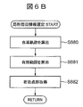
- the calculation unit 121 functions as a local peripheral information selection unit when performing the process shown in FIG. 6B.
- step S680 the trajectory to the current position of the vehicle is calculated using the vehicle movement amount calculation implemented in step S622.
- the locus generated by interpolating the coordinate points of the host vehicle position calculated from the host vehicle movement amount is the host vehicle locus.
- step S 681 for the point group of local peripheral information, a shape error is small, and a matching effective range is calculated.
- This effective range is determined from the length and shape of the vehicle trajectory calculated in step S680.
- an estimation error of the moving amount easily occurs. Conversely, if there are too few point clouds, matching will be difficult. Therefore, a point cloud in a range in which the minimum distance D [m] determined in advance from the current position is traced back along the trajectory is acquired.
- a point group in a range X [m] ⁇ Y [m] predetermined in advance with the locus at the center is set as an effective range of the point group of the local peripheral information. That is, the effective range has a shape along the obtained trajectory.
- step S682 a point within the effective range obtained in step S681 is acquired as a point cloud of local peripheral information.
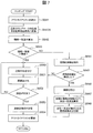
- the calculation unit 121 functions as a position estimation unit 121C when performing the process shown in FIG. 6A.
- step S641 the outlier list 122A stored in the RAM 122 is applied to the local peripheral information 122B to temporarily exclude the points described in the outlier list 122A among the point clouds included in the local peripheral information 122B.
- This application range is steps S642 to S653.
- step S654 points that were previously included in the outlier list 122A are also included.
- the steps S641 to S643 can not be executed at the first execution of the flowchart shown in FIG. 7, the execution is started from the step S650. Next, the process proceeds to step S641A.
- step S641A the coordinates of the point cloud detected from the latest captured image, that is, the point cloud constituting the landmark detected in step S621 of FIG. 6A, are converted into coordinates of the parking lot coordinate system. This conversion is realized by using the position of the vehicle 1 in the local coordinate system updated in step S 622 and the coordinate conversion formula from the local coordinate system calculated previously to the parking space coordinate system.
- the degree of instantaneous coincidence IC is calculated.
- step S643 it is determined whether the degree of instantaneous coincidence IC calculated in step S642 is larger than a threshold. If it is determined that the momentary coincidence degree IC is larger than the threshold value, the process proceeds to step S650. If it is determined that the momentary coincidence degree IC is equal to or less than the threshold value, the process proceeds to step S644.
- step S644 periodic features, for example, a plurality of parking frames arranged in a row, are detected from the target parking lot data of the point cloud map 124A, that is, the point cloud data.
- the parking frame line can be detected from the points arranged at intervals equivalent to the thickness of the white line.
- step S645 it is determined whether or not the periodic feature is detected in step S644. If it is determined that it has been detected, the process proceeds to step S646, and if it is determined that it has not been detected, the process proceeds to step S650.
- step S646 the period of the periodic feature, for example, the width of the parking frame is calculated. The width of the parking frame referred to here is the interval between white lines constituting the parking frame.
- step S647 the period of the periodic feature, for example, the width of the parking frame is calculated. The width of the parking frame referred to here is the interval between white lines constituting the parking frame.
- step S 647 based on the coordinate conversion formula calculated in the previous step S 653, the coordinate conversion formula is changed in a plurality of ways to calculate the overall matching degree IW.
- the coordinate transformation equation is changed in multiple ways so as to be shifted by an integral multiple of the periodic feature detected by the point cloud map.
- Equation 3 “DWin” is the distance to the point constituting the closest point cloud map 124A among the points obtained by converting the points constituting the local peripheral information 122B into the parking lot coordinate system using the above-mentioned coordinate conversion formula Is the number of points below the predetermined threshold. Further, in Equation 3, “DWall” is the number of points detected in step S621. Next, the process proceeds to step S648.
- step S648 a coordinate conversion equation giving the largest overall coincidence IW among the plurality of overall coincidences IW calculated in step S647 is stored in the RAM 122, and the flow proceeds to step S650.
- the matching process in step S650, the error minimizing process in step S651, and the convergence determination process in step S625 can use an ICP (Iterative Closest Point) algorithm, which is a known point cloud matching technique.
- ICP Intelligent Closest Point
- step S650 is executed.
- the correspondence between the point group included in the parking lot data and the point group included in the local peripheral information 122B is calculated.
- step S643 or step S648 the point cloud data of the local peripheral information 122B uses a value subjected to coordinate conversion using the coordinate conversion equation stored in the RAM 122.
- step S643 when an affirmative determination is made in step S643 and step S650 is executed, the coordinate conversion formula calculated in step S653 executed last time is used. On the other hand, when step S650 is executed following step S648, the coordinate conversion equation stored in step S648 is used. Next, the process proceeds to step S651.
- step S651 the coordinate conversion equation is changed such that the error of the corresponding point is minimized.
- the coordinate conversion equation is changed such that the sum of the indices of the distances between the points associated in step S650 is minimized.
- the sum of absolute values of distances can be adopted as the sum of indices of distances between associated points.
- step S652 it is determined whether the error has converged. If it is determined that the error has converged, the process proceeds to step S653. If it is determined that the error has not converged, the process returns to step S650. In the subsequent step S653, the coordinate conversion equation changed in step S651 is finally stored in the RAM 122, and the process proceeds to step S654.
- step S654 the outlier list 122A is updated as follows. First, the existing outlier list 122A stored in the RAM 122 is cleared. Next, the point group of the local peripheral information 122B is converted to the parking lot coordinate system using the coordinate conversion formula recorded in step 653, and each point constituting the local peripheral information 122B and the point cloud map 124A corresponding to that point Calculate the distance to the point to be configured, that is, the Euclidean distance. Then, if the calculated distance is longer than the predetermined distance, the point of the local peripheral information 122B is added to the outlier list 122A. However, at this time, spatial end positions may be added as a further condition to be added to the outlier list 122A. The spatial end is a point at which the distance to another point is long, such as a point acquired when recording is started. The outlier list 122A is updated by the above processing. This is the end of the flowchart of FIG.
- Automatic parking from self position estimation mode 203 only while the position estimation of the host vehicle is successful, and the self position is within a predetermined range from the parking position, and while the user is pressing the automatic parking button 110B.
- a transition to mode 204 is made. That is, automatic control is performed based on the user's approval.
- step S661 the position of the vehicle 1 in the parking lot coordinate system is estimated.
- the processing in this step is the same as step S604 in FIG.
- step S662 a travel route from the position estimated in step S661 to the parking position stored in the point cloud map 124A is generated by a known route generation method.
- step S663 the process proceeds to step S663.
- step S663 the steering device 131, the drive device 132, and the braking device 133 are controlled via the vehicle control device 130, and the vehicle 1 is moved to the parking position along the route generated in step S662. Only when the automatic parking button 110B is kept pressed by the user, an operation command is output to the driving device 132. Further, when a person or a moving vehicle is extracted from the photographed image of the camera 102, the sonar 103 and the radar 104, the braking device 133 is operated to stop the vehicle 1. In the subsequent step S664, the position of the vehicle 1 is estimated as in step S661.
- step S665 it is determined whether the parking is completed, ie, whether or not the vehicle 1 has reached the parking position, and if it is determined that the parking is not completed, the process returns to step S663 to determine that the parking is completed. If so, the flowchart of FIG. 8 is ended.
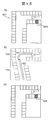
- FIG. 9A is a plan view showing an example of the parking lot 901.
- a parking lot 901 is provided around the building 902. There is only one entrance of the parking lot 901 at the lower left of the figure.
- a square shown in FIG. 9A represents a parking frame which is road surface paint, and a hatched parking frame 903 is a parking area of the vehicle 1 (an area which becomes a parking position when parking is completed).
- the landmark is described as only the parking frame line.
- the vehicle 1 is indicated by a triangle, and the acute angle of the triangle indicates the traveling direction of the vehicle 1.
- Map memory mode 202 Part 1 When transiting from the normal driving mode 201 to the map storage mode 202 near the entrance of the parking lot 901, the on-vehicle processor 120 starts landmark positioning, and records the coordinates of the points constituting the parking frame line (step S501 in FIG. 4). : YES, S502 to S504). Then, the vehicle 1 repeats the processing of steps S502 to S504 of FIG. 4 until the response button 110A is pressed and the storage processing is approved.
- FIG. 9B is a diagram visualizing a point group of landmarks stored in the RAM 122.
- a solid line indicates a point cloud of landmarks stored in the RAM 122
- a broken line indicates landmarks not stored in the RAM 122. Since the camera 102, the sonar 103, and the radar 104 of the vehicle 1 have a limited sensing range, the vicinity of the entrance of the parking lot 901 when the vehicle 1 is near the entrance of the parking lot 901 as shown in FIG. Only the parking line is recorded. When the user moves the vehicle 1 to the back of the parking lot 901, the on-vehicle processor 120 can record the point cloud of the entire landmark of the parking lot 901.
- the on-vehicle processing device 120 acquires the latitude and longitude of the vehicle 1 from the car navigation system 107 and The coordinates of are recorded (step S505: YES, S505A).
- step S506 NO
- point cloud data shown in FIG. 10A is recorded as parking lot data of point cloud map 124A and point cloud data shown in FIG. 10B is newly obtained will be described.
- the point cloud data shown in FIG. 10A is, for example, point cloud data obtained when traveling from the entrance of the parking lot 901 shown in FIG. 9A to the right and reaching the parking position.
- the vehicle 1 is shown in FIG. Since the vehicle has traveled to the right compared to (a), the point cloud data of the parking frame indicated by the broken line in FIG. 10A is not acquired.
- the point cloud data shown in FIG. 10B is, for example, point cloud data obtained when traveling from the entrance of the parking lot 901 to the left and reaching the parking position. Since the vehicle has traveled to the left compared to FIG. 9A, the point cloud data of the parking frame indicated by the broken line in FIG. 10B is not acquired.
- the parking lot 901 is inclined as compared to FIG. 10 (a) because the vehicle 1 does not face the parking lot 901 when transitioning to the storage mode. It is recorded in.
- step S506 when the user approves the storage with the response button 110A, it is determined that the latitude and longitude substantially matching the current latitude and longitude of the vehicle 1 are recorded in the point cloud map 124A (S506: YES) Coordinate conversion is performed on the basis of the parking positions shown in FIGS. 10A and 10B, that is, the parking frame 903 (step S507). Then, point cloud coincidence rate IB is calculated (step S507A), and if it is determined that point cloud coincidence rate IB is larger than a predetermined threshold (step S508: YES), merge processing is performed, as shown in FIG. The point cloud data shown in FIG. 10B is integrated with the point cloud data (step S509). By this integration, the point cloud of the parking frame line on the left side of the illustration not recorded in FIG. 10A is newly recorded, and the parking frame line on the right side or the upper part of the illustration already recorded is configured. The density of the group is increased.
- FIG. 11 is a diagram showing the current position of the vehicle 1 in the parking lot 901 shown in FIG. 9 (a).
- the vehicle 1 is directed upward in the figure. 12 to 13 show parking frame lines of a portion surrounded by a broken line circle in FIG. 10 which is a front area of the vehicle 1.
- FIG. 12 is a diagram showing data obtained by converting the point group sensed and extracted by the sensor group at the position shown in FIG. 11 into parking lot coordinates. That is, the point group shown in FIG. 12 is a point group detected from the latest captured image in the local peripheral information 122B, and is data processed in step S641A in FIG. However, in FIG. 12, they are not dotted but represented as broken lines. Further, in FIG. 12, the vehicle 1 is also displayed for comparison with FIG. 11. As shown in FIG. 12, point cloud data of the parking frame line continuously exists on the left side of the vehicle 1, and point cloud data of the parking frame line exists only on the front side of the vehicle 1 on the right side.
- FIG. 13 is a diagram showing a comparison between the point cloud map 124A and the local surrounding information 122B shown in FIG. 11 when the estimation of the position of the vehicle 1 in the parking lot coordinate system includes an error.
- the local peripheral information 122B present on the right side of the vehicle 1 is offset from the point cloud map 124A.
- the momentary coincidence IC is calculated in such a state (step S642 in FIG. 7), the momentary coincidence IC has a low value due to the above-mentioned deviation on the right side of the vehicle 1.
- step S643 NO
- the parking frame is detected as a periodic feature (steps S644, S645: YES), and the width (period) of the parking frame is obtained from the point cloud map 124A. Is calculated (step S646) and moved by an integral multiple of the width of the parking frame to calculate the overall matching score IW (step S647).
- FIGS. 14 (a) to 14 (c) are diagrams showing the relationship with the point cloud map 124A when the local peripheral information 122B shown in FIG. 13 is moved by an integral multiple of the width of the parking frame.
- the local peripheral information 122B shown in FIG. 14 is moved upward by +1, 0 and -1 times the width of the parking frame.
- the local peripheral information 122B is moved upward by one of the width of the parking frame, and the gap between the local peripheral information 122B and the point cloud map 124A is enlarged. Therefore, the overall matching score IW in FIG. 14A is smaller than that in the case of not moving.
- FIG. 14B the local peripheral information 122B is not moved, and as seen in FIG.
- the local peripheral information 122B and the point cloud map 124A are shifted by one width of the parking frame.
- the local peripheral information 122B is moved downward by one of the width of the parking frame, and the local peripheral information 122B substantially matches the point cloud map 124A. Therefore, the overall matching score IW in FIG. 14C is larger than that in the case of not moving.
- the overall match degree IW corresponding to FIG. 14C is determined to be the maximum in the example shown in FIG.
- the coordinate conversion equation to be stored is stored in the RAM 122 (step S648).
- the on-vehicle processor 120 improves the position accuracy to be estimated.
- FIG. 15 is a diagram showing a comparison between the point cloud map 124A and the local surrounding information 122B shown in FIG. 11 when the estimation of the position of the vehicle 1 in the parking lot coordinate system includes an error.
- FIG. 15 (a) shows the current position of the vehicle 1 in the parking lot 901 shown in FIG. 9 (a).
- the vehicle 1 is directed to the right in the figure.
- FIG.15 (b) is a figure which shows the data which converted into the parking lot coordinate the point cloud extracted from the image image
- the traveling locus has an effective portion 151 and an invalid portion 152, and the point cloud of the local peripheral information is divided into an effective range 153 and an ineffective range 154.
- FIG. 15C shows the result of matching using the point group in the effective range 153.
- the point group in a predetermined range centering on the effective portion 151 of the vehicle trajectory is set as the effective range 153 of the point group of the local peripheral information by the process of step S681 in FIG. 6B.
- the effective part 151 of the traveling locus ends at a part where the traveling locus is traced back from the self position in the reverse direction and is largely turned.
- a point (point within the effective range) falling within a predetermined range centering on the effective portion 151 of the traveling locus is acquired as a point cloud of local peripheral information and used for matching.
- a point (point within the ineffective range 154) that falls within a predetermined range around the ineffective portion 152 of the travel locus is not used for matching. Therefore, correct matching can be performed.
- the in-vehicle processing device 120 stores the point cloud data (point cloud map 124A) including a plurality of coordinates in the first coordinate system (parking lot coordinate system) of points representing a part of the object, and A sensor input unit (interface 125) for acquiring an output of the camera 102 for acquiring information around the vehicle 1, a movement information acquisition unit (interface 125) for acquiring information on movement of the vehicle 1, a sensor input unit, Based on the information acquired by the movement information acquisition unit, a local periphery including a plurality of coordinates in the second coordinate system (local coordinate system) of the position of the vehicle in the second coordinate system (local coordinate system) and a part representing an object The relationship between the first coordinate system and the second coordinate system is estimated based on the local peripheral information creation unit that generates the information 122B, the point cloud map 124A and the local peripheral information 122B, and the car in the first coordinate system is And a position estimation unit 121C for estimating
- the on-vehicle processing device 120 estimates coordinate transformation formulas of the parking lot coordinate system and the local coordinate system based on the point cloud map 124A and the local peripheral information 122B, and estimates the position of the vehicle 1 in the parking lot coordinate system.
- the point cloud map 124A is information stored in advance in the storage unit 124, and the local surrounding information 122B is generated from the outputs of the camera 102, the vehicle speed sensor 108, and the steering angle sensor 109. That is, the on-vehicle processing device 120 acquires information of point groups in a coordinate system different from the recorded point group coordinate system, and the position of the vehicle 1 in the recorded coordinate system based on the correspondence between different coordinate systems. Can be estimated.
- the on-vehicle processing device 120 estimates coordinate transformation formulas of the parking lot coordinate system and the local coordinate system based on the point cloud map 124A and the local peripheral information 122B, noise is generated in part of point cloud data of the local peripheral information 122B. It is hard to be affected even if it is included. That is, the position estimation of the vehicle 1 by the on-vehicle processing device 120 is resistant to disturbances.
- the position estimation unit 121C searches for points corresponding to each point constituting the local peripheral information 122B from the point cloud data (step S650 in FIG. 7), and the distance between the corresponding points is minimized. As described above, coordinate transformation formulas of the first coordinate system and the second coordinate system are estimated (step S651 in FIG. 7).
- the position estimation unit 121C excludes point data of local peripheral information that is longer than a predetermined threshold, and the point constituting the point cloud data or the local peripheral information 122B and the distance to the point corresponding to this point In other words, the outlier list 122A is applied (steps S641 and S653 in FIG. 7) to perform search and estimation. Therefore, since the point group data whose distance which can be regarded as a noise component is separated is excluded from the calculation target, the accuracy of the coordinate conversion equation can be improved.
- Point cloud data and points included in local peripheral information are represented as coordinates in a two-dimensional space.
- the position estimation unit 121C performs the search and estimation excluding the point at which the distance between corresponding points is longer than a predetermined threshold and spatially located at the end of the local peripheral information 122B.
- the point cloud stored in the parking lot data of the point cloud map 124A relates to a landmark closer to the parking position than the point at which the user pressed the recording start button 110A.
- local peripheral information 122B includes a point which does not correspond to any point stored in the parking lot data. If ICP is processed including steps such as these, that is, steps S650 to S652 in FIG. 7, an appropriate solution can not be obtained. Therefore, by eliminating these, it is possible to obtain an appropriate solution.
- Point cloud data includes periodic features.
- the position estimation unit 121C estimates the coordinate conversion formula between the first coordinate system and the second coordinate system, and then reduces the distance between the corresponding points based on the distance of one period of the periodic feature so that the distance between the corresponding points becomes short.
- the coordinate conversion equation between the one coordinate system and the second coordinate system is corrected (steps S646 to S648 in FIG. 7).
- step S641A the processing of steps S 644 to S 648 in FIG. 7 is not performed constantly, but is performed only when it is determined necessary in consideration of the necessity of the processing.
- the on-vehicle processing device 120 has coordinates in the third coordinate system (recording coordinate system) of points representing a part of the object excluding the moving object based on the information acquired by the sensor input unit and the movement information acquisition unit.
- the point cloud acquisition unit 121A is configured to create a plurality of pieces of second point cloud data and store the second point cloud data as the point cloud map 124A in the storage unit 124. Therefore, the on-vehicle processor 120 can create the point cloud map 124A when the vehicle 1 equipped with the on-vehicle processor 120 travels.
- the creation process of the point cloud map 124A and the position estimation process of the vehicle 1 are common in terms of landmark positioning, and program modules can be used in common.
- the third coordinate system (recording coordinate system) is set based on the position and attitude of the vehicle when the creation of the second point group data is started.
- the point cloud acquisition unit 121A determines the parking position of the vehicle 1
- a plurality of second point group data are integrated by estimating the relationship between different coordinate systems as a reference (steps S507 and S509 in FIG. 4). Therefore, even if different recording coordinate systems are set each time point cloud data is acquired, a plurality of point cloud data can be integrated. This focuses on the point at which the vehicle 1 is parked at the same parking position although the position at which acquisition of point cloud data is started and the attitude of the vehicle 1 at that time are various.
- the on-vehicle processing device 120 drives the vehicle based on the output of the position estimation unit 121C and moves the vehicle to a parking position designated in advance in the first coordinate system, and information on the position of the vehicle 1
- the points constituting the point cloud map 124A are points representing a part of the composition of the parking lot.
- the storage unit 124 also stores the latitude and longitude of a parking lot consisting of a stationary object of point cloud data.
- the on-vehicle processing device 120 includes the car navigation system 107 and a sensor group for sensing a point cloud around the camera 102, the sonar 103, and the radar 104.
- the map generation unit 121B the points as shown in FIG.
- a point cloud map 124A of a data format in which groups and latitude / longitude information are linked is generated.
- the latitude and longitude information it is possible to determine the presence or absence of surrounding point clouds and the relationship with the road map, and to automatically transition to the storage mode and the position estimation mode. Therefore, the user does not have to perform an operation for mode transition, and it is possible to smoothly shift while traveling to storage and automatic parking.
- the first embodiment described above may be modified as follows.
- the on-vehicle processor 120 may be connected to a plurality of cameras.
- the on-vehicle processing device 120 can extract point clouds from a wide range of landmarks existing around the vehicle 1 by using captured images of a plurality of cameras.
- the on-vehicle processing device 120 may not receive the sensing result from the vehicle speed sensor 108 and the steering angle sensor 109. In this case, the on-vehicle processing device 120 estimates the movement of the vehicle 1 using the captured image of the camera 102. The on-vehicle processor 120 calculates the positional relationship between the subject and the camera 102 using the internal parameters and the external parameters stored in the ROM 123. The movement amount and movement direction of the vehicle 1 are estimated by tracking the subject in a plurality of photographed images.
- Point cloud information such as the point cloud map 124A and the local surrounding information 122B may be stored as three-dimensional information. Similar to the first embodiment, the three-dimensional point group information may be compared with another point group in two dimensions by projecting on a two-dimensional plane, or may be compared in three dimensions. .
- the on-vehicle processing device 120 can obtain a three-dimensional point group of landmarks as follows. That is, a known motion stereo technique or its motion estimation portion is calculated using the movement amount of the vehicle 1 calculated based on the outputs of the vehicle speed sensor 108 and the steering angle sensor 109 and the plurality of photographed images output by the camera 102. By using the information corrected by the field sensor or the positioning sensor, it is possible to obtain a three-dimensional point group of a stationary three-dimensional object.
- the on-vehicle processing device 120 may proceed to step S644 if the determination in step S643 of FIG. 7 is not negative and proceeds to step S644 but is determined several times consecutively.
- the on-vehicle processing device 120 determines whether or not the percentage of points determined to be outliers in the local surrounding information 122B is larger than a predetermined threshold instead of the determination in step S643 of FIG. It is also good. If the ratio is larger than the threshold, the process proceeds to step S644. If the ratio is smaller than the threshold, the process proceeds to step S650. Further, in addition to the determination in step S643 of FIG. 7, the on-vehicle processing device 120 may proceed to step S644 only when the above ratio is large.
- the on-vehicle processing device 120 may perform the processes of steps S644 and S646 in FIG. 7 in advance. Furthermore, the processing result may be recorded in the storage unit 124.
- the on-vehicle processing device 120 may receive the operation command from the user not only from the input device 110 provided inside the vehicle 1, but also from the communication device 114. For example, when the communication device 114 communicates with a portable terminal owned by the user and the user operates the portable terminal, the on-vehicle processing device 120 may perform the same operation as when the automatic parking button 110B is pressed. In this case, the on-vehicle processing device 120 can perform automatic parking not only when the user is inside the vehicle 1 but also after the user gets off.
- the on-vehicle processing device 120 may park not only at the parking position recorded in the point cloud map 124A, but also at a position designated by the user.
- the designation of the parking position by the user is performed, for example, by the on-vehicle processing device 120 displaying a candidate for the parking position on the display device 111 and the user selecting one of them using the input device 110.
- the on-vehicle processing device 120 may receive the point cloud map 124A from the outside via the communication device 114, or may transmit the created point cloud map 124A to the outside via the communication device 114. Good. Moreover, the other party which the vehicle-mounted processing device 120 transmits / receives the point cloud map 124A may be another vehicle-mounted processing device 120 mounted on another vehicle, or a device managed by an organization managing a parking lot.
- the automatic parking system 100 may include a portable terminal in place of the car navigation system 107, and may record identification information of a base station with which the portable terminal communicates, instead of the latitude and longitude. Since the communication range of the base station is limited to about several hundred meters, the possibility of the same parking lot is high if the base stations performing communication are the same.
- the periodic feature included in the parking lot data is not limited to the parking frame.
- a plurality of straight lines constituting a pedestrian crossing which is one of the road surface paints, is also a periodic feature.
- the parking lot data is composed of information of obstacles such as a wall acquired by a laser radar or the like, regularly arranged pillars are also a periodic feature.
- vehicles and people that are mobile objects are not included in the landmarks, but mobile objects may be included in the landmarks.
- landmarks which are mobiles and landmarks other than mobiles may be stored so as to be distinguishable.
- the on-vehicle processing device 120 may identify the detected landmarks in the recording mode, and record the identification results of the respective landmarks together with the point cloud map 124A.
- shape information and color information of landmarks obtained from a captured image, and three-dimensional shape information of landmarks by known motion stereo technology are used.
- the landmark is identified as, for example, a parking frame, a road surface paint other than the parking frame, a curb, a guardrail, a wall, and the like.
- the on-vehicle processing device 120 may include a vehicle or a human being as a moving object in a landmark, and record the identification result in the point cloud map 124A in the same manner as other landmarks. In this case, the vehicle and the human may be combined and identified and recorded as a "mobile", or the vehicle and the human may be individually identified and recorded.
- the present invention is not limited to the above-mentioned embodiment, and various designs are possible in the range which does not deviate from the spirit of the present invention described in the claim. It is possible to make changes.
- the above-described embodiment has been described in detail in order to explain the present invention in an easy-to-understand manner, and is not necessarily limited to one having all the described configurations.
- part of the configuration of one embodiment can be replaced with the configuration of another embodiment, and the configuration of another embodiment can be added to the configuration of one embodiment.
Landscapes
- Engineering & Computer Science (AREA)
- Automation & Control Theory (AREA)
- Mechanical Engineering (AREA)
- Transportation (AREA)
- Physics & Mathematics (AREA)
- General Physics & Mathematics (AREA)
- Remote Sensing (AREA)
- Radar, Positioning & Navigation (AREA)
- Human Computer Interaction (AREA)
- Aviation & Aerospace Engineering (AREA)
- Chemical & Material Sciences (AREA)
- Combustion & Propulsion (AREA)
- Navigation (AREA)
- Traffic Control Systems (AREA)
- Control Of Driving Devices And Active Controlling Of Vehicle (AREA)
- Image Analysis (AREA)
- Image Processing (AREA)
Abstract
La présente invention aborde le problème suivant : obtenir un dispositif de traitement embarqué sur véhicule pour effectuer automatiquement une sélection d'un mode. La solution selon l'invention porte sur un dispositif de traitement (120) embarqué sur véhicule comprenant une unité de commutation de mode (121D) destinée à effectuer une transition, sur la base d'informations de positionnement en latitude et en longitude d'un véhicule, entre : un mode de stockage de carte (202) servant à acquérir des données de groupe de points lorsqu'un véhicule (1) s'approche d'un point enregistré préconfiguré et que des données de groupe de points de la périphérie du véhicule ne sont pas stockées dans une unité de stockage (124), et stocker lesdites données de groupe de points acquises dans l'unité de stockage; et un mode d'estimation de position (203) servant à estimer la position du véhicule par une unité d'estimation de position (121C) lorsque le véhicule s'approche du point enregistré et que les données de groupe de points de la périphérie du véhicule sont stockées dans l'unité de stockage.
Priority Applications (3)
| Application Number | Priority Date | Filing Date | Title |
|---|---|---|---|
| CN201880049840.3A CN110945578B (zh) | 2017-07-27 | 2018-07-12 | 车载处理装置 |
| EP18837796.4A EP3660812A4 (fr) | 2017-07-27 | 2018-07-12 | Dispositif de traitement embarqué sur véhicule |
| US16/633,510 US11351986B2 (en) | 2017-07-27 | 2018-07-12 | In-vehicle processing apparatus |
Applications Claiming Priority (2)
| Application Number | Priority Date | Filing Date | Title |
|---|---|---|---|
| JP2017-145086 | 2017-07-27 | ||
| JP2017145086A JP6843712B2 (ja) | 2017-07-27 | 2017-07-27 | 車載処理装置 |
Publications (1)
| Publication Number | Publication Date |
|---|---|
| WO2019021842A1 true WO2019021842A1 (fr) | 2019-01-31 |
Family
ID=65039683
Family Applications (1)
| Application Number | Title | Priority Date | Filing Date |
|---|---|---|---|
| PCT/JP2018/026327 Ceased WO2019021842A1 (fr) | 2017-07-27 | 2018-07-12 | Dispositif de traitement embarqué sur véhicule |
Country Status (5)
| Country | Link |
|---|---|
| US (1) | US11351986B2 (fr) |
| EP (1) | EP3660812A4 (fr) |
| JP (1) | JP6843712B2 (fr) |
| CN (1) | CN110945578B (fr) |
| WO (1) | WO2019021842A1 (fr) |
Cited By (4)
| Publication number | Priority date | Publication date | Assignee | Title |
|---|---|---|---|---|
| CN109830120A (zh) * | 2019-03-26 | 2019-05-31 | 林木水 | 基于智能驾驶的车位系统 |
| US20220317281A1 (en) * | 2019-12-23 | 2022-10-06 | Denso Corporation | Self-location estimation device, method, and storage medium |
| CN116486639A (zh) * | 2023-06-14 | 2023-07-25 | 眉山环天智慧科技有限公司 | 一种基于遥感和北斗卫星数据分析的车辆监管方法 |
| WO2025115137A1 (fr) * | 2023-11-29 | 2025-06-05 | 日産自動車株式会社 | Procédé d'aide au stationnement et dispositif d'aide au stationnement |
Families Citing this family (12)
| Publication number | Priority date | Publication date | Assignee | Title |
|---|---|---|---|---|
| DE102017120778A1 (de) * | 2017-09-08 | 2019-03-14 | Connaught Electronics Ltd. | Verfahren zum autonomen Parken eines aktuellen Fahrzeugs entlang einer trainierten Trajektorie |
| US11408964B2 (en) * | 2017-11-30 | 2022-08-09 | Nec Corporation | Location estimating apparatus, location estimating method and program storing recording medium, and location estimating system |
| JP7191671B2 (ja) * | 2018-12-19 | 2022-12-19 | フォルシアクラリオン・エレクトロニクス株式会社 | キャリブレーション装置、キャリブレーション方法 |
| JP7393128B2 (ja) | 2019-03-20 | 2023-12-06 | フォルシアクラリオン・エレクトロニクス株式会社 | 車載処理装置、移動支援システム |
| JP2020175828A (ja) * | 2019-04-19 | 2020-10-29 | 公立大学法人岩手県立大学 | 誘導装置 |
| JP7226235B2 (ja) * | 2019-10-11 | 2023-02-21 | トヨタ自動車株式会社 | 車両駐車支援装置 |
| JP7526023B2 (ja) * | 2020-04-14 | 2024-07-31 | パイオニア株式会社 | 情報処理装置、制御方法、プログラム及び記憶媒体 |
| JP7682607B2 (ja) * | 2020-04-21 | 2025-05-26 | パイオニア株式会社 | 情報処理装置、制御方法、プログラム及び記憶媒体 |
| JP7771952B2 (ja) * | 2020-05-21 | 2025-11-18 | 株式会社ソシオネクスト | マップ情報更新方法 |
| JP7610904B2 (ja) * | 2021-01-15 | 2025-01-09 | パナソニックオートモーティブシステムズ株式会社 | 駐車支援方法および駐車支援装置 |
| JP7796460B2 (ja) * | 2023-02-22 | 2026-01-09 | パナソニックオートモーティブシステムズ株式会社 | 情報処理装置 |
| CN117036505B (zh) * | 2023-08-23 | 2024-03-29 | 长和有盈电子科技(深圳)有限公司 | 车载摄像头在线标定方法及系统 |
Citations (4)
| Publication number | Priority date | Publication date | Assignee | Title |
|---|---|---|---|---|
| JP2005265494A (ja) * | 2004-03-17 | 2005-09-29 | Hitachi Ltd | 車両位置推定装置およびこれを用いた運転支援装置 |
| JP2007055378A (ja) | 2005-08-23 | 2007-03-08 | Nissan Motor Co Ltd | 駐車支援装置及び駐車支援方法 |
| JP2009090927A (ja) * | 2007-10-11 | 2009-04-30 | Pioneer Electronic Corp | 情報管理サーバ、駐車支援装置、駐車支援装置を備えたナビゲーション装置、情報管理方法、駐車支援方法、情報管理プログラム、駐車支援プログラム、および記録媒体 |
| JP2015072651A (ja) * | 2013-10-04 | 2015-04-16 | 株式会社デンソーアイティーラボラトリ | 交通制御システム、交通制御方法、およびプログラム |
Family Cites Families (10)
| Publication number | Priority date | Publication date | Assignee | Title |
|---|---|---|---|---|
| WO2008081655A1 (fr) * | 2006-12-28 | 2008-07-10 | Kabushiki Kaisha Toyota Jidoshokki | Dispositif d'aide au stationnement, composant pour dispositif d'aide au stationnement, procédé d'aide au stationnement, programme d'aide au stationnement, procédé et programme de calcul du paramètre de déplacement du véhicule, dispositif de calcul du paramètre de déplacement |
| DE102009028251A1 (de) * | 2009-08-05 | 2011-02-10 | Robert Bosch Gmbh | Verfahren zum unterstützen Einparken in eine Parklücke und Vorrichtung hierzu |
| JP5981779B2 (ja) * | 2012-06-15 | 2016-08-31 | キヤノン株式会社 | 音声信号処理装置、及びその制御方法 |
| WO2014002223A1 (fr) | 2012-06-28 | 2014-01-03 | パイオニア株式会社 | Système de traitement d'informations, dispositif de traitement d'informations, programme de traitement d'informations, et support d'enregistrement d'informations et procédé de traitement d'informations |
| US9435653B2 (en) * | 2013-09-17 | 2016-09-06 | GM Global Technology Operations LLC | Sensor-aided vehicle positioning system |
| DE102013015348A1 (de) * | 2013-09-17 | 2014-04-10 | Daimler Ag | Verfahren und Vorrichtung zum Betrieb eines Fahrzeugs |
| DE102016221688A1 (de) * | 2016-11-04 | 2018-05-09 | Robert Bosch Gmbh | Verfahren zum Verorten eines Fahrzeugs |
| US10359518B2 (en) * | 2016-12-30 | 2019-07-23 | DeepMap Inc. | Vector data encoding of high definition map data for autonomous vehicles |
| CN111108342B (zh) * | 2016-12-30 | 2023-08-15 | 辉达公司 | 用于高清地图创建的视觉测程法和成对对准 |
| WO2018218146A1 (fr) * | 2017-05-26 | 2018-11-29 | Google Llc | Couches de données pour un service de carte de véhicule |
-
2017
- 2017-07-27 JP JP2017145086A patent/JP6843712B2/ja not_active Expired - Fee Related
-
2018
- 2018-07-12 EP EP18837796.4A patent/EP3660812A4/fr not_active Withdrawn
- 2018-07-12 US US16/633,510 patent/US11351986B2/en active Active
- 2018-07-12 WO PCT/JP2018/026327 patent/WO2019021842A1/fr not_active Ceased
- 2018-07-12 CN CN201880049840.3A patent/CN110945578B/zh active Active
Patent Citations (4)
| Publication number | Priority date | Publication date | Assignee | Title |
|---|---|---|---|---|
| JP2005265494A (ja) * | 2004-03-17 | 2005-09-29 | Hitachi Ltd | 車両位置推定装置およびこれを用いた運転支援装置 |
| JP2007055378A (ja) | 2005-08-23 | 2007-03-08 | Nissan Motor Co Ltd | 駐車支援装置及び駐車支援方法 |
| JP2009090927A (ja) * | 2007-10-11 | 2009-04-30 | Pioneer Electronic Corp | 情報管理サーバ、駐車支援装置、駐車支援装置を備えたナビゲーション装置、情報管理方法、駐車支援方法、情報管理プログラム、駐車支援プログラム、および記録媒体 |
| JP2015072651A (ja) * | 2013-10-04 | 2015-04-16 | 株式会社デンソーアイティーラボラトリ | 交通制御システム、交通制御方法、およびプログラム |
Non-Patent Citations (1)
| Title |
|---|
| See also references of EP3660812A4 |
Cited By (5)
| Publication number | Priority date | Publication date | Assignee | Title |
|---|---|---|---|---|
| CN109830120A (zh) * | 2019-03-26 | 2019-05-31 | 林木水 | 基于智能驾驶的车位系统 |
| US20220317281A1 (en) * | 2019-12-23 | 2022-10-06 | Denso Corporation | Self-location estimation device, method, and storage medium |
| CN116486639A (zh) * | 2023-06-14 | 2023-07-25 | 眉山环天智慧科技有限公司 | 一种基于遥感和北斗卫星数据分析的车辆监管方法 |
| CN116486639B (zh) * | 2023-06-14 | 2023-09-29 | 眉山环天智慧科技有限公司 | 一种基于遥感和北斗卫星数据分析的车辆监管方法 |
| WO2025115137A1 (fr) * | 2023-11-29 | 2025-06-05 | 日産自動車株式会社 | Procédé d'aide au stationnement et dispositif d'aide au stationnement |
Also Published As
| Publication number | Publication date |
|---|---|
| CN110945578B (zh) | 2022-05-31 |
| US11351986B2 (en) | 2022-06-07 |
| JP6843712B2 (ja) | 2021-03-17 |
| JP2019027845A (ja) | 2019-02-21 |
| EP3660812A1 (fr) | 2020-06-03 |
| EP3660812A4 (fr) | 2021-04-21 |
| US20210129832A1 (en) | 2021-05-06 |
| CN110945578A (zh) | 2020-03-31 |
Similar Documents
| Publication | Publication Date | Title |
|---|---|---|
| JP6843712B2 (ja) | 車載処理装置 | |
| JP7137359B2 (ja) | 情報処理装置 | |
| JP6649191B2 (ja) | 車載処理装置 | |
| JP7393128B2 (ja) | 車載処理装置、移動支援システム | |
| JP7132037B2 (ja) | 車載処理装置 | |
| JP6757261B2 (ja) | 車載処理装置 | |
| JP7538640B2 (ja) | 俯瞰画像生成装置、俯瞰画像生成システム及び自動駐車装置 | |
| JP7227763B2 (ja) | 車載処理装置、位置推定方法、出庫システム | |
| JP2023039626A (ja) | 車載処理装置、車両制御装置、及び自己位置推定方法 |
Legal Events
| Date | Code | Title | Description |
|---|---|---|---|
| 121 | Ep: the epo has been informed by wipo that ep was designated in this application |
Ref document number: 18837796 Country of ref document: EP Kind code of ref document: A1 |
|
| NENP | Non-entry into the national phase |
Ref country code: DE |
|
| ENP | Entry into the national phase |
Ref document number: 2018837796 Country of ref document: EP Effective date: 20200227 |
|
| WWW | Wipo information: withdrawn in national office |
Ref document number: 2018837796 Country of ref document: EP |