WO2019021886A1 - Dispositif de soudage de fil électrique - Google Patents
Dispositif de soudage de fil électrique Download PDFInfo
- Publication number
- WO2019021886A1 WO2019021886A1 PCT/JP2018/026743 JP2018026743W WO2019021886A1 WO 2019021886 A1 WO2019021886 A1 WO 2019021886A1 JP 2018026743 W JP2018026743 W JP 2018026743W WO 2019021886 A1 WO2019021886 A1 WO 2019021886A1
- Authority
- WO
- WIPO (PCT)
- Prior art keywords
- sheet
- wire
- anvil
- electric wire
- moving
- Prior art date
- Legal status (The legal status is an assumption and is not a legal conclusion. Google has not performed a legal analysis and makes no representation as to the accuracy of the status listed.)
- Ceased
Links
Images


Classifications
-
- B—PERFORMING OPERATIONS; TRANSPORTING
- B29—WORKING OF PLASTICS; WORKING OF SUBSTANCES IN A PLASTIC STATE IN GENERAL
- B29C—SHAPING OR JOINING OF PLASTICS; SHAPING OF MATERIAL IN A PLASTIC STATE, NOT OTHERWISE PROVIDED FOR; AFTER-TREATMENT OF THE SHAPED PRODUCTS, e.g. REPAIRING
- B29C66/00—General aspects of processes or apparatus for joining preformed parts
- B29C66/69—General aspects of joining filaments
-
- B—PERFORMING OPERATIONS; TRANSPORTING
- B29—WORKING OF PLASTICS; WORKING OF SUBSTANCES IN A PLASTIC STATE IN GENERAL
- B29C—SHAPING OR JOINING OF PLASTICS; SHAPING OF MATERIAL IN A PLASTIC STATE, NOT OTHERWISE PROVIDED FOR; AFTER-TREATMENT OF THE SHAPED PRODUCTS, e.g. REPAIRING
- B29C65/00—Joining or sealing of preformed parts, e.g. welding of plastics materials; Apparatus therefor
- B29C65/02—Joining or sealing of preformed parts, e.g. welding of plastics materials; Apparatus therefor by heating, with or without pressure
- B29C65/08—Joining or sealing of preformed parts, e.g. welding of plastics materials; Apparatus therefor by heating, with or without pressure using ultrasonic vibrations
- B29C65/083—Joining or sealing of preformed parts, e.g. welding of plastics materials; Apparatus therefor by heating, with or without pressure using ultrasonic vibrations using a rotary sonotrode or a rotary anvil
- B29C65/086—Joining or sealing of preformed parts, e.g. welding of plastics materials; Apparatus therefor by heating, with or without pressure using ultrasonic vibrations using a rotary sonotrode or a rotary anvil using a rotary anvil
-
- B—PERFORMING OPERATIONS; TRANSPORTING
- B29—WORKING OF PLASTICS; WORKING OF SUBSTANCES IN A PLASTIC STATE IN GENERAL
- B29C—SHAPING OR JOINING OF PLASTICS; SHAPING OF MATERIAL IN A PLASTIC STATE, NOT OTHERWISE PROVIDED FOR; AFTER-TREATMENT OF THE SHAPED PRODUCTS, e.g. REPAIRING
- B29C65/00—Joining or sealing of preformed parts, e.g. welding of plastics materials; Apparatus therefor
- B29C65/78—Means for handling the parts to be joined, e.g. for making containers or hollow articles, e.g. means for handling sheets, plates, web-like materials, tubular articles, hollow articles or elements to be joined therewith; Means for discharging the joined articles from the joining apparatus
- B29C65/7841—Holding or clamping means for handling purposes
-
- B—PERFORMING OPERATIONS; TRANSPORTING
- B29—WORKING OF PLASTICS; WORKING OF SUBSTANCES IN A PLASTIC STATE IN GENERAL
- B29C—SHAPING OR JOINING OF PLASTICS; SHAPING OF MATERIAL IN A PLASTIC STATE, NOT OTHERWISE PROVIDED FOR; AFTER-TREATMENT OF THE SHAPED PRODUCTS, e.g. REPAIRING
- B29C66/00—General aspects of processes or apparatus for joining preformed parts
- B29C66/01—General aspects dealing with the joint area or with the area to be joined
- B29C66/05—Particular design of joint configurations
- B29C66/10—Particular design of joint configurations particular design of the joint cross-sections
- B29C66/11—Joint cross-sections comprising a single joint-segment, i.e. one of the parts to be joined comprising a single joint-segment in the joint cross-section
- B29C66/112—Single lapped joints
- B29C66/1122—Single lap to lap joints, i.e. overlap joints
-
- B—PERFORMING OPERATIONS; TRANSPORTING
- B29—WORKING OF PLASTICS; WORKING OF SUBSTANCES IN A PLASTIC STATE IN GENERAL
- B29C—SHAPING OR JOINING OF PLASTICS; SHAPING OF MATERIAL IN A PLASTIC STATE, NOT OTHERWISE PROVIDED FOR; AFTER-TREATMENT OF THE SHAPED PRODUCTS, e.g. REPAIRING
- B29C66/00—General aspects of processes or apparatus for joining preformed parts
- B29C66/01—General aspects dealing with the joint area or with the area to be joined
- B29C66/05—Particular design of joint configurations
- B29C66/20—Particular design of joint configurations particular design of the joint lines, e.g. of the weld lines
- B29C66/21—Particular design of joint configurations particular design of the joint lines, e.g. of the weld lines said joint lines being formed by a single dot or dash or by several dots or dashes, i.e. spot joining or spot welding
-
- B—PERFORMING OPERATIONS; TRANSPORTING
- B29—WORKING OF PLASTICS; WORKING OF SUBSTANCES IN A PLASTIC STATE IN GENERAL
- B29C—SHAPING OR JOINING OF PLASTICS; SHAPING OF MATERIAL IN A PLASTIC STATE, NOT OTHERWISE PROVIDED FOR; AFTER-TREATMENT OF THE SHAPED PRODUCTS, e.g. REPAIRING
- B29C66/00—General aspects of processes or apparatus for joining preformed parts
- B29C66/01—General aspects dealing with the joint area or with the area to be joined
- B29C66/05—Particular design of joint configurations
- B29C66/20—Particular design of joint configurations particular design of the joint lines, e.g. of the weld lines
- B29C66/24—Particular design of joint configurations particular design of the joint lines, e.g. of the weld lines said joint lines being closed or non-straight
- B29C66/244—Particular design of joint configurations particular design of the joint lines, e.g. of the weld lines said joint lines being closed or non-straight said joint lines being non-straight, e.g. forming non-closed contours
-
- B—PERFORMING OPERATIONS; TRANSPORTING
- B29—WORKING OF PLASTICS; WORKING OF SUBSTANCES IN A PLASTIC STATE IN GENERAL
- B29C—SHAPING OR JOINING OF PLASTICS; SHAPING OF MATERIAL IN A PLASTIC STATE, NOT OTHERWISE PROVIDED FOR; AFTER-TREATMENT OF THE SHAPED PRODUCTS, e.g. REPAIRING
- B29C66/00—General aspects of processes or apparatus for joining preformed parts
- B29C66/40—General aspects of joining substantially flat articles, e.g. plates, sheets or web-like materials; Making flat seams in tubular or hollow articles; Joining single elements to substantially flat surfaces
- B29C66/47—Joining single elements to sheets, plates or other substantially flat surfaces
-
- B—PERFORMING OPERATIONS; TRANSPORTING
- B29—WORKING OF PLASTICS; WORKING OF SUBSTANCES IN A PLASTIC STATE IN GENERAL
- B29C—SHAPING OR JOINING OF PLASTICS; SHAPING OF MATERIAL IN A PLASTIC STATE, NOT OTHERWISE PROVIDED FOR; AFTER-TREATMENT OF THE SHAPED PRODUCTS, e.g. REPAIRING
- B29C66/00—General aspects of processes or apparatus for joining preformed parts
- B29C66/70—General aspects of processes or apparatus for joining preformed parts characterised by the composition, physical properties or the structure of the material of the parts to be joined; Joining with non-plastics material
- B29C66/73—General aspects of processes or apparatus for joining preformed parts characterised by the composition, physical properties or the structure of the material of the parts to be joined; Joining with non-plastics material characterised by the intensive physical properties of the material of the parts to be joined, by the optical properties of the material of the parts to be joined, by the extensive physical properties of the parts to be joined, by the state of the material of the parts to be joined or by the material of the parts to be joined being a thermoplastic or a thermoset
- B29C66/739—General aspects of processes or apparatus for joining preformed parts characterised by the composition, physical properties or the structure of the material of the parts to be joined; Joining with non-plastics material characterised by the intensive physical properties of the material of the parts to be joined, by the optical properties of the material of the parts to be joined, by the extensive physical properties of the parts to be joined, by the state of the material of the parts to be joined or by the material of the parts to be joined being a thermoplastic or a thermoset characterised by the material of the parts to be joined being a thermoplastic or a thermoset
- B29C66/7392—General aspects of processes or apparatus for joining preformed parts characterised by the composition, physical properties or the structure of the material of the parts to be joined; Joining with non-plastics material characterised by the intensive physical properties of the material of the parts to be joined, by the optical properties of the material of the parts to be joined, by the extensive physical properties of the parts to be joined, by the state of the material of the parts to be joined or by the material of the parts to be joined being a thermoplastic or a thermoset characterised by the material of the parts to be joined being a thermoplastic or a thermoset characterised by the material of at least one of the parts being a thermoplastic
- B29C66/73921—General aspects of processes or apparatus for joining preformed parts characterised by the composition, physical properties or the structure of the material of the parts to be joined; Joining with non-plastics material characterised by the intensive physical properties of the material of the parts to be joined, by the optical properties of the material of the parts to be joined, by the extensive physical properties of the parts to be joined, by the state of the material of the parts to be joined or by the material of the parts to be joined being a thermoplastic or a thermoset characterised by the material of the parts to be joined being a thermoplastic or a thermoset characterised by the material of at least one of the parts being a thermoplastic characterised by the materials of both parts being thermoplastics
-
- B—PERFORMING OPERATIONS; TRANSPORTING
- B29—WORKING OF PLASTICS; WORKING OF SUBSTANCES IN A PLASTIC STATE IN GENERAL
- B29C—SHAPING OR JOINING OF PLASTICS; SHAPING OF MATERIAL IN A PLASTIC STATE, NOT OTHERWISE PROVIDED FOR; AFTER-TREATMENT OF THE SHAPED PRODUCTS, e.g. REPAIRING
- B29C66/00—General aspects of processes or apparatus for joining preformed parts
- B29C66/80—General aspects of machine operations or constructions and parts thereof
- B29C66/81—General aspects of the pressing elements, i.e. the elements applying pressure on the parts to be joined in the area to be joined, e.g. the welding jaws or clamps
- B29C66/814—General aspects of the pressing elements, i.e. the elements applying pressure on the parts to be joined in the area to be joined, e.g. the welding jaws or clamps characterised by the design of the pressing elements, e.g. of the welding jaws or clamps
- B29C66/8141—General aspects of the pressing elements, i.e. the elements applying pressure on the parts to be joined in the area to be joined, e.g. the welding jaws or clamps characterised by the design of the pressing elements, e.g. of the welding jaws or clamps characterised by the surface geometry of the part of the pressing elements, e.g. welding jaws or clamps, coming into contact with the parts to be joined
- B29C66/81431—General aspects of the pressing elements, i.e. the elements applying pressure on the parts to be joined in the area to be joined, e.g. the welding jaws or clamps characterised by the design of the pressing elements, e.g. of the welding jaws or clamps characterised by the surface geometry of the part of the pressing elements, e.g. welding jaws or clamps, coming into contact with the parts to be joined comprising a single cavity, e.g. a groove
-
- B—PERFORMING OPERATIONS; TRANSPORTING
- B29—WORKING OF PLASTICS; WORKING OF SUBSTANCES IN A PLASTIC STATE IN GENERAL
- B29C—SHAPING OR JOINING OF PLASTICS; SHAPING OF MATERIAL IN A PLASTIC STATE, NOT OTHERWISE PROVIDED FOR; AFTER-TREATMENT OF THE SHAPED PRODUCTS, e.g. REPAIRING
- B29C66/00—General aspects of processes or apparatus for joining preformed parts
- B29C66/80—General aspects of machine operations or constructions and parts thereof
- B29C66/83—General aspects of machine operations or constructions and parts thereof characterised by the movement of the joining or pressing tools
- B29C66/836—Moving relative to and tangentially to the parts to be joined, e.g. transversely to the displacement of the parts to be joined, e.g. using a X-Y table
- B29C66/8362—Rollers, cylinders or drums moving relative to and tangentially to the parts to be joined
-
- B—PERFORMING OPERATIONS; TRANSPORTING
- B29—WORKING OF PLASTICS; WORKING OF SUBSTANCES IN A PLASTIC STATE IN GENERAL
- B29C—SHAPING OR JOINING OF PLASTICS; SHAPING OF MATERIAL IN A PLASTIC STATE, NOT OTHERWISE PROVIDED FOR; AFTER-TREATMENT OF THE SHAPED PRODUCTS, e.g. REPAIRING
- B29C66/00—General aspects of processes or apparatus for joining preformed parts
- B29C66/80—General aspects of machine operations or constructions and parts thereof
- B29C66/84—Specific machine types or machines suitable for specific applications
- B29C66/843—Machines for making separate joints at the same time in different planes; Machines for making separate joints at the same time mounted in parallel or in series
- B29C66/8432—Machines for making separate joints at the same time mounted in parallel or in series
-
- H—ELECTRICITY
- H01—ELECTRIC ELEMENTS
- H01B—CABLES; CONDUCTORS; INSULATORS; SELECTION OF MATERIALS FOR THEIR CONDUCTIVE, INSULATING OR DIELECTRIC PROPERTIES
- H01B13/00—Apparatus or processes specially adapted for manufacturing conductors or cables
-
- H—ELECTRICITY
- H01—ELECTRIC ELEMENTS
- H01B—CABLES; CONDUCTORS; INSULATORS; SELECTION OF MATERIALS FOR THEIR CONDUCTIVE, INSULATING OR DIELECTRIC PROPERTIES
- H01B13/00—Apparatus or processes specially adapted for manufacturing conductors or cables
- H01B13/012—Apparatus or processes specially adapted for manufacturing conductors or cables for manufacturing wire harnesses
-
- B—PERFORMING OPERATIONS; TRANSPORTING
- B29—WORKING OF PLASTICS; WORKING OF SUBSTANCES IN A PLASTIC STATE IN GENERAL
- B29C—SHAPING OR JOINING OF PLASTICS; SHAPING OF MATERIAL IN A PLASTIC STATE, NOT OTHERWISE PROVIDED FOR; AFTER-TREATMENT OF THE SHAPED PRODUCTS, e.g. REPAIRING
- B29C66/00—General aspects of processes or apparatus for joining preformed parts
- B29C66/70—General aspects of processes or apparatus for joining preformed parts characterised by the composition, physical properties or the structure of the material of the parts to be joined; Joining with non-plastics material
- B29C66/71—General aspects of processes or apparatus for joining preformed parts characterised by the composition, physical properties or the structure of the material of the parts to be joined; Joining with non-plastics material characterised by the composition of the plastics material of the parts to be joined
-
- B—PERFORMING OPERATIONS; TRANSPORTING
- B29—WORKING OF PLASTICS; WORKING OF SUBSTANCES IN A PLASTIC STATE IN GENERAL
- B29C—SHAPING OR JOINING OF PLASTICS; SHAPING OF MATERIAL IN A PLASTIC STATE, NOT OTHERWISE PROVIDED FOR; AFTER-TREATMENT OF THE SHAPED PRODUCTS, e.g. REPAIRING
- B29C66/00—General aspects of processes or apparatus for joining preformed parts
- B29C66/70—General aspects of processes or apparatus for joining preformed parts characterised by the composition, physical properties or the structure of the material of the parts to be joined; Joining with non-plastics material
- B29C66/72—General aspects of processes or apparatus for joining preformed parts characterised by the composition, physical properties or the structure of the material of the parts to be joined; Joining with non-plastics material characterised by the structure of the material of the parts to be joined
- B29C66/729—Textile or other fibrous material made from plastics
- B29C66/7294—Non woven mats, e.g. felt
-
- B—PERFORMING OPERATIONS; TRANSPORTING
- B29—WORKING OF PLASTICS; WORKING OF SUBSTANCES IN A PLASTIC STATE IN GENERAL
- B29L—INDEXING SCHEME ASSOCIATED WITH SUBCLASS B29C, RELATING TO PARTICULAR ARTICLES
- B29L2031/00—Other particular articles
- B29L2031/34—Electrical apparatus, e.g. sparking plugs or parts thereof
- B29L2031/3462—Cables
-
- H—ELECTRICITY
- H01—ELECTRIC ELEMENTS
- H01B—CABLES; CONDUCTORS; INSULATORS; SELECTION OF MATERIALS FOR THEIR CONDUCTIVE, INSULATING OR DIELECTRIC PROPERTIES
- H01B13/00—Apparatus or processes specially adapted for manufacturing conductors or cables
- H01B13/22—Sheathing; Armouring; Screening; Applying other protective layers
- H01B13/26—Sheathing; Armouring; Screening; Applying other protective layers by winding, braiding or longitudinal lapping
- H01B13/2613—Sheathing; Armouring; Screening; Applying other protective layers by winding, braiding or longitudinal lapping by longitudinal lapping
- H01B13/2633—Bending and welding of a metallic screen
- H01B13/264—Details of the welding stage
Definitions
- the present invention relates to a wire welding apparatus.
- a wire harness wired to a car may be attached to a vehicle body panel via a clamp having a locking blade.
- the clamps are attached at intervals in the longitudinal direction of the wire harness, and the wire harness is attached to the vehicle body panel by inserting the locking vanes into mounting holes provided in advance in the vehicle body panel.
- the wire harness is attached to the vehicle-side fixing member via a double-sided adhesive tape or a hook-and-loop fastener.
- the wire harness disclosed in JP2015-90783A is assembled in the following procedure. First, in the wire harness assembly line, a sheet capable of heat welding is placed on a work bench with the side surface facing up. Next, a worker sets the wire group in the central adhesive portion of the sheet. Next, both sides of the central adhesive portion of the sheet are wound on the upper surface side of the wire group and the both sides of the sheet are overlapped. Thus, the wire harness is assembled with the sheet wound at a predetermined position in the longitudinal direction of the wire group.
- the assembled wire harness is then transported to a car assembly line.
- a wire harness is routed along the inner surface of the ceiling side of a vehicle-side fixing member that is the lining material of the automobile.
- the sheet is welded and fixed to the vehicle body side fixing material at a predetermined position using an ultrasonic welding tool, whereby the wire harness is attached to the vehicle body side fixing material.
- the wire group may be fixed to the sheet fixed to the vehicle-side fixing member, and the sheet does not have to be wound around the wire group. Therefore, if this winding operation can be omitted, it is possible to further automate and avoid an increase in the manufacturing cost of the wire harness, which is preferable.
- An object of the present invention is to secure a sheet which can be secured to a fixing material without damaging the electric wire.
- the wire welding apparatus comprises a sheet supporting means for supporting the ultrasonic weldable sheet so that a part or all of the sheet is horizontal, and a wire on the upper surface of the sheet.
- An electric wire supply means for supplying, an anvil for pressing an electric wire supplied to the upper surface of the sheet from above, and an ultrasonic wave for opposing the anvil to the lower surface of the sheet and sandwiching the sheet and electric wire with the anvil And a horn.
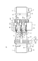
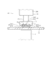
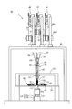
- FIG. 1 is a front view of a wire welding apparatus according to a first embodiment of the present invention.
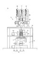
- FIG. 2 is a top view of the wire welding apparatus.
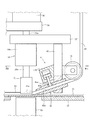
- FIG. 3 is a cross-sectional view taken along line III-III of FIG.
- FIG. 4 is an enlarged view of a portion IV of FIG. 1 showing the periphery of the anvil.
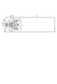
- FIG. 5 is a cross-sectional view taken along the line V-V in FIG. 4 and shows a state in which the end of the electric wire is welded to the sheet-like material.
- FIG. 6 is a top view showing a state in which the electric wires are sequentially welded to the sheet, corresponding to FIG.
- FIG. 7 is a cross-sectional view taken along the line VII-VII in FIG.
- FIG. 6 shows a state in which the electric wire is supplied to the upper surface of the sheet-like material.
- FIG. 8 is a cross-sectional view corresponding to FIG. 7 showing a state in which the electric wire is welded to the sheet-like material.
- FIG. 9 is a top view showing a wire harness obtained by intermittently welding an electric wire to a sheet-like material.
- FIG. 10 is a view corresponding to FIG. 9 and showing a wire harness obtained by continuously welding the electric wire to the sheet-like material.
- FIG. 11 is a top view showing another wire harness including a wire which is bent and welded to a sheet-like material.
- FIG. 12 is an enlarged top view of a portion XII of FIG.
- FIG. 11 shows a state in which the wire is welded to a sheet while curving.
- FIG. 13 is a cross-sectional view corresponding to FIG. 8 showing a state in which a plurality of electric wires having different outer diameters are welded to the sheet-like material.
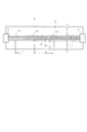
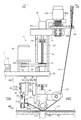
- FIG. 14 is a front view of a wire welding apparatus according to a second embodiment of the present invention.
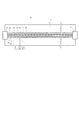
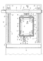
- FIG. 15 is a cross-sectional view taken along line XV-XV of FIG.
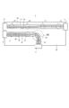
- FIG. 16 is a cross-sectional view taken along line XVI-XVI in FIG.
- FIG. 17 is a cross-sectional view taken along line XVII-XVII in FIG. 16 and shows a frame member.
- FIG. 18 is an enlarged view of a portion XVIII in FIG.
- FIG. 14 shows the periphery of the anvil.
- FIG. 19 is a cross-sectional view taken along line XIX-XIX in FIG. 18, and shows a clamp device and a cutter device.
- FIG. 20 is a cross-sectional view taken along line XX-XX in FIG. 18, and shows a guide member.
- FIG. 21 is a view corresponding to FIG. 18 showing a state where the anvil and the guide member are rotated 90 degrees.
- FIG. 22 is a cross-sectional view taken along the line XXII-XXII in FIG. 18, and shows a state in which the end of the electric wire is welded to the sheet.
- FIG. 23 is a top view showing a state in which the electric wire is continuously and linearly welded to the sheet, corresponding to FIG.
- FIG. 24 is a top view corresponding to FIG. 23, showing a state in which a wire is newly welded across a linear wire.
- FIG. 25 is a top view corresponding to FIG. 24 showing a state in which the electric wire is welded in a U-shape by rotating the anvil by 180 degrees.
- the wire welding apparatus 10 includes a sheet support means 12 for supporting the ultrasonic weldable sheet 11 so that a part or all of the sheet 11 is horizontal.
- the sheet support means 12 supports a part of the elongated sheet-like material 11 so as to be horizontal.
- the sheet supporting means 12 includes a horizontal plate 13 on which a part of the sheet-like material 11 is placed on the upper surface, a pair of winding rollers 14 and 15 provided on both sides of the horizontal plate 13, And a pair of winding motors 16 and 17 for rotating the winding rollers 14 and 15 separately.
- the pair of winding rollers 14 and 15 are provided in parallel to each other, and wind the both sides in the longitudinal direction of the sheet 11 protruding from both ends of the horizontal plate 13.
- the sheet-like material 11 can be welded to another member by the vibration of the ultrasonic horn 51 described later.
- a film made of a resin such as PVC (polyvinyl chloride), PE (polyethylene), PP (polypropylene) or the like, a nonwoven fabric made of these resins, or the like can be used.
- the wire welding device 10 includes a sheet moving unit 21 that moves a part or all of the horizontal portion of the sheet 11 in the horizontal direction.
- the sheet moving means 21 includes a pair of movable rollers 22 and 23 provided in the vicinity of the end on both sides of the horizontal plate 13, and a pair of holding rollers 24 and 25 sandwiching the sheet 11 together with the pair of movable rollers 22 and 23; A pair of drive motors 26, 27 for rotating the pair of movable rollers 22, 23 are provided.
- the sheet-like material 11 protruding from the end of the horizontal plate 13 is placed on the pair of movable rollers 22 and 23.
- the sheet moving unit 21 moves the long sheet 11 in the longitudinal direction by synchronously rotating the pair of movable rollers 22 and 23 at the same speed in the same direction by the pair of drive motors 26 and 27.
- the winding roller 14 or 15 on the rear side in the moving direction of the sheet 11 takes the sheet 11 that has already been wound along with the movement of the sheet 11. Rotate to unroll.
- the winding roller 14 or 15 located forward in the moving direction rotates so as to wind the sheet 11 anew.
- the wire welding device 10 includes an anvil 31 as a pressing tool for pressing the plurality of wires 30 supplied to the upper surface of the sheet 11 from above.
- three electric wires 30 are supplied to the upper surface of the sheet 11 as shown in FIG.
- the number of electric wires 30 is not limited to three, as long as at least one electric wire 30 is supplied to the upper surface of the sheet-like material 11.
- the wire 30 is a so-called insulated wire including a core wire 30 a and an insulating coating 30 b covering the core wire 30 a.
- Core wire 30a is formed of a conductive material such as copper or aluminum.
- the core wire 30a may be a single wire or may be a stranded wire.
- the electric wire 30 is formed on the sheet 11 so as to be capable of ultrasonic welding.
- the insulation coating 30b of the electric wire 30 is made of, for example, ultrasonic weldable resin such as PVC (polyvinyl chloride), PE (polyethylene), PP (polypropylene), etc.
- the insulation coating 30b is a sheet by ultrasonic welding. It is welded to the rod 11.
- the electric wire 30 is formed by extrusion molding.
- the material of the insulating coating 30b is not limited to the resin, and may be a material that can be ultrasonically welded, and may be, for example, a varnish or the like.
- the varnish or the like is applied to the outer periphery of the core wire 30a and baked.
- the rotational moving means 32 includes an upper telescopic actuator 33 as an anvil moving means for moving the anvil 31 in the width direction of the sheet 11 above the horizontal plate 13.
- the upper telescopic actuator 33 includes a ball screw 33 b rotationally driven by a servo motor 33 a and a follower 33 c screwed to the ball screw 33 b.
- the housing 33 d of the upper telescopic actuator 33 is provided above the horizontal plate 13 so as to extend in the width direction of the sheet 11.
- the ball screw 33 b extends in the width direction of the sheet 11, and the follower 33 c moves in the width direction of the sheet 11 by the rotation of the ball screw 33 b.
- a movable plate 34 extending in the longitudinal direction of the sheet 11 is attached to the side of the housing 33 d at the follower 33 c.
- a rotation motor 36 as an anvil rotation means is attached to the movable plate 34 in a state where the rotation shaft 36 a is protruded downward.
- An anvil 31 is attached to the rotation shaft 36a via an intermediate plate 37 and an upper fluid pressure cylinder 38 as lifting means.
- the intermediate plate 37 is provided substantially horizontally.
- the upper hydraulic cylinder 38 comprises a rod 38a which moves relative to the body 38b by the pressure of the fluid.
- the main body 38b is attached to the lower portion of the intermediate plate 37 such that the rod 38a is coaxial with the rotation shaft 36a and extends downward.
- the wire welding apparatus 10 includes a wire supply means 41 for supplying the wire 30 to the upper surface of the sheet-like material 11.
- the wire supply means 41 supplies the wire 30 to the anvil 31 from above.
- the plurality of nozzles 42 of the wire supply means 41 are attached to the intermediate plate 37 in the rotational movement means 32 via the support members 43.
- the nozzle 42 guides the electric wire 30 to the upper surface of the sheet 11.
- the nozzles 42 are provided on the intermediate plate 37 in accordance with the number of the electric wires 30 supplied to the upper surface of the sheet 11. In the present embodiment, since the three electric wires 30 are supplied to the upper surface of the sheet 11, the three nozzles 42 are provided on the intermediate plate 37 as shown in FIG. As shown in FIG. 1, the nozzle 42 is inclined with respect to the horizontal plate 13 so as to guide the electric wire 30 gently from its tip to the top surface of the sheet 11.
- the nozzle 42 is a cylinder having an insertion hole 42 a through which a single electric wire 30 can pass.
- the insertion hole 42 a penetrates the cylindrical body along the central axis of the nozzle 42.
- a notch 42b is formed to penetrate between the outer peripheral surface of the cylindrical body and the inner peripheral surface of the insertion hole 42a.
- the support member 43 supporting the nozzle 42 is provided with a plurality of clamp cylinders 44 as clamp devices capable of inhibiting the movement of the electric wire 30 inserted into the nozzle 42.
- the clamp cylinder 44 includes a rod 44a that moves relative to the main body 44b by fluid pressure.
- the main body 44b is attached to the support member 43 so that the rod 44a is inserted into the notch 42b.
- the clamp cylinder 44 as shown by the solid line, when the rod 44a is extruded from the main body 44b, the rod 44a contacts the electric wire 30 passing through the insertion hole 42a.
- the clamp cylinder 44 prohibits free movement of the electric wire 30.
- a dot-and-dash line when the rod 44a is pulled into the main body 44b, the rod 44a separates from the electric wire 30 passing through the insertion hole 42a.
- the clamp cylinder 44 allows the wire 30 to extend.
- the wire supply means 41 includes a mount 46 provided in the vicinity of the nozzle 42, a plurality of drums 47 provided on the mount 46, and a plurality of supports provided upright on the mount 46. And a plurality of tension devices 48 provided at 46a.
- the electric wire 30 is wound around the drum 47, and the electric wire 30 is stored by the drum 47.
- the tension device 48 applies a predetermined tension to the electric wire 30 unwound from the drum 47 and directed to the nozzle 42.
- the drum 47 and the tension device 48 are provided corresponding to the number of the electric wires 30 supplied. In the present embodiment, three drums 47 and three tension devices 48 are provided to supply three electric wires 30.
- the tension device 48 includes a tension bar 48a rotatably provided about the rotation axis of the rotation support 48b, a wire guide 48c attached to the tension bar 48a, and rotation of the tension bar 48a.
- the elastic member 48d exerts an elastic force according to the movement angle, the potentiometer 48e as a detection means for detecting the rotation angle of the tension bar 48a, and the rotation angle detected by the potentiometer 48e to be a predetermined angle
- a servomotor 48f (FIGS. 2 and 3) as a feeding speed control means for controlling the feeding speed of the electric wire 30.
- a plurality of columns 46a are erected on the gantry 46, and a servomotor 48f and a tension device 48 are provided on the columns 46a.
- the drum 47 is coaxially attached to the rotation shaft of the servomotor 48f.
- the drum 47 is rotated with the rotary shaft.
- the electric wire 30 wound and stored on the drum 47 is unwound and fed out.
- a guide pulley 49 is attached to the intermediate plate 37, and the electric wire 30 which has passed through the wire guide 48 c is guided to the nozzle 42 by the guide pulley 49. That is, the electric wire 30 drawn from the drum 47 is guided to the wire guide 48 c, the guide pulley 49 and the nozzle 42 in the tension device 48, and is supplied to the upper surface of the sheet 11.
- the feeding speed of the electric wire 30 is controlled by the servomotor 48f such that the rotation angle of the tension bar 48a becomes a predetermined angle. Further, the delivery speed of the electric wire 30 is controlled so as to substantially coincide with the moving speed of the sheet-like material 11. A predetermined tension is applied to the electric wire 30 by the tension bar 48a.
- the anvil 31 is attached to the rod 38 a of the upper hydraulic cylinder 38.
- the main body 38b of the upper fluid pressure cylinder 38 is attached to the intermediate plate 37 with the rod 38a directed downward.
- the anvil 31 presses the electric wire 30 supplied to the upper surface of the sheet 11 from above.
- the anvil 31 is formed with a plurality of grooves 31 a having a V-shaped cross section in which the electric wire 30 is inserted.
- the electric wire supply means 41 since three electric wires 30 are supplied from the electric wire supply means 41, three rows of V-shaped grooves 31a in a row are formed in parallel in the anvil 31.
- the V-shaped groove 31 a is formed to correspond to the outer diameter of the wire 30.
- the wire 30 is pressed against the sheet 11 by the anvil 31 by moving the rod 38 a of the upper fluid pressure cylinder 38 downward. In this state, all the electric wires 30 are accommodated in and brought into contact with the corresponding V-shaped groove 31a of the cross section, and pressed against the sheet 11 with an equal force.
- the upper fluid pressure cylinder 38 and the nozzle 42 are provided on the intermediate plate 37, and the intermediate plate 37 is attached to the rotation shaft 36 a of the rotary motor 36. Therefore, when the rotary motor 36 is driven to rotate the intermediate plate 37, the upper fluid pressure cylinder 38 and the nozzle 42 rotate in the horizontal plane (that is, around the vertical axis). Since the anvil 31 is attached to the upper fluid pressure cylinder 38, it rotates with the nozzle 42 in a horizontal plane (i.e., around the vertical axis). Therefore, the direction in which the electric wire 30 is supplied from the nozzle 42 can be changed by the rotary motor 36.
- the rotary motor 36 is moved in the width direction of the sheet 11 by the upper telescopic actuator 33. Therefore, the electric wire 30 has the width of the sheet 11 by moving the nozzle 42 in the width direction of the sheet 11 by the rotary motor 36 and moving the nozzle 42 in the width direction of the sheet 11 by the upper telescopic actuator 33. Supplied in the direction ( Figure 12). That is, in the wire welding device 10, the supply direction of the wire 30 can be made to coincide with the width direction of the sheet 11 as well as the longitudinal direction of the sheet 11.
- an ultrasonic horn 51 is provided to face the anvil 31.
- the ultrasonic horn 51 sandwiches the sheet 11 and the electric wire 30 together with the anvil 31 and welds the sheet 11 to the electric wire 30 by ultrasonic vibration.
- the ultrasonic horn 51 is formed in a size capable of welding three electric wires 30 at one time.
- the electric wire welding apparatus 10 has a horn moving means 52 for moving the ultrasonic horn 51 in the width direction of the sheet 11 and moving it up and down in addition to the sheet moving means 21 for moving the long sheet 11 in the longitudinal direction.
- a horn moving means 52 for moving the ultrasonic horn 51 in the width direction of the sheet 11 and moving it up and down in addition to the sheet moving means 21 for moving the long sheet 11 in the longitudinal direction.
- the horizontal plate 13 is not provided in the range in which the ultrasonic horn 51 moves. Therefore, the ultrasonic horn 51 can be brought into contact with the sheet 11 over the entire movement range of the ultrasonic horn 51.
- the horn moving means 52 includes a lower telescopic actuator 53 for moving the ultrasonic horn 51 in the width direction of the sheet 11 and a lower fluid pressure cylinder 54 as an elevating means for moving the ultrasonic horn 51 up and down.
- the lower telescopic actuator 53 has the same structure as the upper telescopic actuator 33 for moving the anvil 31. That is, the housing 53 d of the lower telescopic actuator 53 is provided to extend in the width direction of the sheet 11 below the horizontal plate 13, and the follower 53 c of the lower telescopic actuator 53 is of the sheet 11. It can move in the width direction.
- the follower 53c protrudes upward from the housing 53d, and the lower fluid pressure cylinder 54 as an elevating means is attached to the follower 53c. Specifically, the main body 54b of the lower fluid pressure cylinder 54 is attached to the follower 53c such that the rod 54a extends upward.
- a vibrator 56 for ultrasonically vibrating the ultrasonic horn 51 is attached to the upper end of the rod 54a, and the ultrasonic horn 51 is provided on the vibrator 56 so as to project upward.
- the lower fluid pressure cylinder 54 (see FIG. 1) of the horn moving means 52 moves the rod 54 a upward with the anvil 31 pressing the electric wire 30 against the upper surface of the sheet 11.
- the ultrasonic horn 51 abuts on the lower surface of the sheet 11 when driven. Therefore, the sheet 11 and the electric wire 30 are held by the anvil 31 and the ultrasonic horn 51.
- the sheet 11 is welded to the electric wire 30 by ultrasonically vibrating the ultrasonic horn 51 in this state.
- the anvil 31 presses the electric wire 30 against the upper surface of the sheet 11 when the upper fluid pressure cylinder 38 of the rotational movement means 32 is driven to move the rod 38 a downward.
- the anvil 31 and the ultrasonic horn 51 can move in the width direction of the sheet 11. Therefore, by moving the anvil 31 and the ultrasonic horn 51 in the width direction, the electric wire 30 (FIGS. 11 and 12) supplied in the width direction of the sheet 11 can be welded to the sheet 11.
- an ultrasonic weldable sheet 11 is prepared, and the sheet support means 12 is used to support the sheet 11 so that a part or all of the sheet 11 is horizontal. Do.
- a part of the sheet 11 is placed on the upper surface of the horizontal plate 13 in the sheet support means 12.
- One side portion of the sheet 11 extending from one end of the horizontal plate 13 is sandwiched by the movable roller 22 and the holding roller 24 of the sheet moving means 21 and the other in the sheet 11 extending from the other end of the horizontal plate 13
- the side portion is pinched by the movable roller 23 of the sheet moving means 21 and the pinch roller 25.
- one end of the sheet 11 is wound around the winding roller 14, and the other end of the sheet 11 is wound around the winding roller 15.
- a part of the elongated sheet-like material 11 is supported on the upper surface of the horizontal plate 13 so as to be horizontal.
- the electric wire 30 to be welded to the sheet 11 is prepared in a state of being wound around the drum 47.
- the drum 47 in which the electric wire 30 is stored is attached to the rotation shaft of the servomotor 48 f in the tension device 48 provided on the support 46 a of the mount 46.
- the electric wire 30 is unwound from the drum 47 and wired to the wire guide 48 c of the tension device 48, and is guided to the nozzle 42 through the guide pulley 49.
- the electric wire 30 is passed through the insertion hole 42 a of the nozzle 42, and the electric wire 30 extended from the nozzle 42 is guided to the V-shaped groove 31 a of the anvil 31.
- the clamp cylinder 44 is used to inhibit the free movement of the electric wire 30. Specifically, the rod 44a of the clamp cylinder 44 is moved downward as shown by a solid line, and the rod 44a is brought into contact with the electric wire 30 passing through the insertion hole 42a.
- the electric wire 30 is welded to the sheet 11. Specifically, the sheet 11 is moved to the welding start position of the electric wire 30 by using the sheet moving means 21 (see FIGS. 1 and 2). As a result, the electric wire 30 can be placed in the vicinity of the end of the sheet 11.
- the movement of the sheet-like material 11 is performed by the sheet moving means 21.
- the pair of movable rollers 22 and 23 are synchronously rotated at the same speed in the same direction by the pair of drive motors 26 and 27 to move the elongated sheet 11 in the longitudinal direction.
- the winding roller 14 or 15 on the rear side in the moving direction of the sheet 11 is a sheet that has already been wound along with the movement of the sheet 11.
- the take-up roller 14 or 15 located in front of the moving direction takes up the sheet 11 anew.
- the upper fluid pressure cylinder 38 in the rotational moving means 32 is driven to move the rod 38 a upward, and the anvil 31 is separated from the electric wire 30.
- the lower fluid pressure cylinder 54 (see FIG. 1) in the horn moving means 52 is driven to move the rod 54 a downward to separate the ultrasonic horn 51 from the lower surface of the sheet 11.
- the sheet moving unit 21 moves the sheet 11 in this state.
- the electric wire 30 and the sheet 11 located in the vicinity of the end of the sheet 11 as shown in FIG. are sandwiched between the ultrasonic horn 51 and the anvil 31, and the sheet 11 is welded to the electric wire 30.
- the rod 38 a of the upper fluid pressure cylinder 38 in the rotational movement means 32 is moved downward, and the electric wire 30 is pressed against the upper surface of the sheet 11 using the anvil 31. Further, the ultrasonic horn 51 is brought into contact with the lower surface of the sheet 11. Thus, the sheet 11 and the electric wire 30 are held by the anvil 31 and the ultrasonic horn 51. In this state, the ultrasonic horn 51 is ultrasonically vibrated.
- a transmission mode of the ultrasonic vibration from the ultrasonic horn 51 there are longitudinal vibration, lateral vibration and the like.
- the transmission mode is appropriately selected according to the shape, physical properties and the like of the member to be welded.
- horn mark 57 when ultrasonic welding is performed, as shown in FIG. 6, a mark (hereinafter referred to as “horn mark 57”) which is pressed against the ultrasonic horn 51 may be left on the member.
- the horn mark 57 since the ultrasonic horn 51 is in contact with the sheet 11, the horn mark 57 remains on the lower surface of the sheet 11 instead of the upper surface of the sheet 11 with which the wire 30 contacts. . For this reason, in the wire welding apparatus 10, it is possible to prevent the wire 30 from being damaged during the ultrasonic welding process.
- the insulating coating 30b of the wire 30 may be deformed.
- the groove 31a of the anvil 31 has a V-shaped cross section, and the width increases from the bottom of the groove 31a toward the opening edge. That is, the groove 31a is a so-called diverging groove. For this reason, when putting the electric wire 30 in the groove 31a, the situation where the insulation coating 30b of the electric wire 30 contacts the corner of the groove 31a and is damaged can be avoided.
- the surface area of the anvil 31 in contact with the insulating coating 30 b of the electric wire 30 in the state where the electric wire 30 enters the groove 31 a is larger than the case where the electric wire 30 contacts the flat surface of the anvil 31. For this reason, even if the wire 30 is pressed against the sheet 11 by the anvil 31, excessive deformation of the insulating coating 30b of the wire 30 can be avoided. Therefore, it becomes possible to control modification of electric wire 30 resulting from welding.
- the clamp cylinder 44 is used to allow free movement of the electric wire 30 in the insertion hole 42 a of the nozzle 42. Specifically, as shown by a dot-and-dash line in FIG. 4, the rod 44 a of the clamp cylinder 44 is moved upward to separate the rod 44 a from the electric wire 30.
- the sheet 11 is moved again by a predetermined amount.
- the electric wire 30 is newly fed out from the nozzle 42 with the movement of the sheet 11.
- the wire 30, which has been newly fed out is welded to the sheet 11 again.
- the rod 38 a of the upper fluid pressure cylinder 38 in the rotational movement means 32 is moved upward to separate the anvil 31 from the electric wire 30 and the ultrasonic horn 51 from the lower surface of the sheet 11 Let them separate. As a result, the sheet 11 and the electric wire 30 are not held by the anvil 31 and the ultrasonic horn 51. Thereafter, the pair of movable rollers 22 and 23 are synchronized again and rotated at the same speed in the same direction by the pair of drive motors 26 and 27 shown in FIG. 1 to locate the elongated sheet 11 in the longitudinal direction. Move it quantitatively.
- the end of the electric wire 30 welded to the sheet 11 moves away from the nozzle 42. Therefore, the electric wire 30 is newly supplied from the nozzle 42 to the upper surface of the sheet 11.
- the wire 30 and the sheet-like material 11 which are newly fed out are nipped again by the ultrasonic horn 51 and the anvil 31. Thereafter, the ultrasonic horn 51 is ultrasonically vibrated again to weld the sheet 11 to the electric wire 30.
- the moving step of moving the sheet 11 by a predetermined amount and the electric wire 30 newly fed out from the nozzle 42 are made into the sheet 11 again.
- the movement and welding of the sheet-like material 11 are repeated a predetermined number of times, and the wires 30 of a desired length and number are welded to the relatively long sheet-like material 11 while avoiding damage to the wires 30.
- the range of one welding portion and the predetermined amount of movement of the sheet-like material 11 in each moving step are appropriately set according to the required bonding strength and the like.
- the predetermined amount of movement of the sheet-like material 11 corresponds to the interval (pitch P) between adjacent welding points.
- the pitch P may not be constant. That is, the electric wire 30 may be intermittently welded to the sheet 11 at a constant pitch P along the longitudinal direction of the electric wire 30 with a constant movement amount of the sheet 11 at each movement step, or the movement step
- the wire 30 may be welded to the sheet 11 at different pitches P by changing the amount of movement of the sheet 11 at each time.
- the clamp cylinder 44 is used to inhibit the movement of the wires 30 in the nozzle 42. Specifically, as shown by a solid line in FIG. 4, the rod 44 a of the clamp cylinder 44 is moved downward, and the rod 44 a is brought into contact with the electric wire 30 inserted into the insertion hole 42 a of the nozzle 42. In that state, the electric wire 30 is cut at a position between the nozzle 42 and the portion welded to the sheet 11. Thereafter, the sheet-like material 11 to which the electric wire 30 is welded is removed from the sheet support means 12 (see FIG. 1). Thus, a relatively long wire harness 9 (see FIG. 9) is obtained in which the wires 30 of desired length and number are welded to the relatively long sheet 11.
- the connector 8 is then attached to the end of the wire 30 as necessary in the wire harness 9 obtained by intermittently welding the wire 30 to the sheet 11 as described above. And transported to an automobile assembly line or the like.
- the wire harness 9 is laid along a fixing material such as a lining material of the car, and the sheet 11 is welded to the fixing material at a required position using an ultrasonic welding tool. Ru.
- FIG. 9 shows a wire harness 9 formed by intermittently welding the electric wire 30 to the sheet 11.
- the wire harness 9 shown in FIG. 9 is obtained by making the moving amount (pitch P) of the sheet-like material 11 in each moving step larger than the outer diameter of the ultrasonic horn 51.
- the electric wire 30 may be continuously welded to the sheet 11.
- the wire harness 9 shown in FIG. 10 is obtained by making the moving amount (pitch P) of the sheet-like material 11 in each moving step equal to or less than the outer diameter of the ultrasonic horn 51 corresponding to the ultrasonic welding range.
- the ultrasonic horn 51 is brought into contact with the sheet 11 instead of the electric wire 30 in the electric wire welding apparatus 10. Therefore, the wire 30 can be welded to the sheet 11 while avoiding damage to the wire 30.
- the three electric wires 30 are welded so as to extend in parallel in the longitudinal direction of the sheet 11 in parallel.
- the wires 30 may be newly welded to the sheet 11 so as to be aligned with the wires 30 already welded.
- the wire harness 9 shown in FIG. 11 welds the sheet-like material 11 using a pair of winding motors 16 and 17 (see FIG. 1) of the sheet support means 12 after welding three electric wires 30 to the sheet-like material 11. It is obtained by welding the new electric wire 30 back to the sheet 11.
- the anvil 31 and the nozzle 42 are provided on the intermediate plate 37 via the upper fluid pressure cylinder 38 and the support member 43, respectively, and the intermediate plate 37 is attached to the rotation shaft 36a of the rotary motor 36. . Therefore, both the anvil 31 and the nozzle 42 rotate in the horizontal plane (that is, around the vertical axis).
- the rotary motor 36 is configured to move in the width direction of the sheet 11 by the upper telescopic actuator 33. Therefore, the width of the sheet 30 from the nozzle 42 is obtained by moving the nozzle 42 along with the rotary motor 36 in the width direction so that the supply direction of the wire 30 from the nozzle 42 substantially matches the width direction of the sheet 11. It is possible to supply along the direction.
- the ultrasonic horn 51 is configured to move in the width direction of the sheet 11. Therefore, by moving the ultrasonic horn 51 in the width direction of the sheet 11 while facing the anvil 31, the electric wire 30 supplied along the width direction of the sheet 11 is made of the sheet 11. It can be welded to the sheet 11 while extending in the width direction.
- the anvil 31 is rotatable in a plane parallel to the sheet 11 (i.e., about a vertical axis). Therefore, welding can be performed in a state in which the plurality of electric wires 30 supplied in parallel are arranged in parallel along the longitudinal direction and the width direction of the sheet-like object 11.
- the wire 30 is moved from the nozzle 42 in the width direction of the sheet 11 by moving the nozzle 42 in the width direction of the sheet 11 after the wiring direction of the wire 30 is changed in the width direction of the sheet 11. Supplied.
- a plurality of electric wires 30 supplied in parallel are welded to the sheet 11 while moving the ultrasonic horn 51 in the width direction of the sheet 11 with the movement of the nozzle 42. Accordingly, welding can be performed not only in the longitudinal direction of the sheet-like product 11 but also in the width direction in a state where the plurality of electric wires 30 are arranged in parallel. As a result, the degree of freedom in the arrangement of the wires 30 is improved.
- a plurality of nozzles 42 through which a single electric wire 30 is inserted is provided.
- a single nozzle 42 through which the plurality of electric wires 30 can be inserted may be used.
- the outer diameters of the three electric wires 30 are substantially equal, and the sizes of the three grooves 31 a of the anvil 31 are substantially equal.
- the outer diameters of the three wires 30 may be different.
- the anvil 31 may be formed so that all the electric wires 30 are accommodated in and brought into contact with the corresponding V-shaped groove 31 a in a state where the electric wires 30 are pressed against the sheet 11. Further, the groove 31a may be formed so as to press the plurality of electric wires 30 on the sheet 11 with an equal force.
- FIGS. 14 to 25 show a wire welding apparatus 60.
- FIG. 16 show a wire welding apparatus 60.
- the wire welding device 60 includes a sheet support means 62.
- the sheet support means 62 supports the entire ultrasonic weldable sheet 11 so that it is horizontal.
- the sheet support means 62 includes a frame member 64 for supporting the outer periphery of the sheet-like material 11.
- the sheet 11 is formed in a rectangular shape.
- the frame member 64 is formed to hold the periphery of the rectangular sheet 11.
- the frame member 64 includes a flat metal plate 65 having an opening at its center, a reinforcing member 66 for reinforcing the periphery of the flat plate 65, and the sheet 11 placed on the flat plate 65.
- a presser 67 for pressing the four corners of the plate toward the flat plate member 65.
- the flat plate member 65 is formed by combining a plurality of long long plates 65 a in a rectangular shape along the outer shape of the sheet-like object 11.
- the flat plate 65 is made of metal.
- the presser 67 includes a flat plate 65 and a presser plate 67 a sandwiching the periphery of the sheet 11.
- a magnet 67b is provided on the pressing plate 67a. Therefore, in a state where the edge of the sheet 11 is placed on the flat plate 65, the edge of the sheet 11 is flat plate 65 by the magnetic force of the magnet 67b by overlapping the pressing member 67 on the edge of the sheet 11. And the pressing plate 67a.
- a handle 67c is provided on the pressing plate 67a. When the worker grips the handle 67c and pulls the presser 67 away from the flat plate 65 against the force attracted to the flat plate 65 of the magnet 67b, the sheet 11 can be removed from the frame member 64.
- the sheet support means 62 includes a horizontal plate 63 on which the frame member 64 is mounted.
- the frame member 64 supports the entire sheet 11 so as to be horizontal while being placed on the horizontal plate 63.
- the wire welding device 60 includes a sheet moving means 71 for moving the frame member 64 placed on the upper surface of the horizontal plate 63 in the horizontal direction.
- the sheet moving means 71 moves the frame member 64 both in the longitudinal direction and in the width direction (short direction) of the flat plate member 65, that is, in all directions in the horizontal direction. In a state where the periphery of the sheet 11 is sandwiched by the frame member 64 and the frame member 64 is placed on the horizontal plate 63, the entire sheet 11 becomes horizontal. Therefore, by moving the frame member 64 horizontally, the sheet moving means 71 moves the entire horizontal portion of the sheet 11 in either the longitudinal direction or the width direction (short direction) of the sheet 11. That is, it moves in all directions in the horizontal direction.
- the sheet moving means 71 includes a width direction actuator 72 for moving the frame member 64 in the width direction of the sheet 11 and a pair of longitudinal actuators for moving the width direction actuator 72 in the longitudinal direction of the sheet 11 together with the frame member 64. And 73.
- the actuators 72 and 73 have the same structure as the extension actuator 33 (see FIGS. 1 and 2 etc.) in the first embodiment.
- the pair of longitudinal actuators 73 are provided on both sides of the horizontal plate 63 of a size sufficient to move the frame member 64 so as to sandwich the central portion of the horizontal plate 63 from both sides. That is, the housing 73 d of the longitudinal actuator 73 is provided in parallel to the longitudinal direction of the sheet 11.
- the housing 72d of the width direction actuator 72 is bridged by a pair of followers 73c which move in the longitudinal direction by the rotation of the ball screw 73b by the servomotor 73a.
- the width direction actuator 72 is provided with a follower 72c which is moved by the rotation of the ball screw 72b by the servomotor 72a.
- the follower 72 c is provided with a locking member 74 that locks to the locking plate 68 of the frame member 64.
- the frame member 64 includes a reinforcing member 66 for reinforcing the short side of the flat plate member 65 assembled in a rectangular shape, and the locking plate 68 is provided on the reinforcing member 66.
- the locking member 74 is attached to the locking plate 68 of the frame member 64 in a state where the frame member 64 is placed on the horizontal plate 63, and locks to the frame member 64.
- the sheet moving means 71 when the servomotor 72a of the width direction actuator 72 is driven, the ball screw 72b rotates and the follower 72c moves in the width direction. Since the follower 72c is locked to the frame member 64 via the locking member 74, the frame member 64 moves in the width direction together with the supported sheet 11 as the follower 72c moves. Further, in the sheet moving means 71, when the servomotors 73a of the pair of longitudinal actuators 73 are simultaneously driven, the pair of ball screws 73b rotate synchronously and the pair of followers 73c move at the same speed in the same direction. Do.
- the width direction actuator 72 Since the housing 72d of the width direction actuator 72 is bridged by the pair of followers 73c, the width direction actuator 72 is supported by the frame member 64 mounted on the horizontal plate 63 with the movement of the pair of followers 73c. The sheet 11 moves in the longitudinal direction with the sheet 11.
- the wire welding device 60 rotates the anvil 81 provided above the sheet 11 and the anvil 81 in a horizontal plane (that is, around the vertical axis) and vertically raises and lowers it.
- rotational movement means 82 The anvil 81 presses the electric wire 30 supplied to the upper surface of the sheet 11 from above.
- a cross beam member 83 extending in the width direction above the horizontal plate 63 is provided substantially at the center of the horizontal plate 63 in the longitudinal direction, and a support plate 84 extends in the longitudinal direction at the approximate center of the cross beam member 83 in the width direction. It is provided as it exists.
- the anvil 81 is supported by the support plate 84 via the rotational movement means 82.
- a rotary motor 86 for rotating the anvil 81 in a horizontal plane is attached to the support plate 84 in a state in which its rotation shaft 86 a protrudes downward.
- a vertical rotary rod 87 is provided on the support plate 84 so as to be rotatable about the vertical axis and movable in the vertical direction.
- a boss material 85 that surrounds the vertical rotary bar 87 is attached upward, and a horizontal member 89 is provided on the upper end of the boss material 85.
- the horizontal member 89 is provided substantially horizontally, and the horizontal member 89 is provided with a fluid pressure cylinder 88 as elevating means for raising and lowering the anvil 81 in the vertical direction.
- the fluid pressure cylinder 88 includes a rod 88a that moves relative to the body 88b by the pressure of the fluid.
- the body 88b is attached to the horizontal member 89 such that the rod 88a is coaxial with the vertical rod 87 and extends downwardly.
- the upper end of the vertical rotary bar 87 is rotatably engaged with the lower end of the rod 88a.
- the vertical rotary bar 87 passes through the support plate 84, and the anvil 81 is attached to the lower end of the vertical rotary bar 87 via the pivot support 94.
- the support plate 84 is provided with a pulley 91 which is non-rotatable with respect to the vertical rotary bar 87 and movable in the vertical direction with respect to the vertical rotary bar 87.
- a pulley 92 is provided on a rotary shaft 86 a of the rotary motor 86, and a belt 93 is bridged between the pulley 92 and the pulley 91.
- the wire welding device 60 includes a wire supply means 41.
- the anvil 81 is pivotally supported about a horizontal axis by a pivot support 94 attached to the lower end of the vertical rotary bar 87.
- a plurality of pulley-like wire guides 102 for turning the electric wire 30 led from above by the electric wire supply means 41 are further pivoted.
- the wire guides 102 are provided corresponding to the number of wires 30 required.
- the pivot support 94 supporting the wire rod guide 102 and the anvil 81 is provided with a clamp cylinder 104 as a clamp device and a cutter cylinder 106 as a cutter device via fluid pressure cylinders 96 and 97. .
- the clamp cylinder 104 turns the wire rod guide 102 to clamp the wire 30 which has passed through the anvil 81.
- the main body portion 96 b of the vertical fluid pressure cylinder 96 is provided on the opposite side of the wire guide 102 with the anvil 81 interposed therebetween.
- the movable piece 96a of the vertical direction fluid pressure cylinder 96 moves in the vertical direction with respect to the main body 96b.
- the movable piece 96 a of the vertical fluid pressure cylinder 96 is provided with a main body 97 b of the horizontal fluid pressure cylinder 97.
- the movable piece 97 a of the horizontal fluid pressure cylinder 97 moves relative to the main body 97 b in the horizontal direction orthogonal to the electric wire 30 passing through the anvil 81, that is, in the direction along the rotation axis of the anvil 81.
- a mounting piece 98 is attached to the movable piece 97a of the horizontal fluid pressure cylinder 97 so as to extend in the vertical direction.
- a clamp 105a is attached to the attachment piece 98, and the electric wire 30 which has passed through the anvil 81 is placed on the clamp 105a.
- the fixed cutter blade 107a is attached to the mounting piece 98, and the electric wire 30 is placed on the fixed cutter blade 107a.
- a clamp cylinder 104 and a cutter cylinder 106 are provided on the mounting piece 98.
- the clamp cylinder 104 is a fluid pressure cylinder, and includes a rod 104a that moves relative to the main body 104b by fluid pressure.
- the clamping piece 105b is attached to the rod 104a of the clamp cylinder 104, and the electric wire 30 is clamped by the clamping tool 105a and the clamping piece 105b.
- the main body 104b of the clamp cylinder 104 is attached to the mounting piece 98 so that the wire 30 is held between the holding tool 105 and the holding piece 105b when the holding piece 105b moves with the rod 104a by moving the rod 104a downward. It is attached.
- the clamp cylinder 104 prohibits free movement of the electric wire 30 by moving the rod 104 a in the direction indicated by the solid line arrow to hold the electric wire 30. Further, the clamp cylinder 104 allows the wire 30 to extend by moving the rod 104 a in the direction indicated by the broken line arrow to cancel the clamping of the wire 30.
- the cutter cylinder 106 is a fluid pressure cylinder, and includes a rod 106 a that moves relative to the main body 106 b by fluid pressure.
- the cutter cylinder 106 cuts the electric wire 30 which has passed through the clamp cylinder 104 in the vicinity of the clamp cylinder 104.
- a movable cutter blade 107b is attached to the rod 106a of the cutter cylinder 106 to cut the electric wire 30 in cooperation with the fixed cutter blade 107a.
- the main body 106b of the cutter cylinder 106 is attached to the mounting piece 98 such that the cutting edge of the movable cutter blade 107b abuts on the cutting edge of the fixed cutter blade 107a. Therefore, when the rod 106a moves downward with the movable cutter blade 107b, the electric wire 30 existing between the movable cutter blade 107b and the fixed cutter blade 107a is cut. As described above, the cutter cylinder 106 cuts the electric wire 30 by moving the rod 106 a in the direction indicated by the solid arrow.
- the anvil 81 is a roller pivotally supported by the pivot support 94, and can roll on the top surface of the sheet 11.
- the anvil 81 presses the electric wire 30 supplied from above and deflected by the wire guide 102 against the sheet 11.
- a groove 81 a having a U-shaped cross section in which the electric wire 30 is inserted is formed around the roller-shaped anvil 81.
- the three electric wires 30 are supplied by being deflected by the wire guide 102, three rows of U-shaped grooves 81a are formed in parallel to each other in the anvil 81.
- the U-shaped groove 81 a of the anvil 81 is formed to correspond to the outer diameter of the wire 30.
- the anvil 81 presses the wires 30 against the sheet 11 all the wires 30 are accommodated in and brought into contact with the corresponding U-shaped groove 81a of the cross section, and pressed against the sheet 11 with an equal force.
- the wire supply means 41 supplies the wire 30 to the anvil 81 from above.
- a fluid pressure cylinder 88 is provided on the horizontal member 89 above the anvil 81.
- the horizontal member 89 includes a guide member 108 for guiding the electric wire 30 to the wire rod guide 102 and a guide member rotation means for rotating the guide member 108 synchronously with the rotation of the anvil 81 in the horizontal plane (that is, rotation around the vertical axis).
- the electric motor 109 is further provided.
- the electric wire 30 is supplied to the anvil 81 through the guide member 108 and the wire guide 102.
- the guide member 108 is formed in a flat plate shape.
- a passage hole 108 a is formed at the distal end of the guide member 108, and the proximal end is pivotally supported by the horizontal member 89.
- the electric motor 109 rotates the guide member 108.
- the electric motor 109 is attached to the horizontal member 89 such that the rotation shaft 109 a is coaxial with the pivot point of the guide member 108.
- the rotating shaft 109a is coaxially attached to the proximal end of the guide member 108 (FIG. 18).
- the anvil 81 presses the wire 30 against the top surface of the sheet 11.
- the anvil 81 is provided on the pivot support 94, and is rotated in the horizontal plane (that is, around the vertical axis) by the drive of the rotary motor 86.
- the electric motor 109 is driven to turn the guiding member 108 in the same direction even if it is rotated.
- the passage hole 108a of 108 moves. Then, the guide member 108 guides the electric wire 30 which is fed from above and passes through the passage hole 108 a to the wire guide 102.
- the supply direction of the electric wire 30 from the wire guide 102 also faces in the width direction of the sheet 11.
- the electric wire 30 supplied from the wire guide 102 can be supplied also in the width direction (FIG. 24). That is, in the wire welding device 60, the wire 30 can be supplied not only in the longitudinal direction of the sheet 11 but also in the width direction.
- the electric motor 109 rotates the guide member 108 in the same direction in synchronization with the rotation of the anvil 81 in the horizontal plane (that is, the rotation around the vertical axis). Therefore, the electric wire 30 drawn from above is promptly guided to the wire guide 102 rotating with the anvil 81 without any problem.
- the ultrasonic horn 111 is provided below the anvil 81 so as to face the anvil 81.
- the ultrasonic horn 111 sandwiches the sheet 11 and the electric wire 30 together with the anvil 81 (FIGS. 18 and 21) and welds the sheet 11 to the electric wire 30 by ultrasonic vibration.
- the three electric wires 30 are supplied, the three electric wires 30 are formed in a size that can be welded at one time.
- a hole 63a slightly larger than the outer diameter of the ultrasonic horn 111 is formed in the horizontal plate 63 below the anvil 81.
- the ultrasonic horn 111 is configured to be able to move up and down, and the upper end of the ultrasonic horn 111 is inserted through the hole 63a when rising.
- the wire welding device 60 includes a lower fluid pressure cylinder 112 as an elevating means for raising and lowering the ultrasonic horn 111.
- the main body 112b of the lower fluid pressure cylinder 112 is mounted below the hole 63a with the rod 112a facing upward.
- a vibrator 110 for ultrasonically vibrating the ultrasonic horn 111 is attached to the upper end of the rod 112 a, and the ultrasonic horn 111 is provided to project upward from the vibrator 110.
- the ultrasonic horn 111 attached to the upper end of the rod 112a is lowered.
- the upper edge of the ultrasonic horn 111 is flush with the upper surface of the horizontal plate 63. Therefore, when the ultrasonic horn 111 is lowered, the interference between the frame member 64 (FIG. 16) mounted on the upper surface of the horizontal plate 63 and the ultrasonic horn 111 can be prevented. This enables horizontal movement of the frame member 64 (FIG. 16) mounted on the upper surface of the horizontal plate 63.
- the ultrasonic weldable sheet 11 is prepared, and the sheet support means 62 is used to support the sheet 11 so that a part or all of the sheet 11 is horizontal.
- the sheet support means 62 includes a frame member 64.
- a frame member 64 capable of supporting the sheet-like material 11 of a necessary size is prepared, and the sheet-like material 11 is supported using the frame member 64.
- the edge of the sheet-like object 11 is placed on the flat plate member 65 of the frame member 64, and in this state, the presser 67 is superimposed on the edge of the sheet-like object 11.
- the frame member 64 After supporting the sheet 11 with the frame member 64, the frame member 64 is placed on the horizontal plate 63. Thereby, the sheet-like object 11 can be supported so that the whole becomes horizontal.
- the locking plate 68 provided on the frame member 64 is locked to the locking member 74 in the sheet moving means 71. Thereby, the movement of the frame member 64 in the horizontal plane by the sheet moving means 71 becomes possible.
- the electric wire 30 to be welded to the sheet 11 is unwound from the stored drum 47 and wired to the wire guide 48c of the tension device 48 and passed through the hole 108a of the guide member 108 Guide to the guide 102.
- the wire guide 102 turns the electric wire 30 and guides it to the U-shaped groove 81 a (FIG. 21) of the anvil 81. Thereafter, the electric wire 30 which has passed through the anvil 81 is clamped by the clamp cylinder 104. Thereby, the free movement of the electric wire 30 can be prohibited.
- the sheet moving unit 71 is used to move the sheet 11 to the welding start position of the electric wire 30. Thereby, as shown in FIG. 22, it becomes possible to place the electric wire 30 in the vicinity of the end portion of the sheet 11. That is, the sheet moving means 71 (FIG. 16) moves the frame member 64 placed on the horizontal plate 63 together with the sheet 11, and the electric wire 30 near the end of the sheet 11 supported by the frame 64. Move relatively.
- the fluid pressure cylinder 88 shown in FIG. 18 is driven so that the rod 88 a enters the main body 88 b and the anvil 81 is separated from the sheet 11.
- the lower fluid pressure cylinder 112 shown in FIG. 14 is driven so that the rod 112a enters the main body 112b, and the ultrasonic horn 111 is separated from the lower surface of the sheet-like material 11.
- the sheet moving means 71 moves the sheet 11 in this state.
- the rod 88 a of the fluid pressure cylinder 88 shown in FIG. 18 is moved downward, and the electric wire 30 is pressed against the upper surface of the sheet 11 using the anvil 81. Further, the rod 112 a of the lower fluid pressure cylinder 112 shown in FIG. 14 is moved upward, and the ultrasonic horn 111 is brought into contact with the lower surface of the sheet 11. Thus, the sheet 11 and the electric wire 30 are held by the anvil 81 and the ultrasonic horn 111. In this state, the ultrasonic horn 111 is ultrasonically vibrated to weld the sheet 11 to the electric wire 30.
- the sheet 11 is moved in a state in which the ultrasonic horn 111 is ultrasonically vibrated.
- the wire 30 is newly fed out from the wire guide 102.
- the wire 30 which is fed out anew is held by the roller-shaped anvil 81 rolling on the sheet 11 and the ultrasonic horn 111 one after another, and is sequentially welded to the upper surface of the sheet 11.
- the electric wire 30 is continuously welded in the moving direction of the sheet 11.
- the sheet-like material 11 slides on the upper end edge of the ultrasonic horn 111, and the roller-like anvil 81 rolls on the sheet-like material 11.
- the wire 30 drawn out on the sheet 11 is sequentially welded to the sheet 11 at a stage where it is held between the anvil 81 and the ultrasonic horn.
- the wires 30 are welded to the sheet 11 continuously.
- the ultrasonic horn 111 is in contact with the sheet 11 from below. Therefore, the horn marks 57 are generated on the lower surface of the sheet 11.
- the anvil 81 rolls on the upper surface of the sheet 11. Therefore, the electric wire 30 welded to the upper surface of the sheet 11 is not damaged like a sliding mark of the anvil 81.
- the groove 81a formed in the anvil 81 has a U-shaped cross section. Therefore, the surface area of the anvil 81 in contact with the insulating coating 30 b (see FIG. 7) of the wire 30 is larger than that in the case where the wire 30 contacts the flat surface of the anvil 81. Therefore, even if the wire 30 is pressed against the sheet 11 by the anvil 81, excessive deformation of the insulating coating 30b of the wire 30 can be avoided. Therefore, it becomes possible to control modification of electric wire 30 resulting from welding.
- the pivot support 94 provided with the anvil 81 is rotated in the horizontal plane (that is, around the vertical axis) by the rotary motor 86 shown in FIG.
- the sheet moving means 71 shown in FIG. 16 moves the frame member 64 supporting the sheet 11 not only in the longitudinal direction but also in the width direction. Therefore, as shown in FIG. 21, the rolling direction of the roller-shaped anvil 81 is directed in the width direction of the sheet 11, and the sheet 11 is moved in the width direction, as shown in FIG.
- the electric wire 30 supplied from the guide 102 can be disposed in the width direction of the sheet 11. Since the anvil 81 rolls and clamps the electric wire 30 together with the ultrasonic horn 111, the electric wire 30 can be welded continuously in the width direction of the sheet 11.
- the anvil 81 is formed with a plurality of rows of grooves 81a in which a plurality of electric wires 30 supplied in parallel are inserted. Therefore, it becomes possible to weld the electric wires 30 in parallel in the longitudinal direction and the width direction of the sheet-like material 11.
- the anvil 81 is gradually rotated with the wire guide 102, and the plural electric wires 30 supplied in parallel are kept parallel to the sheet 11. Weld. Thereby, the wiring direction can be changed from the longitudinal direction of the sheet-like object 11 to the width direction, with the plurality of electric wires 30 being arranged in parallel.
- the wire welding device 60 also includes a fluid pressure cylinder 88 that raises and lowers the anvil 81. Therefore, when crossing the electric wire 30 continuously welded in the width direction of the sheet 11 with another electric wire 30 continuously welded in the longitudinal direction of the sheet 11 first, the anvil 81 ascends once Then, the anvil 81 can be floated from the upper surface of the sheet-like object 11, and the electric wire 30 can be straddled by another electric wire 30. Thereby, it is possible to prevent the anvil 81 from rolling so as to cross over another electric wire 30 which is previously welded continuously in the longitudinal direction of the sheet-like object 11.
- the anvil 81 exceeds the other electric wire 30 continuously welded in the longitudinal direction of the sheet 11 earlier, the anvil 81 is lowered again and rolled on the sheet 11 to obtain the tip.
- the wire 30 is newly crossed with another wire 30 without causing damage due to the rolling of the anvil 81. It can be made to weld continuously in the width direction of 11.
- the rotation range i.e., the rotation range around the vertical axis
- the pivot support 94 is rotated 90 degrees in the horizontal plane (that is, around the vertical axis) to arrange the plurality of electric wires 30. It is also possible to change the drawing direction from the longitudinal direction of the sheet 11 to the width direction and further rotate the pivot support 94 by 90 degrees to return the arranging direction to the longitudinal direction of the sheet 11. In this case, the plurality of electric wires 30 are welded in a U-shape to the sheet 11 while being arranged in parallel.
- the electric motor 109 rotates the guide member 108 in the same direction in synchronization with the rotation of the anvil 81 in the horizontal plane (that is, the rotation around the vertical axis). Therefore, even if the wire guide 102 is rotated by 180 degrees together with the anvil 81, the guide member 108 promptly guides the wire 30 fed from above to the wire guide 102 without any problem. Therefore, there is no problem in welding the electric wire 30 to the sheet 11 in a U-shape. As a result, the degree of freedom in the arrangement of the wires 30 is further improved.
- the clamp cylinder 104 shown in FIG. 18 clamps the wires 30 extending from the roller anvil 81 to the sheet 11. . Thereby, supply of the new electric wire 30 can be stopped. In that state, the electric wire 30 is cut by the cutter cylinder 106 at a position between the clamp cylinder 104 and the portion welded to the sheet 11. Thereafter, the frame member 64 is removed from the sheet moving means 71 together with the sheet-like object 11 to which the electric wire 30 is welded. Then, by further removing the sheet-like material 11 from the frame member 64 of the sheet support means 62, a wire harness in which the wires 30 of desired length and number are welded to the sheet-like material 11 can be obtained.
- the electric wire 30 extending from the anvil 81 is clamped by the clamp cylinder 104. Therefore, by attaching another frame member 64 on which the sheet-like object 11 is supported to the sheet moving means 71, it is possible to immediately start the welding work of the next electric wire 30 to the sheet-like object 11.
- the wire harness obtained by ultrasonic welding of the electric wire 30 continuously to the sheet 11 is then connected to the end of the electric wire 30 as needed as in the first embodiment described above.
- the sheet 11 is laid along a fixing material such as a lining material of a car, and the sheet 11 is welded and fixed to the fixing material at a required position using an ultrasonic welding tool.
- the wire welding apparatus 10, 60 supplies the wire 30 to the sheet support means 12, 62 for supporting the ultrasonic weldable sheet 11 so that a part or all of the sheet 11 is horizontal and the upper surface of the sheet 11.
- ultrasonic horns 51 and 111 configured to be capable of holding the sheet-like material 11 and the electric wire 30.
- the wire welding apparatus 10, 60 preferably includes sheet moving means 21, 71 for moving a horizontal part or all of the sheet 11 in the horizontal direction.
- the wire welding device 10 is orthogonal to the moving direction of the sheet-like material 11 It is preferable to further include an upper telescopic actuator 33 for moving the anvil 31 in the direction, and a horn moving means 52 for moving the ultrasonic horn 51 in the direction orthogonal to the moving direction of the sheet-like material 11.
- the anvil 81 may be a roller that can roll on the upper surface of the sheet 11 while pressing the electric wire 30 against the sheet 11. Grooves 31a and 81a into which the electric wire 30 is inserted may be formed in the anvils 31 and 81, respectively.
- the wire welding apparatus 10, 60 may further include rotary motors 36, 86 for rotating the anvils 31, 81 in a horizontal plane (ie, around the vertical axis).
- the wire welding apparatus 60 When the wire supply means 41 supplies the wire 30 to the anvil 81 from the upper side, the wire welding apparatus 60 is provided above the anvil 81 and guides the guide member 108 for guiding the wire 30 supplied to the anvil 81;
- the electric motor 109 may be further provided to rotate in synchronization with the rotation of the anvil 81 in the horizontal plane (that is, the rotation about the vertical axis).
- the ultrasonic horns 51, 111 are in contact with the lower surface of the sheet 11 supplied with the electric wire 30 on the upper surface, the ultrasonic horns 51, 111 are in contact with the lower surface of the sheet 11
- the electric wire 30 can be welded to the sheet 11 by ultrasonic vibration.
- a contact mark is generated at a portion where the ultrasonic horns 51 and 111 are in contact.
- the wire welding apparatus 10, 60 since the ultrasonic horns 51, 111 are brought into contact with the sheet 11, even if a contact mark is generated on the sheet 11, the contact mark of the ultrasonic horns 51, 111 is displayed on the electric wire 30. There is nothing to happen. Therefore, it can be avoided that the electric wire 30 is damaged due to the contact of the ultrasonic horns 51 and 111, and the electric wire 30 is welded to the sheet 11 while avoiding the damage of the electric wire 30. Is possible.
- the electric wire 30 can be welded to the relatively long sheet 11, and the relative A long wire harness can be obtained.
- the electric wire 30 can be welded in the width direction of the sheet 11.
- anvil 81 is formed of a rollable roller on the upper surface of the sheet 11, continuous welding of the electric wire 30 is facilitated.
- the grooves 31 a and 81 a into which the wires 30 enter it is possible to suppress the deformation of the wires 30 caused by being pressed against the sheet-like material 11.
- the anvils 31, 81 can be rotated in a plane parallel to the sheet 11 (that is, around the axis orthogonal to the sheet 11), the plurality of electric wires 30 supplied in parallel will be the sheet 11 It becomes possible to weld in parallel with each other in the longitudinal direction and width direction, and it is possible to improve the degree of freedom in the arrangement of the wires 30.
- the lifting and lowering means for lifting and lowering the anvils 31 and 81 is the fluid pressure cylinders 38 and 88
- the raising and lowering means is not limited to the fluid pressure cylinder as long as the anvils 31 and 81 can be raised and lowered.
- the anvils 31 and 81 may be raised and lowered using a cam mechanism.
- the number of electric wires 30 is not limited to this, and may be one, two, or four or more.
Landscapes
- Engineering & Computer Science (AREA)
- Mechanical Engineering (AREA)
- Manufacturing & Machinery (AREA)
- Manufacturing Of Electrical Connectors (AREA)
- Pressure Welding/Diffusion-Bonding (AREA)
Abstract
L'invention concerne un dispositif de soudage de fil électrique (10, 60) comprenant : un moyen de support de feuille (12, 62) pour supporter un objet en feuille soudable par ultrasons (11) de telle sorte que l'objet en feuille soudable par ultrasons (11) devient partiellement ou entièrement horizontal; un moyen d'alimentation en fil électrique (41) pour fournir un fil électrique (30) sur une surface supérieure de l'objet en feuille (11); une enclume (31, 81) pour pousser, depuis le haut, le fil électrique (30) fourni sur la surface supérieure de l'objet en feuille (11); et un émetteur d'ultrasons (51, 111) qui est disposé sur une surface inférieure de l'objet en feuille (11) de façon à s'opposer à l'enclume (31, 81), et qui prend en sandwich l'objet en feuille (11) et le fil électrique (30) entre l'émetteur d'ultrasons (51, 111) et l'enclume (31, 81).
Priority Applications (2)
| Application Number | Priority Date | Filing Date | Title |
|---|---|---|---|
| DE112018002834.8T DE112018002834B4 (de) | 2017-07-27 | 2018-07-17 | Kabelschweißvorrichtung |
| CN201880035128.8A CN110914928B (zh) | 2017-07-27 | 2018-07-17 | 电线熔敷装置 |
Applications Claiming Priority (4)
| Application Number | Priority Date | Filing Date | Title |
|---|---|---|---|
| JP2017145222 | 2017-07-27 | ||
| JP2017-145222 | 2017-07-27 | ||
| JP2018-110862 | 2018-06-11 | ||
| JP2018110862A JP7097663B2 (ja) | 2017-07-27 | 2018-06-11 | 電線溶着装置 |
Publications (1)
| Publication Number | Publication Date |
|---|---|
| WO2019021886A1 true WO2019021886A1 (fr) | 2019-01-31 |
Family
ID=65041216
Family Applications (1)
| Application Number | Title | Priority Date | Filing Date |
|---|---|---|---|
| PCT/JP2018/026743 Ceased WO2019021886A1 (fr) | 2017-07-27 | 2018-07-17 | Dispositif de soudage de fil électrique |
Country Status (2)
| Country | Link |
|---|---|
| CN (1) | CN110914928B (fr) |
| WO (1) | WO2019021886A1 (fr) |
Cited By (4)
| Publication number | Priority date | Publication date | Assignee | Title |
|---|---|---|---|---|
| CN111688248A (zh) * | 2020-06-03 | 2020-09-22 | 安庆市恒昌机械制造有限责任公司 | 一种夹持式耳带敷设机构 |
| JP2021082510A (ja) * | 2019-11-20 | 2021-05-27 | 住友電装株式会社 | 配線部材 |
| WO2021187102A1 (fr) * | 2020-03-19 | 2021-09-23 | 住友電装株式会社 | Élément de câblage |
| WO2025243954A1 (fr) * | 2024-05-20 | 2025-11-27 | I-Pex株式会社 | Dispositif d'alignement de fils, faisceau électrique et procédé d'alignement de fils |
Citations (2)
| Publication number | Priority date | Publication date | Assignee | Title |
|---|---|---|---|---|
| JPH05334925A (ja) * | 1992-05-29 | 1993-12-17 | Amp Japan Ltd | ハーネス製造装置 |
| JPH1069821A (ja) * | 1996-08-29 | 1998-03-10 | Sumitomo Wiring Syst Ltd | ワイヤーハーネス及びその製造方法 |
Family Cites Families (5)
| Publication number | Priority date | Publication date | Assignee | Title |
|---|---|---|---|---|
| JP2003331664A (ja) * | 2002-05-08 | 2003-11-21 | Sumitomo Wiring Syst Ltd | 二重絶縁型フラットケーブルの製造方法 |
| JP5380749B2 (ja) * | 2009-11-04 | 2014-01-08 | 日立金属株式会社 | ワイヤハーネス及びその製造方法 |
| US10189587B2 (en) * | 2011-04-18 | 2019-01-29 | Adidas Ag | Process and apparatus for continuously encapsulating elongated components and encapsulated elongated components obtained |
| CN103433498A (zh) * | 2013-09-10 | 2013-12-11 | 江苏三环实业股份有限公司 | 一种铅锭造粒生产线上的铅锭切块机构 |
| CN104952559B (zh) * | 2015-06-28 | 2017-06-13 | 无锡锡洲电磁线有限公司 | 异形漆包扁线金属导体的加工装置 |
-
2018
- 2018-07-17 WO PCT/JP2018/026743 patent/WO2019021886A1/fr not_active Ceased
- 2018-07-17 CN CN201880035128.8A patent/CN110914928B/zh active Active
Patent Citations (2)
| Publication number | Priority date | Publication date | Assignee | Title |
|---|---|---|---|---|
| JPH05334925A (ja) * | 1992-05-29 | 1993-12-17 | Amp Japan Ltd | ハーネス製造装置 |
| JPH1069821A (ja) * | 1996-08-29 | 1998-03-10 | Sumitomo Wiring Syst Ltd | ワイヤーハーネス及びその製造方法 |
Cited By (12)
| Publication number | Priority date | Publication date | Assignee | Title |
|---|---|---|---|---|
| JP2021082510A (ja) * | 2019-11-20 | 2021-05-27 | 住友電装株式会社 | 配線部材 |
| WO2021100700A1 (fr) * | 2019-11-20 | 2021-05-27 | 住友電装株式会社 | Élément de câblage |
| CN114667577A (zh) * | 2019-11-20 | 2022-06-24 | 住友电装株式会社 | 配线部件 |
| JP7294082B2 (ja) | 2019-11-20 | 2023-06-20 | 住友電装株式会社 | 配線部材 |
| US11901714B2 (en) | 2019-11-20 | 2024-02-13 | Sumitomo Wiring Systems, Ltd. | Wiring member |
| WO2021187102A1 (fr) * | 2020-03-19 | 2021-09-23 | 住友電装株式会社 | Élément de câblage |
| JP2021151083A (ja) * | 2020-03-19 | 2021-09-27 | 住友電装株式会社 | 配線部材 |
| CN115298767A (zh) * | 2020-03-19 | 2022-11-04 | 住友电装株式会社 | 配线构件 |
| JP7384084B2 (ja) | 2020-03-19 | 2023-11-21 | 住友電装株式会社 | 配線部材 |
| US12159734B2 (en) | 2020-03-19 | 2024-12-03 | Sumitomo Wiring Systems, Ltd. | Wiring member |
| CN111688248A (zh) * | 2020-06-03 | 2020-09-22 | 安庆市恒昌机械制造有限责任公司 | 一种夹持式耳带敷设机构 |
| WO2025243954A1 (fr) * | 2024-05-20 | 2025-11-27 | I-Pex株式会社 | Dispositif d'alignement de fils, faisceau électrique et procédé d'alignement de fils |
Also Published As
| Publication number | Publication date |
|---|---|
| CN110914928B (zh) | 2022-04-26 |
| CN110914928A (zh) | 2020-03-24 |
Similar Documents
| Publication | Publication Date | Title |
|---|---|---|
| WO2019021886A1 (fr) | Dispositif de soudage de fil électrique | |
| TWI413560B (zh) | 接合金屬片之方法及裝置 | |
| JP6366611B2 (ja) | 先進複合構成部材を製造する方法及びシステム | |
| CN110444343B (zh) | 自动化胶带定点包扎设备及其包扎方法 | |
| JP2014239117A (ja) | 巻線装置及び巻線方法 | |
| US20200215767A1 (en) | Production system for laying fiber tapes | |
| JP7097663B2 (ja) | 電線溶着装置 | |
| US9174386B2 (en) | Butt-joining device comprising rolling means | |
| JPH06312469A (ja) | 帯状ゴム引き布をタイヤメーキングドラムへ装着する方法と該方法を実施する装置 | |
| KR101811181B1 (ko) | 핀모헤어 다중 라인 용착장치 | |
| CN107932991B (zh) | 一种高强度瓦楞纸板的加工方法 | |
| CN210378743U (zh) | 带旋转剪刀的绕线机及自动上料绕线焊锡剥皮检测生产线 | |
| JP6868123B2 (ja) | シート供給装置及びシート供給方法 | |
| US20060011285A1 (en) | Device and method for adhering tire component member | |
| EP1911572B1 (fr) | Appareil et procédé pour la jonction de feuilles de caoutchouc | |
| US20120111504A1 (en) | Method and apparatus for manufacture of reinforced membrane encased cable material | |
| JP2752112B2 (ja) | コイル用のテーピング装置 | |
| US5664736A (en) | Method and apparatus for forming laminated coil | |
| US6066227A (en) | System and method for forming a thermoplastic carpet seam | |
| KR102652477B1 (ko) | 방음판 제조장치 | |
| JPH0825510A (ja) | 軟質帯状材の定寸供給方法及び定寸供給装置 | |
| CN112277420B (zh) | 一种防水布贴布自动化复合设备 | |
| JP4474380B2 (ja) | ゴムシート接合装置および接合方法 | |
| CN111098145B (zh) | 一种皮带封边机 | |
| CN214239611U (zh) | 一种拉丝布体操垫熔接机 |
Legal Events
| Date | Code | Title | Description |
|---|---|---|---|
| 121 | Ep: the epo has been informed by wipo that ep was designated in this application |
Ref document number: 18838147 Country of ref document: EP Kind code of ref document: A1 |
|
| 122 | Ep: pct application non-entry in european phase |
Ref document number: 18838147 Country of ref document: EP Kind code of ref document: A1 |