WO2019021949A1 - Dispositif de régulation de fluide - Google Patents
Dispositif de régulation de fluide Download PDFInfo
- Publication number
- WO2019021949A1 WO2019021949A1 PCT/JP2018/027234 JP2018027234W WO2019021949A1 WO 2019021949 A1 WO2019021949 A1 WO 2019021949A1 JP 2018027234 W JP2018027234 W JP 2018027234W WO 2019021949 A1 WO2019021949 A1 WO 2019021949A1
- Authority
- WO
- WIPO (PCT)
- Prior art keywords
- unit
- heater
- heat
- fluid
- fluid control
- Prior art date
- Legal status (The legal status is an assumption and is not a legal conclusion. Google has not performed a legal analysis and makes no representation as to the accuracy of the status listed.)
- Ceased
Links
Images


Classifications
-
- C—CHEMISTRY; METALLURGY
- C23—COATING METALLIC MATERIAL; COATING MATERIAL WITH METALLIC MATERIAL; CHEMICAL SURFACE TREATMENT; DIFFUSION TREATMENT OF METALLIC MATERIAL; COATING BY VACUUM EVAPORATION, BY SPUTTERING, BY ION IMPLANTATION OR BY CHEMICAL VAPOUR DEPOSITION, IN GENERAL; INHIBITING CORROSION OF METALLIC MATERIAL OR INCRUSTATION IN GENERAL
- C23C—COATING METALLIC MATERIAL; COATING MATERIAL WITH METALLIC MATERIAL; SURFACE TREATMENT OF METALLIC MATERIAL BY DIFFUSION INTO THE SURFACE, BY CHEMICAL CONVERSION OR SUBSTITUTION; COATING BY VACUUM EVAPORATION, BY SPUTTERING, BY ION IMPLANTATION OR BY CHEMICAL VAPOUR DEPOSITION, IN GENERAL
- C23C16/00—Chemical coating by decomposition of gaseous compounds, without leaving reaction products of surface material in the coating, i.e. chemical vapour deposition [CVD] processes
- C23C16/44—Chemical coating by decomposition of gaseous compounds, without leaving reaction products of surface material in the coating, i.e. chemical vapour deposition [CVD] processes characterised by the method of coating
- C23C16/448—Chemical coating by decomposition of gaseous compounds, without leaving reaction products of surface material in the coating, i.e. chemical vapour deposition [CVD] processes characterised by the method of coating characterised by the method used for generating reactive gas streams, e.g. by evaporation or sublimation of precursor materials
- C23C16/4485—Chemical coating by decomposition of gaseous compounds, without leaving reaction products of surface material in the coating, i.e. chemical vapour deposition [CVD] processes characterised by the method of coating characterised by the method used for generating reactive gas streams, e.g. by evaporation or sublimation of precursor materials by evaporation without using carrier gas in contact with the source material
-
- C—CHEMISTRY; METALLURGY
- C23—COATING METALLIC MATERIAL; COATING MATERIAL WITH METALLIC MATERIAL; CHEMICAL SURFACE TREATMENT; DIFFUSION TREATMENT OF METALLIC MATERIAL; COATING BY VACUUM EVAPORATION, BY SPUTTERING, BY ION IMPLANTATION OR BY CHEMICAL VAPOUR DEPOSITION, IN GENERAL; INHIBITING CORROSION OF METALLIC MATERIAL OR INCRUSTATION IN GENERAL
- C23C—COATING METALLIC MATERIAL; COATING MATERIAL WITH METALLIC MATERIAL; SURFACE TREATMENT OF METALLIC MATERIAL BY DIFFUSION INTO THE SURFACE, BY CHEMICAL CONVERSION OR SUBSTITUTION; COATING BY VACUUM EVAPORATION, BY SPUTTERING, BY ION IMPLANTATION OR BY CHEMICAL VAPOUR DEPOSITION, IN GENERAL
- C23C16/00—Chemical coating by decomposition of gaseous compounds, without leaving reaction products of surface material in the coating, i.e. chemical vapour deposition [CVD] processes
- C23C16/44—Chemical coating by decomposition of gaseous compounds, without leaving reaction products of surface material in the coating, i.e. chemical vapour deposition [CVD] processes characterised by the method of coating
- C23C16/448—Chemical coating by decomposition of gaseous compounds, without leaving reaction products of surface material in the coating, i.e. chemical vapour deposition [CVD] processes characterised by the method of coating characterised by the method used for generating reactive gas streams, e.g. by evaporation or sublimation of precursor materials
-
- B—PERFORMING OPERATIONS; TRANSPORTING
- B01—PHYSICAL OR CHEMICAL PROCESSES OR APPARATUS IN GENERAL
- B01B—BOILING; BOILING APPARATUS ; EVAPORATION; EVAPORATION APPARATUS
- B01B1/00—Boiling; Boiling apparatus for physical or chemical purposes ; Evaporation in general
- B01B1/005—Evaporation for physical or chemical purposes; Evaporation apparatus therefor, e.g. evaporation of liquids for gas phase reactions
-
- B—PERFORMING OPERATIONS; TRANSPORTING
- B01—PHYSICAL OR CHEMICAL PROCESSES OR APPARATUS IN GENERAL
- B01B—BOILING; BOILING APPARATUS ; EVAPORATION; EVAPORATION APPARATUS
- B01B1/00—Boiling; Boiling apparatus for physical or chemical purposes ; Evaporation in general
- B01B1/06—Preventing bumping
-
- B—PERFORMING OPERATIONS; TRANSPORTING
- B01—PHYSICAL OR CHEMICAL PROCESSES OR APPARATUS IN GENERAL
- B01D—SEPARATION
- B01D1/00—Evaporating
- B01D1/0064—Feeding of liquid into an evaporator
-
- C—CHEMISTRY; METALLURGY
- C23—COATING METALLIC MATERIAL; COATING MATERIAL WITH METALLIC MATERIAL; CHEMICAL SURFACE TREATMENT; DIFFUSION TREATMENT OF METALLIC MATERIAL; COATING BY VACUUM EVAPORATION, BY SPUTTERING, BY ION IMPLANTATION OR BY CHEMICAL VAPOUR DEPOSITION, IN GENERAL; INHIBITING CORROSION OF METALLIC MATERIAL OR INCRUSTATION IN GENERAL
- C23C—COATING METALLIC MATERIAL; COATING MATERIAL WITH METALLIC MATERIAL; SURFACE TREATMENT OF METALLIC MATERIAL BY DIFFUSION INTO THE SURFACE, BY CHEMICAL CONVERSION OR SUBSTITUTION; COATING BY VACUUM EVAPORATION, BY SPUTTERING, BY ION IMPLANTATION OR BY CHEMICAL VAPOUR DEPOSITION, IN GENERAL
- C23C16/00—Chemical coating by decomposition of gaseous compounds, without leaving reaction products of surface material in the coating, i.e. chemical vapour deposition [CVD] processes
- C23C16/44—Chemical coating by decomposition of gaseous compounds, without leaving reaction products of surface material in the coating, i.e. chemical vapour deposition [CVD] processes characterised by the method of coating
- C23C16/455—Chemical coating by decomposition of gaseous compounds, without leaving reaction products of surface material in the coating, i.e. chemical vapour deposition [CVD] processes characterised by the method of coating characterised by the method used for introducing gases into reaction chamber or for modifying gas flows in reaction chamber
- C23C16/45561—Gas plumbing upstream of the reaction chamber
-
- C—CHEMISTRY; METALLURGY
- C23—COATING METALLIC MATERIAL; COATING MATERIAL WITH METALLIC MATERIAL; CHEMICAL SURFACE TREATMENT; DIFFUSION TREATMENT OF METALLIC MATERIAL; COATING BY VACUUM EVAPORATION, BY SPUTTERING, BY ION IMPLANTATION OR BY CHEMICAL VAPOUR DEPOSITION, IN GENERAL; INHIBITING CORROSION OF METALLIC MATERIAL OR INCRUSTATION IN GENERAL
- C23C—COATING METALLIC MATERIAL; COATING MATERIAL WITH METALLIC MATERIAL; SURFACE TREATMENT OF METALLIC MATERIAL BY DIFFUSION INTO THE SURFACE, BY CHEMICAL CONVERSION OR SUBSTITUTION; COATING BY VACUUM EVAPORATION, BY SPUTTERING, BY ION IMPLANTATION OR BY CHEMICAL VAPOUR DEPOSITION, IN GENERAL
- C23C16/00—Chemical coating by decomposition of gaseous compounds, without leaving reaction products of surface material in the coating, i.e. chemical vapour deposition [CVD] processes
- C23C16/44—Chemical coating by decomposition of gaseous compounds, without leaving reaction products of surface material in the coating, i.e. chemical vapour deposition [CVD] processes characterised by the method of coating
- C23C16/52—Controlling or regulating the coating process
-
- F—MECHANICAL ENGINEERING; LIGHTING; HEATING; WEAPONS; BLASTING
- F16—ENGINEERING ELEMENTS AND UNITS; GENERAL MEASURES FOR PRODUCING AND MAINTAINING EFFECTIVE FUNCTIONING OF MACHINES OR INSTALLATIONS; THERMAL INSULATION IN GENERAL
- F16K—VALVES; TAPS; COCKS; ACTUATING-FLOATS; DEVICES FOR VENTING OR AERATING
- F16K49/00—Means in or on valves for heating or cooling
- F16K49/002—Electric heating means
-
- H—ELECTRICITY
- H05—ELECTRIC TECHNIQUES NOT OTHERWISE PROVIDED FOR
- H05B—ELECTRIC HEATING; ELECTRIC LIGHT SOURCES NOT OTHERWISE PROVIDED FOR; CIRCUIT ARRANGEMENTS FOR ELECTRIC LIGHT SOURCES, IN GENERAL
- H05B3/00—Ohmic-resistance heating
- H05B3/10—Heating elements characterised by the composition or nature of the materials or by the arrangement of the conductor
-
- H—ELECTRICITY
- H10—SEMICONDUCTOR DEVICES; ELECTRIC SOLID-STATE DEVICES NOT OTHERWISE PROVIDED FOR
- H10P—GENERIC PROCESSES OR APPARATUS FOR THE MANUFACTURE OR TREATMENT OF DEVICES COVERED BY CLASS H10
- H10P14/00—Formation of materials, e.g. in the shape of layers or pillars
- H10P14/60—Formation of materials, e.g. in the shape of layers or pillars of insulating materials
-
- H—ELECTRICITY
- H10—SEMICONDUCTOR DEVICES; ELECTRIC SOLID-STATE DEVICES NOT OTHERWISE PROVIDED FOR
- H10P—GENERIC PROCESSES OR APPARATUS FOR THE MANUFACTURE OR TREATMENT OF DEVICES COVERED BY CLASS H10
- H10P72/00—Handling or holding of wafers, substrates or devices during manufacture or treatment thereof
- H10P72/04—Apparatus for manufacture or treatment
- H10P72/0402—Apparatus for fluid treatment
-
- Y—GENERAL TAGGING OF NEW TECHNOLOGICAL DEVELOPMENTS; GENERAL TAGGING OF CROSS-SECTIONAL TECHNOLOGIES SPANNING OVER SEVERAL SECTIONS OF THE IPC; TECHNICAL SUBJECTS COVERED BY FORMER USPC CROSS-REFERENCE ART COLLECTIONS [XRACs] AND DIGESTS
- Y10—TECHNICAL SUBJECTS COVERED BY FORMER USPC
- Y10T—TECHNICAL SUBJECTS COVERED BY FORMER US CLASSIFICATION
- Y10T137/00—Fluid handling
- Y10T137/6416—With heating or cooling of the system
- Y10T137/6606—With electric heating element
Definitions
- the present invention relates to a fluid control apparatus used in a semiconductor manufacturing apparatus, a chemical plant or the like, and more particularly to a fluid control apparatus including a plurality of fluid heating units maintained at different temperatures.
- a raw material vaporization and supply apparatus for supplying a raw material gas to a process chamber is used (for example, Patent Document 1).
- an organic metal liquid raw material such as TEOS (Tetraethyl orthosilicate) is stored in a liquid storage tank, pressurized inert gas is supplied to the liquid storage tank, and the liquid raw material is maintained at a constant pressure. There is something which is pushed out and supplied to a vaporizer.
- the supplied liquid source is vaporized by a heater disposed around the vaporization chamber, and the vaporized gas is controlled to a predetermined flow rate by a flow control device and supplied to the semiconductor manufacturing apparatus.
- the raw material vaporization supply device is configured to be able to heat the liquid raw material to a relatively high temperature, for example, a temperature of 200 ° C. or more.
- the raw material vaporization and supply apparatus in order to prevent condensation (reliquefaction) of the vaporized raw material, it is required to supply gas to the process chamber through the flow path heated to a high temperature. Furthermore, in order to efficiently vaporize the organic metal material, the liquid source may be preheated before being supplied to the vaporizer. For this reason, in the raw material vaporization and supply device, a heater for heating a fluid heating unit (a vaporizer or the like) provided with a flow path or a fluid storage unit to a high temperature is disposed at a necessary place.
- a fluid heating unit a vaporizer or the like
- Patent Document 2 discloses a preheating unit that preheats the raw material liquid, a vaporizer that vaporizes the raw material liquid heated by the preheating unit, and a high-temperature compatible pressure flow control that controls the flow rate of the vaporized gas.
- a device for vaporizing and delivering is disclosed.
- a jacket heater is used as a means for heating the main body, the flow path, and the like of the vaporizer.
- the preheating unit provided to preheat the raw material is maintained, for example, at a temperature equal to or lower than the boiling point of the raw material, and the vaporization unit is maintained, for example, at a temperature equal to or higher than the boiling point of the raw material.
- the boiling point of the fluid fluctuates depending on the pressure of the fluid, even if the temperature of the preheating unit reaches the boiling point or more at the normal pressure (atmospheric pressure) of the raw material, the liquid does not evaporate depending on the pressure of the raw material. May be maintained.
- the vaporization part may be set to the temperature below the boiling point.
- the set temperature of the vaporization unit is usually set higher than the set temperature of the preheating unit. Furthermore, the pressure type flow control device that controls the flow rate of the vaporized raw material is maintained at a temperature higher than the boiling point of the raw material, typically higher than the temperature of the vaporization section.
- the raw material vaporization and supply device it has been difficult in some cases to control the respective fluid heating parts to different temperatures. For this reason, for example, when the preheating unit becomes high temperature more than necessary, the raw material may be vaporized or the like in the preheating unit, and the high temperature liquid may not be appropriately supplied to the vaporization unit.
- This invention is made in view of the said subject, and makes it a main purpose to provide the fluid control apparatus which can heat a several fluid heating part appropriately, respectively.
- a fluid control apparatus is configured to heat a plurality of fluid heating units provided with a flow passage or a fluid containing unit and connected to each other and the plurality of fluid heating units to different temperatures.
- a heater and a heat insulating member disposed between adjacent fluid heating units.
- the plurality of fluid heating units include a vaporization unit, a preheating unit that preheats a liquid supplied to the vaporization unit, and a fluid control measurement that controls or measures a gas delivered from the vaporization unit.
- the heat insulating member is disposed between the adjacent vaporizing unit and the preheating unit.
- the fluid control device further includes a stop valve provided on the downstream side of the fluid control measurement unit, and between the valve downstream flow passage and the valve upstream flow passage of the stop valve, Further thermal insulation members are provided.
- the heater includes a first heater configured to heat the preheating unit, a second heater configured to heat the vaporization unit, and a third heater configured to heat the fluid control measurement unit. It is comprised so that a part, the said vaporization part, and the said fluid control measurement part may be heated independently, respectively.
- a gap is provided between the first heater and the second heater, and the heat insulating member is provided at a position of the gap between the first heater and the second heater.
- the plurality of fluid heating units can be easily maintained at different appropriate temperatures, and the controllability of fluid can be improved.
- FIG. 2 is a schematic view showing a fluid control apparatus according to an embodiment of the present invention.
- (A) And (b) is a disassembled perspective view of a heater, and each shows a time when it sees from diagonally upper side, and when it sees from diagonally lower side. It is a schematic diagram which shows the structural example of the fluid control part concerning embodiment of this invention.
- FIG. 1 shows a fluid control device 100 according to an embodiment of the present invention.
- the fluid control device 100 includes a vaporization unit 4 for generating a source gas G used in a semiconductor manufacturing apparatus and the like, a preheating unit 2 for preheating a liquid source L supplied to the vaporization unit 4, and delivery from the vaporization unit 4. And a fluid control and measurement unit 6 for controlling or measuring the gas G.
- the portion filled with the liquid source L is indicated by hatching, and the portion where the gas G is flowing is indicated by hatching.
- the preheating unit 2, the vaporization unit 4, and the fluid control measurement unit 6 are all provided as a fluid heating unit 1 in which the fluid (liquid source L or gas G) inside is heated, and the preheating unit 2, Inside each of the vaporization unit 4 and the fluid control measurement unit 6, a flow passage or a fluid storage unit is provided. These are each heated from the outside by the heater 10 mentioned later.
- the vaporization unit 4 can control the liquid filling valve 3 so as to supply the raw material L via the liquid filling valve 3.
- a liquid detection unit (not shown) is provided to detect that the liquid source L exceeding a predetermined amount is supplied into the vaporization unit 4, and the liquid filling valve 3 is closed when the liquid detection unit detects a liquid. By doing this, it is possible to prevent the excessive supply of the liquid source L to the vaporization unit 4.
- a thermometer a platinum temperature measuring resistor, a thermocouple, a thermistor, etc.
- a liquid level meter a load cell or the like disposed in the vaporization chamber can be used. .
- the fluid control measurement unit 6 is a known high-temperature compatible pressure type flow control device, and as described later, the flow rate of the gas flowing through the orifice member 71 is controlled by using a control valve. Control can be performed by adjusting the upstream pressure P1.
- the fluid control measurement unit 6 is not limited to the pressure type flow control device, and may be a flow control device of various aspects. Further, the fluid control measurement unit 6 may be a fluid measurement unit provided with a flow rate sensor, a concentration sensor, and the like. Hereinafter, the fluid control measurement unit 6 which is a pressure type flow control device may be described as the fluid control unit 6.
- the fluid control device 100 heats the preheating unit 2 as the heater 10 that heats the above-described fluid heating unit 1 (here, the preheating unit 2, the vaporization unit 4, the fluid control unit 6).
- a heater 12, a second heater 14 for heating the vaporization unit 4, and a third heater 16 for heating the fluid control unit 6 are provided.
- FIGS. 2A and 2B are exploded perspective views of the heater 10 (the first heater 12, the second heater 14, and the third heater 16) when viewed from different angles. As shown in FIGS. 2A and 2B, each of the heaters 10 includes a heating element 10a and a metal heat transfer member 10b thermally connected to the heating element 10a.
- the heat generated by the heating element 10a is conducted to the whole of the heat transfer member 10b, and the heat transfer member 10b is entirely heated by the heating element 10a. And the heat transfer member 10b heated uniformly can heat the fluid heating part 1 uniformly from the outer side.
- the heat transfer member 10b is configured by connecting aluminum parts by screwing or the like, and, for example, a fluid is provided inside by fixing a bottom plate portion, a pair of side wall portions, and an upper surface portion in combination.
- the heating unit 1 is provided so as to surround it.
- the heat generating body 10 a of the heater 10 is inserted into and fixed in a narrow hole provided in the side wall portion of the heat transfer member 10 b.
- the heating element 10a and the heat transfer member 10b are thermally connected, and fixed so that the heat from the heating element 10a can be efficiently transmitted to the heat transfer member 10b.
- the heat generating body 10a is closely fixed to the narrow hole provided in the heat transfer member 10b, and a known heat conductive substance (heat conductive grease or heat conductive sheet applied to the outside of the heat generating body 10a , Etc.) may be fixed to the heat transfer member 10b.
- the rod-like cartridge heater 10 a is inserted into the fine hole extending downward from the upper end surface of the side wall portion of the heat transfer member 10 b downward.
- the L-shaped refracting heating element 10a is inserted into a horizontally extending slot provided with an opening at the lateral end face of the side wall of the heat transfer member 10b.
- various known heat generating devices can be used as the heat generating body 10a, and for example, a planar heater fixed to the heat transfer member 10b may be used.
- the horizontal direction portion 10y of the heating element 10a refracted in the L shape is accommodated in the narrow hole of the heat transfer member 10b, since the vertical direction portion 10z is not inserted in the narrow hole, the heat transfer is performed. It may be a hindrance to the connection between the members 10b.
- the recess 11z for accommodating the vertical portion 10z is formed in advance at the end of the heat transfer member 10b, and when the horizontal portion 10y of the heat generating body 10a is inserted into the fine hole, the vertical portion 10z By storing in the recessed part 11z, it can also be made not to prevent the connection of the heat-transfer member 10b.
- the temperature sensor 10c attached to the 2nd heater 14 (heater which heats the vaporization part 4) is shown, and the temperature of the heat-transfer member 10b of the 2nd heater 14 is directly It can be measured.
- the temperature of the first heater 12 is set to, for example, about 180 ° C.
- the temperature of the second heater 14 is set to, for example, about 200 ° C.
- the temperature of the third heater 16 is set to, for example, about 210 ° C.
- the first heater 12 heating the preheating unit 2 is set to a temperature lower than the second heater 14 heating the vaporization unit 4, and the third heater 16 heating the fluid control unit 6 is the second heater 14. It is set to a higher temperature.
- the temperature of each heater can be individually controlled using a control device (not shown), vaporization of the raw material, preheating of the liquid raw material, and prevention of reliquefaction of the vaporized raw material are each appropriate. It can be done at various temperatures.
- the upper surface portion of the heat transfer member 10 b may have any shape corresponding to the shape of the upper attachment member such as a valve or a pressure sensor mounted thereon. Thereby, heat transfer to the fluid heating unit 1 can be performed, and the heat transfer unit can be appropriately used as a support member for the upper attachment member.
- the bottom plate portion of the heat transfer member 10b may be attached to the common support 19 via a heat insulating member 18 made of resin (for example, PEEK (Poly Ether Ether Ketone)), as shown in FIG. 2 (b).
- the heat insulating member 18 may be formed of any material as long as it can block heat, and the material or the like may be appropriately selected according to the temperature.
- heat insulation is provided at a position corresponding to the gap X provided between the first heater 12 and the second heater 14, in particular between the first heater 12 and the second heater 14.
- a member 13 is provided. Further, the heat insulating member 13 is provided at a position between the fluid inlet and the fluid outlet of the liquid filling valve 3 so as to be covered by the liquid filling valve 3 connecting the preheating unit 2 and the vaporization unit 4 There is.
- a panel material made of PEEK is used as the heat insulating member 13.
- the thickness of the heat insulating member 13 may be appropriately selected according to the required heat insulating property, but may be, for example, about 0.5 mm to 50 mm.
- the heat insulation member 13 may be held between the preheating unit 2 and the vaporization unit 4 so as to be fixed between the first heater 12 and the second heater 14 or fixed using a jig. You may.
- the shape of the heat insulating member 13 may be arbitrary, but the preheating unit 2 and the vaporization unit 4 may be directly or indirectly so as to appropriately prevent the heat of the vaporization unit 4 from being conducted to the preheating unit 2. It is preferable to have a shape that does not connect to
- the heat insulating member 13 is not limited to the above-described one made of PEEK, and may be formed of any material as long as it can block heat, and the material or the like may be appropriately selected according to the temperature.
- the heat conduction from the second heater 14 and the vaporization unit 4 to the preheating unit 2 is suppressed. .
- the heat from the second heater 14 set to a temperature of 200 ° C. or higher causes the preheating unit 2 to reach a high temperature (for example, a temperature exceeding the boiling point of the liquid source or the thermal decomposition temperature) exceeding the set temperature. It is possible to prevent the raw material liquid from being vaporized before being sent to the vaporization unit 4.
- a further heat insulating member 13 ′ is disposed downstream of the fluid control unit 6 (near the stop valve 56). More specifically, the heat insulating member 13 ′ on the downstream side is provided between the valve downstream flow passage of the stop valve 56 and the valve upstream flow passage.
- the heat insulating member 13 ′ may also be formed of any material or shape as long as it can block heat, and the material or the like may be appropriately selected according to the temperature. By providing the heat insulating member 13 ′, it is possible to suppress the heat transfer to the outside and obtain an advantage that the fluid control unit 6 is easily maintained at a high temperature.
- a well-known air drive valve or a solenoid valve can be used, for example, and the flow of gas can be interrupted
- heat conduction is performed in a mode in which the plurality of fluid heating units (the preheating unit 2, the vaporization unit 4, and the fluid control unit 6) controlled to different temperatures are connected.
- the inner surface of the heat transfer member 10b made of aluminum, that is, the surface facing the fluid heating unit 1 is anodized (anodized) as a surface treatment for improving heat dissipation.
- the outer surface of the heat transfer member 10b may be a polished surface or a mirror-finished surface.
- the mirror-finished surface on the outer side of the heat transfer member 10b is typically formed by a polishing process, but may be formed only by scraping.
- Heat dissipation can be improved by subjecting the inner surface of the heat transfer member 10b to alumite treatment (for example, hard alumite treatment), and when the heat from the heat generating body 10a is in contact, fluid directly from the heat transfer member 10b Even if heat can be conducted to the heating unit 1 and there is a distance between the heat transfer member 10b and the fluid heating unit 1, the heat radiation (high radiant heat) can be conducted to the liquid heating unit 1 with uniform and improved efficiency.
- alumite treatment for example, hard alumite treatment
- the heat dissipation effect to the outside of the heater 10 can be suppressed by mirror-finishing the outer surface of the heat transfer member 10b.
- the advantage that energy saving can be achieved can be obtained.
- the thickness of the alumite layer is also the thickness (for example, 1 ⁇ m or more) formed by the ordinary alumite treatment, the same effect is exhibited.
- the hard alumite treatment is less likely to be damaged during operation, and has the advantage of being able to reduce the concern that the film may be peeled off compared to the ordinary alumite treatment.
- the vaporization unit 4 includes a main body 40 configured by connecting a vaporization block 41 made of stainless steel and a gas heating block 42.
- the vaporization block body 41 has a liquid supply port formed at the top, and a vaporization chamber 41 a formed inside.
- a gas heating chamber 42a communicating with a gas flow path extending from the upper portion of the vaporization chamber 41a is formed, and a gas discharge port is formed in the upper portion.
- the gas heating chamber 42a has a structure in which a cylindrical heating accelerator is installed in a cylindrical space, and a gap between the cylindrical space and the heating accelerator is a gas flow path.
- a gas communication portion between the vaporization block 41 and the gas heating block 42 is provided with a through hole gasket 43, and the gas passes through the through holes of these through hole gaskets 43 to prevent pulsation of the gas. Ru.
- the preheating unit 2 includes a preheating block 21 connected to the vaporization block 41 of the vaporization unit 4 via the liquid filling valve 3.
- a liquid storage chamber 23 is formed in the preheating block 21.
- the liquid storage chamber 23 is in communication with the liquid inflow port 22 provided on the side surface and the liquid outlet provided on the upper surface.
- the preheating block 21 stores in the liquid storage chamber 23 the liquid source L pressure-fed at a predetermined pressure from a liquid storage tank (not shown), and uses the first heater 12 before supplying it to the vaporization chamber 41a. Preheat.
- a cylindrical heating accelerator for increasing the surface area is also disposed in the liquid storage chamber 23.
- the liquid filling valve 3 opens / closes or adjusts the opening degree of the supply passage 4 communicating with the preheating block 21 and the vaporization block body 41 by using a valve mechanism, so that the supply amount of the liquid raw material L to the vaporization unit 4 can be reduced.
- a valve mechanism for example, an air drive valve can be used as the liquid filling valve 3.
- a gasket 44 having pores formed therein is interposed at the liquid supply port of the vaporization block 41, and the liquid raw material is allowed to pass through the pores of the gasket 44 to adjust the supply amount into the vaporization chamber 41a.
- the fluid control unit 6 is a high-temperature compatible pressure-type control device, and may have the configuration described in Patent Document 2, for example.
- the high-temperature compatible pressure-type control device includes, for example, a valve block as a main body in which a gas flow passage is provided, a metal diaphragm valve interposed in the gas flow passage, and a heat dissipating spacer aligned in the vertical direction And a piezoelectric drive element, an orifice member (eg, an orifice plate) intervened in the gas flow path on the downstream side of the metal diaphragm valve body and having a fine hole formed therein, and a gas flow path between the metal diaphragm valve body and the orifice member And a pressure detector for flow control to detect the pressure of
- the heat dissipating spacer is formed of an invar material or the like, and prevents the piezoelectric drive element from exceeding the heat-resistant temperature even if a high temperature gas flows in the gas flow path.
- the metal diaphragm valve abuts against the valve seat and closes the gas flow path, while the piezoelectric drive element is expanded by energizing the piezoelectric drive element.
- the metal diaphragm valve body is configured to be restored to the original inverted bowl shape by the self-elastic force and the gas flow path is opened.
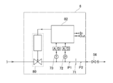
- FIG. 3 is a view schematically showing a configuration example of the fluid control unit 6 (pressure type flow control device).
- the orifice member 71 the control valve 80 composed of the metal diaphragm valve body and the piezoelectric drive element, the pressure detector 72 provided between the orifice member 71 and the control valve 80, and the temperature And a detector 73.
- the orifice member 71 is provided as a throttling portion, and instead, a critical nozzle or a sonic nozzle may be used.
- the diameter of the orifice or nozzle is set to, for example, 10 ⁇ m to 500 ⁇ m.
- the pressure detector 72 and the temperature detector 73 are connected to the control circuit 82 via an AD converter.
- the AD converter may be incorporated in the control circuit 82.
- the control circuit 82 is also connected to the control valve 80, generates a control signal based on the outputs of the pressure detector 72 and the temperature detector 73, and controls the operation of the control valve 80 by this control signal.
- the pressure type flow control device 6 can perform the same flow control operation as the conventional one, and can control the flow based on the upstream pressure P1 (pressure on the upstream side of the orifice member 71) using the pressure detector 72 .
- the pressure type flow control device 6 may also include a pressure detector on the downstream side of the orifice member 71, and is configured to detect the flow based on the upstream pressure P1 and the downstream pressure P2. It is also good.
- critical expansion conditions P1 / P2 ⁇ about 2 (where P1: gas pressure on the upstream side of the throttling portion (upstream pressure), P2: gas pressure on the downstream side of the throttling portion (downstream pressure),
- P1 gas pressure on the upstream side of the throttling portion (upstream pressure)
- P2 gas pressure on the downstream side of the throttling portion (downstream pressure)
- the flow velocity of the gas passing through the throttle is fixed at the speed of sound, and flow control is performed using the principle that the flow is determined not by the downstream pressure P2 but by the upstream pressure P1.
- the downstream pressure sensor When the downstream pressure sensor is provided, the difference between the upstream pressure P1 and the downstream pressure P2 is small, and the flow rate can be calculated even when the critical expansion condition is not satisfied.
- the flow rate Q can be calculated from the index derived on the basis of
- the control valve 80 is feedback-controlled so that the flow rate approaches the set flow rate input by the user.
- the flow rate obtained by the calculation may be displayed as a flow rate output value.
- the spacer block 50 is connected to the gas heating block 42, and the valve block of the fluid control device 6 is connected to the spacer block 50.
- the gas flow path in the flow path block 5 fixed so as to straddle the gas heating block 42 and the spacer block 50 brings the gas heating chamber 42 a of the gas heating block 42 into communication with the gas flow path of the spacer block 50.
- the gas flow path of the spacer block 50 is in communication with the gas flow path of the valve block of the fluid control device 6.
- downstream side of the stop valve 56 is connected to, for example, the process chamber of the semiconductor manufacturing apparatus, and at the time of gas supply, the inside of the process chamber is depressurized by a vacuum pump and source gas of a predetermined flow rate is supplied to the process chamber .
- a fluid control system can be used, for example, to supply a source gas to a process chamber in a semiconductor manufacturing apparatus for MOCVD.
Landscapes
- Chemical & Material Sciences (AREA)
- Chemical Kinetics & Catalysis (AREA)
- Engineering & Computer Science (AREA)
- Mechanical Engineering (AREA)
- General Chemical & Material Sciences (AREA)
- Materials Engineering (AREA)
- Metallurgy (AREA)
- Organic Chemistry (AREA)
- General Engineering & Computer Science (AREA)
- Chemical Vapour Deposition (AREA)
Abstract
Priority Applications (4)
| Application Number | Priority Date | Filing Date | Title |
|---|---|---|---|
| KR1020197034367A KR102363117B1 (ko) | 2017-07-25 | 2018-07-20 | 유체 제어 장치 |
| CN201880046476.5A CN110914470A (zh) | 2017-07-25 | 2018-07-20 | 流体控制装置 |
| JP2019532558A JP7097085B2 (ja) | 2017-07-25 | 2018-07-20 | 流体制御装置 |
| US16/634,033 US11390951B2 (en) | 2017-07-25 | 2018-07-20 | Fluid control device |
Applications Claiming Priority (2)
| Application Number | Priority Date | Filing Date | Title |
|---|---|---|---|
| JP2017144027 | 2017-07-25 | ||
| JP2017-144027 | 2017-07-25 |
Publications (1)
| Publication Number | Publication Date |
|---|---|
| WO2019021949A1 true WO2019021949A1 (fr) | 2019-01-31 |
Family
ID=65041169
Family Applications (1)
| Application Number | Title | Priority Date | Filing Date |
|---|---|---|---|
| PCT/JP2018/027234 Ceased WO2019021949A1 (fr) | 2017-07-25 | 2018-07-20 | Dispositif de régulation de fluide |
Country Status (6)
| Country | Link |
|---|---|
| US (1) | US11390951B2 (fr) |
| JP (1) | JP7097085B2 (fr) |
| KR (1) | KR102363117B1 (fr) |
| CN (1) | CN110914470A (fr) |
| TW (1) | TWI671426B (fr) |
| WO (1) | WO2019021949A1 (fr) |
Cited By (5)
| Publication number | Priority date | Publication date | Assignee | Title |
|---|---|---|---|---|
| JP2021042474A (ja) * | 2019-09-10 | 2021-03-18 | エーエスエム アイピー ホールディング ビー.ブイ. | 化学物質昇華器のための充填容器およびコネクタ |
| JPWO2021054135A1 (fr) * | 2019-09-19 | 2021-03-25 | ||
| JP2021119307A (ja) * | 2020-01-30 | 2021-08-12 | 株式会社フジキン | 圧電素子駆動式バルブ、圧力式流量制御装置及び気化供給装置 |
| JP2021157701A (ja) * | 2020-03-30 | 2021-10-07 | 株式会社フジキン | 流体制御装置及びこれを用いた流体制御システム |
| JP2023164282A (ja) * | 2022-04-28 | 2023-11-10 | 株式会社Kokusai Electric | ガス供給システム、基板処理装置及び半導体装置の製造方法 |
Families Citing this family (4)
| Publication number | Priority date | Publication date | Assignee | Title |
|---|---|---|---|---|
| JP7216425B2 (ja) * | 2017-11-30 | 2023-02-01 | 株式会社フジキン | 流量制御装置 |
| JP7495742B2 (ja) | 2019-04-25 | 2024-06-05 | 株式会社フジキン | 流量制御装置および流量制御方法 |
| US12424414B2 (en) * | 2021-10-19 | 2025-09-23 | Applied Materials, Inc. | Semiconductor processing system with a manifold for equal splitting and common divert architecture |
| JP2024062056A (ja) * | 2022-10-24 | 2024-05-09 | 愛三工業株式会社 | バルブ装置 |
Citations (6)
| Publication number | Priority date | Publication date | Assignee | Title |
|---|---|---|---|---|
| JPH1187327A (ja) * | 1997-06-25 | 1999-03-30 | Ebara Corp | 液体原料気化装置 |
| JP2000282242A (ja) * | 1999-04-01 | 2000-10-10 | Tokyo Electron Ltd | 気化器、処理装置、処理方法、及び半導体チップの製造方法 |
| JP2001152343A (ja) * | 1999-11-26 | 2001-06-05 | Nec Corp | 気化装置 |
| JP2002217181A (ja) * | 2001-01-19 | 2002-08-02 | Japan Steel Works Ltd:The | 半導体原料供給用気化器 |
| JP2005259723A (ja) * | 2004-02-13 | 2005-09-22 | Utec:Kk | 原料溶液吐出器、cvd用気化器、溶液気化式cvd装置、流量制御方法及び薄膜形成方法 |
| JP2009246173A (ja) * | 2008-03-31 | 2009-10-22 | Tokyo Electron Ltd | 気化器およびそれを用いた成膜装置 |
Family Cites Families (11)
| Publication number | Priority date | Publication date | Assignee | Title |
|---|---|---|---|---|
| US6195504B1 (en) | 1996-11-20 | 2001-02-27 | Ebara Corporation | Liquid feed vaporization system and gas injection device |
| JP3785516B2 (ja) * | 1997-03-07 | 2006-06-14 | 株式会社フジキン | 流体制御装置 |
| JP4487135B2 (ja) * | 2001-03-05 | 2010-06-23 | 東京エレクトロン株式会社 | 流体制御装置 |
| JP4102564B2 (ja) * | 2001-12-28 | 2008-06-18 | 忠弘 大見 | 改良型圧力式流量制御装置 |
| JP4596409B2 (ja) * | 2003-04-21 | 2010-12-08 | 株式会社東京技術研究所 | バルブ装着用ヒータユニット |
| JP2004340199A (ja) * | 2003-05-14 | 2004-12-02 | Fujikin Inc | 加熱装置付き流体制御装置 |
| JP5461786B2 (ja) * | 2008-04-01 | 2014-04-02 | 株式会社フジキン | 気化器を備えたガス供給装置 |
| US9096931B2 (en) * | 2011-10-27 | 2015-08-04 | Asm America, Inc | Deposition valve assembly and method of heating the same |
| JP5837869B2 (ja) | 2012-12-06 | 2015-12-24 | 株式会社フジキン | 原料気化供給装置 |
| CN105716225B (zh) * | 2014-12-22 | 2020-08-11 | 株式会社堀场Stec | 流体加热器、加热块和汽化系统 |
| JP6578125B2 (ja) * | 2015-04-30 | 2019-09-18 | 株式会社フジキン | 気化供給装置 |
-
2018
- 2018-07-20 JP JP2019532558A patent/JP7097085B2/ja active Active
- 2018-07-20 US US16/634,033 patent/US11390951B2/en active Active
- 2018-07-20 CN CN201880046476.5A patent/CN110914470A/zh active Pending
- 2018-07-20 KR KR1020197034367A patent/KR102363117B1/ko active Active
- 2018-07-20 WO PCT/JP2018/027234 patent/WO2019021949A1/fr not_active Ceased
- 2018-07-25 TW TW107125646A patent/TWI671426B/zh active
Patent Citations (6)
| Publication number | Priority date | Publication date | Assignee | Title |
|---|---|---|---|---|
| JPH1187327A (ja) * | 1997-06-25 | 1999-03-30 | Ebara Corp | 液体原料気化装置 |
| JP2000282242A (ja) * | 1999-04-01 | 2000-10-10 | Tokyo Electron Ltd | 気化器、処理装置、処理方法、及び半導体チップの製造方法 |
| JP2001152343A (ja) * | 1999-11-26 | 2001-06-05 | Nec Corp | 気化装置 |
| JP2002217181A (ja) * | 2001-01-19 | 2002-08-02 | Japan Steel Works Ltd:The | 半導体原料供給用気化器 |
| JP2005259723A (ja) * | 2004-02-13 | 2005-09-22 | Utec:Kk | 原料溶液吐出器、cvd用気化器、溶液気化式cvd装置、流量制御方法及び薄膜形成方法 |
| JP2009246173A (ja) * | 2008-03-31 | 2009-10-22 | Tokyo Electron Ltd | 気化器およびそれを用いた成膜装置 |
Cited By (13)
| Publication number | Priority date | Publication date | Assignee | Title |
|---|---|---|---|---|
| JP2021042474A (ja) * | 2019-09-10 | 2021-03-18 | エーエスエム アイピー ホールディング ビー.ブイ. | 化学物質昇華器のための充填容器およびコネクタ |
| JP7767003B2 (ja) | 2019-09-10 | 2025-11-11 | エーエスエム・アイピー・ホールディング・ベー・フェー | 化学物質昇華器のための充填容器およびコネクタ |
| US11976356B2 (en) | 2019-09-19 | 2024-05-07 | Fujikin Incorporated | Vaporized feed device |
| JPWO2021054135A1 (fr) * | 2019-09-19 | 2021-03-25 | ||
| KR20220035485A (ko) | 2019-09-19 | 2022-03-22 | 가부시키가이샤 후지킨 | 기화 공급 장치 |
| CN114269966A (zh) * | 2019-09-19 | 2022-04-01 | 株式会社富士金 | 气化供给装置 |
| JP7577339B2 (ja) | 2019-09-19 | 2024-11-05 | 株式会社フジキン | 気化供給装置 |
| JP2021119307A (ja) * | 2020-01-30 | 2021-08-12 | 株式会社フジキン | 圧電素子駆動式バルブ、圧力式流量制御装置及び気化供給装置 |
| JP7412747B2 (ja) | 2020-01-30 | 2024-01-15 | 株式会社フジキン | 圧電素子駆動式バルブ、圧力式流量制御装置及び気化供給装置 |
| JP2021157701A (ja) * | 2020-03-30 | 2021-10-07 | 株式会社フジキン | 流体制御装置及びこれを用いた流体制御システム |
| JP7470375B2 (ja) | 2020-03-30 | 2024-04-18 | 株式会社フジキン | 流体制御装置及びこれを用いた流体制御システム |
| JP7583505B2 (ja) | 2022-04-28 | 2024-11-14 | 株式会社Kokusai Electric | ガス供給システム、基板処理装置及び半導体装置の製造方法 |
| JP2023164282A (ja) * | 2022-04-28 | 2023-11-10 | 株式会社Kokusai Electric | ガス供給システム、基板処理装置及び半導体装置の製造方法 |
Also Published As
| Publication number | Publication date |
|---|---|
| JP7097085B2 (ja) | 2022-07-07 |
| KR20190140002A (ko) | 2019-12-18 |
| JPWO2019021949A1 (ja) | 2020-06-11 |
| KR102363117B1 (ko) | 2022-02-15 |
| TWI671426B (zh) | 2019-09-11 |
| US20200199753A1 (en) | 2020-06-25 |
| CN110914470A (zh) | 2020-03-24 |
| US11390951B2 (en) | 2022-07-19 |
| TW201908515A (zh) | 2019-03-01 |
Similar Documents
| Publication | Publication Date | Title |
|---|---|---|
| JP7097085B2 (ja) | 流体制御装置 | |
| WO2019021948A1 (fr) | Dispositif de régulation de fluide | |
| JP5461786B2 (ja) | 気化器を備えたガス供給装置 | |
| KR102894024B1 (ko) | 기화 공급 장치 | |
| KR100386217B1 (ko) | 액체재료 기화방법 및 장치 | |
| TWI628717B (zh) | 加熱汽化系統和加熱汽化方法 | |
| CN111095513A (zh) | 高压高温退火腔室 | |
| JP2014114463A5 (fr) | ||
| CN102112656A (zh) | 用于在低压气相中沉积薄层聚合物的方法 | |
| KR100247679B1 (ko) | 액체 소스로 부터 발생된 화학 증기의 통합형 전송장치의 화학증기 전송 모듈 | |
| CN117916864A (zh) | 气化器 | |
| WO2022075111A1 (fr) | Dispositif de vaporisation, dispositif d'alimentation en gaz et procédé de commande pour dispositif d'alimentation en gaz | |
| EP4130333B1 (fr) | Système de vaporisation | |
| JP3808985B2 (ja) | 液体原料の気化装置 | |
| JPH07230322A (ja) | 気化流量制御器 | |
| KR100585891B1 (ko) | 기화기 | |
| JP2024053813A (ja) | 流量制御装置、気化供給装置および流量制御装置の製造方法 | |
| JPH07230321A (ja) | 液体材料気化供給装置 | |
| KR20150048447A (ko) | 기화기 및 원료 공급 장치 |
Legal Events
| Date | Code | Title | Description |
|---|---|---|---|
| 121 | Ep: the epo has been informed by wipo that ep was designated in this application |
Ref document number: 18837236 Country of ref document: EP Kind code of ref document: A1 |
|
| ENP | Entry into the national phase |
Ref document number: 2019532558 Country of ref document: JP Kind code of ref document: A |
|
| ENP | Entry into the national phase |
Ref document number: 20197034367 Country of ref document: KR Kind code of ref document: A |
|
| NENP | Non-entry into the national phase |
Ref country code: DE |
|
| 122 | Ep: pct application non-entry in european phase |
Ref document number: 18837236 Country of ref document: EP Kind code of ref document: A1 |