WO2022075111A1 - Dispositif de vaporisation, dispositif d'alimentation en gaz et procédé de commande pour dispositif d'alimentation en gaz - Google Patents
Dispositif de vaporisation, dispositif d'alimentation en gaz et procédé de commande pour dispositif d'alimentation en gaz Download PDFInfo
- Publication number
- WO2022075111A1 WO2022075111A1 PCT/JP2021/035455 JP2021035455W WO2022075111A1 WO 2022075111 A1 WO2022075111 A1 WO 2022075111A1 JP 2021035455 W JP2021035455 W JP 2021035455W WO 2022075111 A1 WO2022075111 A1 WO 2022075111A1
- Authority
- WO
- WIPO (PCT)
- Prior art keywords
- raw material
- liquid
- vaporizer
- gas
- liquid raw
- Prior art date
- Legal status (The legal status is an assumption and is not a legal conclusion. Google has not performed a legal analysis and makes no representation as to the accuracy of the status listed.)
- Ceased
Links
Images







Classifications
-
- C—CHEMISTRY; METALLURGY
- C23—COATING METALLIC MATERIAL; COATING MATERIAL WITH METALLIC MATERIAL; CHEMICAL SURFACE TREATMENT; DIFFUSION TREATMENT OF METALLIC MATERIAL; COATING BY VACUUM EVAPORATION, BY SPUTTERING, BY ION IMPLANTATION OR BY CHEMICAL VAPOUR DEPOSITION, IN GENERAL; INHIBITING CORROSION OF METALLIC MATERIAL OR INCRUSTATION IN GENERAL
- C23C—COATING METALLIC MATERIAL; COATING MATERIAL WITH METALLIC MATERIAL; SURFACE TREATMENT OF METALLIC MATERIAL BY DIFFUSION INTO THE SURFACE, BY CHEMICAL CONVERSION OR SUBSTITUTION; COATING BY VACUUM EVAPORATION, BY SPUTTERING, BY ION IMPLANTATION OR BY CHEMICAL VAPOUR DEPOSITION, IN GENERAL
- C23C16/00—Chemical coating by decomposition of gaseous compounds, without leaving reaction products of surface material in the coating, i.e. chemical vapour deposition [CVD] processes
- C23C16/44—Chemical coating by decomposition of gaseous compounds, without leaving reaction products of surface material in the coating, i.e. chemical vapour deposition [CVD] processes characterised by the method of coating
- C23C16/448—Chemical coating by decomposition of gaseous compounds, without leaving reaction products of surface material in the coating, i.e. chemical vapour deposition [CVD] processes characterised by the method of coating characterised by the method used for generating reactive gas streams, e.g. by evaporation or sublimation of precursor materials
- C23C16/4485—Chemical coating by decomposition of gaseous compounds, without leaving reaction products of surface material in the coating, i.e. chemical vapour deposition [CVD] processes characterised by the method of coating characterised by the method used for generating reactive gas streams, e.g. by evaporation or sublimation of precursor materials by evaporation without using carrier gas in contact with the source material
-
- B—PERFORMING OPERATIONS; TRANSPORTING
- B01—PHYSICAL OR CHEMICAL PROCESSES OR APPARATUS IN GENERAL
- B01B—BOILING; BOILING APPARATUS ; EVAPORATION; EVAPORATION APPARATUS
- B01B1/00—Boiling; Boiling apparatus for physical or chemical purposes ; Evaporation in general
- B01B1/005—Evaporation for physical or chemical purposes; Evaporation apparatus therefor, e.g. evaporation of liquids for gas phase reactions
-
- B—PERFORMING OPERATIONS; TRANSPORTING
- B01—PHYSICAL OR CHEMICAL PROCESSES OR APPARATUS IN GENERAL
- B01J—CHEMICAL OR PHYSICAL PROCESSES, e.g. CATALYSIS OR COLLOID CHEMISTRY; THEIR RELEVANT APPARATUS
- B01J4/00—Feed or outlet devices; Feed or outlet control devices
-
- B—PERFORMING OPERATIONS; TRANSPORTING
- B01—PHYSICAL OR CHEMICAL PROCESSES OR APPARATUS IN GENERAL
- B01J—CHEMICAL OR PHYSICAL PROCESSES, e.g. CATALYSIS OR COLLOID CHEMISTRY; THEIR RELEVANT APPARATUS
- B01J4/00—Feed or outlet devices; Feed or outlet control devices
- B01J4/001—Feed or outlet devices as such, e.g. feeding tubes
-
- B—PERFORMING OPERATIONS; TRANSPORTING
- B01—PHYSICAL OR CHEMICAL PROCESSES OR APPARATUS IN GENERAL
- B01J—CHEMICAL OR PHYSICAL PROCESSES, e.g. CATALYSIS OR COLLOID CHEMISTRY; THEIR RELEVANT APPARATUS
- B01J4/00—Feed or outlet devices; Feed or outlet control devices
- B01J4/008—Feed or outlet control devices
-
- B—PERFORMING OPERATIONS; TRANSPORTING
- B01—PHYSICAL OR CHEMICAL PROCESSES OR APPARATUS IN GENERAL
- B01J—CHEMICAL OR PHYSICAL PROCESSES, e.g. CATALYSIS OR COLLOID CHEMISTRY; THEIR RELEVANT APPARATUS
- B01J7/00—Apparatus for generating gases
-
- C—CHEMISTRY; METALLURGY
- C23—COATING METALLIC MATERIAL; COATING MATERIAL WITH METALLIC MATERIAL; CHEMICAL SURFACE TREATMENT; DIFFUSION TREATMENT OF METALLIC MATERIAL; COATING BY VACUUM EVAPORATION, BY SPUTTERING, BY ION IMPLANTATION OR BY CHEMICAL VAPOUR DEPOSITION, IN GENERAL; INHIBITING CORROSION OF METALLIC MATERIAL OR INCRUSTATION IN GENERAL
- C23C—COATING METALLIC MATERIAL; COATING MATERIAL WITH METALLIC MATERIAL; SURFACE TREATMENT OF METALLIC MATERIAL BY DIFFUSION INTO THE SURFACE, BY CHEMICAL CONVERSION OR SUBSTITUTION; COATING BY VACUUM EVAPORATION, BY SPUTTERING, BY ION IMPLANTATION OR BY CHEMICAL VAPOUR DEPOSITION, IN GENERAL
- C23C16/00—Chemical coating by decomposition of gaseous compounds, without leaving reaction products of surface material in the coating, i.e. chemical vapour deposition [CVD] processes
- C23C16/44—Chemical coating by decomposition of gaseous compounds, without leaving reaction products of surface material in the coating, i.e. chemical vapour deposition [CVD] processes characterised by the method of coating
- C23C16/448—Chemical coating by decomposition of gaseous compounds, without leaving reaction products of surface material in the coating, i.e. chemical vapour deposition [CVD] processes characterised by the method of coating characterised by the method used for generating reactive gas streams, e.g. by evaporation or sublimation of precursor materials
-
- C—CHEMISTRY; METALLURGY
- C23—COATING METALLIC MATERIAL; COATING MATERIAL WITH METALLIC MATERIAL; CHEMICAL SURFACE TREATMENT; DIFFUSION TREATMENT OF METALLIC MATERIAL; COATING BY VACUUM EVAPORATION, BY SPUTTERING, BY ION IMPLANTATION OR BY CHEMICAL VAPOUR DEPOSITION, IN GENERAL; INHIBITING CORROSION OF METALLIC MATERIAL OR INCRUSTATION IN GENERAL
- C23C—COATING METALLIC MATERIAL; COATING MATERIAL WITH METALLIC MATERIAL; SURFACE TREATMENT OF METALLIC MATERIAL BY DIFFUSION INTO THE SURFACE, BY CHEMICAL CONVERSION OR SUBSTITUTION; COATING BY VACUUM EVAPORATION, BY SPUTTERING, BY ION IMPLANTATION OR BY CHEMICAL VAPOUR DEPOSITION, IN GENERAL
- C23C16/00—Chemical coating by decomposition of gaseous compounds, without leaving reaction products of surface material in the coating, i.e. chemical vapour deposition [CVD] processes
- C23C16/44—Chemical coating by decomposition of gaseous compounds, without leaving reaction products of surface material in the coating, i.e. chemical vapour deposition [CVD] processes characterised by the method of coating
- C23C16/455—Chemical coating by decomposition of gaseous compounds, without leaving reaction products of surface material in the coating, i.e. chemical vapour deposition [CVD] processes characterised by the method of coating characterised by the method used for introducing gases into reaction chamber or for modifying gas flows in reaction chamber
- C23C16/45561—Gas plumbing upstream of the reaction chamber
-
- C—CHEMISTRY; METALLURGY
- C23—COATING METALLIC MATERIAL; COATING MATERIAL WITH METALLIC MATERIAL; CHEMICAL SURFACE TREATMENT; DIFFUSION TREATMENT OF METALLIC MATERIAL; COATING BY VACUUM EVAPORATION, BY SPUTTERING, BY ION IMPLANTATION OR BY CHEMICAL VAPOUR DEPOSITION, IN GENERAL; INHIBITING CORROSION OF METALLIC MATERIAL OR INCRUSTATION IN GENERAL
- C23C—COATING METALLIC MATERIAL; COATING MATERIAL WITH METALLIC MATERIAL; SURFACE TREATMENT OF METALLIC MATERIAL BY DIFFUSION INTO THE SURFACE, BY CHEMICAL CONVERSION OR SUBSTITUTION; COATING BY VACUUM EVAPORATION, BY SPUTTERING, BY ION IMPLANTATION OR BY CHEMICAL VAPOUR DEPOSITION, IN GENERAL
- C23C16/00—Chemical coating by decomposition of gaseous compounds, without leaving reaction products of surface material in the coating, i.e. chemical vapour deposition [CVD] processes
- C23C16/44—Chemical coating by decomposition of gaseous compounds, without leaving reaction products of surface material in the coating, i.e. chemical vapour deposition [CVD] processes characterised by the method of coating
- C23C16/52—Controlling or regulating the coating process
-
- F—MECHANICAL ENGINEERING; LIGHTING; HEATING; WEAPONS; BLASTING
- F17—STORING OR DISTRIBUTING GASES OR LIQUIDS
- F17C—VESSELS FOR CONTAINING OR STORING COMPRESSED, LIQUEFIED OR SOLIDIFIED GASES; FIXED-CAPACITY GAS-HOLDERS; FILLING VESSELS WITH, OR DISCHARGING FROM VESSELS, COMPRESSED, LIQUEFIED, OR SOLIDIFIED GASES
- F17C7/00—Methods or apparatus for discharging liquefied, solidified, or compressed gases from pressure vessels, not covered by another subclass
- F17C7/02—Discharging liquefied gases
- F17C7/04—Discharging liquefied gases with change of state, e.g. vaporisation
-
- H—ELECTRICITY
- H10—SEMICONDUCTOR DEVICES; ELECTRIC SOLID-STATE DEVICES NOT OTHERWISE PROVIDED FOR
- H10P—GENERIC PROCESSES OR APPARATUS FOR THE MANUFACTURE OR TREATMENT OF DEVICES COVERED BY CLASS H10
- H10P14/00—Formation of materials, e.g. in the shape of layers or pillars
- H10P14/60—Formation of materials, e.g. in the shape of layers or pillars of insulating materials
-
- B—PERFORMING OPERATIONS; TRANSPORTING
- B01—PHYSICAL OR CHEMICAL PROCESSES OR APPARATUS IN GENERAL
- B01J—CHEMICAL OR PHYSICAL PROCESSES, e.g. CATALYSIS OR COLLOID CHEMISTRY; THEIR RELEVANT APPARATUS
- B01J2204/00—Aspects relating to feed or outlet devices; Regulating devices for feed or outlet devices
- B01J2204/002—Aspects relating to feed or outlet devices; Regulating devices for feed or outlet devices the feeding side being of particular interest
-
- B—PERFORMING OPERATIONS; TRANSPORTING
- B01—PHYSICAL OR CHEMICAL PROCESSES OR APPARATUS IN GENERAL
- B01J—CHEMICAL OR PHYSICAL PROCESSES, e.g. CATALYSIS OR COLLOID CHEMISTRY; THEIR RELEVANT APPARATUS
- B01J2204/00—Aspects relating to feed or outlet devices; Regulating devices for feed or outlet devices
- B01J2204/007—Aspects relating to the heat-exchange of the feed or outlet devices
Definitions
- This disclosure relates to a vaporizer, a gas supply device, and a control method for the gas supply device.
- a substrate processing system that vaporizes a liquid raw material and supplies a raw material gas to a film forming processing apparatus is known.
- Patent Document 1 describes a vaporizer for vaporizing a liquid material, a supply amount control device for controlling the supply amount of the liquid material to the vaporizer, a flow path formed inside, and the vaporizer and the supply. It is provided with a manifold block having an equipment mounting surface to which the amount control equipment is attached, and the vaporizer and the supply amount control equipment are configured to be connected via the flow path by being attached to the equipment mounting surface.
- the vaporized system is disclosed.
- the present disclosure provides a method for controlling a vaporizer, a gas supply device, and a gas supply device in which the device is small and can supply a large flow rate of gas.
- the heat exchange unit includes a heat exchange unit that heats the liquid raw material and a vaporization unit that vaporizes the heated liquid raw material into a raw material gas.
- a vaporizer having a branch portion to which the liquid raw material is supplied and branched, and a thin tube portion connected to the branch portion, respectively.
- a vaporization device a gas supply device, and a control method for a gas supply device, in which the device is small and can supply a large flow rate of gas.
- FIG. 1 is an example of a configuration diagram of a substrate processing system 1 including a vaporizer 20 according to the first embodiment.
- the substrate processing system 1 includes a liquid raw material supply source 2, a liquid material vaporization supply device 3, and a processing container 4.
- the substrate processing system 1 supplies the liquid raw material (liquid precursor) supplied from the liquid raw material supply source 2 to the liquid material vaporization supply device 3.
- the substrate processing system 1 is a substrate W mounted on a mounting table 5 in the processing container 4 by supplying the vaporized raw material gas to the processing container 4 by vaporizing the liquid raw material in the liquid material vaporization supply device 3. Is subjected to a desired treatment (for example, a film forming treatment).
- the liquid raw material supply source 2 and the liquid material vaporization supply device 3 function as a gas supply device for supplying the raw material gas to the processing container 4.
- the liquid raw material supply source 2 stores the liquid raw material and supplies the liquid raw material to the liquid material vaporization supply device 3.
- the liquid material vaporization supply device 3 vaporizes the liquid raw material supplied from the liquid raw material supply source 2 and stores the vaporized raw material gas. Further, the liquid material vaporization supply device 3 supplies the stored raw material gas to the processing container 4.
- the liquid material vaporization supply device 3 includes a liquid supply valve 10, a vaporization device 20, a gas flow rate adjusting device 30, and a control device 40.
- the liquid supply valve 10 is, for example, an on-off valve, and is provided in a supply path for supplying the liquid raw material from the liquid raw material supply source 2 to the liquid material vaporization supply device 3.
- the opening and closing of the liquid supply valve 10 is controlled by the control device 40.
- the vaporizer 20 includes a heat exchange unit 21, a vaporizer 24, a fill tank 25, and a heater 26.
- the heat exchange section 21 includes a branch section 22 and a plurality of thin tube sections 23.
- the flow path of the liquid raw material supplied from the liquid raw material supply source 2 branches to the plurality of thin tube portions 23 at the branch portion 22.
- the thin tube portion 23 is formed with a fine and long flow path. Further, the heat exchange unit 21 is heated by the heater 26.
- the liquid raw material flowing through the thin tube portion 23 is heated to a predetermined heating temperature by exchanging heat with the thin tube portion 23 heated by the heater 26. With such a configuration, the liquid raw material can be efficiently heated in a small space.
- the vaporization unit 24 is connected to each of the plurality of thin tube units 23.
- a flow path is formed so that the space (flow path) expands from the upstream side to the downstream side.
- the vaporization unit 24 is formed so that the cross-sectional area of the flow path expands from the upstream side to the downstream side, for example.
- the inner diameter of the flow path is formed to increase from the upstream side to the downstream side.
- the flow path is formed so as to taper from the upstream side to the downstream side.
- the vaporization unit 24 is heated by the heater 26.
- the liquid raw material heated to the heating temperature in the thin tube portion 23 is supplied to the vaporization portion 24. Since the vaporization unit 24 is formed so that the space (flow path) expands from the upstream side to the downstream side, the pressure in the flow path of the vaporization unit 24 is lowered to the vapor pressure or lower of the heating temperature. As a result, the liquid raw material is forcibly boiled by convection in the flow path of the vaporization unit 24, and the liquid raw material is vaporized to become a raw material gas.
- the flow paths of the thin tube portion 23 and the vaporization portion 24 have a structure in which the pressure loss is small and the liquid raw material can be further depressurized. Therefore, the heating temperature required for vaporizing the liquid raw material is set. Can be reduced. As a result, deterioration due to heat of the raw material can be suppressed.
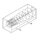
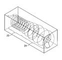
- FIG. 2A and 2B are examples of perspective views showing a thin tube portion 23 and a vaporization portion 24 in the vaporization device 20 according to the first embodiment.
- FIG. 2A is a perspective view seen from the side of the thin tube portion 23, and
- FIG. 2B is a perspective view seen from the side of the vaporization portion 24.
- the flow paths of the thin tube portion 23 and the vaporization portion 24 are formed in a spiral shape (helical curve). Further, the cross-sectional area of the flow path of the thin tube portion 23 is constant. On the other hand, the cross-sectional area of the flow path of the vaporization unit 24 is formed so as to expand on the downstream side rather than on the upstream side.
- a spiral-shaped flow path is formed.
- the spiral flow path of the thin tube portion 23 and / or the vaporization portion 24 may be integrally or separately formed by additive manufacturing (3D printer) such as powder sintering, and holes (holes) may be formed.
- additive manufacturing 3D printer
- holes holes
- / or a plate-shaped member laminated structure in which a plurality of plate-shaped members provided with grooves (groove portions) are laminated and joined may be used. With such a structure, the thin tube portion 23 and the vaporization portion 24 having a complicated flow path inside can be easily formed.
- the fill tank 25 is filled with the raw material gas vaporized by the vaporization unit 24. Further, the fill tank 25 is heated by the heater 26.
- the piping from the outlet of the fill tank 25 to the gas flow rate adjusting device 30 or the piping from the outlet of the fill tank 25 to the processing container 4 is higher than the temperature of the fill tank 25 for the purpose of preventing the reliquefaction of the raw material gas. It may be heated so as to.
- the gas flow rate adjusting device 30 includes a pressure sensor 31, a flow rate sensor 32, and a flow rate control valve 33.
- the pressure sensor 31 detects the pressure of the raw material gas. Although the pressure sensor 31 is shown in FIG. 1 as being provided in the supply path for supplying the raw material gas from the vaporizer 20 to the processing container 4. The present invention is not limited to this, and may be provided in, for example, the fill tank 25. The pressure of the raw material gas detected by the pressure sensor 31 is output to the control device 40.
- the flow rate sensor 32 detects the flow rate of the raw material gas. As shown in FIG. 1, the flow rate sensor 32 is provided in the supply path for supplying the raw material gas from the vaporizer 20 to the processing container 4. The flow rate of the raw material gas detected by the flow rate sensor 32 is output to the control device 40.
- the flow rate control valve 33 is provided in the supply path for supplying the raw material gas from the vaporizer 20 to the processing container 4, and controls the flow rate of the raw material gas supplied from the vaporizer 20 to the processing container 4.
- the opening degree (flow rate) of the flow rate control valve 33 is controlled by the control device 40.
- the control device 40 controls the opening and closing of the liquid supply valve 10 based on the pressure of the raw material gas detected by the pressure sensor 31. Further, the control device 40 controls the opening and closing of the flow rate control valve 33 based on the flow rate of the raw material gas detected by the flow rate sensor 32.
- FIG. 3 is an example of a graph illustrating the flow rate of the raw material gas, the pressure of the raw material gas, and the control of the liquid supply valve 10.
- FIG. 3A is a graph illustrating the time change of the flow rate of the raw material gas.
- FIG. 3B is a graph illustrating the time change of the pressure of the raw material gas.
- FIG. 3C is a graph illustrating the time change of opening and closing of the liquid supply valve 10.
- the control device 40 controls the opening and closing of the flow rate control valve 33 based on the flow rate of the raw material gas detected by the flow rate sensor 32. As a result, even if the pressure of the raw material gas in the fill tank 25 fluctuates, the raw material gas can be supplied to the processing container 4 at a constant flow rate.
- the control device 40 controls the opening and closing of the liquid supply valve 10 based on the pressure of the raw material gas detected by the pressure sensor 31.
- the control device 40 opens the liquid supply valve 10 when the pressure of the raw material gas detected by the pressure sensor 31 reaches a predetermined threshold value (indicated by a broken line). Then, when the predetermined time elapses, the control device 40 closes the liquid supply valve 10.
- the predetermined time for opening the liquid supply valve 10 may be set based on the amount of liquid so that all the liquid raw materials supplied by the vaporization unit 24 can be vaporized.
- the liquid supply valve 10 is arranged between the branch portion 22 and the liquid raw material supply source 2, but even if the liquid supply valve is arranged in each line branched at the branch portion. good.
- FIGS. 4A to 4C are examples of cross-sectional views illustrating the pipe shape of the vaporization unit 24.
- FIG. 4A is an example of a diagram illustrating the state of the raw material in the circular pipe-shaped pipe 111.
- the raw material flowing through the vaporization unit 24 (pipe 111) is in a gas-liquid mixed state (slag flow, circular flow) of the liquid raw material 200 and the raw material gas 201.
- the liquid raw material 200 is located so as to cover the inner wall surface of the pipe 111. Therefore, the raw material gas 201 and the wall surface of the pipe 111 are not in direct contact with each other.
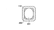
- FIG. 4B is an example of a diagram illustrating the state of the raw material in the square tube-shaped pipe 112.
- the raw material flowing through the vaporization unit 24 (pipe 112) is in a gas-liquid mixed state (slag flow, circular flow) of the liquid raw material 200 and the raw material gas 201.
- the liquid raw material 200 is located at the corner of the inner wall surface of the pipe 112. Therefore, in the vicinity of the center of the square-shaped side, the raw material gas 201 and the wall surface of the pipe 112 are in direct contact with each other.
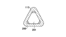
- FIG. 4C is an example of a diagram illustrating the state of the raw material in the triangular pipe-shaped pipe 113.
- the raw material flowing through the vaporization unit 24 (pipe 113) is in a gas-liquid mixed state (slag flow, circular flow) of the liquid raw material 200 and the raw material gas 201.
- the liquid raw material 200 is located at the corner of the inner wall surface of the pipe 113. Therefore, in the vicinity of the center of the triangular side, the raw material gas 201 and the wall surface of the pipe 113 are in direct contact with each other.
- the cross-sectional shape of the pipe in the vaporization unit 24 may be polygonal.
- the heat exchange efficiency between the heated pipe wall surface and the gas raw material is higher than the heat exchange efficiency between the heated pipe wall surface and the liquid raw material. Therefore, as shown in FIGS. 4B and 4C, by providing a corner portion in the cross-sectional shape of the pipe, the contact area between the heated pipe wall surface and the gas raw material can be widened, and the heat exchangeability is improved. be able to.
- the substrate processing system according to the second embodiment has a different configuration of the vaporizer 20A as compared with the substrate processing system 1 (see FIG. 1) according to the first embodiment.
- Other configurations are the same, and duplicate explanations will be omitted.
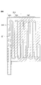
- FIG. 5 is an example of a perspective view showing the vaporizer 20A according to the second embodiment.
- FIG. 6 is an example of a cross-sectional view showing a branch portion 22A of the vaporizer 20A according to the second embodiment.
- FIG. 7 is an example of a cross-sectional view showing a thin tube portion 23A and a vaporization portion 24A of the vaporizer 20A according to the second embodiment.
- the fill tank 25 and the heater 26 are not shown.
- the vaporizer 20A includes a heat exchange unit 21A, a vaporization unit 24A, a fill tank (not shown), and a heater (not shown).
- the heat exchange section 21A includes a branch section 22A and a plurality of thin tube sections 23A. As shown in FIG. 6, the flow path formed in the branch portion 22A has a large diameter portion 221 and a small diameter portion 222 branched from the large diameter portion 221. As shown in FIG. 7, the small diameter portion 222 is connected to the thin tube portion 23A. Further, the thin tube portion 23A is connected to the vaporization portion 24A.
- the liquid raw material supplied from the liquid raw material supply source 2 branches to a plurality of thin tube portions 23A at the branch portion 22A. Further, the heat exchange unit 21A is heated by a heater. The liquid raw material flowing through the thin tube portion 23A is heated to a predetermined heating temperature by exchanging heat with the thin tube portion 23A heated by the heater. With such a configuration, the liquid raw material can be efficiently heated in a small space.
- the vaporization section 24A is connected to each of the plurality of thin tube sections 23A.
- the vaporization unit 24A is formed so that the space (flow path) expands from the upstream side to the downstream side.
- the vaporization unit 24A is formed so that the cross-sectional area of the flow path expands from the upstream side to the downstream side, for example.
- the inner diameter of the flow path is formed to increase from the upstream side to the downstream side.
- the flow path is formed so as to taper from the upstream side to the downstream side.
- the vaporization unit 24 is heated by the heater 26.
- the liquid raw material heated to the heating temperature in the thin tube portion 23A is supplied to the vaporization portion 24A.
- the vaporization unit 24A is formed so that the space (flow path) expands from the upstream side to the downstream side, so that the pressure in the flow path of the vaporization unit 24A is lowered to the vapor pressure or lower of the heating temperature.
- the liquid raw material is forcibly boiled by convection in the flow path of the vaporization unit 24A, and the liquid raw material is vaporized to become a raw material gas.
- a U-shaped flow path is formed.
- the U-shaped flow path of the thin tube portion 23 and the vaporization portion 24 may be formed by, for example, connecting plates having recesses.
- the substrate processing system according to the third embodiment has a different configuration of the vaporizer 20B as compared with the substrate processing system 1 (see FIG. 1) according to the first embodiment.
- Other configurations are the same, and duplicate explanations will be omitted.
- FIG. 8 is an example of a cross-sectional view showing the vaporizer 20B according to the third embodiment.
- FIG. 9 is an example of a perspective view showing the heat exchange unit 21B of the vaporizer 20B according to the third embodiment.
- the heater is not shown.
- the vaporizer 20B includes a heat exchange unit 21B, a vaporization chamber 27B, and a heater (not shown).
- the vaporization chamber 27B has a multi-stage tray 28B. Further, a sensor 29B is provided at the bottom of the vaporization chamber 27B.
- the heat exchange section 21B includes a branch section 22B and a plurality of thin tube sections 23B.
- the thin tube portion 23B forms a spiral-shaped flow path. As a result, it is possible to form a long flow path with little pressure loss in a space having a small occupied area.
- the heat exchange unit 21B is heated by a heater.
- the liquid raw material supplied to the heat exchange unit 21B is heated to a predetermined heating temperature.
- the heated liquid raw material is supplied to the vaporization chamber 27B.
- the flow path of the thin tube portion 23B of the heat exchange section 21B has been described as an example of a spiral flow path, the flow path is not limited to this, and may be a U-shaped flow path.
- the vaporization chamber 27B has a larger space than the thin tube portion 23B. As a result, the liquid raw material supplied to the vaporization chamber 27B is depressurized and boils (vaporizes). Further, the liquid raw material supplied to the vaporization chamber 27B spreads on the tray 28B. The vaporization chamber 27B and the tray 28B are heated by a heater. As a result, the liquid raw material on the tray 28 is also vaporized. The vaporized raw material gas is filled in the vaporization chamber 27B. That is, the vaporization chamber 27B also has a function as a fill tank.
- the trays 28B are arranged alternately as shown in FIG.
- the liquid raw material that has flowed into the vaporization chamber 27B flows into the tray 28B of one stage, and flows into the tray 28B of the next stage from the end of the tray 28B of one stage, so that the liquid raw material is supplied in order from the upper stage. It has become like.
- the sensor 29B provided at the bottom of the vaporization chamber 27B is a sensor that detects liquid.
- the control device 40 controls to close the liquid supply valve 10 (see FIG. 1). As a result, it is possible to prevent the liquid raw material from being excessively supplied to the tray 28B of the vaporization chamber 27B, and to efficiently vaporize the liquid raw material.
- the present disclosure is not limited to the above embodiments and the like, and is described in the scope of claims. Various modifications and improvements are possible within the scope of the gist of the disclosure.
- Substrate processing system 2 Liquid raw material supply source 3 Liquid material vaporization supply device 4 Processing container 5 Mounting stand 10 Liquid supply valve 20 Vaporizer 21 Heat exchange section 22 Branch section 23 Thin tube section 24 Vaporization section 25 Fill tank 26 Heater 30 Gas flow rate adjustment Device 31 Pressure sensor 32 Flow sensor 33 Flow control valve 40 Control device 111-113 Piping 200 Liquid raw material 201 Raw material gas
Landscapes
- Chemical & Material Sciences (AREA)
- Chemical Kinetics & Catalysis (AREA)
- Organic Chemistry (AREA)
- Engineering & Computer Science (AREA)
- Mechanical Engineering (AREA)
- General Chemical & Material Sciences (AREA)
- Materials Engineering (AREA)
- Metallurgy (AREA)
- General Engineering & Computer Science (AREA)
- Chemical Vapour Deposition (AREA)
- Filling Or Discharging Of Gas Storage Vessels (AREA)
- Feeding, Discharge, Calcimining, Fusing, And Gas-Generation Devices (AREA)
Abstract
Priority Applications (2)
| Application Number | Priority Date | Filing Date | Title |
|---|---|---|---|
| US18/247,489 US20240003006A1 (en) | 2020-10-07 | 2021-09-27 | Vaporizer, gas supply apparatus, and method of controlling gas supply apparatus |
| KR1020237015046A KR102937537B1 (ko) | 2020-10-07 | 2021-09-27 | 기화 장치, 가스 공급 장치 및 가스 공급 장치 제어 방법 |
Applications Claiming Priority (2)
| Application Number | Priority Date | Filing Date | Title |
|---|---|---|---|
| JP2020-169970 | 2020-10-07 | ||
| JP2020169970A JP7589890B2 (ja) | 2020-10-07 | 2020-10-07 | 気化装置、ガス供給装置及びガス供給装置の制御方法 |
Publications (1)
| Publication Number | Publication Date |
|---|---|
| WO2022075111A1 true WO2022075111A1 (fr) | 2022-04-14 |
Family
ID=81125917
Family Applications (1)
| Application Number | Title | Priority Date | Filing Date |
|---|---|---|---|
| PCT/JP2021/035455 Ceased WO2022075111A1 (fr) | 2020-10-07 | 2021-09-27 | Dispositif de vaporisation, dispositif d'alimentation en gaz et procédé de commande pour dispositif d'alimentation en gaz |
Country Status (5)
| Country | Link |
|---|---|
| US (1) | US20240003006A1 (fr) |
| JP (1) | JP7589890B2 (fr) |
| KR (1) | KR102937537B1 (fr) |
| TW (1) | TWI896767B (fr) |
| WO (1) | WO2022075111A1 (fr) |
Families Citing this family (2)
| Publication number | Priority date | Publication date | Assignee | Title |
|---|---|---|---|---|
| JP2025019830A (ja) * | 2023-07-28 | 2025-02-07 | 東京エレクトロン株式会社 | 気化装置、水蒸気処理システムおよび水蒸気処理方法 |
| KR102893884B1 (ko) * | 2025-04-28 | 2025-12-03 | (주)액트로 | 식각 장치 |
Citations (6)
| Publication number | Priority date | Publication date | Assignee | Title |
|---|---|---|---|---|
| JPH02112327U (fr) * | 1989-02-20 | 1990-09-07 | ||
| JP2006202965A (ja) * | 2005-01-20 | 2006-08-03 | Lintec Co Ltd | 気化装置とその気化構造 |
| JP2007046084A (ja) * | 2005-08-08 | 2007-02-22 | Lintec Co Ltd | 気化器並びにこれを用いた液体気化供給装置 |
| JP2007518267A (ja) * | 2004-01-05 | 2007-07-05 | エムエスピー・コーポレーション | 液状前駆物質のための高性能蒸発器、及び、半導体の薄膜蒸着における複数の液状前駆物質の蒸発 |
| WO2013146680A1 (fr) * | 2012-03-30 | 2013-10-03 | 株式会社ブイテックス | Dispositif de vaporisation |
| WO2016174832A1 (fr) * | 2015-04-30 | 2016-11-03 | 株式会社フジキン | Appareil d'alimentation à vaporisation |
Family Cites Families (2)
| Publication number | Priority date | Publication date | Assignee | Title |
|---|---|---|---|---|
| JP2012204791A (ja) * | 2011-03-28 | 2012-10-22 | Tokyo Electron Ltd | 気化装置、ガス供給装置及びこれを用いた成膜装置 |
| CN105714271B (zh) | 2014-12-22 | 2020-07-31 | 株式会社堀场Stec | 汽化系统 |
-
2020
- 2020-10-07 JP JP2020169970A patent/JP7589890B2/ja active Active
-
2021
- 2021-09-24 TW TW110135498A patent/TWI896767B/zh active
- 2021-09-27 US US18/247,489 patent/US20240003006A1/en active Pending
- 2021-09-27 KR KR1020237015046A patent/KR102937537B1/ko active Active
- 2021-09-27 WO PCT/JP2021/035455 patent/WO2022075111A1/fr not_active Ceased
Patent Citations (6)
| Publication number | Priority date | Publication date | Assignee | Title |
|---|---|---|---|---|
| JPH02112327U (fr) * | 1989-02-20 | 1990-09-07 | ||
| JP2007518267A (ja) * | 2004-01-05 | 2007-07-05 | エムエスピー・コーポレーション | 液状前駆物質のための高性能蒸発器、及び、半導体の薄膜蒸着における複数の液状前駆物質の蒸発 |
| JP2006202965A (ja) * | 2005-01-20 | 2006-08-03 | Lintec Co Ltd | 気化装置とその気化構造 |
| JP2007046084A (ja) * | 2005-08-08 | 2007-02-22 | Lintec Co Ltd | 気化器並びにこれを用いた液体気化供給装置 |
| WO2013146680A1 (fr) * | 2012-03-30 | 2013-10-03 | 株式会社ブイテックス | Dispositif de vaporisation |
| WO2016174832A1 (fr) * | 2015-04-30 | 2016-11-03 | 株式会社フジキン | Appareil d'alimentation à vaporisation |
Also Published As
| Publication number | Publication date |
|---|---|
| JP2022061803A (ja) | 2022-04-19 |
| US20240003006A1 (en) | 2024-01-04 |
| JP7589890B2 (ja) | 2024-11-26 |
| TWI896767B (zh) | 2025-09-11 |
| KR20230080462A (ko) | 2023-06-07 |
| TW202230470A (zh) | 2022-08-01 |
| KR102937537B1 (ko) | 2026-03-10 |
Similar Documents
| Publication | Publication Date | Title |
|---|---|---|
| US7833353B2 (en) | Liquid material vaporization apparatus for semiconductor processing apparatus | |
| TWI378207B (fr) | ||
| WO2022075111A1 (fr) | Dispositif de vaporisation, dispositif d'alimentation en gaz et procédé de commande pour dispositif d'alimentation en gaz | |
| JP5350824B2 (ja) | 液体材料の気化供給システム | |
| JP2013115208A (ja) | 気化原料供給装置、これを備える基板処理装置、及び気化原料供給方法 | |
| WO2019021949A1 (fr) | Dispositif de régulation de fluide | |
| CN105716225B (zh) | 流体加热器、加热块和汽化系统 | |
| JP2008290044A5 (fr) | ||
| WO2013046517A1 (fr) | Vaporisateur | |
| WO2021054135A1 (fr) | Dispositif d'alimentation vaporisé | |
| KR102071985B1 (ko) | 중간 매체식 가스 기화기 | |
| JP2017198439A (ja) | 蒸気供給装置および蒸気供給方法 | |
| JP2023067758A (ja) | 気化装置、気化装置の制御方法、気化装置用プログラム、及び、流体制御装置 | |
| KR101501311B1 (ko) | 액체 재료 기화 장치 | |
| JP4198941B2 (ja) | プレート型蒸発器 | |
| JP4867722B2 (ja) | 液体濃縮器 | |
| JP6712440B2 (ja) | 液体材料気化装置、液体材料気化システム | |
| JP7577382B2 (ja) | 気化器および気化供給装置 | |
| KR20150055881A (ko) | 원료 공급 장치 | |
| JP6266471B2 (ja) | 流体循環装置および荷電粒子線装置 | |
| JP6136944B2 (ja) | 蒸発器 | |
| CN111074237A (zh) | 源瓶 | |
| JP2007046084A (ja) | 気化器並びにこれを用いた液体気化供給装置 | |
| JP7316410B1 (ja) | 蒸発冷却システム | |
| JPH0445838A (ja) | 液体材料供給システムにおける気化器 |
Legal Events
| Date | Code | Title | Description |
|---|---|---|---|
| 121 | Ep: the epo has been informed by wipo that ep was designated in this application |
Ref document number: 21877412 Country of ref document: EP Kind code of ref document: A1 |
|
| WWE | Wipo information: entry into national phase |
Ref document number: 18247489 Country of ref document: US |
|
| ENP | Entry into the national phase |
Ref document number: 20237015046 Country of ref document: KR Kind code of ref document: A |
|
| NENP | Non-entry into the national phase |
Ref country code: DE |
|
| 122 | Ep: pct application non-entry in european phase |
Ref document number: 21877412 Country of ref document: EP Kind code of ref document: A1 |