WO2019022021A1 - Dispositif de percussion hydraulique - Google Patents
Dispositif de percussion hydraulique Download PDFInfo
- Publication number
- WO2019022021A1 WO2019022021A1 PCT/JP2018/027543 JP2018027543W WO2019022021A1 WO 2019022021 A1 WO2019022021 A1 WO 2019022021A1 JP 2018027543 W JP2018027543 W JP 2018027543W WO 2019022021 A1 WO2019022021 A1 WO 2019022021A1
- Authority
- WO
- WIPO (PCT)
- Prior art keywords
- stroke
- piston
- valve
- spool
- pressure
- Prior art date
- Legal status (The legal status is an assumption and is not a legal conclusion. Google has not performed a legal analysis and makes no representation as to the accuracy of the status listed.)
- Ceased
Links
Images

Classifications
-
- B—PERFORMING OPERATIONS; TRANSPORTING
- B25—HAND TOOLS; PORTABLE POWER-DRIVEN TOOLS; MANIPULATORS
- B25D—PERCUSSIVE TOOLS
- B25D9/00—Portable percussive tools with fluid-pressure drive, i.e. driven directly by fluids, e.g. having several percussive tool bits operated simultaneously
- B25D9/04—Portable percussive tools with fluid-pressure drive, i.e. driven directly by fluids, e.g. having several percussive tool bits operated simultaneously of the hammer piston type, i.e. in which the tool bit or anvil is hit by an impulse member
-
- B—PERFORMING OPERATIONS; TRANSPORTING
- B25—HAND TOOLS; PORTABLE POWER-DRIVEN TOOLS; MANIPULATORS
- B25D—PERCUSSIVE TOOLS
- B25D9/00—Portable percussive tools with fluid-pressure drive, i.e. driven directly by fluids, e.g. having several percussive tool bits operated simultaneously
- B25D9/14—Control devices for the reciprocating piston
- B25D9/16—Valve arrangements therefor
- B25D9/18—Valve arrangements therefor involving a piston-type slide valve
-
- B—PERFORMING OPERATIONS; TRANSPORTING
- B25—HAND TOOLS; PORTABLE POWER-DRIVEN TOOLS; MANIPULATORS
- B25D—PERCUSSIVE TOOLS
- B25D9/00—Portable percussive tools with fluid-pressure drive, i.e. driven directly by fluids, e.g. having several percussive tool bits operated simultaneously
- B25D9/14—Control devices for the reciprocating piston
- B25D9/16—Valve arrangements therefor
- B25D9/20—Valve arrangements therefor involving a tubular-type slide valve
-
- B—PERFORMING OPERATIONS; TRANSPORTING
- B25—HAND TOOLS; PORTABLE POWER-DRIVEN TOOLS; MANIPULATORS
- B25D—PERCUSSIVE TOOLS
- B25D9/00—Portable percussive tools with fluid-pressure drive, i.e. driven directly by fluids, e.g. having several percussive tool bits operated simultaneously
- B25D9/14—Control devices for the reciprocating piston
- B25D9/26—Control devices for adjusting the stroke of the piston or the force or frequency of impact thereof
-
- E—FIXED CONSTRUCTIONS
- E21—EARTH OR ROCK DRILLING; MINING
- E21C—MINING OR QUARRYING
- E21C27/00—Machines which completely free the mineral from the seam
- E21C27/10—Machines which completely free the mineral from the seam by both slitting and breaking-down
- E21C27/12—Machines which completely free the mineral from the seam by both slitting and breaking-down breaking-down effected by acting on the vertical face of the mineral, e.g. by percussive tools
-
- B—PERFORMING OPERATIONS; TRANSPORTING
- B25—HAND TOOLS; PORTABLE POWER-DRIVEN TOOLS; MANIPULATORS
- B25D—PERCUSSIVE TOOLS
- B25D2250/00—General details of portable percussive tools; Components used in portable percussive tools
- B25D2250/131—Idling mode of tools
Definitions
- the present invention relates to a hydraulic striking device such as a rock drill or a breaker, and in particular, a technique for automatically switching the stroke of a piston to a stroke selected from one of a normal stroke and a short stroke shorter than that.
- the present invention relates to an air blow prevention technology that can automatically stop the impact motion of a piston.
- the stroke of the piston is automatically switched to one of the normal stroke and the short stroke according to the hardness of the rock (the amount of penetration into the rock), and the striking force is properly adjusted.
- Various techniques have been proposed for reducing excessive load on the impacting parts such as the rod and the rod pin by adjusting, that is, "auto-stroke mechanism".
- a throttle is provided in an oil passage that operates a valve for stroke control, and the switching timing is adjusted by the throttle.
- the auto-stroke mechanism and the blanking prevention mechanism are individual techniques having different purposes and effects, and can be used properly depending on the desired work content. That is, when the state of the rock to be crushed changes as in the case of underground excavation, it is preferable to use a hydraulic breaker of the auto-stroke specification. On the other hand, when the striking device is repeatedly operated and stopped as in the case of small division work, it is preferable to use a hydraulic breaker of the runaway prevention specification.
- An object of the present invention is to provide a pressure striking device.
- a hydraulic striking device includes a cylinder, a piston slidably fitted to the cylinder so as to be capable of moving forward and backward, and first control for controlling forward and backward movement of the piston A valve, an auto-stroke mechanism for switching the piston stroke of the piston to a normal stroke and a short stroke shorter than the normal stroke, a blanking prevention mechanism for reducing the pressure in the circuit for hydraulically driving the piston to less than the operating pressure And a second control valve for selecting one of the modes of the auto-stroke mechanism and the blanking prevention mechanism, and the second control valve includes a combination of an auto-stroke setting unit and a blanking prevention setting unit.
- the spool is slidably fitted, and the supply of pressure oil to the automatic stroke setting section and the discharge of pressure oil from the overrun prevention setting section are mutually performed.
- a mode selection means for interrupting the operation is provided, and the mode selection means supplies the pressure oil to the auto stroke setting unit, and when the discharge of the pressure oil from the idling prevention setting unit is prohibited, the auto stroke mechanism While being selected, the supply of pressure oil to the auto stroke setting unit is prohibited, and when discharge of the pressure oil from the overrun prevention setting unit is permitted, the overrun prevention mechanism is selected. .
- a hydraulic striking device controls a cylinder, a piston slidably fitted to the cylinder so as to be movable back and forth, and control back and forth movement of the piston First control valve, an auto-stroke mechanism that switches the piston stroke of the piston to a normal stroke and a short stroke shorter than the normal stroke, and an air-pressure reducing circuit in the circuit that drives the And a second control valve for selecting one of the modes of the auto-stroke mechanism and the blanking-preventing mechanism, the second control valve serving as a spool for selecting a mode, for an auto-stroke A spool slidingly fitting portion in which the spool of the second embodiment and the spool for preventing blanking are slidably fitted in a replaceable manner; When the troke spool is slidably fitted, the auto-stroke mechanism is selected, and when the idle-preventing spool is slidably fitted to the spool slidable portion, the idle-preventing mechanism is selected.
- the auto-stroke mechanism and the blanking prevention mechanism can coexist with a simple circuit configuration, and either one can be easily selected.
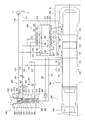
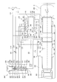
- FIG. 7 is an explanatory view of an operation in a state where the mode selection means is switched to the side of the runaway prevention in the hydraulic striking device of the first embodiment.
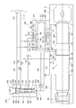
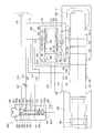
- FIG. 12 is a schematic explanatory view of a second embodiment of a hydraulic striking device according to one aspect of the present invention, and in the same figure, an explanatory view in the case where a spool is reclassified to an auto stroke specification.
- the hydraulic striking device of the second embodiment it is an explanatory view of the operation when the spool is rearranged to the auto stroke specification.
- a hydraulic striking device of a second embodiment of the present invention it is an explanatory view at the time of rearranging a spool to a runaway prevention specification.
- the hydraulic striking device of the second embodiment it is an explanatory view of the operation in the case where the spool is redesigned to the blanking prevention specification.
- the spool slidably fitted to the second control valve has a common specification of auto stroke and blank run prevention, and by providing mode selection means in the hydraulic circuit, the auto stroke mechanism and blank run prevention are provided. This is an example in which the mechanism can be selected.
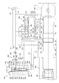
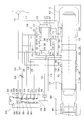
- the hydraulic striking device includes a cylinder 100 and a piston 120, and the first control valve 200 and the second control valve 300 are provided separately from the cylinder 100. .
- the valve 201 is in sliding engagement with the inside of the first control valve 200
- the common spool 320 is in sliding engagement with the inside of the second control valve 300.
- a back head 500 is mounted at the rear of the cylinder 100.
- the back head 500 is filled with a high pressure back head gas G.
- a front head 600 is attached to the front of the cylinder 100.
- a rod 601 is slidably fitted inside the front head 600.
- the piston 120 is a solid cylindrical body, and has a front large diameter portion 121 and a rear large diameter portion 122 as two large diameter portions substantially at the center thereof.
- An intermediate diameter portion 123 is provided in front of the front large diameter portion 121, and a small diameter portion 124 is provided behind the rear large diameter portion 122, and between the front large diameter portion 121 and the rear large diameter portion 122.
- the ring groove 125 is provided.
- a piston front chamber 101 and a piston rear chamber 102 are defined in the front and back of the cylinder 100, respectively.
- a front chamber port 103 is provided in the piston front chamber 101, and the front chamber port 103 is always connected to the high voltage circuit 110 via a front chamber passage 112.
- a rear chamber port 104 is provided in the piston rear chamber 102.
- the rear chamber port 104 and the first control valve 200 are connected by a rear chamber passage 113.
- the piston rear chamber 102 can alternately communicate with the high pressure circuit 110 and the low pressure circuit 111 by switching back and forth by the valve 201 of the first control valve 200.
- An accumulator (not shown) is provided at an appropriate position of the high voltage circuit 110.
- the outer diameter of the medium diameter portion 123 is set larger than the outer diameter of the small diameter portion 124.
- the pressure receiving area of the piston 120 in the piston front chamber 101 and the piston rear chamber 102 that is, the diameter difference between the front large diameter portion 121 and the middle diameter portion 123, and the diameter difference between the rear large diameter portion 122 and the small diameter portion 124
- the piston rear chamber 102 side is larger.
- the hydraulic striking device has an auto-stroke mechanism which moves the piston 120 back and forth in the cylinder 100 to strike the rod 601 by a stroke automatically selected from one of a normal stroke and a short stroke shorter than the normal stroke.
- the pressure oil supplied to the piston front chamber 101 is maintained at or above the start pressure, or the pressure oil supplied to the piston front chamber 101 is greater than the release pressure and less than the start pressure depending on the forward and backward movement position of the piston 120
- a blowout prevention mechanism is selectively provided to control whether the impact stop pressure is a pressure.
- switching between the auto-stroke mechanism and the blanking prevention mechanism is performed by operating the mode selection means 400.
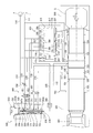
- the stroke control port 105, the spool control port 106, the valve control port 107 and the low pressure port 108 are axially separated from each other between the front chamber port 103 and the rear chamber port 104. It is provided.
- a valve chamber 212 formed non-coaxially with the piston 120 is formed inside, and the valve 201 is slidably fitted in the valve chamber 212.
- the valve chamber 212 includes, in order from front to back, a medium diameter valve front chamber 213, a large diameter valve main chamber 214, and a small diameter valve rear chamber 215.
- a front chamber passage 223 constantly communicating with the high pressure circuit 110 is connected to the valve front chamber 213.
- a front low pressure port 218, a reset port 219, a valve control port 220, and a rear low pressure port 221 are sequentially provided from the front to the rear, and a rear chamber port 222 is provided in the rear valve chamber 215. It is done.
- the front low pressure port 218 is always in communication with the low pressure circuit 111 via the front low pressure passage 224, and the rear low pressure port 221 is always in communication with the low pressure circuit 111 via the rear low pressure passage 227.
- the valve control port 220 and the valve control port 107 communicate with each other via a valve control passage (direct connection) 114.
- the rear chamber port 222 and the rear chamber port 104 communicate with each other via the rear chamber passage 113.
- the valve 201 is a hollow cylindrical body, and has a middle diameter portion 202, a large diameter portion 203, and a small diameter portion 204 in order from the front to the rear.
- the hollow passage 228 inside the cylinder is in constant communication with the high pressure circuit 110 via the front chamber passage 223.
- an oil drainage groove 205 for switching the piston rear chamber 102 to a high pressure and a low pressure is provided in an annular shape on an outer peripheral surface substantially at the center of the small diameter portion 204.
- a communication hole 210 is formed on the front side of the oil drainage groove 205 of the valve 201 so as to penetrate in the radial direction of the valve 201, and a slit groove 211 is axially formed on the outer peripheral surface on the front side of the large diameter portion 203. It is formed in the shape of a slit along it.
- the valve 201 of the present embodiment is always urged rearward by the pressure receiving area difference between the medium diameter portion 202 and the small diameter portion 204, and when high pressure oil is supplied to the valve control port 220, the valve 201 is positioned behind the large diameter portion 203.
- the pressure receiving area of the side stepped surface 209 is added to move forward.
- valve 201 when the valve 201 is in the front end position, that is, when the front end surface 206 abuts on the valve chamber front end surface 216, the rear chamber port 222 is disconnected from the rear low pressure port 221 and the rear end surface 207 The piston rear chamber 102 is connected in high pressure because it communicates with the valve chamber rear end surface 217 and the high pressure connected valve chamber 212 through the hollow passage 228.
- the hydraulic breaker requires the valve control port 220 to maintain high pressure or low pressure, so the valve 201 needs a holding mechanism for maintaining the stopped state at the switching positions of its front end and rear end.
- the holding mechanism when the valve 201 is at the rear end position is the slit groove 211.
- the slit groove 211 causes the valve control port 220 to communicate with the reset port 219 and the front low pressure port 218 so that the rear stepped surface 209 is reliably connected at low pressure and the valve 201 is stopped. It is supposed to maintain the state.
- the holding mechanism when the valve 201 is at the front end position is the communication hole 210.
- the communication hole 210 prevents pressure from being lowered by replenishing the pressure control oil from the hollow passage 228 to the valve control port 220 (and the reset port 219). It is supposed to maintain the stop condition of the
- the hydraulic striking device of the present embodiment has a second control valve 300 provided on the side surface of the cylinder 100 adjacent to the first control valve 200.
- the second control valve 300 is illustrated in a separated position for the convenience of description.
- a first sleeve 302a and a second sleeve 302b are loaded in a substantially rectangular housing 301, and the spool chamber 304 is formed by the first sleeve 302a and the second sleeve 302b. .
- the first sleeve 302 a and the second sleeve 302 b are fixed in axial position by tightening the plug 303 screwed to the upper opening of the housing 301.
- the common spool 320 is slidably fitted in the spool chamber 304, whereby a high pressure chamber 305 is defined on the upper side of the common spool 320 and a control chamber 306 is defined on the lower side.
- a decompression chamber 307 is defined between the chamber 305 and the control chamber 306.
- the common spool 320 is a cylindrical member composed of a large diameter portion 321 and a small diameter portion 322, and an annular communication groove 323 is provided on the outer periphery of the large diameter portion 321.
- a through hole 324 is formed in the axial center of the common spool 320 along the axial center, and an orifice 325 is provided on the large diameter portion 321 side of the through hole 324.
- a lateral hole 326 is formed on the small diameter portion 322 side of the through hole 324 in the direction orthogonal to the axial center. The lateral hole 326 is formed to communicate with the decompression chamber 307 via the gap 307 a when the common spool 320 moves to the lower end position.
- the housing 301 is provided with a high pressure port 308 communicating with the high pressure chamber 305, a control port 309 communicating with the control chamber 306, and a pressure reducing port 310 communicating with the pressure reducing chamber 307. Further, in the housing 301, a valve communication port 311 and a cylinder communication port 312 are provided at a position facing the communication groove 323, and a low pressure port 313 is provided between the cylinder communication port 312 and the control port 309. .
- the high pressure port 308 is in communication with the high pressure circuit 110 by the high pressure passage 314, and the high pressure chamber 305 is always connected to high pressure.
- the control port 309 communicates with the spool control port 106 by the spool control passage 115, and communicates with the reset port 219 by the reset passage 225.
- a check valve 340 is provided in the reset port 219 to allow the flow of pressurized oil from the reset port 219 side to the control port 309 side.
- the pressure reducing port 310 communicates with the low pressure circuit 111 through the pressure reducing passage 315, and the pressure reducing passage 315 is provided with a first switching valve 401 and a variable throttle 330 in order from the pressure reducing port 310 side to the low pressure circuit 111 side. It is done.
- the first switching valve 401 is a two-position electromagnetic switching valve configured such that the upper position is in communication and the lower position is in communication with the throttle 402. The first switching valve 401 is normally switched to the lower position.
- the valve communication port 311 communicates with the valve control port 220 by a valve control passage (via a spool) 226.
- the cylinder communication port 312 communicates with the stroke control port 105 by a stroke control passage 116.
- the stroke control passage 116 is provided with a second switching valve 403.
- the second switching valve 403 is a two-position electromagnetic switching valve whose upper position is closed and lower position is in communication, and is normally switched to the lower position.
- Low pressure port 313 is in communication with low pressure circuit 111 by low pressure passage 316.
- the first switching valve 401 and the second switching valve 403 constitute "mode selection means" described in means for solving the above-mentioned problems.
- the pressure difference in pressure receiving area of the common spool 320 in the control chamber 306 and the high pressure chamber 305 is caused by the difference in diameter between the large diameter portion 321 and the small diameter portion 322.
- the common spool 320 is configured to move upward, and at a low pressure where high pressure oil is not supplied to the control port 309, the common spool 320 is configured to move downward as shown in FIG.
- the common spool 320 moves downward, the valve communication port 311 and the cylinder communication port 312 communicate with each other by the communication groove 323, and the stroke control port 105 and the valve control port 220 communicate.
- the common spool 320 moves upward, the communication between the valve communication port 311 and the cylinder communication port 312 is shut off.
- the time when the common spool 320 moves upward is also referred to as the “normal stroke position”, and the time when the common spool 320 moves downward is also referred to as the “short stroke position”.
- a forward / backward advancing position of the piston 120 a position where the piston 120 has advanced by a predetermined amount beyond the impact point when advancing is also referred to as a "switching position”.
- the flow rate adjustment amount ⁇ 1 of the throttle 402 is set to allow the pressure oil in the pressure reducing chamber 307 to leak and flow out to the low pressure circuit 111.
- the flow rate adjustment amount ⁇ 2 of the variable throttle 330 is set so as to reduce the pressure oil in the pressure reducing chamber 307 to less than the starting pressure.
- the relationship between ⁇ 1 and ⁇ 2 is the following (Expression 1). ⁇ 1> ⁇ 2 (Equation 1)
- the first control valve 200 supplies the high pressure oil of the front chamber passage 112 to the valve front chamber 213. Therefore, the valve 201 is in the retracted position.
- the first control valve 200 connects the piston rear chamber 102 to the low pressure circuit 111.
- the hydraulic striking device when the hydraulic striking device is operated, the high pressure oil of the front chamber passage 112 is supplied to the front piston chamber 101 so that the front piston chamber 101 is always at high pressure, while the valve 201 of the first control valve 200 is retracted.
- the piston 120 When in position, since the piston rear chamber 102 is at a low pressure, the piston 120 is biased rearward to start retreating.
- the pressure receiving area of the rear stepped surface 209 is added, and the valve 201 moves forward.
- the rear chamber port 222 communicates with the rear end surface 207 of the valve 201 and the rear end surface 217 of the valve chamber, and with the valve chamber 212 connected at high pressure via the hollow passage 228, so that the rear piston chamber 102 has a high pressure connection. Be done. Therefore, since the piston rear chamber 102 has a high pressure, the piston 120 starts to move forward with a short stroke due to its own pressure receiving area difference.
- the check valve 340, the reset passage 225 and the reset port 219 are provided as means for supplying pressure oil to the control port 309 of the second control valve 300. . That is, when the valve 201 of the first control valve 200 is switched to the forward position, the valve control port 220 and the reset port 219 communicate with each other by the rear stepped surface 209 and the pressure oil is returned from the reset passage 225 The valve 340 is supplied to the control port 309 of the second control valve 300.
- the common spool 320 is pressed upward in the figure by the pressure receiving area difference between the small diameter portion 322 and the large diameter portion 321 above and below the common spool 320 and switches to the "normal stroke position".
- pressure oil is replenished to the reset port 219 from the communication hole 210 via the valve control port 220. Therefore, the pressure oil necessary for maintaining the stop state of the valve 201 and operating the common spool 320 of the second control valve 300 (in the figure, movement of the common spool 320 upward and maintenance of the stop state after movement) is sufficient. Supplied.
- valve control port 107 communicates with the valve control port 107, and the valve control port 220 of the first control valve 200 is connected to a low pressure.
- the valve 201 of the first control valve 200 is pushed backward to switch to the retracted position, and the low pressure in the rear piston chamber 102 is accordingly achieved.
- valve control port 107 of the cylinder 100 continues to communicate with the low pressure port 108 until the piston 120 is retracted and the valve 201 is switched, the valve control port 220 of the first control valve 200 Keep communicating.
- the pressure oil of the spool control port 106 of the cylinder 100 is held in the closed circuit, the “normal stroke position” is held so that the valve 201 is not switched.
- valve control port 107 communicates with the high pressure oil of the piston front chamber 101. Therefore, high pressure oil is introduced into the valve control port 220 of the first control valve 200 via the valve control port 107.
- the stroke control port 105 and the spool control port 106 pass in the order of the stroke control port 105 and the spool control port 106 in the process of retracting the front end of the front large diameter portion 121 to the valve control port 107, but the circuit is closed. There is no impact on the operation of the
- valve 201 moves to the forward position due to the pressure receiving area difference between the front and rear of the valve 201 of the first control valve 200, the rear chamber port 222 is between the rear end surface 207 of the valve 201 and the valve chamber rear end surface 217, Since it communicates with the valve chamber 212 connected at high pressure via the hollow passage 228, the piston rear chamber 102 is connected at high pressure, and the piston rear chamber 102 becomes high pressure. Therefore, the piston 120 starts to move forward due to the pressure receiving area difference before and after the piston 120.
- hydraulic pressure oil of the first control valve 200 is introduced to the second control valve 300 from the reset port 219 to the control port 309 below the second control valve 300 via the check valve 340 of the reset passage 225. Because of the pressure receiving area difference between the small diameter portion 322 and the large diameter portion 321 above and below the common spool 320, the "normal stroke position" of the common spool 320 in the upper part of the figure is maintained.
- the spool control port 106 of the cylinder 100 is formed at the rear end of the front large diameter portion 121 of the piston 120 when the piston 120 further advances beyond the position of the striking point.
- the spool control port 106 is connected to the low pressure to communicate with the low pressure port 108. Therefore, the high pressure oil in the control port 309 below the second control valve 300 is released, whereby the common spool 320 of the second control valve 300 is pressed downward and switched to the “short stroke position”.
- the second control valve 300 at this time In the position “,” the high-pressure oil in the piston front chamber 101 is introduced from the stroke control port 105 to the valve control port 220 of the first control valve 200 through the communication groove 323 of the second control valve 300.
- the valve 201 of the first control valve 200 is switched to the forward position, and the piston rear chamber 102 becomes high pressure accordingly.
- the piston 120 starts advancing in a short stroke due to the pressure receiving area difference between itself and back. That is, according to this hydraulic striking device, when the rock is soft, the second control valve 300 is switched to the “short stroke position” at the “switching position”, and the piston 120 is automatically struck by the short stroke. It can be carried out.
- the hydraulic pressure oil of the valve 201 introduced into the valve control port 220 is transferred from the reset port 219 of the first control valve 200 through the check valve 340 of the reset passage 225. It is introduced into the control port 309 below the second control valve 300.
- the second control valve 300 receives the pressure receiving area difference between the upper and lower small diameter portions 322 and the large diameter portion 321 while the piston 120 is moving forward due to the short stroke and does not reach the "switching position”. Is pressed to switch to the “normal stroke position”. In other words, the second control valve 300 is reset from the short stroke state to the normal stroke state.
- the piston 120, the first control valve 200 and the second control valve 300 cooperate with one another according to the hardness of the rock. Strikes the rod 601 while repeating forward and backward, but if the rock is hard (that is, when the forward position of the piston 120 does not reach the “switching position”), the piston 120 moves back and forth in the normal stroke, When the rock is soft (ie, when the forward position of the piston 120 reaches the “switching position”), the piston 120 moves back and forth in a short stroke.
- the stroke of the piston 120 is selected from one of the short stroke and the normal stroke according to the hardness of the rock (the amount of penetration into the rock).
- the cylinder 100 is provided with a stroke control port 105, a valve control port 107, and a spool control port 106 provided at a position between these two ports 105 and 107.
- the control valve 300 keeps the high pressure chamber 305 at one end always at high pressure, while the control valve 306 at the other end reaches a position where it communicates with the spool control port 106 for forcibly switching the stroke when the piston 120 advances.
- the control chamber 306 of the second control valve 300 is communicated with the low pressure circuit 111 to switch the second control valve 300 to the “short stroke position”, and when the piston 120 is retracted, the control chamber 306 "Normal stroke position" to communicate and reset the cylinder stroke to the normal stroke
- the second control valve 300 Since the spool control port 106 is added to the cylinder 100, the second control valve 300 has a simple structure in which the second control valve 300 is not provided with a restriction, and the oil passage switching amount according to the position of the piston 120 is simply switched. Thus, the stroke of the piston 120 can be forcibly switched. Therefore, for example, compared to a structure in which the second control valve 300 is provided with a throttle, it is not affected by the temperature change of the hydraulic oil, so it can be said that the operation stability of the second control valve 300 is high.
- the common spool 320 of the second control valve 300 is normally connected to the front chamber passage 112 while the upper high pressure chamber 305 shown in FIG.
- the side control chamber 306 is in communication with the spool control port 106 of the cylinder 100 via the spool control passage 115. Therefore, the pressure oil supplied from the high pressure chamber 305 to the through hole 324 in the center of the common spool 320 escapes from the spool control passage 115 to the tank via the spool control port 106. Therefore, the common spool 320 is pressed downward in the figure by the hydraulic pressure on the high pressure chamber 305 side and is positioned at the “stop control position”.
- the valve 201 since the first control valve 200 supplies the pressure oil from the front chamber passage 112 to the valve front chamber 213 via the front chamber passage 223, the valve 201 is in the retracted position.
- the first control valve 200 connects the piston rear chamber 102 to the low pressure circuit 111.
- the piston 120 before operation of the pump, the piston 120 is at the front dead center position due to the forward pressing force F by the back head gas G.
- the second control valve 300 moves downward by the pressing force of the pressure oil acting on the upper end surface of the common spool 320.
- the pressure oil supplied to the second control valve 300 is released from the pressure reducing chamber 307 formed at the position of the small diameter portion 322 of the common spool 320 to the pressure reducing passage 315 to reduce the pressure.
- the pressure oil supplied to the through hole 324 in the center of the common spool 320 escapes from the spool control passage 115 connected to the lower control port 309 to the tank via the spool control port 106.
- the orifice 325 of the through hole 324 and the pressure reducing chamber 307 have the diameter and volume of each part so that the pressure of the supplied pressure oil is an impact stop pressure which is a pressure exceeding the release pressure and less than the start pressure. It is set.
- the impact stopping pressure is set in the range of 5 to 8 MPa. Therefore, the hydraulic pressure acting on the pressure receiving surface of the piston front chamber 101 of the piston 120 is less than the starting pressure, and the piston 120 can not resist the forward pressing force F by the back head gas G. Therefore, the piston 120 is maintained at the front dead center position, and the hydraulic striking device does not operate as it is.
- the pressure receiving surface of the piston front chamber 101 exceeds the release pressure and is less than the start pressure with respect to the forward pressing force F by the back head gas G.
- the oil pressure of the impact stop pressure which is pressure is acting. Therefore, the rod 601 can be pushed to the striking point with a relatively small amount of force when canceling the operation of the blanking prevention specification.
- the operator pushes the rod 601 by an operation of a boom, an arm or the like of the carriage.
- the pressure oil pushes up the common spool 320 upward by the pressure receiving area difference between the small diameter part 322 at the upper part of the common spool 320 and the large diameter part 321 at the lower part, and the common spool 320 moves upward to "normal impact position".
- the lateral hole 326 formed in the small diameter portion 322 above the common spool 320 is shut off. Therefore, the pressure oil in the front chamber passage 112 rises to the starting pressure or higher, and the starting pressure acting on the pressure receiving surface of the front chamber of the piston 120 retracts the piston 120, and the hydraulic striking device starts operating.
- the hydraulic striking device When the hydraulic striking device is operated, the high pressure oil of the front chamber passage 112 is supplied to the front piston chamber 101, and the front piston chamber 101 is constantly at high pressure, while the valve 201 of the first control valve 200 is in the retracted position.
- the piston rear chamber 102 When the piston rear chamber 102 is at a low pressure, the piston 120 is biased rearward to start the retraction.
- valve control port 107 is always supplied with high pressure from the piston front chamber 101.
- the high pressure oil is introduced into a valve control port 220 provided at the lower part of the first control valve 200.
- the pressure receiving area of the rear stepped surface 209 is added, and the valve 201 moves forward.
- the piston rear chamber 102 is connected at high pressure via the rear chamber passage 113 connected to the rear chamber port 222. Therefore, since the piston rear chamber 102 has a high pressure, the piston 120 starts to advance by a predetermined stroke according to the position of the valve control port 107 due to the pressure receiving area difference of itself.
- valve control port 107 of the cylinder 100 the low pressure port of the cylinder 100
- the valve control port 107 and the valve control port 107 communicate with each other through the annular groove 125, and the valve control port 220 of the first control valve 200 is connected to a low pressure.
- valve control port 220 When the valve control port 220 is connected at low pressure, the valve 201 of the first control valve 200 is pushed backward by the pressure receiving area difference before and after the valve 201 to switch to the retracted position, and accordingly the piston rear chamber 102 is at low pressure. Become. Here, when the pressure in the rear piston chamber 102 is low, if the rock is hard, the piston 120 starts to retract with a small amount of penetration. At this time, since the spool control port 106 of the second control valve 300 is maintained in the shutoff state, the common spool 320 maintains the “normal striking position”.
- the piston 120 can continue to retract. That is, according to this hydraulic striking device, when the rock is hard, it is possible to perform the normal striking which the piston 120 strikes the rod 601 while repeating forward and backward.
- the piston 120 when the rock is soft, even after the piston 120 strikes the rock, the piston 120 further advances beyond the position of the impact point.
- the rear end of the front large diameter portion 121 of the piston 120 is the spool control port 106 of the cylinder 100.
- the spool control port 106 When the formed "stop control position" is reached, the spool control port 106 is connected to the low pressure circuit for communicating with the low pressure port 108 through the annular groove 125. Therefore, the high pressure oil in the control port 309 under the common spool 320 of the second control valve 300 is released.
- the common spool 320 of the second control valve 300 is pressed downward by the pressure oil supplied to the high pressure chamber 305 and switched to the “strike stop position”.
- the pressure oil supplied to the high pressure chamber 305 of the second control valve 300 is released from the above-described pressure reducing chamber 307 to the pressure reducing passage 315. Therefore, the pressure in the front chamber passage 112 is reduced, the pressure oil acting on the pressure receiving surface of the front chamber of the piston 120 is lowered below the starting pressure, and the piston 120 is pushed forward by the pressing force F by the back head gas G. Move to a point and stop automatically.
- the striking operation of the piston 120 is performed according to the hardness of the rock (the amount of penetration into the rock), and the rock is hard. And the piston 120 can be automatically stopped if the rock is soft.
- the piston front chamber 101 is released with the release pressure. Since the impact stop pressure is about 5 to 8 MPa, which is a pressure that is above the start pressure and below the start pressure, the piston 120 can stop while exhibiting a cushioning action. Therefore, it is prevented or suppressed that the piston 120 collides with the front head 600 vigorously, so the load of both at the time of stopping the striking cycle is reduced.
- the impact stop pressure is about 5 to 8 MPa.
- the rod 601 can be pushed to the striking point with a small force, and the communication between the cylinder spool control port 106 and the low pressure port 108 of the cylinder 100 can be easily shut off. Therefore, the release operation of the blanking prevention specification is easy.
- the cylinder 100 has a simple structure in which the spool control port 106 is added, and the penetration amount into the rock is changed by the simple switching of the oil passage according to the position of the piston 120. Since it is possible to switch the striking operation of the second control valve 300, it can be said that the stability of the operation of the second control valve 300 is high.
- the second embodiment in contrast to the first embodiment, does not have the mode selection means 400 as a switching valve, but combines a spool slidingly engaged with the second control valve with a spool of an auto stroke specification and a spool of a blank specification. The difference is that switching between both modes by switching.
- the operation of the auto-stroke mechanism is the same as the action mechanism when the auto-stroke specification is selected in the hydraulic striking device of the first embodiment described above, and the blanking prevention mechanism
- the operation of the second embodiment is the same as the operation mechanism in the case where the runaway prevention specification is selected in the hydraulic striking device of the first embodiment described above, and hence the description thereof is omitted in the present embodiment.
- the auto-stroke spool 350 is a cylindrical member having a large diameter portion 351 and a small diameter portion 352, and an annular communication groove 353 is formed on the outer periphery of the large diameter portion 351. It is provided.
- the communication groove 353 is formed to connect the valve communication port 311 and the cylinder communication port 312 when the auto-stroke spool 350 moves to the lower end position.
- the other configuration of the second control valve 300 ' is common to the second control valve 300 of the first embodiment. In the case of the second control valve 300 ', since the pressure reducing chamber 307 does not communicate with the high pressure chamber 305, the pressure reducing port 310 and the pressure reducing passage 315 do not function as a pressure reducing mechanism and function as a drain.
- FIGS. 7 and 8 show a state in which the idle prevention spool 360 is fitted in the second control valve 300 ''.
- the blanking prevention spool 360 is a cylindrical member having a large diameter portion 361 and a small diameter portion 362, and the axial center thereof has a through hole 363 along the axial center. It is formed.
- An orifice 364 is provided on the large diameter portion 361 side of the through hole 363, and a lateral hole 365 is formed on the small diameter portion 362 side of the through hole 363 in the direction orthogonal to the axial center.
- the lateral hole 326 is formed to communicate with the decompression chamber 307 via the gap 307 a when the blanking prevention spool 360 moves to the lower end position.
- the second embodiment is different from the first embodiment in that the communication groove 323 in the first embodiment is not formed on the outer periphery of the large diameter portion 361 in the idle prevention spool 360.
- the other configuration of the second control valve 300 ′ ′ is the same as the second control valve 300 of the first embodiment.
- the valve communication port 311 and the cylinder communication port 312 do not communicate with each other.
- the valve control passage (via the spool) 226 do not act as an auto-stroke mechanism.
- the replacement work of the auto-stroke spool 350 and the blanking prevention spool 360 can be replaced only by removing the plug 303 and the first sleeve 302a. Therefore, the auto-stroke specification and the blanking prevention specification can be appropriately and easily changed as needed.
- Reference Signs List 100 cylinder 101 piston front chamber 102 piston rear chamber 103 front chamber port 104 rear chamber port 105 stroke control port 106 spool control port 107 valve control port 108 low pressure port 110 high voltage circuit 111 low voltage circuit 112 front chamber passage 113 rear chamber passage 114 valve control Passage (direct connection) 115 Spool control passage 116 Stroke control passage 120 Piston 121 Front large diameter portion 122 Rear side large diameter portion 123 Medium diameter portion 124 Small diameter portion 125 Ring groove 200 First control valve 201 Valve 202 Medium diameter portion 203 Large diameter portion 204 Small diameter portion 205 Oil drain groove 206 Front end surface 207 Rear end surface 208 Front stepped surface 209 Rear side stepped surface 210 Communication hole 211 Slit groove 212 Valve chamber 213 Valve front chamber 214 Valve main chamber 215 Valve rear chamber 216 Valve chamber front end surface 217 Valve chamber Rear end face 218 front low pressure port 219 reset port 220 valve control port 221 rear low pressure port 222 rear chamber port 223 front chamber passage
Landscapes
- Engineering & Computer Science (AREA)
- Mechanical Engineering (AREA)
- Physics & Mathematics (AREA)
- Fluid Mechanics (AREA)
- Mining & Mineral Resources (AREA)
- Automation & Control Theory (AREA)
- Life Sciences & Earth Sciences (AREA)
- General Life Sciences & Earth Sciences (AREA)
- Geochemistry & Mineralogy (AREA)
- Geology (AREA)
- Fluid-Pressure Circuits (AREA)
- Percussive Tools And Related Accessories (AREA)
- Earth Drilling (AREA)
Abstract
Priority Applications (8)
| Application Number | Priority Date | Filing Date | Title |
|---|---|---|---|
| US16/633,553 US11590642B2 (en) | 2017-07-24 | 2018-07-23 | Hydraulic hammering device |
| CN201880048102.7A CN110944801B (zh) | 2017-07-24 | 2018-07-23 | 液压式冲击装置 |
| ES18837343T ES2945157T3 (es) | 2017-07-24 | 2018-07-23 | Dispositivo de percusión hidráulico |
| FIEP18837343.5T FI3659752T3 (fi) | 2017-07-24 | 2018-07-23 | Hydraulinen vasarointilaite |
| EP18837343.5A EP3659752B1 (fr) | 2017-07-24 | 2018-07-23 | Dispositif de percussion hydraulique |
| JP2019532605A JP7210452B2 (ja) | 2017-07-24 | 2018-07-23 | 液圧式打撃装置 |
| KR1020207001912A KR102593990B1 (ko) | 2017-07-24 | 2018-07-23 | 액압식 타격장치 |
| US17/521,044 US12070844B2 (en) | 2017-07-24 | 2021-11-08 | Hydraulic hammering device |
Applications Claiming Priority (2)
| Application Number | Priority Date | Filing Date | Title |
|---|---|---|---|
| JP2017142789 | 2017-07-24 | ||
| JP2017-142789 | 2017-07-24 |
Related Child Applications (2)
| Application Number | Title | Priority Date | Filing Date |
|---|---|---|---|
| US16/633,553 A-371-Of-International US11590642B2 (en) | 2017-07-24 | 2018-07-23 | Hydraulic hammering device |
| US17/521,044 Division US12070844B2 (en) | 2017-07-24 | 2021-11-08 | Hydraulic hammering device |
Publications (1)
| Publication Number | Publication Date |
|---|---|
| WO2019022021A1 true WO2019022021A1 (fr) | 2019-01-31 |
Family
ID=65039723
Family Applications (1)
| Application Number | Title | Priority Date | Filing Date |
|---|---|---|---|
| PCT/JP2018/027543 Ceased WO2019022021A1 (fr) | 2017-07-24 | 2018-07-23 | Dispositif de percussion hydraulique |
Country Status (8)
| Country | Link |
|---|---|
| US (2) | US11590642B2 (fr) |
| EP (1) | EP3659752B1 (fr) |
| JP (1) | JP7210452B2 (fr) |
| KR (1) | KR102593990B1 (fr) |
| CN (1) | CN110944801B (fr) |
| ES (1) | ES2945157T3 (fr) |
| FI (1) | FI3659752T3 (fr) |
| WO (1) | WO2019022021A1 (fr) |
Cited By (4)
| Publication number | Priority date | Publication date | Assignee | Title |
|---|---|---|---|---|
| JP2021016931A (ja) * | 2019-07-23 | 2021-02-15 | 古河ロックドリル株式会社 | 液圧式打撃装置 |
| JP2021142612A (ja) * | 2020-03-12 | 2021-09-24 | 古河ロックドリル株式会社 | 液圧式打撃装置 |
| JP2021142621A (ja) * | 2020-03-13 | 2021-09-24 | 古河ロックドリル株式会社 | 液圧式打撃装置 |
| JP7460491B2 (ja) | 2020-09-15 | 2024-04-02 | 古河ロックドリル株式会社 | 液圧式打撃装置 |
Families Citing this family (1)
| Publication number | Priority date | Publication date | Assignee | Title |
|---|---|---|---|---|
| EP4204197A1 (fr) * | 2020-12-31 | 2023-07-05 | Inan Makina Sanayi Ve Ticaret Anonim Sirketi | Brise-roche hydraulique avec système anti coups à vide |
Citations (7)
| Publication number | Priority date | Publication date | Assignee | Title |
|---|---|---|---|---|
| JPH04300172A (ja) | 1991-03-27 | 1992-10-23 | Furukawa Co Ltd | 液圧式打撃機構 |
| JPH1080878A (ja) * | 1996-09-05 | 1998-03-31 | Furukawa Co Ltd | 液圧式打撃装置 |
| JP2001315074A (ja) * | 2000-03-17 | 2001-11-13 | Krupp Berco Bautechnik Gmbh | 流体で運転される打撃装置 |
| JP2003159667A (ja) * | 2001-11-20 | 2003-06-03 | Furukawa Co Ltd | 液圧式打撃装置のストローク調整機構 |
| JP2005177899A (ja) * | 2003-12-17 | 2005-07-07 | Konan Electric Co Ltd | 液圧式打撃装置 |
| US20140326473A1 (en) | 2011-12-09 | 2014-11-06 | Montabert | Method for Switching the Striking Stroke of a Striking Piston of a Percussion Device |
| JP2016032864A (ja) * | 2014-07-30 | 2016-03-10 | ダエモ エンジニアリング カンパニー リミテッド | 無断可変自動ストローク油圧ブレーカーシステム |
Family Cites Families (97)
| Publication number | Priority date | Publication date | Assignee | Title |
|---|---|---|---|---|
| GB1114234A (en) * | 1963-12-21 | 1968-05-22 | Davy & United Eng Co Ltd | Control systems |
| US3699675A (en) * | 1971-04-05 | 1972-10-24 | Hughes Tool Co | Hydraulic impactor methods and apparatus |
| US3887019A (en) * | 1971-05-11 | 1975-06-03 | Af Hydraulics | Hydraulic percussive implement |
| US3774502A (en) * | 1971-05-14 | 1973-11-27 | Krupp Gmbh | Hydraulic percussion device with pressure-responsive control of impact frequency |
| US3759335A (en) * | 1971-12-30 | 1973-09-18 | Bell Lab Inc | Mole hammer-cycle control |
| US3827507A (en) * | 1972-09-18 | 1974-08-06 | Technology Inc Const | Hydraulically powered demolition device |
| US3971448A (en) * | 1973-09-04 | 1976-07-27 | The Stanley Works | Breaker construction and valve therefor |
| US3916764A (en) * | 1974-02-11 | 1975-11-04 | Ackley Manufacturing Co | Concrete breaker construction and valve mechanism |
| FR2250014A1 (fr) * | 1973-11-07 | 1975-05-30 | Secoma | |
| GB1480753A (en) * | 1974-11-14 | 1977-07-27 | Hydraulics Ltd A | Hydraulically-operated devices |
| US4342255A (en) * | 1976-06-09 | 1982-08-03 | Mitsui Engineering And Shipbuilding Co., Ltd. | Oscillator actuated hydraulic impulse device |
| FR2429320A1 (fr) * | 1978-06-20 | 1980-01-18 | Secoma | Appareil de foration hydraulique roto-percutant |
| CH638587A5 (de) * | 1979-02-12 | 1983-09-30 | Uster Spindel Motoren Maschf | Schlagbohrhammer. |
| US4354797A (en) * | 1979-05-31 | 1982-10-19 | Hitachi Construction Machinery Co., Ltd. | Front loading hydraulic excavator |
| US4347869A (en) * | 1979-12-14 | 1982-09-07 | American Standard Inc. | Hydraulic valve position control system for regulating smokestack exhaust pressure |
| US4474248A (en) * | 1981-04-23 | 1984-10-02 | Giovanni Donadio | Hydraulic demolishing rock drill |
| US4524582A (en) * | 1983-03-31 | 1985-06-25 | Cincinnati Incorporated | Control system for hydraulic presses |
| SE442434B (sv) * | 1983-04-11 | 1985-12-23 | Mecman Ab | Styrventil for kontrollerad tryckmedietillforsel till och tryckuppbyggnad i ett tryckmediesystem |
| US4527959A (en) * | 1983-05-10 | 1985-07-09 | Whiteman Manufacturing Company | Drilling fluid pump providing a uniform, controlled pressure and flow rate |
| DE3443542A1 (de) * | 1984-11-29 | 1986-06-05 | Fried. Krupp Gmbh, 4300 Essen | Hydraulische schlagvorrichtung |
| FR2595972B2 (fr) * | 1985-07-16 | 1989-10-20 | Montabert Ets | Appareil a percussions |
| EP0245572B1 (fr) * | 1985-11-04 | 1992-04-08 | Quarry Engineering Developments Pty. Ltd. | Dispositif de concassage de la roche |
| EP0236721A3 (fr) * | 1986-03-11 | 1989-10-25 | NITTETSU JITSUGYO CO., Ltd. | Concasseur hydraulique |
| FR2602448B1 (fr) * | 1986-08-07 | 1988-10-21 | Montabert Ets | Procede de regulation des parametres de percussion du piston de frappe d'un appareil mu par un fluide incompressible sous pression, et appareil pour la mise en oeuvre de ce procede |
| JPH0513509Y2 (fr) * | 1986-09-09 | 1993-04-09 | ||
| FR2618092B1 (fr) * | 1987-07-17 | 1989-11-10 | Montabert Ets | Distributeur hydraulique pour appareil a percussions mu par un fluide incompressible sous pression |
| US5279122A (en) * | 1989-08-16 | 1994-01-18 | Kabushiki Kaisha Komatsu Seisakusho | Hydraulic circuit apparatus for supplying fluid under pressure into hydraulic cylinders for work implement |
| US5060734A (en) * | 1989-09-11 | 1991-10-29 | United States Of America | Seawater hydraulic rock drill |
| JPH03208215A (ja) * | 1990-01-10 | 1991-09-11 | Izumi Seiki Seisakusho:Kk | 油圧式ブレーカー |
| FR2676953B1 (fr) * | 1991-05-30 | 1993-08-20 | Montabert Ets | Appareil hydraulique a percussions. |
| DE4229590C2 (de) * | 1992-09-04 | 1996-06-20 | Klemm Guenter | Hydraulisches Schlaggerät mit Vorsteuerventil |
| DE4400760C2 (de) * | 1994-01-13 | 1997-03-27 | Festo Kg | Mehrwegeventil |
| DE59409798D1 (de) * | 1994-02-19 | 2001-08-16 | Klemm Guenter | Hydraulischer Schlaghammer |
| US5626068A (en) * | 1994-04-12 | 1997-05-06 | White Manufacturing (Proprietary) Limited | Hydraulic reciprocating mechanism |
| FI941689A7 (fi) * | 1994-04-13 | 1995-10-14 | Doofor Oy | Menetelmä ja poralaite poranterään välitettävän iskupulssin muodon sovittamiseksi |
| FI104959B (fi) * | 1994-06-23 | 2000-05-15 | Sandvik Tamrock Oy | Hydraulinen iskuvasara |
| JPH0868076A (ja) * | 1994-08-29 | 1996-03-12 | Hitachi Constr Mach Co Ltd | 油圧ショベルのブレーカ制御装置 |
| FR2727891B1 (fr) * | 1994-12-08 | 1997-01-24 | Montabert Ets | Procede et appareil pour la regulation de la course de frappe d'un appareil a percussion mu par un fluide incompressible sous pression |
| JPH08281571A (ja) * | 1995-04-14 | 1996-10-29 | Komatsu Ltd | 振動発生装置 |
| FI104960B (fi) | 1995-07-06 | 2000-05-15 | Sandvik Tamrock Oy | Hydraulinen iskuvasara |
| JP3672978B2 (ja) | 1995-09-14 | 2005-07-20 | 古河機械金属株式会社 | 液圧式打撃機構 |
| FI104961B (fi) * | 1996-07-19 | 2000-05-15 | Sandvik Tamrock Oy | Painenestekäyttöinen iskuvasara |
| JP3724758B2 (ja) * | 1996-12-05 | 2005-12-07 | 株式会社小松製作所 | 切換バルブ装置 |
| US5836400A (en) * | 1997-11-18 | 1998-11-17 | Tupper; Myron D. | Three speed circuit for hydraulic tool |
| FI107891B (fi) * | 1998-03-30 | 2001-10-31 | Sandvik Tamrock Oy | Painenestekäyttöinen iskulaite |
| JP2000326261A (ja) * | 1999-05-13 | 2000-11-28 | Mazda Earth Technologies Co Ltd | 液圧式打撃装置 |
| US6491114B1 (en) * | 2000-10-03 | 2002-12-10 | Npk Construction Equipment, Inc. | Slow start control for a hydraulic hammer |
| DE10102409A1 (de) * | 2001-01-15 | 2002-07-25 | Hydac Fluidtechnik Gmbh | Steuervorrichtung für eine an einen hydraulischen Kreis angeschlossene Arbeitseinrichtung |
| DE10123202A1 (de) * | 2001-05-12 | 2002-11-14 | Krupp Berco Bautechnik Gmbh | Verfahren und Vorrichtung zur Absicherung eines fluidbetriebenen Schlagwerks gegen Leerschläge |
| JP3967182B2 (ja) | 2002-04-17 | 2007-08-29 | 古河機械金属株式会社 | 液圧式打撃装置のストローク調整機構 |
| JP3976187B2 (ja) * | 2002-11-20 | 2007-09-12 | 株式会社マキタ | ハンマードリル |
| FI116513B (fi) * | 2003-02-21 | 2005-12-15 | Sandvik Tamrock Oy | Iskulaite |
| FI114290B (fi) * | 2003-02-21 | 2004-09-30 | Sandvik Tamrock Oy | Ohjausventtiili ja järjestely iskulaitteessa |
| FI115451B (fi) * | 2003-07-07 | 2005-05-13 | Sandvik Tamrock Oy | Iskulaite ja menetelmä jännityspulssin muodostamiseksi iskulaitteessa |
| SE528033C2 (sv) * | 2004-03-12 | 2006-08-15 | Atlas Copco Constr Tools Ab | Hydraulslagverk |
| DE102004035306A1 (de) * | 2004-07-21 | 2006-03-16 | Atlas Copco Construction Tools Gmbh | Druckmittelbetriebene Schlagvorrichtung insbesondere Hydraulikhammer |
| SE527921C2 (sv) * | 2004-10-20 | 2006-07-11 | Atlas Copco Rock Drills Ab | Slagverk |
| SE528745C2 (sv) * | 2005-06-22 | 2007-02-06 | Atlas Copco Rock Drills Ab | Ventilanordning för slagverk och slagverk för bergborrmaskin |
| FR2902684B1 (fr) * | 2006-06-27 | 2010-02-26 | Montabert Roger | Procede de commutation de la course de frappe d'un appareil a percussions mu par un fluide incompressible sous pression, et appareil pour la mise en oeuvre de ce procede |
| SE530885C2 (sv) * | 2007-02-23 | 2008-10-07 | Atlas Copco Rock Drills Ab | Förfarande vid slagverk, slagverk och bergborrmaskin |
| FI123634B (fi) * | 2007-10-05 | 2013-08-30 | Sandvik Mining & Constr Oy | Kallionrikkomislaite, suojaventtiili sekä menetelmä kallionrikkomislaitteen käyttämiseksi |
| KR100966740B1 (ko) * | 2007-11-26 | 2010-06-29 | 대모 엔지니어링 주식회사 | 투 스트로크 밸브가 장착된 유압브레이커 |
| SE531860C2 (sv) * | 2007-12-21 | 2009-08-25 | Atlas Copco Rock Drills Ab | Impulsalstrande anordning för inducering av en stötvåg i ett verktyg samt bergborrningsrigg innefattande sådan anordning |
| CN101403217B (zh) * | 2008-11-14 | 2010-06-02 | 中南大学 | 可无级调节冲击能和频率的液压打桩锤气液控制驱动系统 |
| US8640787B2 (en) * | 2009-12-30 | 2014-02-04 | Daniel F. Rohrer | Portable post driving apparatus |
| JP2013233595A (ja) * | 2010-08-27 | 2013-11-21 | Teisaku:Kk | 流体圧式打撃装置 |
| US8733468B2 (en) * | 2010-12-02 | 2014-05-27 | Caterpillar Inc. | Sleeve/liner assembly and hydraulic hammer using same |
| US8939227B2 (en) * | 2010-12-23 | 2015-01-27 | Caterpillar Inc. | Pressure protection valve for hydraulic tool |
| US9157253B2 (en) * | 2011-08-29 | 2015-10-13 | Daniel F. Rohrer, JR. | Portable driving device |
| US9291161B2 (en) * | 2012-10-02 | 2016-03-22 | James Victor Hogan | Compact linear actuator |
| US9803388B2 (en) * | 2013-03-15 | 2017-10-31 | Striker Tools | Pneumatic post driver |
| ES2703124T3 (es) * | 2013-12-18 | 2019-03-07 | Nippon Pneumatic Mfg | Herramienta accionada por impacto |
| CN105916634B (zh) * | 2014-01-30 | 2017-08-25 | 古河凿岩机械有限公司 | 液压式冲击装置 |
| JP6480201B2 (ja) * | 2014-01-30 | 2019-03-06 | 古河ロックドリル株式会社 | 液圧式打撃装置 |
| US20150273676A1 (en) * | 2014-03-27 | 2015-10-01 | Michael B. Spektor | Optimized pneumatic hammer |
| US9701003B2 (en) * | 2014-05-23 | 2017-07-11 | Caterpillar Inc. | Hydraulic hammer having delayed automatic shutoff |
| DE102014108848A1 (de) | 2014-06-25 | 2015-12-31 | Construction Tools Gmbh | Vorrichtung zur Drucküberwachung |
| DE102014108849B9 (de) * | 2014-06-25 | 2022-12-22 | Construction Tools Gmbh | Drucküberwachungsvorrichtung |
| EP2963230B1 (fr) * | 2014-07-03 | 2017-05-31 | Sandvik Mining and Construction Oy | Dispositif de rupture |
| EP2987947B1 (fr) * | 2014-08-19 | 2018-01-31 | Doofor Oy | Vanne d'un dispositif de frappe hydraulique |
| ES2668312T3 (es) * | 2014-08-19 | 2018-05-17 | Doofor Oy | Válvula de un dispositivo hidráulico de percusión |
| US9840000B2 (en) * | 2014-12-17 | 2017-12-12 | Caterpillar Inc. | Hydraulic hammer having variable stroke control |
| US20160199969A1 (en) * | 2015-01-12 | 2016-07-14 | Caterpillar Inc. | Hydraulic hammer having variable stroke control |
| US11052524B2 (en) * | 2015-07-13 | 2021-07-06 | Furukawa Rock Drill Co., Ltd. | Hydraulic hammering device |
| AU2016303502B2 (en) | 2015-07-31 | 2019-10-31 | Tei Rock Drills, Inc. | Remote control of stroke and frequency of percussion apparatus and methods thereof |
| US10245714B2 (en) * | 2015-11-13 | 2019-04-02 | Caterpillar Inc. | Hydraulic buffer with fast startup |
| FR3044572B1 (fr) * | 2015-12-02 | 2017-12-29 | Montabert Roger | Dispositif brise roches |
| CN105507318A (zh) * | 2016-01-21 | 2016-04-20 | 杨林 | 一种新型高效打桩装置 |
| CN105626246A (zh) * | 2016-01-21 | 2016-06-01 | 杨炳 | 一种具有优化控制系统的建筑用打夯装置 |
| US10207379B2 (en) * | 2016-01-21 | 2019-02-19 | Colibri Spindles Ltd. | Live tool collar having wireless sensor |
| KR101782535B1 (ko) * | 2016-01-28 | 2017-10-24 | 대모 엔지니어링 주식회사 | 유압브레이커 |
| US10377028B2 (en) | 2016-03-14 | 2019-08-13 | Caterpillar Inc. | Hammer protection system and method |
| US10189153B2 (en) * | 2016-03-25 | 2019-01-29 | Sonny Frank | Leveling device assembly for a hydraulic hammer |
| US10562165B2 (en) * | 2016-04-10 | 2020-02-18 | Caterpillar Inc. | Hydraulic hammer |
| JP7028772B2 (ja) * | 2016-06-28 | 2022-03-02 | 古河ロックドリル株式会社 | 2ピストン型油圧打撃装置 |
| KR101780154B1 (ko) * | 2016-07-27 | 2017-09-20 | 대모 엔지니어링 주식회사 | 유압식 타격 기기 및 이를 포함하는 건설 장비 |
| KR101709673B1 (ko) * | 2016-12-13 | 2017-03-09 | 대모 엔지니어링 주식회사 | 2단 오토스트로크 유압 브레이커 |
-
2018
- 2018-07-23 JP JP2019532605A patent/JP7210452B2/ja active Active
- 2018-07-23 FI FIEP18837343.5T patent/FI3659752T3/fi active
- 2018-07-23 US US16/633,553 patent/US11590642B2/en active Active
- 2018-07-23 WO PCT/JP2018/027543 patent/WO2019022021A1/fr not_active Ceased
- 2018-07-23 CN CN201880048102.7A patent/CN110944801B/zh active Active
- 2018-07-23 EP EP18837343.5A patent/EP3659752B1/fr active Active
- 2018-07-23 KR KR1020207001912A patent/KR102593990B1/ko active Active
- 2018-07-23 ES ES18837343T patent/ES2945157T3/es active Active
-
2021
- 2021-11-08 US US17/521,044 patent/US12070844B2/en active Active
Patent Citations (7)
| Publication number | Priority date | Publication date | Assignee | Title |
|---|---|---|---|---|
| JPH04300172A (ja) | 1991-03-27 | 1992-10-23 | Furukawa Co Ltd | 液圧式打撃機構 |
| JPH1080878A (ja) * | 1996-09-05 | 1998-03-31 | Furukawa Co Ltd | 液圧式打撃装置 |
| JP2001315074A (ja) * | 2000-03-17 | 2001-11-13 | Krupp Berco Bautechnik Gmbh | 流体で運転される打撃装置 |
| JP2003159667A (ja) * | 2001-11-20 | 2003-06-03 | Furukawa Co Ltd | 液圧式打撃装置のストローク調整機構 |
| JP2005177899A (ja) * | 2003-12-17 | 2005-07-07 | Konan Electric Co Ltd | 液圧式打撃装置 |
| US20140326473A1 (en) | 2011-12-09 | 2014-11-06 | Montabert | Method for Switching the Striking Stroke of a Striking Piston of a Percussion Device |
| JP2016032864A (ja) * | 2014-07-30 | 2016-03-10 | ダエモ エンジニアリング カンパニー リミテッド | 無断可変自動ストローク油圧ブレーカーシステム |
Cited By (6)
| Publication number | Priority date | Publication date | Assignee | Title |
|---|---|---|---|---|
| JP2021016931A (ja) * | 2019-07-23 | 2021-02-15 | 古河ロックドリル株式会社 | 液圧式打撃装置 |
| JP7359584B2 (ja) | 2019-07-23 | 2023-10-11 | 古河ロックドリル株式会社 | 液圧式打撃装置 |
| JP2021142612A (ja) * | 2020-03-12 | 2021-09-24 | 古河ロックドリル株式会社 | 液圧式打撃装置 |
| JP2021142621A (ja) * | 2020-03-13 | 2021-09-24 | 古河ロックドリル株式会社 | 液圧式打撃装置 |
| JP7431067B2 (ja) | 2020-03-13 | 2024-02-14 | 古河ロックドリル株式会社 | 液圧式打撃装置 |
| JP7460491B2 (ja) | 2020-09-15 | 2024-04-02 | 古河ロックドリル株式会社 | 液圧式打撃装置 |
Also Published As
| Publication number | Publication date |
|---|---|
| CN110944801B (zh) | 2023-06-30 |
| JP7210452B2 (ja) | 2023-01-23 |
| KR102593990B1 (ko) | 2023-10-24 |
| ES2945157T3 (es) | 2023-06-28 |
| CN110944801A (zh) | 2020-03-31 |
| US20210086337A1 (en) | 2021-03-25 |
| US12070844B2 (en) | 2024-08-27 |
| FI3659752T3 (fi) | 2023-05-04 |
| JPWO2019022021A1 (ja) | 2020-05-28 |
| EP3659752B1 (fr) | 2023-04-19 |
| EP3659752A1 (fr) | 2020-06-03 |
| US20220055196A1 (en) | 2022-02-24 |
| KR20200033854A (ko) | 2020-03-30 |
| EP3659752A4 (fr) | 2020-07-29 |
| US11590642B2 (en) | 2023-02-28 |
Similar Documents
| Publication | Publication Date | Title |
|---|---|---|
| WO2019022021A1 (fr) | Dispositif de percussion hydraulique | |
| JP6713853B2 (ja) | 液圧式打撃装置 | |
| KR100915754B1 (ko) | 실린더 장치 | |
| EP2655753B1 (fr) | Valve de pression de protection pour outil hydraulique et procédé de déactivation d'un outil hydraulique | |
| JP6713778B2 (ja) | 液圧式打撃装置 | |
| JP7359584B2 (ja) | 液圧式打撃装置 | |
| KR100510966B1 (ko) | 유압브레이커의 공타방지장치 | |
| JP2005177899A (ja) | 液圧式打撃装置 | |
| US7748309B2 (en) | Axle locking cylinder structure for heavy construction equipment | |
| JP7431067B2 (ja) | 液圧式打撃装置 | |
| US11084155B2 (en) | Hydraulic striking device | |
| JP2005014134A (ja) | 液圧式打撃装置 | |
| US11850717B2 (en) | Fluid pressure striking device | |
| KR101903357B1 (ko) | 윤활유 자동공급구조가 내장된 유압 브레이커 | |
| JP7762511B2 (ja) | 液圧式打撃装置 | |
| JP2000326261A (ja) | 液圧式打撃装置 | |
| JP7460491B2 (ja) | 液圧式打撃装置 | |
| KR20240032406A (ko) | 자동 또는 수동 행정거리 전환기능이 구비된 유압 브레이커 및 이를 이용하는 유압 브레이커의 행정거리 모드전환 제어방법 | |
| JP7057171B2 (ja) | 液圧式打撃装置 | |
| JP2001032661A (ja) | さく孔装置 | |
| JP7390940B2 (ja) | 液圧式打撃装置 | |
| JPH0763940B2 (ja) | 衝撃動工具 | |
| JP2004358619A (ja) | 液圧式打撃装置 | |
| JPH06207604A (ja) | ロック弁付き方向切換弁 |
Legal Events
| Date | Code | Title | Description |
|---|---|---|---|
| 121 | Ep: the epo has been informed by wipo that ep was designated in this application |
Ref document number: 18837343 Country of ref document: EP Kind code of ref document: A1 |
|
| ENP | Entry into the national phase |
Ref document number: 2019532605 Country of ref document: JP Kind code of ref document: A |
|
| ENP | Entry into the national phase |
Ref document number: 20207001912 Country of ref document: KR Kind code of ref document: A |
|
| NENP | Non-entry into the national phase |
Ref country code: DE |
|
| ENP | Entry into the national phase |
Ref document number: 2018837343 Country of ref document: EP Effective date: 20200224 |