EP3659752B1 - Dispositif de percussion hydraulique - Google Patents
Dispositif de percussion hydraulique Download PDFInfo
- Publication number
- EP3659752B1 EP3659752B1 EP18837343.5A EP18837343A EP3659752B1 EP 3659752 B1 EP3659752 B1 EP 3659752B1 EP 18837343 A EP18837343 A EP 18837343A EP 3659752 B1 EP3659752 B1 EP 3659752B1
- Authority
- EP
- European Patent Office
- Prior art keywords
- stroke
- piston
- valve
- spool
- chamber
- Prior art date
- Legal status (The legal status is an assumption and is not a legal conclusion. Google has not performed a legal analysis and makes no representation as to the accuracy of the status listed.)
- Active
Links
Images


Classifications
-
- B—PERFORMING OPERATIONS; TRANSPORTING
- B25—HAND TOOLS; PORTABLE POWER-DRIVEN TOOLS; MANIPULATORS
- B25D—PERCUSSIVE TOOLS
- B25D9/00—Portable percussive tools with fluid-pressure drive, i.e. driven directly by fluids, e.g. having several percussive tool bits operated simultaneously
- B25D9/14—Control devices for the reciprocating piston
- B25D9/16—Valve arrangements therefor
- B25D9/18—Valve arrangements therefor involving a piston-type slide valve
-
- B—PERFORMING OPERATIONS; TRANSPORTING
- B25—HAND TOOLS; PORTABLE POWER-DRIVEN TOOLS; MANIPULATORS
- B25D—PERCUSSIVE TOOLS
- B25D9/00—Portable percussive tools with fluid-pressure drive, i.e. driven directly by fluids, e.g. having several percussive tool bits operated simultaneously
- B25D9/04—Portable percussive tools with fluid-pressure drive, i.e. driven directly by fluids, e.g. having several percussive tool bits operated simultaneously of the hammer piston type, i.e. in which the tool bit or anvil is hit by an impulse member
-
- B—PERFORMING OPERATIONS; TRANSPORTING
- B25—HAND TOOLS; PORTABLE POWER-DRIVEN TOOLS; MANIPULATORS
- B25D—PERCUSSIVE TOOLS
- B25D9/00—Portable percussive tools with fluid-pressure drive, i.e. driven directly by fluids, e.g. having several percussive tool bits operated simultaneously
- B25D9/14—Control devices for the reciprocating piston
- B25D9/16—Valve arrangements therefor
- B25D9/20—Valve arrangements therefor involving a tubular-type slide valve
-
- B—PERFORMING OPERATIONS; TRANSPORTING
- B25—HAND TOOLS; PORTABLE POWER-DRIVEN TOOLS; MANIPULATORS
- B25D—PERCUSSIVE TOOLS
- B25D9/00—Portable percussive tools with fluid-pressure drive, i.e. driven directly by fluids, e.g. having several percussive tool bits operated simultaneously
- B25D9/14—Control devices for the reciprocating piston
- B25D9/26—Control devices for adjusting the stroke of the piston or the force or frequency of impact thereof
-
- E—FIXED CONSTRUCTIONS
- E21—EARTH OR ROCK DRILLING; MINING
- E21C—MINING OR QUARRYING
- E21C27/00—Machines which completely free the mineral from the seam
- E21C27/10—Machines which completely free the mineral from the seam by both slitting and breaking-down
- E21C27/12—Machines which completely free the mineral from the seam by both slitting and breaking-down breaking-down effected by acting on the vertical face of the mineral, e.g. by percussive tools
-
- B—PERFORMING OPERATIONS; TRANSPORTING
- B25—HAND TOOLS; PORTABLE POWER-DRIVEN TOOLS; MANIPULATORS
- B25D—PERCUSSIVE TOOLS
- B25D2250/00—General details of portable percussive tools; Components used in portable percussive tools
- B25D2250/131—Idling mode of tools
Definitions
- the present invention relates to a hydraulic hammering device according to the preamble of claim 1 and/or claim such as a rock drill and a breaker, and particularly relates to a technology for automatically switching a stroke of a piston between a regular stroke and a short stroke that is shorter than the regular stroke and an idle strike prevention technology enabling striking operation of the piston to be automatically suspended.
- a hydraulic hammering device is known from JP H09 76172 A .
- a throttle is disposed to an oil passage that makes a valve for stroke control operate and switching timings are adjusted by means of the throttle.
- the idle strike prevention mechanism when the piston advances by a predetermined amount beyond an impact point, the idle strike prevention mechanism works and causes both the front chamber and the rear chamber to be connected to low pressure.
- This configuration causes the piston to reach the stroke end in front by means of gas pressure in a back head and striking to be automatically suspended.
- the hydraulic hammering device is configured in such a way that, when an operator cancels the operation of the idle strike prevention mechanism by pressing the rod onto a crushing target and thereby making the piston retract, the front chamber is connected to high pressure, causing the piston starts to retract and the striking cycle is resumed.
- the auto-stroke mechanism and the idle strike prevention mechanism are separate technologies each of which has a different aim and operational effect and are used differently depending on desired operation details. That is, when a state of bedrock serving as a crushing target changes, such as natural ground drilling, it is preferable to use a hydraulic breaker conforming to an auto-stroke specification. On the other hand, when operation and suspension of a striking device are repeated, such as crushing work, it is preferable to use a hydraulic breaker conforming to an idle strike prevention specification.
- the present invention has been made focusing on such a problem, and a problem to be solved by the present invention is to provide a hydraulic hammering device that enables an auto-stroke mechanism and an idle strike prevention mechanism to coexist with a simple circuit configuration and either of the mechanisms to be easily selected.
- a hydraulic hammering device including: a cylinder; a piston configured to be slidably fitted into the cylinder in such a manner as to be capable of advancing and retracting; a first control valve configured to control advancing and retracting movements of the piston; an auto-stroke mechanism configured to switch a piston stroke of the piston between a regular stroke and a short stroke shorter than the regular stroke; an idle strike prevention mechanism configured to decompress an inside of a circuit configured to hydraulically drive the piston to lower than a working pressure; and a second control valve configured to select either mode of the auto-stroke mechanism and the idle strike prevention mechanism, wherein, to the second control valve, a shared spool including an auto-stroke setting portion and an idle strike prevention setting portion at the same time is slidably fitted, and a mode selection means for allowing and cutting off both of supply of pressurized oil to the auto-stroke setting portion and discharge of pressurized oil from the idle strike prevention setting portion is
- a hydraulic hammering device comprising: a cylinder; a piston configured to be slidably fitted into the cylinder in such a manner as to be capable of advancing and retracting; a first control valve configured to control advancing and retracting movements of the piston; an auto-stroke mechanism configured to switch a piston stroke of the piston between a regular stroke and a short stroke shorter than the regular stroke; an idle strike prevention mechanism configured to decompress an inside of a circuit configured to hydraulically drive the piston to lower than a working pressure; and a second control valve configured to select either mode of the auto-stroke mechanism and the idle strike prevention mechanism, wherein the second control valve includes a spool slidably-fitting portion into which, as a spool for selecting a mode, a spool for auto-stroke or a spool for idle strike prevention is configured to be slidably fitted in a replaceable manner, and when the spool for auto-
- a spool that is slidably fitted into a second control valve has a configuration in accordance with a shared specification common to an auto-stroke specification and an idle strike prevention specification, and the first embodiment is an example in which disposing a mode selection means in a hydraulic circuit enables selection of either an auto-stroke mechanism or an idle strike prevention mechanism.
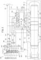
- the hydraulic hammering device includes a cylinder 100 and a piston 120 and, in conjunction therewith, is provided with a first control valve 200 and a second control valve 300 as separate bodies from the cylinder 100.
- a valve 201 is slidably fitted, and, inside the second control valve 300, a shared spool 320 is slidably fitted.
- a back head 500 is attached in the rear of the cylinder 100.
- the back head 500 is filled with high-pressure back head gas G.
- a front head 600 is attached in front of the cylinder 100. Inside the front head 600, a rod 601 is slidably fitted.
- the piston 120 is a solid cylindrical body and has, substantially in the middle thereof, a front-side large-diameter portion 121 and a rear-side large-diameter portion 122 as two large-diameter portions.
- a medium-diameter portion 123 is disposed in front of the front-side large-diameter portion 121
- a small-diameter portion 124 is disposed in the rear of the rear-side large-diameter portion 122
- an annular groove 125 is disposed between the front-side large-diameter portion 121 and the rear-side large-diameter portion 122.
- the piston 120 being slidably fitted inside the cylinder 100 causes a piston front chamber 101 and a piston rear chamber 102 to be defined on the front and rear sides in the cylinder 100, respectively.
- a front chamber port 103 is disposed to the piston front chamber 101, and the front chamber port 103 is constantly connected to a high pressure circuit 110 via a front chamber passage 112.
- a rear chamber port 104 is disposed to the piston rear chamber 102.
- the rear chamber port 104 and the first control valve 200 are connected to each other by a rear chamber passage 113.
- the piston rear chamber 102 is configured to be capable of alternately communicating with either the high pressure circuit 110 or a low pressure circuit 111 by means of switching of the valve 201 of the first control valve 200 between advancement and retraction. Note that, at an appropriate location along the high pressure circuit 110, an accumulator (not illustrated) is disposed.
- Outer diameter of the medium-diameter portion 123 is set larger than outer diameter of the small-diameter portion 124 .
- This causes, of pressure receiving areas of the piston 120 in the piston front chamber 101 and the piston rear chamber 102, that is, a diameter difference between the front-side large-diameter portion 121 and the medium-diameter portion 123 and a diameter difference between the rear-side large-diameter portion 122 and the small-diameter portion 124, one in the piston rear chamber 102 to have a larger value than the other.
- the piston 120 when the piston rear chamber 102 is connected to high pressure by actuation of the valve 201, the piston 120 is configured to advance due to the pressure receiving area difference, and, when the piston rear chamber 102 is connected to low pressure by actuation of the valve 201, the piston 120 is configured to retract.
- the hydraulic hammering device includes, in a selectable manner, an auto-stroke mechanism configured to make the piston 120 advance and retract in the cylinder 100 with a stroke automatically selected out of a regular stroke and a short stroke, which is shorter than the regular stroke, and thereby strike the rod 601 and an idle strike prevention mechanism configured to control, depending on an advanced or retracted position of the piston 120, whether pressurized oil supplied to the piston front chamber 101 is maintained at a starting pressure or higher or pressurized oil supplied to the piston front chamber 101 is set at a striking suspension pressure that exceeds an open pressure and is lower than the starting pressure.
- switching between the auto-stroke mechanism and the idle strike prevention mechanism is performed by operating a mode selection means 400.
- a stroke control port 105, a spool control port 106, a valve control port 107, and a low pressure port 108 are disposed at positions separated from one another in the axial direction between the front chamber port 103 and the rear chamber port 104.
- the first control valve 200 has a valve chamber 212 formed on the inside thereof, the valve chamber 212 being formed in a non-concentric manner with respect to the piston 120, and, in the valve chamber 212, a valve 201 is slidably fitted.
- the valve chamber 212 includes a valve front chamber 213 having a medium diameter, a valve main chamber 214 having a large diameter, and a valve rear chamber 215 having a small diameter in this order from the front to the rear.
- a front chamber passage 223 in constant communication with the high pressure circuit 110 is connected.
- a front-side low pressure port 218, a reset port 219, a valve control port 220 are disposed in this order from the front to the rear, and, to the valve rear chamber 215, a rear-side low pressure port 221 and a rear chamber port 222 are disposed.
- the front-side low pressure port 218 is in constant communication with the low pressure circuit 111 via a front-side low pressure passage 224
- the rear-side low pressure port 221 is in constant communication with the low pressure circuit 111 via a rear-side low pressure passage 227.
- the valve control port 220 and the valve control port 107 are in communication with each other via a valve control passage (direct connection) 114.
- the rear chamber port 222 and the rear chamber port 104 are in communication with each other via a rear chamber passage 113.
- the valve 201 is a hollow cylindrical body and includes a medium-diameter portion 202, a large-diameter portion 203, and a small-diameter portion 204 in this order from the front to the rear.
- a hollow passage 228 on the inner side of the cylinder is in constant communication with the high pressure circuit 110 via the front chamber passage 223.
- an oil discharge groove 205 for switching pressure in the piston rear chamber 102 between high pressure and low pressure is disposed in an annular manner on a substantially middle portion of the outer peripheral surface of the small-diameter portion 204.
- communication holes 210 are formed in a penetrating manner in radial directions of the valve 201, and, on a front-side portion of the outer peripheral surface of the large-diameter portion 203, slit grooves 211 are formed in slit shapes along the axial direction.
- the valve 201 of the present embodiment is constantly biased rearward due to a pressure receiving area difference between the medium-diameter portion 202 and the small-diameter portion 204 and is configured to, when high pressure oil is supplied to the valve control port 220, move forward because pressure receiving area of a rear-side stepped surface 209 of the large-diameter portion 203 is added to the pressure receiving area difference.
- valve 201 When the valve 201 reaches the rear end position, that is, when a rear end surface 207 thereof comes into contact with a valve chamber rear end surface 217, the piston rear chamber 102 is connected to low pressure because the oil discharge groove 205 causes the rear chamber port 222 to come into communication with the low pressure circuit 111 via the rear-side low pressure port 221 and the rear-side low pressure passage 227.
- the piston rear chamber 102 is configured to be connected to high pressure because the rear chamber port 222 has its communication with the rear-side low pressure port 221 cut off and, in conjunction therewith, comes into communication with the valve chamber 212, which is connected to high pressure, via a passage between the rear end surface 207 and the valve chamber rear end surface 217 and the hollow passage 228.
- valve 201 since the valve control port 220 has to be maintained at high pressure or low pressure, the valve 201 requires a retention mechanism for maintaining the valve 201 in a halting state at switching positions thereof at the front end and the rear end.
- the retention mechanism when the valve 201 is positioned at the rear end position is the slit grooves 211.
- the slit grooves 211 are configured to, by communicating the valve control port 220, the reset port 219, and the front-side low pressure port 218 with one another, surely connect the rear-side stepped surface 209 to low pressure and thereby maintain the halting state of the valve 201.
- the retention mechanism when the valve 201 is positioned at the front end position is the communication holes 210.
- the communication holes 210 are configured to, by replenishing the valve control port 220 (and the reset port 219) with pressurized oil from the hollow passage 228, prevent retention pressure from decreasing and thereby maintain the halting state of the valve 201.
- the hydraulic hammering device of the present embodiment includes the second control valve 300, which is disposed adjacent to the above-described first control valve 200 and on a side surface of the cylinder 100. Note that, in FIG. 1 , the second control valve 300 is illustrated at a position apart from the cylinder 100 and the first control valve 200 for the purpose of illustration.
- the second control valve 300 has a first sleeve 302a and a second sleeve 302b loaded in a substantially cuboid-shaped housing 301 and has a spool chamber 304 formed by the first sleeve 302a and the second sleeve 302b. Positions in the axial direction of the first sleeve 302a and the second sleeve 302b are fixed by screwing down a plug 303 that is screwed into an opening on an upper portion of the housing 301.
- the shared spool 320 being slidably fitted in the spool chamber 304 so as to be capable of moving in a sliding manner causes a high pressure chamber 305 and a control chamber 306 to be defined above and below the shared spool 320, respectively, and, in conjunction therewith, a decompression chamber 307 to be defined at a position between the high pressure chamber 305 and the control chamber 306.
- the shared spool 320 is a cylindrical member constituted by a large-diameter portion 321 and a small-diameter portion 322, and, on the outer periphery of the large-diameter portion 321, an annular communication groove 323 is disposed.
- a through-hole 324 is formed along the axis, and an orifice 325 is disposed on the large-diameter portion 321 side of the through-hole 324.
- lateral holes 326 are formed in the direction intersecting the axis at right angles. The lateral holes 326 are formed in such a way as to come into communication with the decompression chamber 307 via a gap 307a when the shared spool 320 moves to the lower end position.
- a high pressure port 308 configured to communicate with the high pressure chamber 305 is disposed and, in conjunction therewith, a control port 309 configured to communicate with the control chamber 306 and a decompression port 310 configured to communicate with the decompression chamber 307 are respectively disposed.
- a valve communication port 311 and a cylinder communication port 312 are disposed at positions facing the communication groove 323 and a low pressure port 313 is disposed at a position between the cylinder communication port 312 and the control port 309.
- the high pressure port 308 is in communication with the high pressure circuit 110 by way of a high pressure passage 314, and the high pressure chamber 305 is therefore constantly connected to high pressure.
- the control port 309 communicates with the spool control port 106 by way of a spool control passage 115 and, in conjunction therewith, communicates with the reset port 219 by way of a reset passage 225.
- a check valve 340 is disposed in such a way as to allow pressurized oil to flow from the reset port 219 side to the control port 309 side.
- the decompression port 310 is in communication with the low pressure circuit 111 by way of a decompression passage 315, and, to the decompression passage 315, a first switching valve 401 and a variable throttle 330 are disposed in this order from the decompression port 310 side to the low pressure circuit 111 side.
- the first switching valve 401 is a two-position electromagnetic switching valve the upper position of which is configured to allow communication and the lower position of which is configured to allow communication through a throttle 402.
- the first switching valve 401 is regularly switched to the lower position.
- the valve communication port 311 is in communication with the valve control port 220 by way of a valve control passage (via spool) 226.
- the cylinder communication port 312 is in communication with the stroke control port 105 by way of a stroke control passage 116.
- a second switching valve 403 is disposed to the stroke control passage 116.
- the second switching valve 403 is a two-position electromagnetic switching valve the upper position of which is configured to close a passage and the lower position of which is configured to allow communication and is regularly switched to the lower position.
- the low pressure port 313 is in communication with the low pressure circuit 111 by way of a low pressure passage 316.
- the first switching valve 401 and the second switching valve 403 correspond to a "mode selection means" described in the above-described solution to problem.
- the shared spool 320 when the control port 309 is supplied with high pressure oil, the shared spool 320 is configured to move to the upper side due to a pressure receiving area difference between the surfaces of the shared spool 320 in the control chamber 306 and the high pressure chamber 305 caused by a diameter difference between the large-diameter portion 321 and the small-diameter portion 322, and, when the control port 309 is under low pressure without being supplied with high pressure oil, the shared spool 320 is configured to move to the lower side as illustrated in FIG. 1 .
- the second control valve 300 is configured in such a way that, when the shared spool 320 moves to the lower side, the valve communication port 311 and the cylinder communication port 312 comes into communication with each other by way of the communication groove 323 and the stroke control port 105 and the valve control port 220 thereby comes into communication with each other and, when the shared spool 320 moves to the upper side, communication between the valve communication port 311 and the cylinder communication port 312 is cut off.
- a position to which the shared spool 320 moves to the upper side is also referred to as a "regular stroke position", and a position to which the shared spool 320 moves toward the lower side is also referred to as a “short stroke position”.
- a position to which the piston 120 advances by a predetermined amount beyond an impact point at the time of an advancing movement, as an advanced or retracted position of the piston 120 is also referred to as a "switch position".
- a flow rate adjustment amount ⁇ 1 by the throttle 402 is set in such a way that pressurized oil in the decompression chamber 307 is allowed to leak and flow out to the low pressure circuit 111.
- a flow rate adjustment amount ⁇ 2 by the variable throttle 330 is set in such a way that pressurized oil in the decompression chamber 307 is decompressed to a pressure lower than the starting pressure.
- a relationship between ⁇ 1 and ⁇ 2 is expressed by Formula 1 below. ⁇ 1 > ⁇ 2
- the decompression chamber 307 never exerts a decompression action even when the shared spool 320 moves toward the lower side. Since, meanwhile, movements of the shared spool 320 to the upper and lower sides cause the stroke control port 105 and the valve control port 220 to be connected and cut off from each other and, in conjunction therewith, the reset port 219 and the control port 309 to be connected to each other, the hydraulic hammering device is operated in accordance with an "auto-stroke specification".
- the decompression chamber 307 exerts a decompression action by means of the variable throttle 330 when the shared spool 320 moves toward the lower side. Since, meanwhile, even when the shared spool 320 moves to the upper and lower sides, the stroke control port 105 and the valve control port 220 are never connected to each other, the hydraulic hammering device is operated in accordance with an "idle strike prevention specification".
- the piston 120 When the hydraulic hammering device of the first embodiment is in a state in which the first switching valve 401 and the second switching valve 403 are switched to the regular positions, the piston 120 is, in a pre-operation state, pressed forward by pressing force F, which is generated by the high-pressure back head gas G filled in the back head 500, as illustrated in FIG. 1 . Thus, the piston 120 is positioned at a front dead point.
- the shared spool 320 of the second control valve 300 At the time of starting operation, when the piston 120 is positioned at the front dead point, in the shared spool 320 of the second control valve 300, the high pressure chamber 305 thereabove, illustrated in the drawing, is constantly connected to the front chamber passage 112 and the control chamber 306 therebelow is connected to the low pressure circuit 111. Thus, the shared spool 320 is pressed downward in the drawing and is positioned at the "short stroke position".
- the valve front chamber 213 is supplied with high pressure oil in the front chamber passage 112.
- the valve 201 is positioned at a retracted position.
- the first control valve 200 connects the piston rear chamber 102 to the low pressure circuit 111.
- the valve 201 moves forward with pressure receiving area of the rear-side stepped surface 209 added. Since this causes the rear chamber port 222 to come into communication with the valve chamber 212, which is connected to high pressure, via a passage between the rear end surface 207 of the valve 201 and the valve chamber rear end surface 217 and the hollow passage 228, the piston rear chamber 102 is connected to high pressure. Since the piston rear chamber 102 is thus brought to high pressure, the piston 120 starts to advance in a short stroke due to a pressure receiving area difference of the piston 120 itself.
- constituent elements disposed as means for supplying pressurized oil to the control port 309 of the second control valve 300 are the check valve 340, the reset passage 225, and the reset port 219.
- valve control port 220 and the reset port 219 come into communication with each other by way of the rear-side stepped surface 209 and pressurized oil is supplied from the reset passage 225 to the control port 309 of the second control valve 300 via the check valve 340.
- this causes the shared spool 320 to be pressed upward in the drawing due to a pressure receiving area difference between the small-diameter portion 322 and the large-diameter portion 321, which are upper and lower portions of the shared spool 320, respectively, and to be switched to the "regular stroke position".
- the reset port 219 is replenished with pressurized oil from the communication hole 210 via the valve control port 220.
- a sufficient amount of pressurized oil required for retention of a halting state of the valve 201 and operation of the shared spool 320 of the second control valve 300 (upward movement in the drawing and retention of a halting state after the movement of the shared spool 320) is supplied.
- valve control port 107 of the cylinder 100 keeps communicating with the low pressure port 108 until the piston 120 retracts and switching of the valve 201 is performed
- the valve control port 220 of the first control valve 200 keeps communicating with the low pressure port 108. Since this causes pressurized oil in the spool control port 106 of the cylinder 100 to be retained within a closed circuit, the shared spool 320 is retained at the "regular stroke position" lest the valve 201 is switched.
- the valve control port 107 comes into communication with high pressure oil in the piston front chamber 101.
- the high pressure oil is fed into the valve control port 220 of the first control valve 200 via the valve control port 107.
- the front end of the front-side large-diameter portion 121 passes, in a process of retracting to the valve control port 107, the stroke control port 105 and the spool control port 106 in this order, the operation of the hydraulic hammering device is not affected because circuits extending from both ports are closed.
- valve 201 of the first control valve 200 moves to the advanced position due to a pressure receiving area difference between the front and rear surfaces of the valve 201 and the rear chamber port 222 comes into communication with the valve chamber 212, which is connected to high pressure, via a passage between the rear end surface 207 of the valve 201 and the valve chamber rear end surface 217 and the hollow passage 228, the piston rear chamber 102 is connected to high pressure, bringing the piston rear chamber 102 to high pressure.
- the piston 120 starts to advance due to a pressure receiving area difference between the front and rear surfaces of the piston 120.
- the piston 120 When the bedrock is soft, the piston 120, after having struck the bedrock, further advances beyond the position of the impact point. On this occasion, in the hydraulic hammering device of the present embodiment, when the piston 120 further advances beyond the position of the impact point and the rear end of the front-side large-diameter portion 121 of the piston 120 reaches a "switching position", at which the spool control port 106 of the cylinder 100 is formed, the spool control port 106 comes into communication with the low pressure port 108 and is thereby connected to low pressure. Thus, high pressure oil in the control port 309 on the lower side of the second control valve 300 is released, causing the shared spool 320 of the second control valve 300 to be pressed downward and switched to the "short stroke position".
- valve 201 of the first control valve 200 is switched to the advanced position, in response to which the piston rear chamber 102 is brought to high pressure. Therefore, the piston 120 starts to advance in the short stroke due to the pressure receiving area difference between the front and rear surfaces of the piston 120 itself. That is, according to the hydraulic hammering device, when bedrock is soft, the second control valve 300 is switched to the "short stroke position" at the “switching position", enabling the piston 120 to automatically perform striking in the short stroke.
- valve 201 When the valve 201 is switched to the advanced position, operational pressurized oil of the valve 201, which is fed into the valve control port 220, is fed from the reset port 219 of the first control valve 200 into the control port 309 on the lower side of the second control valve 300 via the check valve 340 in the reset passage 225.
- the second control valve 300 is pressed upward in the drawing due to the pressure receiving area difference between the small-diameter portion 322 and the large-diameter portion 321, which are upper and lower portions of the shared spool 320, respectively, and is switched to the "regular stroke position". In other words, the second control valve 300 is reset from a short stroke state to a regular stroke state.
- the piston 120 While, thereafter, in the hydraulic hammering device, the piston 120, repeating advancing and retracting movements, strikes the rod 601 through collaboration among the piston 120, the first control valve 200, and the second control valve 300 according to hardness of bedrock when the hydraulic hammering device is set at the "auto-stroke specification", the piston 120 advances and retracts in the regular stroke when the bedrock is hard (that is, when the position of the piston 120 at the time of advancement does not reach the "switching position") and the piston 120 advances and retracts in the short stroke when the bedrock is soft (that is, when the position of the piston 120 at the time of advancement reaches the "switching position").
- the hydraulic hammering device when the hydraulic hammering device is set at the auto-stroke specification, automatically switching the stroke of the piston 120 to a stroke selected from the short stroke and the regular stroke depending on the hardness of the bedrock (the amount of penetration into the bedrock) and thereby appropriately adjusting striking power enables an excessive load on striking portions, such as the rod 601 and a rod pin, to be reduced.
- the stroke control port 105, the valve control port 107, and the spool control port 106 which is disposed at a position between the two ports 105 and 107, are disposed to the cylinder 100 and, while the high pressure chamber 305 at one end of the second control valve 300 is constantly set at high pressure, regarding the control chamber 306 at the other end of the second control valve 300, when the piston 120, at the time of advancement, reaches a position at which it is communicable with the spool control port 106, which coercively switches strokes, the second control valve 300 is switched to the "short stroke position" by communicating the control chamber 306 of the second control valve 300 with the low pressure circuit 111 and, in conjunction therewith, when the piston 120 retracts, the control chamber 306 is communicated with the front chamber passage 112 and the second control valve 300 is thereby switched to the "regular stroke position", at which the cylinder stroke is reset to the regular stroke, addition of the spool control port 106 to
- the hydraulic hammering device is influenced by change in temperature of hydraulic oil compared with, for example, a structure in which a throttle is disposed to the second control valve 300, it can be said that the second control valve 300 has high operational stability.
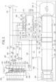
- the piston 120 When the hydraulic hammering device is in a state in which the first switching valve 401 and the second switching valve 403 are switched to the upper positions illustrated in FIG. 3 and is in a pre-operation state, the piston 120 is, as described above, pressed forward by the pressing force F, which is generated by the gas pressure of the back head gas G filled in the back head 500. Thus, the piston 120 is positioned at a front dead point illustrated in FIG. 3 .
- the high pressure chamber 305 thereabove, illustrated in the drawing constantly is connected to the front chamber passage 112 and the control chamber 306 therebelow is in communication with the spool control port 106 of the cylinder 100 via the spool control passage 115.
- pressurized oil supplied from the high pressure chamber 305 to the through-hole 324 at the center of the shared spool 320 leaks out to a tank via the spool control passage 115 and the spool control port 106. Therefore, the shared spool 320 is pressed downward in the drawing due to oil pressure on the high pressure chamber 305 side and is positioned at a "suspension control position".
- the valve 201 of the first control valve 200 is positioned at the retracted position.
- the first control valve 200 connects the piston rear chamber 102 to the low pressure circuit 111.
- the piston 120 is positioned at the front dead point by the forward pressing force F, generated by the back head gas G.
- the second control valve 300 moves to the lower side pressed by pressing force of pressurized oil working on the upper end surface of the shared spool 320.
- the pressurized oil supplied to the second control valve 300 is discharged from the decompression chamber 307, which is formed at the position of the small-diameter portion 322 of the shared spool 320, to the decompression passage 315 and is thereby decompressed.
- pressurized oil supplied to the through-hole 324 at the center of the shared spool 320 leeks out to the tank via the spool control passage 115, which is connected to the control port 309 on the lower side, and the spool control port 106.
- Diameter and capacity of the orifice 325 of the through-hole 324 and the decompression chamber 307 are set in such a way that pressure of supplied pressurized oil is set at a striking suspension pressure that is a pressure exceeding the open pressure and lower than the starting pressure.
- the striking suspension pressure is set at a value within a range from 5 MPa to 8 MPa.
- the oil pressure set at the striking suspension pressure which is a pressure exceeding the open pressure and lower than the starting pressure, works on the pressure receiving surface of the piston front chamber 101 against the forward pressing force F, generated by the back head gas G.
- the pushing-in operation of the rod 601 is performed by an operator pushing the rod 601 through manipulation of a boom, an arm, or the like of a platform truck.
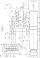
- the rod 601 being pushed in to the piston 120 side causes, as illustrated in FIG. 4 , the piston 120, pushed by the rod 601, to retract and the front-side large-diameter portion 121 of the piston 120 to cut off a communication state between the spool control port 106 and low pressure port 108 of the cylinder 100.
- the spool control port 106 is closed, pressure in the control chamber 306 below the shared spool 320 is raised because pressurized oil supplied to the high pressure chamber 305 above the shared spool 320 is supplied to the control chamber 306 via the through-hole 324 penetrating the center of the shared spool 320 and the orifice 325 at the lower end of the through-hole 324.
- the shared spool 320 is pushed upward by the pressurized oil due to the pressure receiving area difference between the small-diameter portion 322 and the large-diameter portion 321, which are upper and lower portions of the shared spool 320, respectively, and the shared spool 320 moves to the upper side and is positioned at a "regular striking position".
- the lateral holes 326 formed to the small-diameter portion 322, which is an upper portion of the shared spool 320 are shut off.
- pressure of pressurized oil in the front chamber passage 112 rises to the starting pressure or higher, the piston 120 retracts due to the starting pressure working on the pressure receiving surface of the piston 120 in the piston front chamber, and the hydraulic hammering device starts to operate.
- valve control port 220 When the valve control port 220 is connected to low pressure, the valve 201 of the first control valve 200 is pressed rearward due to the pressure receiving area difference between the front and rear surfaces of the valve 201 and switched to the retracted position, in response to which the piston rear chamber 102 is brought to low pressure.
- the piston 120 starts to retract even with a small amount of penetration when bedrock is hard.
- the shared spool 320 of the second control valve 300 is maintained at the "regular striking position".
- the hydraulic hammering device is capable of, when the bedrock is hard, performing continuous regular striking in which the piston 120, repeating advancing and retracting movements, strikes the rod 601.
- the piston 120 when the bedrock is soft, the piston 120, after having struck the bedrock, further advances beyond the position of the impact point.
- the spool control port 106 of the cylinder 100 when the piston 120 has further advanced beyond the position of the impact point and the rear end of the front-side large-diameter portion 121 of the piston 120 has reached the "suspension control position", at which the spool control port 106 of the cylinder 100 is formed, the spool control port 106 is connected to the low pressure circuit because of coming into communication with the low pressure port 108 via the annular groove 125.
- high pressure oil in the control port 309 below the shared spool 320 of the second control valve 300 is released.
- the shared spool 320 of the second control valve 300 is pressed downward by pressurized oil supplied to the high pressure chamber 305 and is switched to a "striking suspension position".
- the pressurized oil supplied to the high pressure chamber 305 of the second control valve 300 is discharged from the above-described decompression chamber 307 to the decompression passage 315.
- the front chamber passage 112 is decompressed and pressure of pressurized oil working on the pressure receiving surface of the piston 120 in the piston front chamber is thereby reduced to lower than the starting pressure, and the piston 120 moves to the front dead point by the forward pressing force F, generated by the back head gas G, and automatically stops.
- the hydraulic hammering device is capable of, when set at the "idle strike prevention specification", switching striking operation of the piston 120 depending on hardness of bedrock (the amount of penetration into the bedrock) in such a way as to perform continuous regular strikes when the bedrock is hard and to automatically stop the piston 120 when the bedrock is soft.
- the hydraulic hammering device is capable of, when set at the idle strike prevention specification, stopping the piston 120 while the piston front chamber 101 exerts a cushioning action when the piston 120 is to be stopped at the position of the front dead point at the time of striking cycle suspension because pressure in the piston front chamber 101 is set at the striking suspension pressure of approximately 5 to 8 MPa, which exceeds the open pressure and is lower than the starting pressure. Since, thus, the piston 120 is prevented or suppressed from colliding against the front head 600 with great force, loads on both at the time of striking cycle suspension are reduced.
- the hydraulic hammering device since pressure of the pressurized oil working on the pressure receiving surface of the piston 120 in the piston front chamber is set at the striking suspension pressure of approximately 5 to 8 MPa when the piston 120 is positioned at the position of the front dead point, the hydraulic hammering device is capable of pushing in the rod 601 to the impact point with small power when the striking cycle is resumed and easily cutting off the communication state between the spool control port 106 of the cylinder and the low pressure port 108 of the cylinder 100.
- a cancel operation of the idle strike prevention specification is easy to perform.
- the hydraulic hammering device since the hydraulic hammering device is configured in a simple structure in which the spool control port 106 is added to the cylinder 100 and enables striking operation of the piston 120 to be switched through simple switching of oil passages depending on the position of the piston 120, which represents the amount of penetration into bedrock, it can be said that operation of the second control valve 300 has high stability.
- the second embodiment differs from the first embodiment in not including the mode selection means 400 as a switching valve and in that replacing, as a spool slidably fitted into a second control valve, a spool in accordance with an auto-stroke specification and a spool in accordance with an idle strike prevention specification with each other switches both modes.
- FIGS. 5 and 6 illustrate states in which an auto-stroke spool 350 is slidably fitted into a second control valve 300' .
- the auto-stroke spool 350 is a cylindrical member having a large-diameter portion 351 and a small-diameter portion 352, and, on the outer periphery of the large-diameter portion 351, an annular communication groove 353 is disposed.
- the communication groove 353 is formed in such a way as to communicate a valve communication port 311 and a cylinder communication port 312 with each other when the auto-stroke spool 350 moves to the lower end position.
- a configuration of the other portion of the second control valve 300' is the same as that of the second control valve 300 of the first embodiment. Note that, in the case of the second control valve 300', since there is no possibility that a decompression chamber 307 communicates with a high pressure chamber 305, a decompression port 310 and a decompression passage 315 do not work as a decompression mechanism but function as a drain.
- FIGS. 7 and 8 illustrate states in which an idle strike prevention spool 360 is slidably fitted into a second control valve 300".
- the idle strike prevention spool 360 is a cylindrical member having a large-diameter portion 361 and a small-diameter portion 362, and, at the axis thereof, a through-hole 363 is formed along the axis.
- an orifice 364 is disposed, and, on the small-diameter portion 362 side of the through-hole 363, lateral holes 365 are formed in the direction intersecting the axis at right angles.
- the lateral holes 365 are formed in such a way as to come into communication with the decompression chamber 307 via a gap 307a when the idle strike prevention spool 360 moves to the lower end position.
- the idle strike prevention spool 360 differs from the shared spool 320 in the first embodiment in that the communication groove 323 in the first embodiment is not formed on the outer periphery of the large-diameter portion 361.
- a configuration of the other portion of the second control valve 300' ' is the same as that of the second control valve 300 of the first embodiment. Note that, in the case of the second control valve 300", since there is no possibility that a valve communication port 311 and a cylinder communication port 312 come into communication with each other because the communication groove 323 in the first embodiment is not formed, a stroke control passage 116 and a valve control passage (via spool) 226 do not work as an auto-stroke mechanism.
- replacement work of the auto-stroke spool 350 and the idle strike prevention spool 360 can be performed only by removing a plug 303 and a first sleeve 302a. Therefore, it is possible to change the auto-stroke specification into the idle strike prevention specification and vice versa appropriately and easily, on an as-needed basis.
Landscapes
- Engineering & Computer Science (AREA)
- Mechanical Engineering (AREA)
- Physics & Mathematics (AREA)
- Fluid Mechanics (AREA)
- Mining & Mineral Resources (AREA)
- Automation & Control Theory (AREA)
- Life Sciences & Earth Sciences (AREA)
- General Life Sciences & Earth Sciences (AREA)
- Geochemistry & Mineralogy (AREA)
- Geology (AREA)
- Fluid-Pressure Circuits (AREA)
- Percussive Tools And Related Accessories (AREA)
- Earth Drilling (AREA)
Claims (2)
- Dispositif de percussion hydraulique, comprenant :un cylindre (100) ;un piston (120) configuré pour être monté de manière coulissante dans le cylindre (100) de manière à pouvoir avancer et se rétracter ;une première soupape de commande (200) configurée pour commander des mouvements d'avancée et de rétractation du piston (120) ;un mécanisme de course automatique configuré pour commuter une course de piston (120) du piston (120) entre une course régulière et une course courte plus courte que la course régulière ;un mécanisme de prévention de frappe au ralenti configuré pour décompresser l'intérieur d'un circuit configuré pour entraîner hydrauliquement le piston (120) à moins qu'une pression de travail ; etcaractérisé par une seconde soupape de commande (300) configurée pour sélectionner un mode parmi le mécanisme de course automatique et le mécanisme de prévention de frappe au ralenti,dans lequel, une bobine partagée (320) incluant une partie de réglage de course automatique et une partie de réglage de prévention de frappe au ralenti en même temps est montée de manière coulissante sur la seconde soupape de commande (300), etun moyen de sélection de mode (400) est disposé pour autoriser et couper à la fois l'alimentation en huile sous pression de la partie de réglage de course automatique et la décharge d'huile sous pression depuis la partie de réglage de prévention de frappe au ralenti, etle moyen de sélection de mode (400) est configuré de telle manière que :lorsque de l'huile sous pression peut être fournie à la partie de réglage de course automatique mais de l'huile sous pression ne peut pas être déchargée de la partie de réglage de prévention de frappe au ralenti, le mécanisme de course automatique est sélectionné, etlorsque de l'huile sous pression ne peut pas être fournie à la partie de réglage de course automatique, mais de l'huile sous pression peut être déchargée à partir de la partie de réglage de prévention de frappe au ralenti, le mécanisme de prévention de frappe au ralenti est sélectionné.
- Dispositif de percussion hydraulique, comprenant :un cylindre (100) ;un piston (120) configuré pour être monté de manière coulissante dans le cylindre (100) de manière à pouvoir avancer et se rétracter ;une première soupape de commande (200) configurée pour commander des mouvements d'avancée et de rétractation du piston (120) ;un mécanisme de course automatique configuré pour commuter une course de piston (120) du piston (120) entre une course régulière et une course courte plus courte que la course régulière ;un mécanisme de prévention de frappe au ralenti configuré pour décompresser l'intérieur d'un circuit configuré pour entraîner hydrauliquement le piston (120) à moins qu'une pression de travail ; etcaractérisé par une seconde soupape de commande (300) configurée pour sélectionner un mode parmi le mécanisme de course automatique et le mécanisme de prévention de frappe au ralenti,dans lequel la seconde soupape de commande (300) inclut une partie de montage coulissant de bobine dans laquelle, en tant que bobine pour sélectionner un mode, une bobine pour course automatique (350) ou une bobine pour prévention de frappe au ralenti (360) est configurée pour être montée de manière coulissante de manière remplaçable, etlorsque la bobine pour course automatique (350) est montée de manière coulissante dans la partie de montage coulissant de la bobine, le mécanisme de course automatique est sélectionné, et, lorsque la bobine pour la prévention de frappe au ralenti (360) est montée de manière coulissante dans la partie de montage coulissant de la bobine, le mécanisme de prévention de frappe au ralenti est sélectionné.
Applications Claiming Priority (2)
| Application Number | Priority Date | Filing Date | Title |
|---|---|---|---|
| JP2017142789 | 2017-07-24 | ||
| PCT/JP2018/027543 WO2019022021A1 (fr) | 2017-07-24 | 2018-07-23 | Dispositif de percussion hydraulique |
Publications (3)
| Publication Number | Publication Date |
|---|---|
| EP3659752A1 EP3659752A1 (fr) | 2020-06-03 |
| EP3659752A4 EP3659752A4 (fr) | 2020-07-29 |
| EP3659752B1 true EP3659752B1 (fr) | 2023-04-19 |
Family
ID=65039723
Family Applications (1)
| Application Number | Title | Priority Date | Filing Date |
|---|---|---|---|
| EP18837343.5A Active EP3659752B1 (fr) | 2017-07-24 | 2018-07-23 | Dispositif de percussion hydraulique |
Country Status (8)
| Country | Link |
|---|---|
| US (2) | US11590642B2 (fr) |
| EP (1) | EP3659752B1 (fr) |
| JP (1) | JP7210452B2 (fr) |
| KR (1) | KR102593990B1 (fr) |
| CN (1) | CN110944801B (fr) |
| ES (1) | ES2945157T3 (fr) |
| FI (1) | FI3659752T3 (fr) |
| WO (1) | WO2019022021A1 (fr) |
Families Citing this family (5)
| Publication number | Priority date | Publication date | Assignee | Title |
|---|---|---|---|---|
| JP7359584B2 (ja) * | 2019-07-23 | 2023-10-11 | 古河ロックドリル株式会社 | 液圧式打撃装置 |
| JP7390940B2 (ja) * | 2020-03-12 | 2023-12-04 | 古河ロックドリル株式会社 | 液圧式打撃装置 |
| JP7431067B2 (ja) * | 2020-03-13 | 2024-02-14 | 古河ロックドリル株式会社 | 液圧式打撃装置 |
| JP7460491B2 (ja) | 2020-09-15 | 2024-04-02 | 古河ロックドリル株式会社 | 液圧式打撃装置 |
| EP4204197A1 (fr) * | 2020-12-31 | 2023-07-05 | Inan Makina Sanayi Ve Ticaret Anonim Sirketi | Brise-roche hydraulique avec système anti coups à vide |
Family Cites Families (104)
| Publication number | Priority date | Publication date | Assignee | Title |
|---|---|---|---|---|
| GB1114234A (en) * | 1963-12-21 | 1968-05-22 | Davy & United Eng Co Ltd | Control systems |
| US3699675A (en) * | 1971-04-05 | 1972-10-24 | Hughes Tool Co | Hydraulic impactor methods and apparatus |
| US3887019A (en) * | 1971-05-11 | 1975-06-03 | Af Hydraulics | Hydraulic percussive implement |
| US3774502A (en) * | 1971-05-14 | 1973-11-27 | Krupp Gmbh | Hydraulic percussion device with pressure-responsive control of impact frequency |
| US3759335A (en) * | 1971-12-30 | 1973-09-18 | Bell Lab Inc | Mole hammer-cycle control |
| US3827507A (en) * | 1972-09-18 | 1974-08-06 | Technology Inc Const | Hydraulically powered demolition device |
| US3971448A (en) * | 1973-09-04 | 1976-07-27 | The Stanley Works | Breaker construction and valve therefor |
| US3916764A (en) * | 1974-02-11 | 1975-11-04 | Ackley Manufacturing Co | Concrete breaker construction and valve mechanism |
| FR2250014A1 (fr) * | 1973-11-07 | 1975-05-30 | Secoma | |
| GB1480753A (en) * | 1974-11-14 | 1977-07-27 | Hydraulics Ltd A | Hydraulically-operated devices |
| US4342255A (en) * | 1976-06-09 | 1982-08-03 | Mitsui Engineering And Shipbuilding Co., Ltd. | Oscillator actuated hydraulic impulse device |
| FR2429320A1 (fr) * | 1978-06-20 | 1980-01-18 | Secoma | Appareil de foration hydraulique roto-percutant |
| CH638587A5 (de) * | 1979-02-12 | 1983-09-30 | Uster Spindel Motoren Maschf | Schlagbohrhammer. |
| US4354797A (en) * | 1979-05-31 | 1982-10-19 | Hitachi Construction Machinery Co., Ltd. | Front loading hydraulic excavator |
| US4347869A (en) * | 1979-12-14 | 1982-09-07 | American Standard Inc. | Hydraulic valve position control system for regulating smokestack exhaust pressure |
| US4474248A (en) * | 1981-04-23 | 1984-10-02 | Giovanni Donadio | Hydraulic demolishing rock drill |
| US4524582A (en) * | 1983-03-31 | 1985-06-25 | Cincinnati Incorporated | Control system for hydraulic presses |
| SE442434B (sv) * | 1983-04-11 | 1985-12-23 | Mecman Ab | Styrventil for kontrollerad tryckmedietillforsel till och tryckuppbyggnad i ett tryckmediesystem |
| US4527959A (en) * | 1983-05-10 | 1985-07-09 | Whiteman Manufacturing Company | Drilling fluid pump providing a uniform, controlled pressure and flow rate |
| DE3443542A1 (de) * | 1984-11-29 | 1986-06-05 | Fried. Krupp Gmbh, 4300 Essen | Hydraulische schlagvorrichtung |
| FR2595972B2 (fr) * | 1985-07-16 | 1989-10-20 | Montabert Ets | Appareil a percussions |
| EP0245572B1 (fr) * | 1985-11-04 | 1992-04-08 | Quarry Engineering Developments Pty. Ltd. | Dispositif de concassage de la roche |
| EP0236721A3 (fr) * | 1986-03-11 | 1989-10-25 | NITTETSU JITSUGYO CO., Ltd. | Concasseur hydraulique |
| FR2602448B1 (fr) * | 1986-08-07 | 1988-10-21 | Montabert Ets | Procede de regulation des parametres de percussion du piston de frappe d'un appareil mu par un fluide incompressible sous pression, et appareil pour la mise en oeuvre de ce procede |
| JPH0513509Y2 (fr) * | 1986-09-09 | 1993-04-09 | ||
| FR2618092B1 (fr) * | 1987-07-17 | 1989-11-10 | Montabert Ets | Distributeur hydraulique pour appareil a percussions mu par un fluide incompressible sous pression |
| US5279122A (en) * | 1989-08-16 | 1994-01-18 | Kabushiki Kaisha Komatsu Seisakusho | Hydraulic circuit apparatus for supplying fluid under pressure into hydraulic cylinders for work implement |
| US5060734A (en) * | 1989-09-11 | 1991-10-29 | United States Of America | Seawater hydraulic rock drill |
| JPH03208215A (ja) * | 1990-01-10 | 1991-09-11 | Izumi Seiki Seisakusho:Kk | 油圧式ブレーカー |
| JP2877977B2 (ja) | 1991-03-27 | 1999-04-05 | 古河機械金属株式会社 | 液圧式打撃機構 |
| FR2676953B1 (fr) * | 1991-05-30 | 1993-08-20 | Montabert Ets | Appareil hydraulique a percussions. |
| DE4229590C2 (de) * | 1992-09-04 | 1996-06-20 | Klemm Guenter | Hydraulisches Schlaggerät mit Vorsteuerventil |
| DE4400760C2 (de) * | 1994-01-13 | 1997-03-27 | Festo Kg | Mehrwegeventil |
| DE59409798D1 (de) * | 1994-02-19 | 2001-08-16 | Klemm Guenter | Hydraulischer Schlaghammer |
| US5626068A (en) * | 1994-04-12 | 1997-05-06 | White Manufacturing (Proprietary) Limited | Hydraulic reciprocating mechanism |
| FI941689A7 (fi) * | 1994-04-13 | 1995-10-14 | Doofor Oy | Menetelmä ja poralaite poranterään välitettävän iskupulssin muodon sovittamiseksi |
| FI104959B (fi) * | 1994-06-23 | 2000-05-15 | Sandvik Tamrock Oy | Hydraulinen iskuvasara |
| JPH0868076A (ja) * | 1994-08-29 | 1996-03-12 | Hitachi Constr Mach Co Ltd | 油圧ショベルのブレーカ制御装置 |
| FR2727891B1 (fr) * | 1994-12-08 | 1997-01-24 | Montabert Ets | Procede et appareil pour la regulation de la course de frappe d'un appareil a percussion mu par un fluide incompressible sous pression |
| JPH08281571A (ja) * | 1995-04-14 | 1996-10-29 | Komatsu Ltd | 振動発生装置 |
| FI104960B (fi) | 1995-07-06 | 2000-05-15 | Sandvik Tamrock Oy | Hydraulinen iskuvasara |
| JP3672978B2 (ja) | 1995-09-14 | 2005-07-20 | 古河機械金属株式会社 | 液圧式打撃機構 |
| FI104961B (fi) * | 1996-07-19 | 2000-05-15 | Sandvik Tamrock Oy | Painenestekäyttöinen iskuvasara |
| JPH1080878A (ja) | 1996-09-05 | 1998-03-31 | Furukawa Co Ltd | 液圧式打撃装置 |
| JP3724758B2 (ja) * | 1996-12-05 | 2005-12-07 | 株式会社小松製作所 | 切換バルブ装置 |
| US5836400A (en) * | 1997-11-18 | 1998-11-17 | Tupper; Myron D. | Three speed circuit for hydraulic tool |
| FI107891B (fi) * | 1998-03-30 | 2001-10-31 | Sandvik Tamrock Oy | Painenestekäyttöinen iskulaite |
| JP2000326261A (ja) * | 1999-05-13 | 2000-11-28 | Mazda Earth Technologies Co Ltd | 液圧式打撃装置 |
| DE10013270A1 (de) * | 2000-03-17 | 2001-09-20 | Krupp Berco Bautechnik Gmbh | Fluidbetriebenes Schlagwerk |
| US6491114B1 (en) * | 2000-10-03 | 2002-12-10 | Npk Construction Equipment, Inc. | Slow start control for a hydraulic hammer |
| DE10102409A1 (de) * | 2001-01-15 | 2002-07-25 | Hydac Fluidtechnik Gmbh | Steuervorrichtung für eine an einen hydraulischen Kreis angeschlossene Arbeitseinrichtung |
| DE10123202A1 (de) * | 2001-05-12 | 2002-11-14 | Krupp Berco Bautechnik Gmbh | Verfahren und Vorrichtung zur Absicherung eines fluidbetriebenen Schlagwerks gegen Leerschläge |
| JP3986803B2 (ja) * | 2001-11-20 | 2007-10-03 | 古河機械金属株式会社 | 液圧式打撃装置のストローク調整機構 |
| JP3967182B2 (ja) | 2002-04-17 | 2007-08-29 | 古河機械金属株式会社 | 液圧式打撃装置のストローク調整機構 |
| JP3976187B2 (ja) * | 2002-11-20 | 2007-09-12 | 株式会社マキタ | ハンマードリル |
| FI116513B (fi) * | 2003-02-21 | 2005-12-15 | Sandvik Tamrock Oy | Iskulaite |
| FI114290B (fi) * | 2003-02-21 | 2004-09-30 | Sandvik Tamrock Oy | Ohjausventtiili ja järjestely iskulaitteessa |
| FI115451B (fi) * | 2003-07-07 | 2005-05-13 | Sandvik Tamrock Oy | Iskulaite ja menetelmä jännityspulssin muodostamiseksi iskulaitteessa |
| JP2005177899A (ja) * | 2003-12-17 | 2005-07-07 | Konan Electric Co Ltd | 液圧式打撃装置 |
| SE528033C2 (sv) * | 2004-03-12 | 2006-08-15 | Atlas Copco Constr Tools Ab | Hydraulslagverk |
| DE102004035306A1 (de) * | 2004-07-21 | 2006-03-16 | Atlas Copco Construction Tools Gmbh | Druckmittelbetriebene Schlagvorrichtung insbesondere Hydraulikhammer |
| SE527921C2 (sv) * | 2004-10-20 | 2006-07-11 | Atlas Copco Rock Drills Ab | Slagverk |
| SE528745C2 (sv) * | 2005-06-22 | 2007-02-06 | Atlas Copco Rock Drills Ab | Ventilanordning för slagverk och slagverk för bergborrmaskin |
| FR2902684B1 (fr) * | 2006-06-27 | 2010-02-26 | Montabert Roger | Procede de commutation de la course de frappe d'un appareil a percussions mu par un fluide incompressible sous pression, et appareil pour la mise en oeuvre de ce procede |
| SE530885C2 (sv) * | 2007-02-23 | 2008-10-07 | Atlas Copco Rock Drills Ab | Förfarande vid slagverk, slagverk och bergborrmaskin |
| FI123634B (fi) * | 2007-10-05 | 2013-08-30 | Sandvik Mining & Constr Oy | Kallionrikkomislaite, suojaventtiili sekä menetelmä kallionrikkomislaitteen käyttämiseksi |
| KR100966740B1 (ko) * | 2007-11-26 | 2010-06-29 | 대모 엔지니어링 주식회사 | 투 스트로크 밸브가 장착된 유압브레이커 |
| SE531860C2 (sv) * | 2007-12-21 | 2009-08-25 | Atlas Copco Rock Drills Ab | Impulsalstrande anordning för inducering av en stötvåg i ett verktyg samt bergborrningsrigg innefattande sådan anordning |
| CN101403217B (zh) * | 2008-11-14 | 2010-06-02 | 中南大学 | 可无级调节冲击能和频率的液压打桩锤气液控制驱动系统 |
| US8640787B2 (en) * | 2009-12-30 | 2014-02-04 | Daniel F. Rohrer | Portable post driving apparatus |
| JP2013233595A (ja) * | 2010-08-27 | 2013-11-21 | Teisaku:Kk | 流体圧式打撃装置 |
| US8733468B2 (en) * | 2010-12-02 | 2014-05-27 | Caterpillar Inc. | Sleeve/liner assembly and hydraulic hammer using same |
| US8939227B2 (en) * | 2010-12-23 | 2015-01-27 | Caterpillar Inc. | Pressure protection valve for hydraulic tool |
| US9157253B2 (en) * | 2011-08-29 | 2015-10-13 | Daniel F. Rohrer, JR. | Portable driving device |
| FR2983760B1 (fr) | 2011-12-09 | 2014-08-15 | Montabert Roger | Procede de commutation de la course de frappe d'un piston de frappe d’un appareil a percussions |
| US9291161B2 (en) * | 2012-10-02 | 2016-03-22 | James Victor Hogan | Compact linear actuator |
| US9803388B2 (en) * | 2013-03-15 | 2017-10-31 | Striker Tools | Pneumatic post driver |
| ES2703124T3 (es) * | 2013-12-18 | 2019-03-07 | Nippon Pneumatic Mfg | Herramienta accionada por impacto |
| CN105916634B (zh) * | 2014-01-30 | 2017-08-25 | 古河凿岩机械有限公司 | 液压式冲击装置 |
| JP6480201B2 (ja) * | 2014-01-30 | 2019-03-06 | 古河ロックドリル株式会社 | 液圧式打撃装置 |
| US20150273676A1 (en) * | 2014-03-27 | 2015-10-01 | Michael B. Spektor | Optimized pneumatic hammer |
| US9701003B2 (en) * | 2014-05-23 | 2017-07-11 | Caterpillar Inc. | Hydraulic hammer having delayed automatic shutoff |
| DE102014108848A1 (de) | 2014-06-25 | 2015-12-31 | Construction Tools Gmbh | Vorrichtung zur Drucküberwachung |
| DE102014108849B9 (de) * | 2014-06-25 | 2022-12-22 | Construction Tools Gmbh | Drucküberwachungsvorrichtung |
| EP2963230B1 (fr) * | 2014-07-03 | 2017-05-31 | Sandvik Mining and Construction Oy | Dispositif de rupture |
| KR101638451B1 (ko) | 2014-07-30 | 2016-07-25 | 대모 엔지니어링 주식회사 | 무단 가변 자동 스트로크 유압 브레이커 시스템 |
| EP2987947B1 (fr) * | 2014-08-19 | 2018-01-31 | Doofor Oy | Vanne d'un dispositif de frappe hydraulique |
| ES2668312T3 (es) * | 2014-08-19 | 2018-05-17 | Doofor Oy | Válvula de un dispositivo hidráulico de percusión |
| US9840000B2 (en) * | 2014-12-17 | 2017-12-12 | Caterpillar Inc. | Hydraulic hammer having variable stroke control |
| US20160199969A1 (en) * | 2015-01-12 | 2016-07-14 | Caterpillar Inc. | Hydraulic hammer having variable stroke control |
| US11052524B2 (en) * | 2015-07-13 | 2021-07-06 | Furukawa Rock Drill Co., Ltd. | Hydraulic hammering device |
| AU2016303502B2 (en) | 2015-07-31 | 2019-10-31 | Tei Rock Drills, Inc. | Remote control of stroke and frequency of percussion apparatus and methods thereof |
| US10245714B2 (en) * | 2015-11-13 | 2019-04-02 | Caterpillar Inc. | Hydraulic buffer with fast startup |
| FR3044572B1 (fr) * | 2015-12-02 | 2017-12-29 | Montabert Roger | Dispositif brise roches |
| CN105507318A (zh) * | 2016-01-21 | 2016-04-20 | 杨林 | 一种新型高效打桩装置 |
| CN105626246A (zh) * | 2016-01-21 | 2016-06-01 | 杨炳 | 一种具有优化控制系统的建筑用打夯装置 |
| US10207379B2 (en) * | 2016-01-21 | 2019-02-19 | Colibri Spindles Ltd. | Live tool collar having wireless sensor |
| KR101782535B1 (ko) * | 2016-01-28 | 2017-10-24 | 대모 엔지니어링 주식회사 | 유압브레이커 |
| US10377028B2 (en) | 2016-03-14 | 2019-08-13 | Caterpillar Inc. | Hammer protection system and method |
| US10189153B2 (en) * | 2016-03-25 | 2019-01-29 | Sonny Frank | Leveling device assembly for a hydraulic hammer |
| US10562165B2 (en) * | 2016-04-10 | 2020-02-18 | Caterpillar Inc. | Hydraulic hammer |
| JP7028772B2 (ja) * | 2016-06-28 | 2022-03-02 | 古河ロックドリル株式会社 | 2ピストン型油圧打撃装置 |
| KR101780154B1 (ko) * | 2016-07-27 | 2017-09-20 | 대모 엔지니어링 주식회사 | 유압식 타격 기기 및 이를 포함하는 건설 장비 |
| KR101709673B1 (ko) * | 2016-12-13 | 2017-03-09 | 대모 엔지니어링 주식회사 | 2단 오토스트로크 유압 브레이커 |
-
2018
- 2018-07-23 JP JP2019532605A patent/JP7210452B2/ja active Active
- 2018-07-23 FI FIEP18837343.5T patent/FI3659752T3/fi active
- 2018-07-23 US US16/633,553 patent/US11590642B2/en active Active
- 2018-07-23 WO PCT/JP2018/027543 patent/WO2019022021A1/fr not_active Ceased
- 2018-07-23 CN CN201880048102.7A patent/CN110944801B/zh active Active
- 2018-07-23 EP EP18837343.5A patent/EP3659752B1/fr active Active
- 2018-07-23 KR KR1020207001912A patent/KR102593990B1/ko active Active
- 2018-07-23 ES ES18837343T patent/ES2945157T3/es active Active
-
2021
- 2021-11-08 US US17/521,044 patent/US12070844B2/en active Active
Also Published As
| Publication number | Publication date |
|---|---|
| CN110944801B (zh) | 2023-06-30 |
| WO2019022021A1 (fr) | 2019-01-31 |
| JP7210452B2 (ja) | 2023-01-23 |
| KR102593990B1 (ko) | 2023-10-24 |
| ES2945157T3 (es) | 2023-06-28 |
| CN110944801A (zh) | 2020-03-31 |
| US20210086337A1 (en) | 2021-03-25 |
| US12070844B2 (en) | 2024-08-27 |
| FI3659752T3 (fi) | 2023-05-04 |
| JPWO2019022021A1 (ja) | 2020-05-28 |
| EP3659752A1 (fr) | 2020-06-03 |
| US20220055196A1 (en) | 2022-02-24 |
| KR20200033854A (ko) | 2020-03-30 |
| EP3659752A4 (fr) | 2020-07-29 |
| US11590642B2 (en) | 2023-02-28 |
Similar Documents
| Publication | Publication Date | Title |
|---|---|---|
| US12070844B2 (en) | Hydraulic hammering device | |
| EP3100829B1 (fr) | Dispositif de martelage hydraulique | |
| EP2655753B1 (fr) | Valve de pression de protection pour outil hydraulique et procédé de déactivation d'un outil hydraulique | |
| KR20150113010A (ko) | 가변용적 축압기 | |
| JP6713853B2 (ja) | 液圧式打撃装置 | |
| KR101592445B1 (ko) | 3단 가변 자동 스트로크 유압 브레이커 | |
| EP3145677A1 (fr) | Marteau hydraulique ayant un arrêt automatique retardé | |
| JP6713778B2 (ja) | 液圧式打撃装置 | |
| CN104653529B (zh) | 凿岩台车的防溶洞卡钎系统 | |
| JP2021016931A (ja) | 液圧式打撃装置 | |
| KR100510966B1 (ko) | 유압브레이커의 공타방지장치 | |
| US10094754B2 (en) | Pressure indicator for hydraulic hammer | |
| EP3660224A1 (fr) | Dispositif de frappe hydraulique | |
| US7748309B2 (en) | Axle locking cylinder structure for heavy construction equipment | |
| KR20160062437A (ko) | 자체 증압이 가능한 유압실린더 | |
| EP3508308B1 (fr) | Dispositif de percussion hydraulique | |
| JPH10184262A (ja) | 流体式打撃機構 | |
| EP2789440A1 (fr) | Séparateur | |
| KR20240032406A (ko) | 자동 또는 수동 행정거리 전환기능이 구비된 유압 브레이커 및 이를 이용하는 유압 브레이커의 행정거리 모드전환 제어방법 | |
| JP2000326261A (ja) | 液圧式打撃装置 | |
| JP7057171B2 (ja) | 液圧式打撃装置 | |
| JP2021142621A (ja) | 液圧式打撃装置 | |
| JP7460491B2 (ja) | 液圧式打撃装置 | |
| KR20230056345A (ko) | 승압기를 구비한 유압 실린더 | |
| KR20120139434A (ko) | 가변형 저압 및 고압력 유압실린더 장치 |
Legal Events
| Date | Code | Title | Description |
|---|---|---|---|
| STAA | Information on the status of an ep patent application or granted ep patent |
Free format text: STATUS: THE INTERNATIONAL PUBLICATION HAS BEEN MADE |
|
| PUAI | Public reference made under article 153(3) epc to a published international application that has entered the european phase |
Free format text: ORIGINAL CODE: 0009012 |
|
| STAA | Information on the status of an ep patent application or granted ep patent |
Free format text: STATUS: REQUEST FOR EXAMINATION WAS MADE |
|
| 17P | Request for examination filed |
Effective date: 20200123 |
|
| AK | Designated contracting states |
Kind code of ref document: A1 Designated state(s): AL AT BE BG CH CY CZ DE DK EE ES FI FR GB GR HR HU IE IS IT LI LT LU LV MC MK MT NL NO PL PT RO RS SE SI SK SM TR |
|
| AX | Request for extension of the european patent |
Extension state: BA ME |
|
| A4 | Supplementary search report drawn up and despatched |
Effective date: 20200626 |
|
| RIC1 | Information provided on ipc code assigned before grant |
Ipc: B25D 9/20 20060101ALI20200622BHEP Ipc: B25D 17/10 20060101ALI20200622BHEP Ipc: E21C 27/12 20060101ALI20200622BHEP Ipc: B25D 9/18 20060101ALI20200622BHEP Ipc: B25D 9/26 20060101AFI20200622BHEP |
|
| DAV | Request for validation of the european patent (deleted) | ||
| DAX | Request for extension of the european patent (deleted) | ||
| RIC1 | Information provided on ipc code assigned before grant |
Ipc: B25D 9/20 20060101ALI20220805BHEP Ipc: B25D 9/18 20060101ALI20220805BHEP Ipc: E21C 27/12 20060101ALI20220805BHEP Ipc: B25D 17/10 20060101ALI20220805BHEP Ipc: B25D 9/26 20060101AFI20220805BHEP |
|
| GRAP | Despatch of communication of intention to grant a patent |
Free format text: ORIGINAL CODE: EPIDOSNIGR1 |
|
| STAA | Information on the status of an ep patent application or granted ep patent |
Free format text: STATUS: GRANT OF PATENT IS INTENDED |
|
| INTG | Intention to grant announced |
Effective date: 20221122 |
|
| RIN1 | Information on inventor provided before grant (corrected) |
Inventor name: NAGANO, SHINSUKE Inventor name: SHIODA, ATSUSHI Inventor name: KOBAYASHI, ISAO Inventor name: MURAKAMI, SUSUMU Inventor name: KANEKO, TSUTOMU |
|
| GRAS | Grant fee paid |
Free format text: ORIGINAL CODE: EPIDOSNIGR3 |
|
| GRAA | (expected) grant |
Free format text: ORIGINAL CODE: 0009210 |
|
| STAA | Information on the status of an ep patent application or granted ep patent |
Free format text: STATUS: THE PATENT HAS BEEN GRANTED |
|
| RAP3 | Party data changed (applicant data changed or rights of an application transferred) |
Owner name: FURUKAWA ROCK DRILL CO., LTD. |
|
| AK | Designated contracting states |
Kind code of ref document: B1 Designated state(s): AL AT BE BG CH CY CZ DE DK EE ES FI FR GB GR HR HU IE IS IT LI LT LU LV MC MK MT NL NO PL PT RO RS SE SI SK SM TR |
|
| REG | Reference to a national code |
Ref country code: GB Ref legal event code: FG4D |
|
| REG | Reference to a national code |
Ref country code: CH Ref legal event code: EP |
|
| REG | Reference to a national code |
Ref country code: DE Ref legal event code: R096 Ref document number: 602018048694 Country of ref document: DE |
|
| REG | Reference to a national code |
Ref country code: IE Ref legal event code: FG4D |
|
| REG | Reference to a national code |
Ref country code: AT Ref legal event code: REF Ref document number: 1560834 Country of ref document: AT Kind code of ref document: T Effective date: 20230515 |
|
| REG | Reference to a national code |
Ref country code: SE Ref legal event code: TRGR |
|
| P01 | Opt-out of the competence of the unified patent court (upc) registered |
Effective date: 20230517 |
|
| REG | Reference to a national code |
Ref country code: ES Ref legal event code: FG2A Ref document number: 2945157 Country of ref document: ES Kind code of ref document: T3 Effective date: 20230628 |
|
| REG | Reference to a national code |
Ref country code: LT Ref legal event code: MG9D |
|
| REG | Reference to a national code |
Ref country code: NL Ref legal event code: MP Effective date: 20230419 |
|
| REG | Reference to a national code |
Ref country code: AT Ref legal event code: MK05 Ref document number: 1560834 Country of ref document: AT Kind code of ref document: T Effective date: 20230419 |
|
| PG25 | Lapsed in a contracting state [announced via postgrant information from national office to epo] |
Ref country code: NL Free format text: LAPSE BECAUSE OF FAILURE TO SUBMIT A TRANSLATION OF THE DESCRIPTION OR TO PAY THE FEE WITHIN THE PRESCRIBED TIME-LIMIT Effective date: 20230419 |
|
| PG25 | Lapsed in a contracting state [announced via postgrant information from national office to epo] |
Ref country code: PT Free format text: LAPSE BECAUSE OF FAILURE TO SUBMIT A TRANSLATION OF THE DESCRIPTION OR TO PAY THE FEE WITHIN THE PRESCRIBED TIME-LIMIT Effective date: 20230821 Ref country code: NO Free format text: LAPSE BECAUSE OF FAILURE TO SUBMIT A TRANSLATION OF THE DESCRIPTION OR TO PAY THE FEE WITHIN THE PRESCRIBED TIME-LIMIT Effective date: 20230719 Ref country code: AT Free format text: LAPSE BECAUSE OF FAILURE TO SUBMIT A TRANSLATION OF THE DESCRIPTION OR TO PAY THE FEE WITHIN THE PRESCRIBED TIME-LIMIT Effective date: 20230419 |
|
| PG25 | Lapsed in a contracting state [announced via postgrant information from national office to epo] |
Ref country code: RS Free format text: LAPSE BECAUSE OF FAILURE TO SUBMIT A TRANSLATION OF THE DESCRIPTION OR TO PAY THE FEE WITHIN THE PRESCRIBED TIME-LIMIT Effective date: 20230419 Ref country code: PL Free format text: LAPSE BECAUSE OF FAILURE TO SUBMIT A TRANSLATION OF THE DESCRIPTION OR TO PAY THE FEE WITHIN THE PRESCRIBED TIME-LIMIT Effective date: 20230419 Ref country code: LV Free format text: LAPSE BECAUSE OF FAILURE TO SUBMIT A TRANSLATION OF THE DESCRIPTION OR TO PAY THE FEE WITHIN THE PRESCRIBED TIME-LIMIT Effective date: 20230419 Ref country code: LT Free format text: LAPSE BECAUSE OF FAILURE TO SUBMIT A TRANSLATION OF THE DESCRIPTION OR TO PAY THE FEE WITHIN THE PRESCRIBED TIME-LIMIT Effective date: 20230419 Ref country code: IS Free format text: LAPSE BECAUSE OF FAILURE TO SUBMIT A TRANSLATION OF THE DESCRIPTION OR TO PAY THE FEE WITHIN THE PRESCRIBED TIME-LIMIT Effective date: 20230819 Ref country code: HR Free format text: LAPSE BECAUSE OF FAILURE TO SUBMIT A TRANSLATION OF THE DESCRIPTION OR TO PAY THE FEE WITHIN THE PRESCRIBED TIME-LIMIT Effective date: 20230419 Ref country code: GR Free format text: LAPSE BECAUSE OF FAILURE TO SUBMIT A TRANSLATION OF THE DESCRIPTION OR TO PAY THE FEE WITHIN THE PRESCRIBED TIME-LIMIT Effective date: 20230720 Ref country code: AL Free format text: LAPSE BECAUSE OF FAILURE TO SUBMIT A TRANSLATION OF THE DESCRIPTION OR TO PAY THE FEE WITHIN THE PRESCRIBED TIME-LIMIT Effective date: 20230419 |
|
| PG25 | Lapsed in a contracting state [announced via postgrant information from national office to epo] |
Ref country code: SK Free format text: LAPSE BECAUSE OF FAILURE TO SUBMIT A TRANSLATION OF THE DESCRIPTION OR TO PAY THE FEE WITHIN THE PRESCRIBED TIME-LIMIT Effective date: 20230419 |
|
| REG | Reference to a national code |
Ref country code: DE Ref legal event code: R097 Ref document number: 602018048694 Country of ref document: DE |
|
| PG25 | Lapsed in a contracting state [announced via postgrant information from national office to epo] |
Ref country code: SM Free format text: LAPSE BECAUSE OF FAILURE TO SUBMIT A TRANSLATION OF THE DESCRIPTION OR TO PAY THE FEE WITHIN THE PRESCRIBED TIME-LIMIT Effective date: 20230419 Ref country code: SK Free format text: LAPSE BECAUSE OF FAILURE TO SUBMIT A TRANSLATION OF THE DESCRIPTION OR TO PAY THE FEE WITHIN THE PRESCRIBED TIME-LIMIT Effective date: 20230419 Ref country code: RO Free format text: LAPSE BECAUSE OF FAILURE TO SUBMIT A TRANSLATION OF THE DESCRIPTION OR TO PAY THE FEE WITHIN THE PRESCRIBED TIME-LIMIT Effective date: 20230419 Ref country code: EE Free format text: LAPSE BECAUSE OF FAILURE TO SUBMIT A TRANSLATION OF THE DESCRIPTION OR TO PAY THE FEE WITHIN THE PRESCRIBED TIME-LIMIT Effective date: 20230419 Ref country code: DK Free format text: LAPSE BECAUSE OF FAILURE TO SUBMIT A TRANSLATION OF THE DESCRIPTION OR TO PAY THE FEE WITHIN THE PRESCRIBED TIME-LIMIT Effective date: 20230419 Ref country code: CZ Free format text: LAPSE BECAUSE OF FAILURE TO SUBMIT A TRANSLATION OF THE DESCRIPTION OR TO PAY THE FEE WITHIN THE PRESCRIBED TIME-LIMIT Effective date: 20230419 |
|
| PLBE | No opposition filed within time limit |
Free format text: ORIGINAL CODE: 0009261 |
|
| STAA | Information on the status of an ep patent application or granted ep patent |
Free format text: STATUS: NO OPPOSITION FILED WITHIN TIME LIMIT |
|
| PG25 | Lapsed in a contracting state [announced via postgrant information from national office to epo] |
Ref country code: MC Free format text: LAPSE BECAUSE OF FAILURE TO SUBMIT A TRANSLATION OF THE DESCRIPTION OR TO PAY THE FEE WITHIN THE PRESCRIBED TIME-LIMIT Effective date: 20230419 |
|
| PG25 | Lapsed in a contracting state [announced via postgrant information from national office to epo] |
Ref country code: MC Free format text: LAPSE BECAUSE OF FAILURE TO SUBMIT A TRANSLATION OF THE DESCRIPTION OR TO PAY THE FEE WITHIN THE PRESCRIBED TIME-LIMIT Effective date: 20230419 |
|
| REG | Reference to a national code |
Ref country code: CH Ref legal event code: PL |
|
| REG | Reference to a national code |
Ref country code: BE Ref legal event code: MM Effective date: 20230731 |
|
| PG25 | Lapsed in a contracting state [announced via postgrant information from national office to epo] |
Ref country code: LU Free format text: LAPSE BECAUSE OF NON-PAYMENT OF DUE FEES Effective date: 20230723 |
|
| 26N | No opposition filed |
Effective date: 20240122 |
|
| GBPC | Gb: european patent ceased through non-payment of renewal fee |
Effective date: 20230723 |
|
| PG25 | Lapsed in a contracting state [announced via postgrant information from national office to epo] |
Ref country code: LU Free format text: LAPSE BECAUSE OF NON-PAYMENT OF DUE FEES Effective date: 20230723 |
|
| REG | Reference to a national code |
Ref country code: IE Ref legal event code: MM4A |
|
| PG25 | Lapsed in a contracting state [announced via postgrant information from national office to epo] |
Ref country code: GB Free format text: LAPSE BECAUSE OF NON-PAYMENT OF DUE FEES Effective date: 20230723 Ref country code: CH Free format text: LAPSE BECAUSE OF NON-PAYMENT OF DUE FEES Effective date: 20230731 |
|
| PG25 | Lapsed in a contracting state [announced via postgrant information from national office to epo] |
Ref country code: SI Free format text: LAPSE BECAUSE OF FAILURE TO SUBMIT A TRANSLATION OF THE DESCRIPTION OR TO PAY THE FEE WITHIN THE PRESCRIBED TIME-LIMIT Effective date: 20230419 |
|
| PG25 | Lapsed in a contracting state [announced via postgrant information from national office to epo] |
Ref country code: SI Free format text: LAPSE BECAUSE OF FAILURE TO SUBMIT A TRANSLATION OF THE DESCRIPTION OR TO PAY THE FEE WITHIN THE PRESCRIBED TIME-LIMIT Effective date: 20230419 Ref country code: BE Free format text: LAPSE BECAUSE OF NON-PAYMENT OF DUE FEES Effective date: 20230731 |
|
| PG25 | Lapsed in a contracting state [announced via postgrant information from national office to epo] |
Ref country code: IE Free format text: LAPSE BECAUSE OF NON-PAYMENT OF DUE FEES Effective date: 20230723 |
|
| PG25 | Lapsed in a contracting state [announced via postgrant information from national office to epo] |
Ref country code: IE Free format text: LAPSE BECAUSE OF NON-PAYMENT OF DUE FEES Effective date: 20230723 |
|
| PG25 | Lapsed in a contracting state [announced via postgrant information from national office to epo] |
Ref country code: BG Free format text: LAPSE BECAUSE OF FAILURE TO SUBMIT A TRANSLATION OF THE DESCRIPTION OR TO PAY THE FEE WITHIN THE PRESCRIBED TIME-LIMIT Effective date: 20230419 |
|
| PG25 | Lapsed in a contracting state [announced via postgrant information from national office to epo] |
Ref country code: BG Free format text: LAPSE BECAUSE OF FAILURE TO SUBMIT A TRANSLATION OF THE DESCRIPTION OR TO PAY THE FEE WITHIN THE PRESCRIBED TIME-LIMIT Effective date: 20230419 |
|
| PGFP | Annual fee paid to national office [announced via postgrant information from national office to epo] |
Ref country code: FR Payment date: 20250610 Year of fee payment: 8 |
|
| PG25 | Lapsed in a contracting state [announced via postgrant information from national office to epo] |
Ref country code: CY Free format text: LAPSE BECAUSE OF FAILURE TO SUBMIT A TRANSLATION OF THE DESCRIPTION OR TO PAY THE FEE WITHIN THE PRESCRIBED TIME-LIMIT; INVALID AB INITIO Effective date: 20180723 |
|
| PGFP | Annual fee paid to national office [announced via postgrant information from national office to epo] |
Ref country code: SE Payment date: 20250610 Year of fee payment: 8 |
|
| PG25 | Lapsed in a contracting state [announced via postgrant information from national office to epo] |
Ref country code: HU Free format text: LAPSE BECAUSE OF FAILURE TO SUBMIT A TRANSLATION OF THE DESCRIPTION OR TO PAY THE FEE WITHIN THE PRESCRIBED TIME-LIMIT; INVALID AB INITIO Effective date: 20180723 |
|
| PGFP | Annual fee paid to national office [announced via postgrant information from national office to epo] |
Ref country code: ES Payment date: 20250801 Year of fee payment: 8 Ref country code: FI Payment date: 20250715 Year of fee payment: 8 |
|
| PGFP | Annual fee paid to national office [announced via postgrant information from national office to epo] |
Ref country code: DE Payment date: 20250528 Year of fee payment: 8 |
|
| PGFP | Annual fee paid to national office [announced via postgrant information from national office to epo] |
Ref country code: IT Payment date: 20250623 Year of fee payment: 8 |
|
| PG25 | Lapsed in a contracting state [announced via postgrant information from national office to epo] |
Ref country code: TR Free format text: LAPSE BECAUSE OF FAILURE TO SUBMIT A TRANSLATION OF THE DESCRIPTION OR TO PAY THE FEE WITHIN THE PRESCRIBED TIME-LIMIT Effective date: 20230419 |