WO2019026097A1 - Ventilateur et machine intérieure de dispositif de climatisation comportant un ventilateur - Google Patents
Ventilateur et machine intérieure de dispositif de climatisation comportant un ventilateur Download PDFInfo
- Publication number
- WO2019026097A1 WO2019026097A1 PCT/JP2017/027595 JP2017027595W WO2019026097A1 WO 2019026097 A1 WO2019026097 A1 WO 2019026097A1 JP 2017027595 W JP2017027595 W JP 2017027595W WO 2019026097 A1 WO2019026097 A1 WO 2019026097A1
- Authority
- WO
- WIPO (PCT)
- Prior art keywords
- washer
- outer peripheral
- rotating shaft
- boss
- fan
- Prior art date
- Legal status (The legal status is an assumption and is not a legal conclusion. Google has not performed a legal analysis and makes no representation as to the accuracy of the status listed.)
- Ceased
Links
Images




Classifications
-
- F—MECHANICAL ENGINEERING; LIGHTING; HEATING; WEAPONS; BLASTING
- F04—POSITIVE - DISPLACEMENT MACHINES FOR LIQUIDS; PUMPS FOR LIQUIDS OR ELASTIC FLUIDS
- F04D—NON-POSITIVE-DISPLACEMENT PUMPS
- F04D29/00—Details, component parts, or accessories
- F04D29/26—Rotors specially for elastic fluids
- F04D29/263—Rotors specially for elastic fluids mounting fan or blower rotors on shafts
-
- F—MECHANICAL ENGINEERING; LIGHTING; HEATING; WEAPONS; BLASTING
- F04—POSITIVE - DISPLACEMENT MACHINES FOR LIQUIDS; PUMPS FOR LIQUIDS OR ELASTIC FLUIDS
- F04D—NON-POSITIVE-DISPLACEMENT PUMPS
- F04D25/00—Pumping installations or systems
- F04D25/02—Units comprising pumps and their driving means
- F04D25/06—Units comprising pumps and their driving means the pump being electrically driven
-
- F—MECHANICAL ENGINEERING; LIGHTING; HEATING; WEAPONS; BLASTING
- F04—POSITIVE - DISPLACEMENT MACHINES FOR LIQUIDS; PUMPS FOR LIQUIDS OR ELASTIC FLUIDS
- F04D—NON-POSITIVE-DISPLACEMENT PUMPS
- F04D29/00—Details, component parts, or accessories
- F04D29/26—Rotors specially for elastic fluids
- F04D29/28—Rotors specially for elastic fluids for centrifugal or helico-centrifugal pumps for radial-flow or helico-centrifugal pumps
- F04D29/281—Rotors specially for elastic fluids for centrifugal or helico-centrifugal pumps for radial-flow or helico-centrifugal pumps for fans or blowers
-
- F—MECHANICAL ENGINEERING; LIGHTING; HEATING; WEAPONS; BLASTING
- F04—POSITIVE - DISPLACEMENT MACHINES FOR LIQUIDS; PUMPS FOR LIQUIDS OR ELASTIC FLUIDS
- F04D—NON-POSITIVE-DISPLACEMENT PUMPS
- F04D29/00—Details, component parts, or accessories
- F04D29/40—Casings; Connections of working fluid
- F04D29/42—Casings; Connections of working fluid for radial or helico-centrifugal pumps
- F04D29/4206—Casings; Connections of working fluid for radial or helico-centrifugal pumps especially adapted for elastic fluid pumps
- F04D29/4226—Fan casings
-
- F—MECHANICAL ENGINEERING; LIGHTING; HEATING; WEAPONS; BLASTING
- F04—POSITIVE - DISPLACEMENT MACHINES FOR LIQUIDS; PUMPS FOR LIQUIDS OR ELASTIC FLUIDS
- F04D—NON-POSITIVE-DISPLACEMENT PUMPS
- F04D29/00—Details, component parts, or accessories
- F04D29/60—Mounting; Assembling; Disassembling
- F04D29/62—Mounting; Assembling; Disassembling of radial or helico-centrifugal pumps
- F04D29/624—Mounting; Assembling; Disassembling of radial or helico-centrifugal pumps especially adapted for elastic fluid pumps
- F04D29/626—Mounting or removal of fans
-
- F—MECHANICAL ENGINEERING; LIGHTING; HEATING; WEAPONS; BLASTING
- F16—ENGINEERING ELEMENTS AND UNITS; GENERAL MEASURES FOR PRODUCING AND MAINTAINING EFFECTIVE FUNCTIONING OF MACHINES OR INSTALLATIONS; THERMAL INSULATION IN GENERAL
- F16B—DEVICES FOR FASTENING OR SECURING CONSTRUCTIONAL ELEMENTS OR MACHINE PARTS TOGETHER, e.g. NAILS, BOLTS, CIRCLIPS, CLAMPS, CLIPS OR WEDGES; JOINTS OR JOINTING
- F16B43/00—Washers or equivalent devices; Other devices for supporting bolt-heads or nuts
- F16B43/001—Washers or equivalent devices; Other devices for supporting bolt-heads or nuts for sealing or insulation
-
- F—MECHANICAL ENGINEERING; LIGHTING; HEATING; WEAPONS; BLASTING
- F24—HEATING; RANGES; VENTILATING
- F24F—AIR-CONDITIONING; AIR-HUMIDIFICATION; VENTILATION; USE OF AIR CURRENTS FOR SCREENING
- F24F1/00—Room units for air-conditioning, e.g. separate or self-contained units or units receiving primary air from a central station
- F24F1/0007—Indoor units, e.g. fan coil units
- F24F1/0018—Indoor units, e.g. fan coil units characterised by fans
- F24F1/0022—Centrifugal or radial fans
-
- F—MECHANICAL ENGINEERING; LIGHTING; HEATING; WEAPONS; BLASTING
- F24—HEATING; RANGES; VENTILATING
- F24F—AIR-CONDITIONING; AIR-HUMIDIFICATION; VENTILATION; USE OF AIR CURRENTS FOR SCREENING
- F24F1/00—Room units for air-conditioning, e.g. separate or self-contained units or units receiving primary air from a central station
- F24F1/0007—Indoor units, e.g. fan coil units
- F24F1/0043—Indoor units, e.g. fan coil units characterised by mounting arrangements
- F24F1/0047—Indoor units, e.g. fan coil units characterised by mounting arrangements mounted in the ceiling or at the ceiling
-
- F—MECHANICAL ENGINEERING; LIGHTING; HEATING; WEAPONS; BLASTING
- F05—INDEXING SCHEMES RELATING TO ENGINES OR PUMPS IN VARIOUS SUBCLASSES OF CLASSES F01-F04
- F05D—INDEXING SCHEME FOR ASPECTS RELATING TO NON-POSITIVE-DISPLACEMENT MACHINES OR ENGINES, GAS-TURBINES OR JET-PROPULSION PLANTS
- F05D2260/00—Function
- F05D2260/30—Retaining components in desired mutual position
Definitions
- the present invention relates to a fan and an indoor unit of an air conditioner provided with the fan, and more particularly to a structure of a portion for attaching the fan to a motor.
- an indoor unit installed indoors includes a fan for feeding air into the room.
- the fan is driven by a motor and blows by rotating.
- the rotating shaft for transmitting the power of the motor serves as the boss of the fan. It is penetrating. The tip of the rotating shaft protrudes from the end face of the boss, and a nut is screwed.
- the fan and the rotating shaft are connected by screwing a nut to the end of the rotating shaft and fastening it via a washer, and transmitting the rotation of the motor to the fan.
- the indoor unit of the air conditioner disclosed in Patent Document 1 the indoor unit is installed on the ceiling surface. If the indoor unit is to be repaired or inspected in this state, remove the fan from the motor and inspect it. When the inspection and the like are completed and the indoor unit is returned to the original state, it is necessary to attach the fan to the motor and tighten and fix the nut, but the operator performs the nut tightening operation toward the ceiling surface. At that time, it is necessary for the operator to hold the small washer on the fastening surface while supporting the fan and to tighten the nut, resulting in a problem that the operation is difficult and the efficiency is low. In addition, although the washer is sandwiched between the nut and the end face of the boss of the fan, the washer is small, and it is apt to be easily lost during the inspection and repair work of the indoor unit.
- the present invention has been made to solve the above-mentioned problems, and provides an indoor unit of an air conditioner equipped with a fan and a fan that improves the workability of removing and installing the fan and suppresses the loss of the washer.
- the purpose is
- a fan according to the present invention is a fan having a motor, a rotating shaft for transmitting the rotation of the motor, and a boss through which the rotating shaft is inserted at the center of rotation, the rotating shaft having a tip end A washer seat that protrudes from the boss, the tip is inserted into the center hole of the washer, a fastening part is screwed, and the washer is sandwiched and fastened between the fastening part and the end face of the boss A surface portion and a washer outer peripheral portion surrounding an outer periphery of the washer seat surface portion are provided, and the washer seat surface portion and the washer outer peripheral portion are integrally formed.
- the washer inserted into the rotary shaft and held between the fastening part and the boss portion has the washer outer peripheral portion, so that the worker can easily hold the fan at the time of removal and attachment. Efficiency can be improved. Further, in the inspection and repair work of the indoor unit of the air conditioning apparatus, it is possible to suppress the loss of the washer.
- FIG. 1 is a perspective view of a turbofan according to Embodiment 1 of the present invention.
- FIG. 1 is an enlarged perspective view of a central portion of a turbofan according to Embodiment 1 of the present invention.
- FIG. 1 is an enlarged perspective view of a central portion of a turbofan according to Embodiment 1 of the present invention.
- It is a figure which shows the AA cross section of FIG.
- It is a figure which shows the BB cross section of FIG.
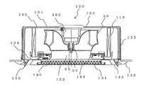
- FIG. 1 is a perspective view of an indoor unit 100 of an air conditioning apparatus according to Embodiment 1 of the present invention.
- FIG. 2 is a view for explaining the configuration of the indoor unit 100 of the air conditioning apparatus of FIG.
- an indoor unit 100 of a four-way cassette type air conditioning apparatus that has a ceiling-embedded type that can be embedded in a ceiling of a room and has outlets 132 in four directions will be described.
- the indoor unit 100 is connected to the outdoor unit by a refrigerant pipe, and forms a refrigerant circuit that circulates the refrigerant to perform refrigeration, air conditioning, and the like.
- the indoor unit 100 has a housing 120 configured of a top plate 121 and a side plate 122.
- the indoor unit 100 is installed by being embedded in the ceiling of the room with the top plate 121 facing upward.
- the housing 120 is open at the side facing the room (lower side).
- a motor 180 is attached to the top plate 121 on the inner side.
- the substantially square shaped decorative panel 130 is attached to the lower side in plan view, and faces the room.
- a grill 131 serving as a suction port of air (gas) into the indoor unit 100 and a filter 140 for removing air after passing through the grill 131 are provided.
- a central portion of the lower surface of the indoor unit 100 has a main body suction port 123 which rectifies and flows air into the main body.
- a main body outlet 124 that allows air to flow out of the main body.
- the grill 131, the main body suction port 123, the main body outlet 124, and the outlet 132 communicate with each other to form an air passage in the indoor unit 100.
- a turbo fan 20 Inside the body of the indoor unit 100, a turbo fan 20, a bell mouth 160, a motor 180, an indoor heat exchanger 110, and a heat insulator 190 are provided.
- the turbo fan 20 is an impeller used for a centrifugal fan on which the rotating shaft 50 of the motor 180 is attached.
- the rotation of the turbo fan 20 forms a flow of air for sending out the air drawn in via the grille 131 to the side (the left and right direction in FIG. 1).
- the turbo fan 20 will be described later.
- the bell mouth 160 forms a suction air path for the turbo fan 20 and rectifies it.
- the motor 180 is attached to the top plate 121 such that the central portion of the top plate 121 and the rotary shaft 50 are orthogonal to each other.
- the rotating shaft 50 is oriented in the vertical direction.
- the motor 180 may be attached in contact with the top plate 121, or may be attached with a slight gap.
- the turbo fan 20 fixed to the rotating shaft 50 rotates around the rotating shaft 50.
- the indoor heat exchanger 110 is installed downstream of the turbo fan 20 in the air flow so as to surround the turbo fan 20.
- the indoor heat exchanger 110 functions as an evaporator during the cooling operation, and functions as a condenser during the heating operation.
- An air outlet 132 is formed on each side of the decorative panel 130 along each side of the decorative panel 130.
- the indoor unit 100 of the present embodiment has four outlets 132.
- Each outlet 132 has an outlet vane 150 serving as a wind direction deflector for changing the wind direction.
- Position control is performed by rotationally moving each blowoff vane 150 about an axis by driving a motor (not shown).
- the heat insulating material 190 to be the heat insulating means is attached to the inner surface of the housing 120 by pasting or the like.
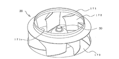
- FIG. 3 is a perspective view of a turbofan 20 according to Embodiment 1 of the present invention.
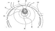
- FIG. 4 is an enlarged perspective view of a central portion of the turbofan 20 according to Embodiment 1 of the present invention.
- the turbo fan 20 rotates, it sucks in air from the direction of the rotating shaft 50 and blows out the sucked air in the outer circumferential direction crossing the rotating shaft 50.
- the turbo fan 20 according to the first embodiment is arranged such that the shroud 171 and the main plate 173 are opposed to each other.
- a plurality of (seven in FIG. 3) wings 172 are provided between the shroud 171 and the main plate 173.
- the shroud 171 has a bell mouth shape, and has an air suction port 171a at its central portion.
- the wings 172 form a flow of air from inside to outside of the turbo fan 20.
- the wing 172 of the present embodiment is a three-dimensional wing having a twisted shape between the shroud 171 and the main plate 173. With the wing 172 being a three-dimensional wing, noise reduction, power consumption reduction, and the like can be achieved.
- the main plate 173 is a base of the turbo fan 20, such as the wing 172 is joined.
- the main plate 173 has a central portion convex toward the inside of the turbo fan 20. Therefore, the central portion of the outer surface side of the main plate 173 is recessed, and the motor 180 is accommodated in the recessed space. Therefore, the main plate 173 covers the motor 180.
- FIG. 5 is a view for explaining the structure of the cross section of the turbofan 20 according to Embodiment 1 of the present invention.
- a boss 30 projecting from the surface is formed at the center of the convex portion 22 of the central portion of the main plate 173.
- the boss portion 30 has a sleeve 31 through which the rotating shaft 50 passes at the center, and has a cylindrical boss 32 on the outer peripheral side of the sleeve 31.
- a rubber cushion 33 intervenes between the outer peripheral surface of the sleeve 31 and the inner peripheral surface of the boss 32.
- the anti-vibration rubber 33 is bonded to the outer peripheral surface of the sleeve 31 and the inner peripheral surface of the boss 32.
- the outer peripheral surface of the boss 32 is covered with a material forming the main plate 173 of the turbo fan 20.
- the sleeve 31, the boss 32, and the anti-vibration rubber 33 are integrally formed with the main plate 173.
- the rotary shaft 50 is inserted through the sleeve 31 of the boss 30.
- the tip 51 of the rotating shaft 50 projects from the end face 34 of the boss 30.
- the distal end portion 51 is further inserted into the center hole 45 of the washer 40, and a fastening part 60 is further screwed into a portion projecting from the washer 40.
- the washer 40 is sandwiched between the end surface 34 of the boss 30 and the fastening component 60, and serves as a seat for the fastening component 60 and functions as a washer that prevents the fastening component 60 from loosening.
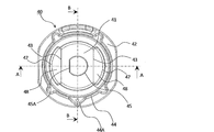
- FIG. 6 is a view of the washer 40 of FIG. 5 as viewed in the axial direction of the rotating shaft 50.
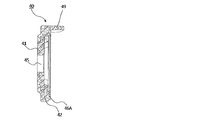
- FIG. 7 is a view showing a cross section AA of FIG.
- FIG. 8 is a cross-sectional view taken along the line BB in FIG.
- the washer 40 has a washer seating surface 41 at the center, and a washer outer periphery 42 so as to surround the washer seating surface 41.
- the washer seating surface portion 41 is a portion which is sandwiched between the fastening component 60 and the end surface 34 of the boss portion 30 and is in contact with the fastening component 60 and becomes a seating surface.
- the washer bearing surface portion 41 is made of, for example, a flat plate-like metal such as stainless steel which is press-formed.
- a central hole 45 is open at the central portion of the washer seat portion 41.
- the central hole 45 is formed with a D-cut portion 45A in which a part of a circular arc of a circle is cut by a straight line.
- the tip portion 51 is also formed in a shape obtained by cutting a part of a circle with a straight line, and when the tip portion 51 of the rotary shaft 50 penetrates the center hole 45, the tip portion 51 mate with the central hole 45; By being configured in this manner, the washer 40 does not rotate relative to the rotating shaft 50.
- the washer seating surface portion 41 two outer peripheral end faces 43 opposed to each other among the outer peripheral end faces of the flat material are exposed.
- the outer peripheral surface other than the outer peripheral end surface 43 is covered with a material forming the washer outer peripheral portion 42.
- the washer outer peripheral portion 42 is formed to surround the washer seating surface portion 41.
- the washer outer peripheral portion 42 includes an inner circumferential arc portion 47 facing the outer circumferential end surface 43.
- a portion surrounded by the outer circumferential end surface 43 and the inner circumferential arc portion 47 is an opening 48.
- the openings 48 are arranged symmetrically about the center of the washer 40.
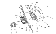
- FIG. 9 is a perspective view for describing the structure of the boss 30 of the turbo fan 20 according to Embodiment 1 of the present invention.
- the end face of the boss portion 30 of the turbo fan 20 is provided with two fitting portions 35 which project in symmetrical positions with respect to the center of the turbo fan 20.
- the fitting portions 35 face the respective fitting surfaces 35A with the central axis of the turbo fan 20 interposed therebetween.
- the washer 40 is configured to be inserted into the opening 48 of the washer 40 when the washer 40 is installed on the end face of the boss 30.
- the two outer peripheral end faces 43 of the washer seat portion 41 are in contact with the two fitting surfaces 35A of the fitting portion 35 so that the washer 40 and the boss 30 do not rotate relative to each other.
- the rotating shaft 50 and the washer 40 are fitted so as not to rotate relative to each other in the central hole 45 of the washer 40, and the washer 40 and the boss 30 do not rotate relative to each other by the outer peripheral end face 43 of the washer seating surface 41 and the fitting 35 It is fitted like that. That is, the three components of the rotating shaft 50, the washer 40, and the turbo fan 20 are engaged so as not to rotate relative to each other, and the rotational driving force of the motor 180 is transmitted from the rotating shaft 50 through the washer 40 to the turbo fan 20. It will be transmitted.
- the washer 40 is fixed in a state of being sandwiched between the washer 40 and the end face of the boss 30 by the fastening part 60 screwed to the tip 51 of the rotating shaft 50. Since the washer 40 can not be moved in the axial direction of the rotating shaft 50 by the fastening part 60, the fitted state of the outer peripheral end face 43 of the washer seat portion 41 and the fitting portion 35 is maintained.
- the washer 40 includes an axially extending projection 49 of the rotating shaft 50.
- the projecting portion 49 protrudes from the edge of the washer outer peripheral portion 42 and is configured not to interfere when the fastening component 60 is screwed to the distal end portion 51 of the rotating shaft 50. Further, only one protrusion 49 is provided on the washer outer peripheral portion 42 so that the direction of rotation of the washer 40 and the direction of the front and back can be determined.
- FIG. 10 is a view showing a state in which the washer 40 according to Embodiment 1 of the present invention is installed on the end face of the boss 30.
- the washer 40 When the washer 40 is disposed on the end face of the boss 30 in a normal state, the fitting portion 35 is inserted into the opening 48 of the washer 40.
- the protrusion 49 contacts the end surface 34 of the boss 30.
- the height H1 of the protrusion 49 from the washer seat portion 41 is higher than the height h of the fitting portion 35 from the end surface 34 of the boss 30. Therefore, when the washer 40 is assembled to the boss 30 opposite to the front and back, the opening 48 of the washer 40 and the fitting portion 35 do not fit.
- the total thickness H2 of the washer 40 that is, the height from the surface of the washer seating surface 41 on the boss 30 side to the projection 49 is the amount L of protrusion of the tip 30 of the rotating shaft 50 from the end face 34 of the boss 30 It is over.
- the washer 40 is advantageous in that it is easy for the operator to hold the turbo fan 20 when the turbo fan 20 is attached to the indoor unit 100 by providing the projection 49. Furthermore, since the outer shape of the washer 40 is larger than the outer shape of the fastening part 60, the worker can hold the washer 40 without inhibiting the operation of tightening the fastening part 60.
- the outer shape of the washer outer peripheral portion 42 is larger than the outer shape of the boss 32 of the boss portion 30. That is, when viewed from the axial direction of the rotating shaft 50, the boss 32 is concealed in the outer shape of the washer outer peripheral portion 42. Therefore, even when the boss 32 is made of metal, the boss 32 is not exposed to the surface that the user can contact, by the washer outer peripheral portion 42 made of the insulating material.
- the fastening part 60 is a nut part which is open at one end and which has a threaded portion inside the opening.
- the fastening component 60 is configured such that the exposed portion is made of an insulating material at least in a state of being fastened to the distal end portion 51 of the rotating shaft 50.
- the fastening part 60 is a part which covers the outer side of a metal nut with an insulating material and is integrally molded.
- the fastening part 60 is configured to be able to suppress loosening while improving safety.
- the washer outer peripheral portion 42 includes a rib 46 projecting in the axial direction of the rotating shaft 50.
- the rib 46 is provided on the entire circumference of the washer outer peripheral portion 42 and follows the outer shape of the washer outer peripheral portion 42. Further, the rib 46 is provided at a position not to interfere with the fastening component 60 in a state where the fastening component 60 is fastened to the distal end portion 51 of the rotary shaft 50.
- the rib 46 is provided so as to cover the gap generated between the fastening part 60 and the washer outer peripheral part 42, and desirably provided along the outer shape of the fastening part 60 as viewed from the axial direction of the rotating shaft 50 Good to have.
- the height of the rib 46 be larger than the gap between the fastening part 60 and the washer outer peripheral part 42.
- the fastening part 60 includes a gripping part 61 for gripping the fastening part 60 with a tool or the like for fastening the fastening part 60 to the boss 30.
- the grip portion 61 is formed on the tip end side in the axial direction of the rotating shaft 50 in the fastening component 60. Furthermore, the gripping portion 61 is formed to project in the axial direction of the rotating shaft 50 more than the projecting portion 49 of the washer 40. Therefore, since the grip portion 61 can be gripped by a tool or the like without being hindered by the projection 49, the tightening operation of the fastening component 60 becomes easy.
- a turbo having a motor 180, a rotating shaft 50 transmitting rotation of the motor 180, and a boss 30 into which the rotating shaft 50 is inserted at the center of rotation.
- the rotating shaft 50 is the fan 20, and the tip 51 protrudes from the boss 30, the tip 51 is inserted into the center hole 45 of the washer 40, the fastening part 60 is screwed, and the washer 40 is the fastening part 60 and the end face 34 of the boss 30 and provided with a washer seat 41 and a washer outer periphery 42 surrounding the outer periphery of the washer seat 41, the washer seat 41 and the washer outer periphery 42 Is integrally molded.
- the turbo fan 20 according to the first embodiment corresponds to the fan of the present invention.
- the indoor unit 100 of the ceiling-embedded air conditioner is described as an example, and the structure for attaching the boss portion 30 of the fan to the motor 180 is described.
- the present invention is applied to only the indoor unit 100 of the air conditioner. It is possible to apply to the apparatus etc. which have other fans, such as an outdoor unit.
- the turbo fan 20 can be attached to the rotating shaft 50 while holding the washer outer peripheral portion 42, so the efficiency of attaching and detaching the turbo fan 20 is improved.
- the washer bearing surface portion 41 includes the central hole 45 through which the distal end portion 51 of the rotating shaft 50 is inserted and the two outer peripheral end faces 43 opposed to each other. .
- the distal end portion 51 and the central hole 45 are fitted, and the boss portion 30 projects the fitting portion 35 on the side where the distal end portion 51 of the rotary shaft 50 protrudes, and the fitting portion 35 is an outer peripheral end face of the washer seating surface portion 41 Mates with 43.
- the washer bearing surface portion 41 includes the central hole 45 through which the distal end portion 51 of the rotating shaft 50 is inserted and the two outer peripheral end faces 43 opposed to each other. .
- the washer 40 has two openings 48 at symmetrical positions with respect to the central hole 45, and the opening 48 is formed by the outer peripheral end face 43 of the washer seat portion 41 and the inner peripheral surface of the washer outer peripheral portion 42.
- the washer outer peripheral portion 42 is connected to the washer seating surface portion 41 at the outer circumferential portion of the washer seating surface portion 41 excluding the outer circumferential end surface 43.
- the power of the motor 180 is not transmitted to the washer outer peripheral portion 42. Therefore, as described in the above (1) to (3), it is possible to transmit the rotational driving force of the rotating shaft 50 to the turbo fan 20 while improving the efficiency of attaching and detaching the turbo fan 20.
- the washer outer peripheral portion 42 has the protruding portion 49 protruding in the axial direction of the rotating shaft 50.
- the washer 40 has a structure that makes it easy to distinguish the front and back, and therefore, it is possible to suppress erroneous attachment at the time of attaching and detaching the turbo fan 20.
- the washer 40 is more easily held by the operator by providing the protrusion 49, the working efficiency is improved.
- the height of the protrusion 49 from the washer seat 41 is higher than the height from the end face of the boss 30 to the tip of the fitting 35.
- the fastening component 60 has the contact surface 62 in contact with the washer seat portion 41 and the gripping portion 61 gripped at the time of fastening.
- the grip portion 61 is formed to project in the axial direction of the rotary shaft 50 more than the protrusion 49.
- the washer outer peripheral portion 42 includes the rib 46 extending in the axial direction of the rotating shaft 50.
- the ribs 46 are provided all around the outer periphery of the washer outer peripheral portion 42.
- the boss 30 includes the sleeve 31 through which the rotary shaft 50 is inserted, the cylindrical boss 32 located outside the sleeve 31, and the outer periphery of the sleeve 31. And an anti-vibration rubber 33 interposed between the surface and the inner circumferential surface of the boss 32.
- the outer periphery of the washer outer peripheral portion 42 is larger than the end face of the boss 32.
- the washer bearing surface portion 41 is made of a flat metal, and the washer outer peripheral portion 42 is made of an insulating material. With such a configuration, the distance from the surface that can be touched by the operator or the user to the metal part such as the washer seat 41 can be secured, and the safety is improved.
- the indoor unit 100 of the air conditioning apparatus according to Embodiment 1 includes the turbofan 20 according to any one of (1) to (10). With this configuration, even when the turbo fan 20 is attached and detached toward the ceiling, for example, as in the indoor unit 100 of the ceiling-embedded air conditioner, the work efficiency is improved. The safety can be further improved.
Landscapes
- Engineering & Computer Science (AREA)
- General Engineering & Computer Science (AREA)
- Mechanical Engineering (AREA)
- Chemical & Material Sciences (AREA)
- Combustion & Propulsion (AREA)
- Structures Of Non-Positive Displacement Pumps (AREA)
- Bolts, Nuts, And Washers (AREA)
Abstract
Priority Applications (5)
| Application Number | Priority Date | Filing Date | Title |
|---|---|---|---|
| US16/617,694 US11118597B2 (en) | 2017-07-31 | 2017-07-31 | Fan and indoor unit of air-conditioning apparatus provided with fan |
| EP17885438.6A EP3462038B1 (fr) | 2017-07-31 | 2017-07-31 | Ventilateur et machine intérieure de dispositif de climatisation comportant un ventilateur |
| PCT/JP2017/027595 WO2019026097A1 (fr) | 2017-07-31 | 2017-07-31 | Ventilateur et machine intérieure de dispositif de climatisation comportant un ventilateur |
| CN201780093485.5A CN110998102B (zh) | 2017-07-31 | 2017-07-31 | 风扇和具备风扇的空调装置的室内机 |
| JP2019533727A JP6749495B2 (ja) | 2017-07-31 | 2017-07-31 | ファン及びファンを備えた空気調和装置の室内機 |
Applications Claiming Priority (1)
| Application Number | Priority Date | Filing Date | Title |
|---|---|---|---|
| PCT/JP2017/027595 WO2019026097A1 (fr) | 2017-07-31 | 2017-07-31 | Ventilateur et machine intérieure de dispositif de climatisation comportant un ventilateur |
Publications (1)
| Publication Number | Publication Date |
|---|---|
| WO2019026097A1 true WO2019026097A1 (fr) | 2019-02-07 |
Family
ID=65233567
Family Applications (1)
| Application Number | Title | Priority Date | Filing Date |
|---|---|---|---|
| PCT/JP2017/027595 Ceased WO2019026097A1 (fr) | 2017-07-31 | 2017-07-31 | Ventilateur et machine intérieure de dispositif de climatisation comportant un ventilateur |
Country Status (5)
| Country | Link |
|---|---|
| US (1) | US11118597B2 (fr) |
| EP (1) | EP3462038B1 (fr) |
| JP (1) | JP6749495B2 (fr) |
| CN (1) | CN110998102B (fr) |
| WO (1) | WO2019026097A1 (fr) |
Families Citing this family (6)
| Publication number | Priority date | Publication date | Assignee | Title |
|---|---|---|---|---|
| FR3077105B1 (fr) * | 2018-01-19 | 2020-02-14 | Safran Electrical & Power | Ventilateur pour un groupe de refroidissement d'aeronef |
| US10975879B2 (en) | 2018-07-18 | 2021-04-13 | The Charles Machine Works, Inc. | Centrifugal fan |
| US11702806B2 (en) * | 2020-09-14 | 2023-07-18 | Curbtender Sweepers Llc | Fan for regenerative air vacuum street sweeper, and method of fan manufacture and assembly |
| JP7818933B2 (ja) * | 2021-11-18 | 2026-02-24 | 三菱重工サーマルシステムズ株式会社 | 空調装置 |
| CN114736797A (zh) * | 2022-03-30 | 2022-07-12 | 昆明柏特生物科技有限公司 | 一种细胞培养反应器 |
| US12246183B1 (en) * | 2023-10-06 | 2025-03-11 | Greatbatch Ltd. | Self-centering polymeric washer that prevents misalignment when positioned between a feedthrough and a circuit board supporting EMI filter capacitors for a medical device |
Citations (6)
| Publication number | Priority date | Publication date | Assignee | Title |
|---|---|---|---|---|
| JPS615399U (ja) * | 1984-06-18 | 1986-01-13 | 東洋ラジエ−タ−株式会社 | フアンの取付装置 |
| JPH07103193A (ja) * | 1993-09-30 | 1995-04-18 | Toshiba Corp | 送風ファン |
| JPH1162891A (ja) | 1997-08-08 | 1999-03-05 | Mitsubishi Heavy Ind Ltd | ターボフアン及びこれを備える空気調和機 |
| JP2008101533A (ja) * | 2006-10-19 | 2008-05-01 | Fujitsu General Ltd | 送風ファンの取付構造 |
| JP2009057918A (ja) * | 2007-08-31 | 2009-03-19 | Max Co Ltd | 送風装置 |
| JP2010101288A (ja) * | 2008-10-27 | 2010-05-06 | Mitsubishi Electric Corp | 送風機 |
Family Cites Families (14)
| Publication number | Priority date | Publication date | Assignee | Title |
|---|---|---|---|---|
| US4026183A (en) * | 1976-05-17 | 1977-05-31 | Illinois Tool Works Inc. | Sealing washer |
| KR830002159A (ko) * | 1979-03-21 | 1983-05-23 | 에이. 더블유. 프리쉬 | 고속 가스 압축기용 임펠러와 축 조립체 |
| JPS62297522A (ja) | 1987-05-30 | 1987-12-24 | 東芝テック株式会社 | 器具取付け装置 |
| JPH05231386A (ja) * | 1992-02-17 | 1993-09-07 | Mitsubishi Electric Corp | 羽根回り止めワッシャ |
| US6190134B1 (en) * | 1999-09-28 | 2001-02-20 | Molded Products Company | Fan blade stabilization apparatus |
| JP2002276594A (ja) | 2001-03-15 | 2002-09-25 | Sanko Gosei Ltd | プロペラファン |
| JP2003161293A (ja) * | 2001-11-22 | 2003-06-06 | Mitsubishi Electric Corp | ファンモータの防振装置 |
| ITMI20020097U1 (it) * | 2002-02-26 | 2003-08-26 | Faber Spa | Ventilatore con motore a rotore interno con dispositivo di fissaggio rapido di una girante |
| GB0224721D0 (en) * | 2002-10-24 | 2002-12-04 | Holset Engineering Co | Compressor wheel assembly |
| FR2891027B1 (fr) * | 2005-09-22 | 2008-01-11 | Aereco Sa | Turbine amovible pour ventilateur |
| CN101382164A (zh) * | 2007-09-07 | 2009-03-11 | 苏州三星电子有限公司 | 离心风叶固定用垫片 |
| CN102939701B (zh) * | 2010-06-14 | 2015-05-06 | 松下电器产业株式会社 | 风扇马达、使用了该风扇马达的车载用空调装置以及风扇马达的组装方法 |
| CN201916245U (zh) * | 2010-12-28 | 2011-08-03 | 中山大洋电机股份有限公司 | 一种鼓风机风轮的防转结构 |
| CN104343718A (zh) * | 2013-08-08 | 2015-02-11 | 威海克莱特菲尔风机股份有限公司 | 紧固件防松装置 |
-
2017
- 2017-07-31 WO PCT/JP2017/027595 patent/WO2019026097A1/fr not_active Ceased
- 2017-07-31 CN CN201780093485.5A patent/CN110998102B/zh not_active Expired - Fee Related
- 2017-07-31 JP JP2019533727A patent/JP6749495B2/ja not_active Expired - Fee Related
- 2017-07-31 EP EP17885438.6A patent/EP3462038B1/fr active Active
- 2017-07-31 US US16/617,694 patent/US11118597B2/en not_active Expired - Fee Related
Patent Citations (6)
| Publication number | Priority date | Publication date | Assignee | Title |
|---|---|---|---|---|
| JPS615399U (ja) * | 1984-06-18 | 1986-01-13 | 東洋ラジエ−タ−株式会社 | フアンの取付装置 |
| JPH07103193A (ja) * | 1993-09-30 | 1995-04-18 | Toshiba Corp | 送風ファン |
| JPH1162891A (ja) | 1997-08-08 | 1999-03-05 | Mitsubishi Heavy Ind Ltd | ターボフアン及びこれを備える空気調和機 |
| JP2008101533A (ja) * | 2006-10-19 | 2008-05-01 | Fujitsu General Ltd | 送風ファンの取付構造 |
| JP2009057918A (ja) * | 2007-08-31 | 2009-03-19 | Max Co Ltd | 送風装置 |
| JP2010101288A (ja) * | 2008-10-27 | 2010-05-06 | Mitsubishi Electric Corp | 送風機 |
Also Published As
| Publication number | Publication date |
|---|---|
| EP3462038B1 (fr) | 2020-07-08 |
| US11118597B2 (en) | 2021-09-14 |
| EP3462038A4 (fr) | 2019-10-09 |
| CN110998102B (zh) | 2021-04-02 |
| JPWO2019026097A1 (ja) | 2020-02-27 |
| JP6749495B2 (ja) | 2020-09-02 |
| US20200116157A1 (en) | 2020-04-16 |
| CN110998102A (zh) | 2020-04-10 |
| EP3462038A1 (fr) | 2019-04-03 |
Similar Documents
| Publication | Publication Date | Title |
|---|---|---|
| JP6749495B2 (ja) | ファン及びファンを備えた空気調和装置の室内機 | |
| EP3348840B1 (fr) | Structure d'ensemble ventilateur à volute et climatiseur posé sur le sol | |
| EP3348841B1 (fr) | Structure d'ensemble ventilateur à volute et climatiseur posé sur le sol | |
| WO2005052377A1 (fr) | Roue a aubes pour soufflante centrifuge et soufflante centrifuge equipee d'une telle roue | |
| AU2013310396B2 (en) | Centrifugal fan and air-conditioning apparatus including the same | |
| JP2017116188A (ja) | 空気調和機の室内機 | |
| US20080134713A1 (en) | Turbo fan and air conditioner having the same | |
| WO2016071948A1 (fr) | Ventilateur hélicoïde, dispositif de ventilateur hélicoïde, et unité extérieure pour dispositif de conditionnement d'air | |
| JP6532658B2 (ja) | 室内機ユニット及び空気調和機 | |
| JP5949752B2 (ja) | 空気調和機 | |
| CN205089654U (zh) | 一种蜗壳风机组合结构及立式空调器 | |
| CN205047468U (zh) | 一种蜗壳风机组合结构及立式空调器 | |
| WO2016170652A1 (fr) | Unité intérieure et dispositif de climatisation | |
| US10428835B2 (en) | Fan and air-conditioning apparatus | |
| EP3098453B1 (fr) | Ventilateur et dispositif de climatisation | |
| JP3846468B2 (ja) | ターボファン | |
| JP2014227865A (ja) | 送風機の支持構造 | |
| JP7749621B2 (ja) | 送風装置 | |
| CN2455952Y (zh) | 离心风机 | |
| JP2009210191A (ja) | 換気扇 | |
| JP2007009754A (ja) | ファン、電動送風機および電気掃除機 | |
| JP2010038016A (ja) | プロペラファンの整流治具及び空気調和装置の室外ユニット | |
| JP3153183U (ja) | 遠心送風機 | |
| JP2008031902A (ja) | 電動送風機 | |
| JP2019178657A (ja) | 送風装置および送風装置の製造方法 |
Legal Events
| Date | Code | Title | Description |
|---|---|---|---|
| WWE | Wipo information: entry into national phase |
Ref document number: 2017885438 Country of ref document: EP |
|
| ENP | Entry into the national phase |
Ref document number: 2017885438 Country of ref document: EP Effective date: 20180704 |
|
| 121 | Ep: the epo has been informed by wipo that ep was designated in this application |
Ref document number: 17885438 Country of ref document: EP Kind code of ref document: A1 |
|
| ENP | Entry into the national phase |
Ref document number: 2019533727 Country of ref document: JP Kind code of ref document: A |
|
| NENP | Non-entry into the national phase |
Ref country code: DE |