WO2019026548A1 - 水生生物の飛び出し防止装置 - Google Patents
水生生物の飛び出し防止装置 Download PDFInfo
- Publication number
- WO2019026548A1 WO2019026548A1 PCT/JP2018/025768 JP2018025768W WO2019026548A1 WO 2019026548 A1 WO2019026548 A1 WO 2019026548A1 JP 2018025768 W JP2018025768 W JP 2018025768W WO 2019026548 A1 WO2019026548 A1 WO 2019026548A1
- Authority
- WO
- WIPO (PCT)
- Prior art keywords
- electrode
- water
- water tank
- aquatic organisms
- floating
- Prior art date
- Legal status (The legal status is an assumption and is not a legal conclusion. Google has not performed a legal analysis and makes no representation as to the accuracy of the status listed.)
- Ceased
Links
Images


Classifications
-
- A—HUMAN NECESSITIES
- A01—AGRICULTURE; FORESTRY; ANIMAL HUSBANDRY; HUNTING; TRAPPING; FISHING
- A01K—ANIMAL HUSBANDRY; AVICULTURE; APICULTURE; PISCICULTURE; FISHING; REARING OR BREEDING ANIMALS, NOT OTHERWISE PROVIDED FOR; NEW BREEDS OF ANIMALS
- A01K63/00—Receptacles for live fish, e.g. aquaria; Terraria
- A01K63/003—Aquaria; Terraria
- A01K63/006—Accessories for aquaria or terraria
-
- A—HUMAN NECESSITIES
- A01—AGRICULTURE; FORESTRY; ANIMAL HUSBANDRY; HUNTING; TRAPPING; FISHING
- A01K—ANIMAL HUSBANDRY; AVICULTURE; APICULTURE; PISCICULTURE; FISHING; REARING OR BREEDING ANIMALS, NOT OTHERWISE PROVIDED FOR; NEW BREEDS OF ANIMALS
- A01K61/00—Culture of aquatic animals
- A01K61/60—Floating cultivation devices, e.g. rafts or floating fish-farms
-
- A—HUMAN NECESSITIES
- A01—AGRICULTURE; FORESTRY; ANIMAL HUSBANDRY; HUNTING; TRAPPING; FISHING
- A01K—ANIMAL HUSBANDRY; AVICULTURE; APICULTURE; PISCICULTURE; FISHING; REARING OR BREEDING ANIMALS, NOT OTHERWISE PROVIDED FOR; NEW BREEDS OF ANIMALS
- A01K63/00—Receptacles for live fish, e.g. aquaria; Terraria
-
- A—HUMAN NECESSITIES
- A01—AGRICULTURE; FORESTRY; ANIMAL HUSBANDRY; HUNTING; TRAPPING; FISHING
- A01M—CATCHING, TRAPPING OR SCARING OF ANIMALS; APPARATUS FOR THE DESTRUCTION OF NOXIOUS ANIMALS OR NOXIOUS PLANTS
- A01M29/00—Scaring or repelling devices, e.g. bird-scaring apparatus
- A01M29/24—Scaring or repelling devices, e.g. bird-scaring apparatus using electric or magnetic effects, e.g. electric shocks, magnetic fields or microwaves
-
- Y—GENERAL TAGGING OF NEW TECHNOLOGICAL DEVELOPMENTS; GENERAL TAGGING OF CROSS-SECTIONAL TECHNOLOGIES SPANNING OVER SEVERAL SECTIONS OF THE IPC; TECHNICAL SUBJECTS COVERED BY FORMER USPC CROSS-REFERENCE ART COLLECTIONS [XRACs] AND DIGESTS
- Y02—TECHNOLOGIES OR APPLICATIONS FOR MITIGATION OR ADAPTATION AGAINST CLIMATE CHANGE
- Y02A—TECHNOLOGIES FOR ADAPTATION TO CLIMATE CHANGE
- Y02A40/00—Adaptation technologies in agriculture, forestry, livestock or agroalimentary production
- Y02A40/80—Adaptation technologies in agriculture, forestry, livestock or agroalimentary production in fisheries management
- Y02A40/81—Aquaculture, e.g. of fish
Definitions
- the present invention relates to an apparatus for preventing jumping out of aquatic organisms.
- the lid provided on the water tank can prevent the aquatic organisms from jumping out of the water tank by covering the top of the water tank.
- the lid may be lifted by the force of collision of the aquatic organism on the lid, and it may be difficult to prevent jumping out of the water tank.
- An apparatus for preventing jumping out of aquatic organisms is electrically connected to an electrode unit installed on the inner periphery of a water tank for breeding aquatic organisms, and the electrode unit, and an electric pulse is applied to the electrode unit.
- a power supply unit for applying a water source wherein the electrode unit extends horizontally over a part or all of the inner periphery of the water tank, And an electric pulse is applied to the electrode portion.
- the stimulation resulting from the electric pulse is given to the aquatic organism so as not to bring the aquatic organism close to the water surface, without directly touching the aquatic organism. Out of the water tank can be prevented.
- FIG. 1st Embodiment It is a perspective view which shows typically the jumping-out prevention apparatus of the aquatic organism in 1st Embodiment. It is a longitudinal cross-sectional view of the jumping-out prevention apparatus of the aquatic organism of FIG. It is a figure which shows an example of the electric pulse applied to an electrode part from the power supply part in 1st Embodiment. It is a perspective view which shows typically the modification of the jumping out prevention apparatus of the aquatic organism in 1st Embodiment. It is a figure which shows an example of the electric pulse applied to an electrode part from a power supply part in the modification of FIG. It is a perspective view which shows typically the jumping-out prevention apparatus of the aquatic organism in 2nd Embodiment.
- aquatic organisms include all organisms that live in water, and in particular include organisms that live while moving in water.
- aquatic organisms include fish, mammals such as whales and dolphins which inhabit mainly in water, aquatic insects such as sea turtles and sea lions, creatures such as jellyfish, squid, octopus, shrimp, saw crab, crayfish and the like.
- Fishes include freshwater fish like Hatchet, African Lamp Eye, Prati, Snakehead, Arowana, saltwater fish like tuna, and brackishwater fish like Suzuki and Bora.
- water contained in the surrounding area together with aquatic organisms includes freshwater, brackish water, and seawater.
- Seawater also includes artificial seawater artificially prepared to simulate the composition of natural seawater. Also, it may include water whose water quality has been adjusted as needed, or a liquid or fluid similar to water, which has been adjusted so that aquatic organisms can be inhabited.
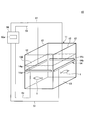
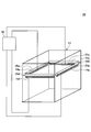
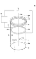
- FIG. 1 is a perspective view showing an outline of the pop-out prevention device in the present embodiment.
- FIG. 2 is a longitudinal sectional view of the pop-out prevention device of FIG.
- the vertical and horizontal sizes may differ from the actual scale, and the scale for each member may also differ from the actual.
- the pop-out prevention device 10 is provided in the water tank 11 in which the aquatic life is stored, and is disposed inside the water tank 11 below the water surface (especially in the vicinity of the water surface) And a power supply unit 50 electrically connected to the electrode unit 14 and applying an electric pulse.
- the water tank 11 has a bottom portion 13 and a cylindrical side wall portion 12 extending upward from the bottom portion 13 and is formed in a bottomed cylindrical shape.
- water is also accommodated in the water tank 11, and a water surface 100 is formed.
- the bottom 13 and the side wall 12 are formed of a watertight wall-like member.
- the bottom portion 13 and the side wall portion 12 are formed of a plate material
- the bottom portion 13 has a substantially square shape
- the square side wall portion 12 is extended from each side of the square.
- the bottom 13 and the side wall 12 and the side walls 12 are connected so as not to allow water to pass through.
- the upper end of the water tank 11 is open, and the lower end is closed by the bottom 13. Therefore, even if the water tank 11 is filled with water, the water in the water tank 11 does not leak. Therefore, as shown in FIG. 1, the water tank 11 can accommodate water together with the aquatic organisms 1 that live in the water.
- Such a water tank 11 is mainly used on land.
- the bottom part 13 and the side wall part 12 show embodiment which consists of plate-shaped members, the water tank 11 may be embedded at the ground, for example.
- a water tank is known in which a recess is formed on a foundation made of ground, concrete or the like and paved with concrete or the like to form a bottom and a side wall.
- the pop-out prevention device of the present invention is applicable even to such a relatively large water tank.
- the material which comprises the bottom part 13 and the side wall part 12 has a preferable insulating material like glass, resin, and concrete, for example.
- a preferable insulating material like glass, resin, and concrete, for example.
- the electrode portion 14 has at least two electrode members electrically separated from each other, and each electrode portion is provided on the inner periphery or the inner side of the side wall portion 12 of the water tank 11.
- each electrode portion is provided on the inner periphery or the inner side of the side wall portion 12 of the water tank 11.
- the electrode members 14a, 14b, 14c, 14d is provided on the surface in contact with the electrode.
- the electrode members 14a, 14b, 14c and 14d are at least electrically separated from one another.
- Each of the electrode members 14a, 14b, 14c and 14d is arranged above the half of the height of the side wall portion 12 or at a position corresponding to a predetermined water depth area when water is poured into the water tank 11.
- the electrode portion 14 When water is in the water tank 11, the electrode portion 14 is above the half of the water depth, and a predetermined water depth region below the water surface 100, in the present embodiment, in the vicinity of the water surface 100, against the water surface 100. And arranged substantially parallel.
- each electrode member 14a, 14b, 14c, 14d is formed in a straight line, and has a length corresponding to the width in the lateral direction (horizontal direction) of the attached side wall portion Or slightly shorter than the width of the side wall.
- FIG. 1 shows an example in which the electrode members 14a and 14b are attached to the opposing side walls 12, and the electrode members 14c and 14d are attached to the opposing side walls 12.
- the water surface 100 is about two thirds the height (or depth) of the entire height (or depth) of the water tank 11, and the electrode portion 14 is the water surface in the depth from the bottom 13 to the water surface 100. It is provided in the position of about a quarter depth from.
- the electrode portion 14 is located at a position corresponding to a predetermined water depth region (a region above the half of the height of the sidewall 12) on the inner surface of the sidewall 12, for example, a position corresponding to the vicinity of the water surface 100.
- the present embodiment extends horizontally in a part or the whole of the inner circumference of the water tank 11 so as to surround the entire inner circumference of the water tank 11 with the entire electrode portion 14 in the present embodiment.
- the outside of the electrode portion 14 can be directly fixed to the inner surface of the side wall portion 12.
- the electrode unit 14 is fixed to the water tank 11 by an adhesive (not shown).
- the electrode portion 14 is provided to be in contact with the water contained in the water tank 11, and is provided at a height above half of the height of the side wall portion 12 of the water tank 11. More specifically, it is provided at a height above half of the water level when the water is put into the water tank 11.
- the electrode portion 14 can be extended substantially parallel to the surface 100. However, they may be arranged to be inclined with respect to the water surface 100 or different in the position in the depth direction in a step-like manner.
- a part or all of the surface of the electrode portion 14 has conductivity. Then, in a state where the electrode portion 14 is disposed under the water surface 100, that is, in the water, the conductive surface is configured to be in contact with water. Moreover, it is preferable that the surface of the electrode part 14 further has corrosion resistance.
- Various conductive materials can be applied as a material of which the electrode portion 14 is made.
- metallic materials such as stainless steel, platinum, iridium, ruthenium, rhodium, titanium, copper, chromium and / or alloys containing these
- Nonmetallic materials such as carbon, conductive polymers comprising polyacetylene, polypyrrole, polythiophene, polyaniline, etc., and composites obtained by adding inorganic and / or organic (for example, carbon etc.) conductive materials to these polymer materials Materials etc. can also be applied.
- the shape of the electrode portion 14 is not particularly limited.
- the shape of the electrode portion 14 may be a band as shown in FIG. 1 or a line.
- the electrode part 14 may be mesh shape. It may be a braided wire or a stranded wire made of a plurality of linear materials made of the above-described conductive material or the like.
- the size of the cross section perpendicular to the extending direction of the electrode portion 14 is not particularly limited.
- the size of the cross section of the electrode unit 14 may be set according to the material of which the electrode unit 14 is made.
- the width of the electrode portion 14 is 0.20 mm or more and 0.60 mm or less, and when the electrode portion 14 is made of carbon, the width of the electrode portion 14 is 0.. It is preferable that they are 02 mm or more and 0.06 mm or less. If the size of the electrode portion 14 is within the above range, visual inspection of the electrode portion 14 is not easy, so the interior property of the pop-out prevention device 10 is improved.
- the surface of the side wall portion 12 can be coated with a transparent conductive material made of, for example, ITO, IZO, AZO, GZO, ATO or the like to form the electrode portion 14.
- the coating may be applied only at predetermined positions in a stripe or band shape, or may be applied entirely from the upper half of the sidewall 12 or the water surface to a height corresponding to a predetermined water depth area.
- the electrode unit 14 is electrically connected to the power supply unit 50 via the wiring unit 51 and a connector (not shown) and / or an electrical contact, etc. so that an electric pulse can be applied to the electrode unit 14 It is done. More specifically, as shown in FIG. 1, the electrode members 14 a, 14 b, 14 c and 14 d are electrically connected to the power supply unit 50 through the wiring unit 51. For example, the power supply unit 50 can selectively apply an electric pulse as described below to each of the storage battery and / or the power supply unit from the outside and each of the electrode members 14a, 14b, 14c, and 14d. And the control unit 50a configured in FIG. In the example shown in FIG. 1, the control unit 50a is built in the power supply unit 50. However, the control unit 50a is provided outside the power supply unit 50, and can communicate with the power supply unit 50 by wire or radio. It may be connected.
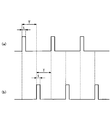
- FIG. 3 illustrates an electrical pulse applied to the electrode means.
- FIG. 3 (a) shows an example of a square wave
- FIGS. 3 (b) and 3 (c) show an example of a sine wave.
- FIG.3 (c) has shown the example to which the sine wave to which wave height value A becomes small gradually is applied in period t.
- the maximum crest value is shown as a representative value of the crest value A.
- the peak value A may change within the period t.
- the peak value A may be negative.
- high frequency electrical pulses may be applied during the period t. That is, the electric pulse of FIG. 3A may be one to which a high frequency electric pulse is intermittently applied.
- the repetition frequency of the intermittently applied high frequency electric pulse is the period T, and the frequency of the high frequency applied in one electric pulse may be referred to as a frequency.
- the voltage / current value in the period in which the electric pulse is not applied in the period T may be 0, DC, or AC. Bias voltage / current may be applied. Also, it is conceivable that weak, direct current or alternating current / voltage components may be superimposed.
- such an electric pulse can be selectively applied to the electrode members 14a, 14b, 14c and 14d.
- the control unit 50a of the power supply unit 50 applies an electric pulse as described above to the adjacent electrode member among the electrode members 14a, 14b, 14c, and 14d (+ side), and an electrode member to which the electric pulse is applied.
- the electrode member disposed opposite to the electrode can be set to the ground side ( ⁇ side).
- an electric pulse may be applied to the opposing electrode member (+ side), and the electrode member adjacent to the electrode member may be grounded ( ⁇ side).
- the electrode members can be selected so that the electrode member which is on the + side and the electrode member which is on the ⁇ side are interchanged every period T.
- an electric pulse may be applied only to one or more of the plurality of electrode members 14a, 14b, 14c and 14d, and the other electrode members may be grounded.
- one or more electrode members can be sequentially selected from the plurality of electrode members 14a, 14b, 14c, and 14d to apply an electric pulse.
- an electric field is formed around the electrode member to which the electric pulse is applied, so that the electrode member to which the electric pulse is applied at a sufficiently high speed to the movement of aquatic organisms is replaced. Good.
- an electric pulse can be applied to the electrode member such that an electric field giving an electric stimulus to which the aquatic organism 1 dislikes is generated to generate a region where the aquatic organism 1 does not lean around the electrode portion 14.
- the aquatic organism 1 When the aquatic organism 1 moves from the bottom 13 side toward the water surface 100 and enters the electric field region e, it receives electrical stimulation. Such stimulation increases as the distance to the electrode portion 14 decreases, so the aquatic organism 1 moving from the bottom 13 side returns to the bottom 13 side without traversing the electric field region e. Run away from the area. Therefore, the aquatic organism 1 can be prevented from jumping over the side wall portion 12 from the water surface 100 inside the water tank 11, that is, jumping out of the water tank 11.
- that the aquatic organism 1 traverses the electric field region means that the aquatic organism 1 enters the electric field region from the bottom 13 side and exits from the water surface 100 side.
- the aquatic organism 1 can be prevented from jumping out of the water tank 11 without contacting the aquatic organism 1. Therefore, it is possible to suppress the death of the aquatic organism 1 due to the falling from the water tank 11 caused by the jumping out of the aquatic organism 1 and to suppress the decrease in the number of the aquatic organisms 1 accommodated in the water tank 11.
- the pop-out prevention device in the present embodiment forms an electric field area in a desired area in the water tank 11 by the electrode unit 14 provided inside the water tank 11.
- the aquatic organism 1 enters the electric field region from the bottom 13 side, the aquatic organism 1 leaves the electric field region so as to return to the bottom 13 side without traversing the electric field region. Therefore, jumping out of the aquatic organism 1 from the inside of the water tank 11 to the outside can be prevented.
- predetermined water depth area means the height above the height of the water tank, more specifically the side wall (or the surrounding part described later), that is, half the length of the water tank (or the surrounding part) in the water depth direction Side) refers to the height range (position). If the electrode portion 14 is disposed at this height / position, the electrode portion 14 is always disposed above the half of the water depth when water is contained in the water tank 11 (or in the enclosure portion) up to the height of the electrode portion 14 It will be done.
- the pop-out prevention device 10 can prevent the pop-out of the aquatic organism 1, there may be a region where no electric field is formed, such as around the central portion M of the water surface 100 in the water tank 11, for example. This is because it is sufficient for the electric field region to be formed in a region where it is difficult for the aquatic organism 1 to fly out from the inside of the water tank 11 to the outside of the water tank 11. In the vicinity of the central portion M of the water surface 100 in the water tank 11, even if the aquatic organism 1 jumps out of the water surface 100 in the water tank 11 through the region where the electric field is not formed, the aquatic organism 1 crosses the sidewall 12 and the water tank Jumping out of 11 is difficult.
- the intensity of the stimulus given to the aquatic organism due to the electric pulse or the intensity of the stimulus felt by the aquatic organism depends on the intensity such as the peak value or the average value of the electrical pulse, but the other It also depends strongly on the parameters of. That is, the sensitivity of aquatic organisms to stimulation is not only intensity-dependent but also frequency-dependent. Therefore, various parameters such as the intensity, frequency, period, and duty ratio of the applied electric pulse may be adjusted in order to obtain a stimulus of strength that can exert a desired influence on aquatic organisms. Moreover, the dependency differs depending on the size, type, etc. of the aquatic organism.
- an electric pulse of relatively low intensity has sufficient strength. It can give a stimulus. If the intensity of the electrical pulse, such as the voltage value or the current value, can be reduced, the power consumption of the entire system can be reduced. In addition, undesired effects on aquatic organisms that should be prevented from jumping out, such as effects such as shock due to excessive strength of voltage / current and damage to skin, muscles, internal organs, etc., can be minimized. Moreover, the influence by the electrical corrosion etc. to an electrode can also be reduced. That is, by selecting an optimal parameter for an aquatic organism to be prevented from popping out, such as an optimal frequency, a sufficiently strong electric field can be used to provide sufficient stimulation to prevent the aquatic organism from popping out. It will be possible.
- More specific parameters of the electric pulse applied to the electrode portion 14 are not particularly limited as long as an electric field can be formed in a desired region in water.
- the parameters of the electric pulse applied to the electrode unit 14 are determined depending on the shape of the water tank, the size of the water tank, the type of aquatic organism, the size of the aquatic organism, the water quality, and the like.
- the voltage of the electrical pulse applied to the electrode unit 14 can be 9V or more and 16V or less.
- the frequency of the electric pulse is preferably 0.1 kHz or more and 10.0 kHz or less, more preferably 0.1 kHz or more and 5.0 kHz or less, and further preferably 0.5 kHz or more and 1.5 kHz or less preferable.
- the frequency of the electrical pulse can be applied to be different from time to time within a predetermined frequency range.
- a frequency range for example, a range of 0.1 to 2.0 kHz, 0.5 to 1.5 kHz, 0.8 to 1.1 kHz, 0.5 to 1.0 kHz or the like can be applied.
- the frequency may be swept in this frequency range so as to periodically change according to time, or may be randomly selected from this frequency range.
- an electric pulse is applied to the electrode unit 14 by changing the frequency in this manner, it is possible to prevent the pop-out regardless of the type and size of the aquatic organism.
- the electric pulse can be applied to the electrode unit 14 while changing each parameter such as the voltage and duty ratio of the electric pulse.
- the electrode unit 14 is preferably provided at a water depth of 3 cm or more and 5 cm or less. In an environment where waves are easily generated, the electrode unit 14 is It is preferable that the electrode portion 14 be disposed at a depth deeper than the height of the water, and it is preferable that the electrode portion 14 be disposed so as not to go above the water surface. The jumping out of the aquatic organism 1 can be suppressed more reliably.
- the number of installed power supply units 50 is not particularly limited, and one power supply unit may be installed for a plurality of electrode members as shown in FIG. 1 or more than one for each of a plurality of electrode members.
- the shape of the cross section perpendicular to the depth direction of the water tank 11 may be a square as shown in FIG. 1, a rectangle, a circle, an ellipse or the like.
- the installation configuration of the electrode unit 14 is appropriately set.
- the electrode part 14 has electrode member 14a, 14b, 14c, 14d
- the installation structure of the electrode part 14 will be limited especially. It is not a thing. Any two or three of the electrode members 14a, 14b, 14c, 14d may be combined and electrically and / or structurally coupled to be integrally configured. Also, for example, each of the electrode members 14a, 14b, 14c and 14d may be divided into two or more. Dividing the electrode member into a large number in this way has an advantage that it is possible to individually adjust the on / off and parameters of the electric pulse at each portion of the inner circumference in the water tank 11.
- a plurality of electrode members can also be formed structurally connected (while being electrically separated). According to such a configuration, there is an advantage that the work of attaching the electrode member is simplified. Furthermore, although the electrode members 14a, 14b, 14c, and 14d have the same shape in the above embodiment, electrode devices having different shapes may be combined.
- FIG. 4 is a perspective view schematically showing a modified example of the pop-out prevention device in the present embodiment.
- the pop-out prevention device 10 a has an electrode portion 114 instead of the electrode portion 14 of the pop-out prevention device 10 of FIG. 1.
- the electrode unit 114 has a first electrode member 114a and a second electrode member 114b.
- Each of the first electrode member 114 a and the second electrode member 114 b shown in FIG. 4 has a substantially annular shape in which a part is opened, and the inner peripheral surface of the water tank 11 is substantially parallel to the water surface 100. Is located in The electrode members 114a and 114b are at least partially electrically disconnected.
- the electrode members 114 a and 114 b have a shape which is also structurally divided, but may be formed into an annular shape which is electrically cut only and structurally closed.
- the second electrode member 114 b is disposed below the first electrode member 114 a.
- the first electrode member 114a and the second electrode member 114b are provided at predetermined intervals in the depth direction, and are at least electrically separated from each other.
- the first electrode member 114a and the second electrode member 114b may be formed on the surface of a closed ring-shaped insulating single base material, and the electrode portion 114 may be integrally configured. .
- FIG. 3A An example of the electric pulse applied to the electrode members 114a and 114b via the power supply unit 50 is shown in FIG.
- the power supply unit 50 can apply electrical pulses as shown in FIG. 3A to the electrode members 114a and 114b at mutually different timings. That is, the electric pulse shown in FIG. 5A can be applied to the first electrode member 114a, and the electric pulse shown in FIG. 5B can be applied to the second electrode member 114b. In this way, in the first cycle T, when the first electrode member 114a is in the high state (+ side), the second electrode member 114b is in the low state (-side), and in the next cycle T, It is reversed.
- control unit 50a can select a desired electrode member from among the plurality of electrode members and apply an electric pulse. At this time, the control unit 50a selects an electrode member to which the electric pulse is applied according to the water surface 100 and / or the position of the aquatic organism 1, the water quality, the shape of the water tank 11, and / or the user's designation. can do.
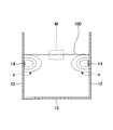
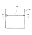
- FIG. 6 is a perspective view showing the pop-out prevention device in the present embodiment.
- 7 is a longitudinal sectional view of the pop-out prevention device of FIG.
- the electrode portion 14 is not directly attached to the water tank 11 as shown in FIGS. 1 and 2, but the electrode portion 14 is disposed in the water tank 11 via the floating portion 25.
- the second embodiment differs from the pop-out prevention device 10 of the first embodiment in that
- the pop-out prevention device 20 has a water tank 11, an electrode unit 14, a power supply unit 50, and a floating unit 25 provided inside the water tank 11.
- the floating portion 25 can float on the water surface 100 and is disposed on the inner surface of the water tank 11.
- the floating part 25 is comprised, for example from the member which can float in water like a foaming polystyrene, a balloon, etc.
- the floating portion 25 floats on the water surface 100 and holds the electrode portion 14 below the water surface below.
- the floating portion 25 is disposed in the vicinity of the inner surface of the first side wall member 12a and has a prismatic first floating member 25a for holding the first electrode member 14a, and the second side wall member 12b.
- the second floating member 25b which holds the second electrode member 14b and is arranged near the inner surface of the third side wall member 12c and holds the third electrode member 14c.
- a third floating member 25c, and a prismatic fourth floating member 25d disposed in the vicinity of the inner surface of the fourth side wall member 12d and holding the fourth electrode member 14d are provided. Then, the floating portion 25 maintains the underwater posture of the electrode portion 14 while floating on the water surface 100. For example, the floating portion 25 extends parallel to the water surface 100.
- Each floating portion 25 can be provided with the following configuration so as to be disposed at a predetermined position with respect to the side wall portion 12, that is, not flowed toward the center of the water tank 11.
- the outside of the floating portion 25 is attached to the inner surface of the side wall portion 12 as follows.
- a locking portion (not shown) is provided on the inner surface of the side wall portion 12 at a predetermined position in the depth direction.
- an engaging portion (not shown) is provided outside the floating portion 25.
- the outer side of the floating portion 25 is attached to the inner surface of the side wall portion 12 by engaging the engaging portion of the floating portion 25 with the locking portion of the side wall portion 12.
- the locking portion and the engaging portion may be formed as hook-like or connector-like members that engage with each other.
- each float may be provided with a weight such as an anchor.
- the electrode portion 14 is attached below the floating portion 25 and is supported by the floating portion 25. As shown in FIG. 7, the whole of the electrode unit 14 is completely immersed in water.
- the electrode portion 14 is attached to the lower half side of the floating portion 25 which is a portion of the floating portion 25 in contact with water, for example, the lower portion of the floating portion 25 as shown in FIG.
- the floating portion 25 is attached to the side wall portion 12 and holds the electrode portion 14. Therefore, the electrode portion 14 can move along the depth direction together with the floating portion 25 while being immersed in water as the water surface 100 descends or ascends.
- the electrode portion 14 attached to the floating portion 25 moves integrally with the floating portion 25 in the depth direction, the electrode portion 14 moves in the depth direction according to the fluctuation of the water surface 100. Therefore, even if the water surface 100 descends or rises, the desired relative positional relationship in the depth direction between the electric field area formed by the electrode portion 14 and the water surface 100 is maintained. Therefore, even if the water surface 100 fluctuates, the pop-out prevention device 20 can exhibit the effect of preventing the floating out of the aquatic organism 1.
- the shape, size, number of installation and the like of the floating part are not particularly limited as long as the floating part 25 can be held while maintaining the underwater posture of the electrode part 14, and the size and installation of the electrode part 14 are not particularly limited. You may set suitably according to a number.
- the electrode portion 14 itself may have a hollow cylindrical shape whose both ends are closed, and may be configured to float on the water surface. In that case, only the surface on the side to be directed below the water surface may be made conductive. Also, increase the density of the wall surface on the side to be directed below the water surface or provide a weight on the side to be directed below the water surface so that the vertical cylindrical electrode portion 14 can be oriented in the vertical direction. Thus, the conductive portion of the electrode portion 14 can be reliably disposed below the water surface.
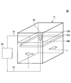
- FIG. 8 is a perspective view showing the pop-out prevention device in the present embodiment.
- FIG. 9 is a longitudinal sectional view of the pop-out prevention device of FIG.
- the pop-out prevention device 30 in the present embodiment is an electrode member 34a having the same shape as the electrode member 114a shown in the second embodiment of FIG. 4 and further inside the electrode member 34a of the water tank 11 as another electrode portion. It differs from the pop-out prevention device 10 in the first embodiment in that it includes an electrode portion 34 having a second electrode member 34 b disposed on the
- the pop-out prevention device 30 includes a water tank 11, a first electrode member 34a provided on the inner periphery of the water tank 11, and a second electrode member disposed further inside the first electrode member 34a. It has an electrode unit 34 having 34 b and a power supply unit 50 electrically connected to each of the first and second electrode members 34 a and 34 b of the electrode unit 34.
- the first electrode member 34 a is disposed below the water surface in the vicinity of the side wall portion 12 of the water tank 11. This first electrode member 34a can be disposed in the water tank 11 by any of the methods of the embodiments described above. For example, as shown in FIGS. 8 and 9, the first electrode member 34 a can be attached to the inner surface of the side wall 12.
- the first electrode member 34 a has the same configuration as the first electrode member 114 a shown in FIG. 6 and is disposed on the inner periphery of the water tank 11 and provided parallel to the water surface 100 in the water tank 11.
- the second electrode member 34 b is provided inside the first electrode member 34 a and is in contact with at least the water surface 100.
- the second electrode member 34b is point-like, and as shown in FIG. 9, can be provided inside the first electrode member 34a while being held by the floating portion 35.
- the second electrode member 34 b may be attached to the lower half of the floating portion 35.
- the floating portion 35 is made of a material that can float on the water surface 100 and is provided inside the water tank 11.
- the floating portion 35 has a cylindrical shape, and is disposed near the center of the water surface 100 in the water tank 11. Then, the floating portion 35 holds the second electrode member 34b while floating on the water surface 100, similarly to the floating portion 25 shown in FIG. 6, and maintains the underwater posture of the second electrode member 34b. Therefore, the second electrode member 34 b attached to the floating portion 35 moves integrally with the floating portion 35 in the depth direction.
- a connecting member (not shown) may be provided to connect the floating portion 35 floating on the water surface 100 and the bottom portion 13 of the water tank 11.
- the power supply unit 50 applies an electric pulse as shown in FIG. 3 described above (+ side) to the first electrode member 34 a on the outside (+ side), and the second electrode member 32 b on the inside Earth). Therefore, an electric field that stimulates aquatic organisms in a predetermined area near the inner circumferential surface near the water surface and swelling inward from the inner circumferential surface of the water tank 11 as described above around the first electrode 34a. e can be formed, and an area that does not attract aquatic organisms to be prevented from popping out as described above can be formed. Therefore, it is possible to prevent the aquatic organisms from jumping out of the water tank 11 by keeping the aquatic organisms out of such a region.
- the pop-out prevention device in the present embodiment includes the first electrode member 34 a provided on the side wall portion 12 and the second electrode member 34 b provided on the inside of the first electrode member 34 a.
- the second electrode member 34b of the first and second electrode members 34a and 34b can be disposed only by floating on the water surface, the electrode portion 34 can be easily installed.
- the shapes of the first electrode member 34a and the second electrode member 34b are not particularly limited as long as an electric field region can be formed in a desired region in water.
- the second electrode member 34a has a point or disc shape, but the second electrode member is formed by forming a linear member into a circular or polygonal ring shape. It may be Depending on the shape of the second electrode member 34a, the distance between the first electrode member 34a and the second electrode member 34b can be changed. For example, the outer diameter of the second electrode member 34b can be changed according to the size of the water tank 11, and the distance between the first and second electrode members 34a and 34b can be set as expected.
- the distance between both electrode members can be shortened, for example, even when the water tank 11 is large, an electric field of a necessary strength can be formed while limiting the strength of the electric pulse applied to the first electrode member.
- the 2nd electrode member 34b was comprised as one member was shown in this embodiment, several 2nd electrode members may be provided in the different position in the water tank 11. As shown in FIG.
- the second electrode member 34 b may be supported from above or below via the wiring 51 itself connected to the power supply 50 without the floating portion.
- the second electrode member 34b has a linear shape, be disposed in a direction intersecting the water surface, and at least a surface near the water surface be configured to be conductive. With such a configuration, when at least a part of the conductive surface is disposed below the water surface, the conductive surface can be brought into contact with water to function as the second electrode member 34 b.
- the water tank 11 shown in the first to third embodiments described above is disposed on land, and in addition to the pop-out prevention device according to the present invention, aquatic organisms such as the water quality and the amount of oxygen in the water tank 11 Various devices and the like can be provided to adjust the growth environment of the
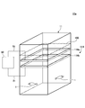
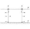
- FIG. 10 is a perspective view showing the pop-out prevention device in the present embodiment.
- 11 is a longitudinal sectional view of the protrusion prevention device of FIG.
- the pop-out prevention device 40 in the present embodiment is not provided in the water tank 11 as shown in FIGS. 1 and 2, but provided in the enclosure 42 installed in water as shown in FIGS. 10 and 11. In that it differs from the pop-out prevention device 10 in the first embodiment.
- the enclosure 42 functions as an enclosure that surrounds one or more aquatic organisms 1 in the horizontal direction or the horizontal direction, and includes and does not have a bottom lid covering the lower end of the enclosure.
- the enclosure which is the enclosure 42 is formed by a reticulated member having a mesh of such a size that the aquatic organism 1 can not pass through but the liquid can permeate, and is placed in water.
- it is a so-called shredded type culture aquaculture which is formed by a net in the sea or the like.
- the case where the inside of the water tank is divided by a net or the like also corresponds to the enclosed portion.
- the pop-out prevention device 40 includes an electrode portion 44 provided inside an enclosure portion 42 formed to surround the central axis X 42, and a power supply portion 50 connected to the electrode portion 44. Have.
- the floating portion 46 is configured to float on the water surface 100, and has an outer shape corresponding to the upper end opening of the surrounding portion 42 so that the surrounding portion 42 can be attached to the lower end.
- the floating portion 46 is formed of a material that can float on the water surface 100, such as a foamed plastic, and has a solid annular substantially rectangular cross section. There is.
- the surrounding portion 42 is attached to the lower end of the floating portion 46, and the floating portion 46 can hold the surrounding portion 42 while floating on the water surface 100. Further, when the surrounding portion 42 further includes the bottom lid 43 as described later, the floating portion 46 also holds the bottom lid 43 while floating on the water surface 100.
- the floating portion 46 may be configured to float on the water surface 100 by being formed in a hollow shape like a balloon or the like.
- the surrounding portion 42 is formed in a tubular shape made of a mesh-like member, and for example, as shown in FIG.
- the upper open end 42 a of the surrounding portion 42 is attached to the lower portion of the floating portion 46.
- the enclosure part 42 hold
- the surrounding portion 42 is supported near the water surface by the floating portion 46 at the upper open end 42 a of the surrounding portion 42 and extends downward from the water surface 100 toward the lower open end 42 b of the surrounding portion 42.
- the surrounding portion 42 surrounds and encloses a predetermined region 70 (hereinafter, also referred to as an internal space 70) in water over the depth direction.
- a predetermined region 70 hereinafter, also referred to as an internal space 70
- the enclosure 42 can enclose one or more aquatic organisms 1 in the interior space 70.
- the enclosure 42 is formed of a net for ginger, etc., and the mesh of the enclosure 42 is smaller than the size of the aquatic organism 1. Therefore, the surrounding portion 42 communicates with the internal space 70 and the outside 71 of the internal space 70 (hereinafter, also referred to as the external space 71) so as to allow water (or liquid / fluid) to pass therethrough.
- the movement of the aquatic organism 1 between the inner space 70 and the outer space 71 is blocked. Specifically, water flows from the inner space 70 to the outer space 71 through the surrounding portion 42 and flows from the outer space 71 to the inner space 70. Therefore, the height of the water surface inside the surrounding portion 42 and the height of the water surface outside the surrounding portion 42 are the same. Also, the aquatic organism 1 can not move back and forth between the inner space 70 and the outer space 71 through the enclosure 42.
- the enclosure portion 42 is a bottom cover 43 attached to the lower end. May further be included.
- the bottom cover 43 is attached to the lower open end 42 b of the enclosure 42 and closes the lower end of the enclosure 42.
- the bottom cover 43 is formed of a net for ginger, etc., similarly to the enclosure 42. Therefore, the aquatic organism 1 can not move between the inner space 70 and the outer space 71 when the bottom lid 43 is provided in the surrounding portion 42.
- the electrode portion 44 has at least two electrode members, and is provided along the inner side, particularly the inner periphery, of the surrounding portion 42 of the surrounding portion 42.
- the electrode portion 44 is provided above a half of the length between the upper end and the lower end of the surrounding portion 42 and in a predetermined water depth region below the water surface, and is disposed substantially parallel to the water surface 100.
- the electrode portion 44 is curved along the shape of a cross section perpendicular to the depth direction of the surrounding portion 42, and the semicircular first electrode member 44a and the semicircular first electrode member 44a are And 2 electrode members 44b.
- the outer side of the first electrode member 44a and the outer side of the second electrode member 44b are respectively attached to the inner surface of the surrounding portion 42, and the first electrode member 44a and the second electrode member 44b are disposed to face each other.
- the first electrode member 44 a and the second electrode member 44 b are electrically separated and provided, for example, at the same depth from the water surface 100.
- the electrode unit 44 is provided on the side farther from the lower end (bottom), that is, on the upper end side than the half of the length in the water depth direction between the upper end and the lower end of the surrounding portion 42. More preferably, it is provided between the water surface 100 and the bottom half of the bottom of the enclosure 42 to the water depth. More preferably, it is provided between the water surface 100 and a third of the water depth of the lower end of the surrounding portion 42.
- the electrode portion 44 is preferably provided in a water depth of 1 m or less, more preferably, for example, 1 cm or more, 3 cm or more, 5 cm or more, 50 cm or less, 30 cm or less, 20 cm or less, 10 cm or less, 5 cm or less, or a combination thereof. . When the depth from the water surface 100 to the electrode portion 44 is within the above range, the pop-out prevention device 40 can suppress the pop-out of the aquatic organism 1 to the outside of the surrounding portion 42.
- the electrode portion 44 is held by the floating portion 46 via the surrounding portion 42. Therefore, the electrode portion 44 can move along the depth direction with the floating portion 46 and the surrounding portion 42 while being immersed in water as the water surface 100 descends or ascends. For example, in the case where the enclosure portion 42 is installed in the sea or the like, if the electrode portion 44 can be moved along with the fluctuation of the water surface in this way, the electrode portion 44 is changed by the change of tide level and the wave strength. Since it can be prevented from coming out on the water surface, aquatic organisms can be more reliably prevented from jumping out of the surrounding portion 42.
- the power supply unit 50 is connected to the electrode unit 44 via the wiring unit 51, and applies an electrical pulse to the electrode unit 44.
- the power supply unit 50 can apply, for example, an electrical pulse as shown in FIG. 5 to the first electrode member 44a and the second electrode member 44b.
- an electric field e can be formed in a predetermined area that bulges inward from the inner circumferential surface of the surrounding portion 42 to stimulate aquatic organisms, and the aquatic life should be prevented from jumping as described above. It is possible to form an area that does not attract living things. Therefore, it is possible to prevent the aquatic organisms from jumping out of the water tank 11 by keeping the aquatic organisms out of such a region.
- each parameter of the electric pulse can be determined depending on the shape and size of the surrounding portion 42, the type and size of the aquatic organism, the water quality, and the like, as in the above-described embodiment.
- each parameter may be adjusted to change with time. For example, the frequency may change periodically or randomly within a predetermined frequency range.
- the pop-out prevention device 40 is installed outside the sea or the like like a fish farm.
- the electrode portion 44 When an electrical pulse is applied to the electrode portion 44, the electrode portion 44 forms an electric field in a desired area in the water surrounded by the surrounding portion 42.
- the electric field acts as an electrical barrier to the aquatic organism 1. Therefore, the aquatic organism 1 can be prevented from jumping out of the water surface 100 surrounded by the surrounding portion 42 to the outside of the surrounding portion 42.
- the electrode portion 44 attached to the surrounding portion 42 moves integrally with the floating portion 46 and the surrounding portion 42 in the depth direction, the depth between the electric field region formed by the electrode portion 44 and the water surface 100 The desired relative positioning of the directions is maintained. Therefore, even if the water surface 100 fluctuates, the pop-out prevention device 40 can exert the effect of preventing the floating out of the aquatic organism 1.
- the pop-out prevention device in the present embodiment has the floating portion 46 that holds the encircling portion 42 and the electrode portion 44. And the electrode part 44 moves along a depth direction with the floating part 46 and the surrounding part 42, being immersed in water. Therefore, even if the water surface 100 fluctuates, the effect of suppressing the jumping out of the aquatic organism 1 can be maintained.
- the amount of water in the inner space 70 ie, the amount of water in the region inside the enclosure 42 is constant. It is. Therefore, it is not necessary to adjust the amount of water in the area inside the enclosing unit 42, such as the addition of water to the area inside the enclosing unit 42 and the removal of water from the area.
- the shape, size, number of installation, etc. of the floating part are not particularly limited as long as the floating part 46 can hold the surrounding part 42 and the electrode part 44 while maintaining the underwater posture of the electrode part 44. .
- the electrode unit 44 includes the first electrode member 44a and the second electrode member 44b
- the installation configuration of the electrode unit 44 is particularly limited as long as the electrode unit 44 includes at least two electrode members. It is not something to be done.
- the shape of the electrode portion 44 is appropriately set in accordance with the cross-sectional shape of the enclosure portion 42.
- the electrode portion 44 may be attached to the inner surface of the surrounding portion 42 as shown in FIG. 12 or the floating portion 46 in which the electrode portion 44 is in contact with water. It may be attached to the part of
- the shape of the enclosure 42 is not particularly limited as long as it can surround one or more aquatic organisms 1 in the space inside the enclosure 42, and may be cylindrical as shown in FIG. It may be a square tube.
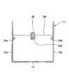
- FIG. 12 is a cross-sectional view showing a modified example of the pop-out prevention device in the present embodiment.
- the pop-out prevention device has a floating portion 46, an enclosing portion 42, an electrode portion 44, a power supply portion 50, and a fixing portion 47 attached to the lower end of the enclosing portion 42.
- the fixing portion 47 is made of a material that sinks in water, and is provided on the water bottom 101. Further, the fixing portion 47 is attached to the lower open end 42 b along the shape of the lower open end 42 b of the surrounding portion 42. For example, the fixing portion 47 is annular.
- the fixed portion 47 does not float due to the buoyancy of the floating portion 46, and the installation state of the fixed portion 47 with respect to the water bottom 101 is maintained, so the surrounding portion 42 is fixed to the water bottom 101 via the fixed portion 47. Therefore, the fixing portion 47 can avoid the drift of the pop-out prevention device.
- the water bottom 101 functions as the bottom cover 43 shown in FIGS. 11 and 12 with respect to the enclosure 42. Therefore, the pop-out prevention device fixed to the water bottom 101 can prevent the aquatic organism 1 from moving back and forth between the inner space 70 and the outer space 71 from the lower end side of the surrounding portion 42 without providing the bottom lid 43.
- jumping out of aquatic organisms can be prevented from a device such as a water tank or a ginger without installing a lid.
Landscapes
- Life Sciences & Earth Sciences (AREA)
- Environmental Sciences (AREA)
- Marine Sciences & Fisheries (AREA)
- Animal Husbandry (AREA)
- Biodiversity & Conservation Biology (AREA)
- Zoology (AREA)
- Engineering & Computer Science (AREA)
- Insects & Arthropods (AREA)
- Pest Control & Pesticides (AREA)
- Wood Science & Technology (AREA)
- Birds (AREA)
- Catching Or Destruction (AREA)
- Water Treatment By Electricity Or Magnetism (AREA)
- Farming Of Fish And Shellfish (AREA)
Abstract
Description
近年では、水槽外への水生生物の飛び出しを防止するために、蓋で水面の上方を覆うことができる水槽が開発されている。(例えば、特許文献1参照)。
第1実施形態における飛び出し防止装置について、図1~5に基づき説明する。図1は、本実施形態における飛び出し防止装置の概略を示す斜視図である。図2は、図1の飛び出し防止装置の縦断面図である。なお、各図面は見やすさに配慮して作図されているので、縦横のサイズは実際の縮尺とは異なる場合があり、部材ごとの縮尺も実際とは異なる場合がある。
また、電気パルスの周波数を、時間ごとに所定の周波数範囲の中で異ならせて印加することもできる。この周波数範囲としては、例えば、0.1~2.0kHz、0.5~1.5kHz、0.8~1.1kHz、0.5~1.0kHz等の範囲を適用することができる。周波数は、この周波数範囲の中を時間に応じて周期的に変化するように掃引されてもよいし、この周波数範囲の中からランダムに選択されるようにしてもよい。このように周波数を変化させて電極部14に電気パルスを印加すると、水生生物の種類や大きさによらず、飛び出しを防止することが可能になる。
同様に、電気パルスの電圧やデューティ比等の各パラメータを変化させながら、電気パルスを電極部14に印加することができる。
次に、第2実施形態における飛び出し防止装置について、図6及び図7に基づき説明する。図6は、本実施形態における飛び出し防止装置を示す斜視図である。図7は、図6の飛び出し防止装置の縦断面図である。
次に、第3実施形態における飛び出し防止装置について、図8及び図9に基づき説明する。図8は、本実施形態における飛び出し防止装置を示す斜視図である。図9は、図8の飛び出し防止装置の縦断面図である。
次に、第4実施形態における飛び出し防止装置について、図10及び図11に基づき説明する。図10は、本実施形態における飛び出し防止装置を示す斜視図である。図11は、図10のび出し防止装置の縦断面図である。
10 飛び出し防止装置
11 水槽
12 側壁部
13 底部
14 電極部
50 電源部
51 配線部
100 水面
Claims (8)
- 水生生物を飼育するための水槽の内周に設置された電極部と、
前記電極部に電気的に接続され、前記電極部に電気パルスを印加する電源部と、
を備えた、水生生物の飛び出し防止装置であって、
前記電極部は、前記水槽の前記内周の一部又は全部にわたって水平方向に延在し、前記水槽内の所定の水深領域に配置され、
前記電極部に電気パルスを印加する、水生生物の飛び出し防止装置。 - 前記電極部が、前記水槽の内周面に取り付けられている、請求項1記載の水生生物の飛び出し防止装置。
- 水面に浮くことができる浮き部をさらに備え、
前記電極部が、前記浮き部の下方に取り付けられている、請求項1記載の水生生物の飛び出し防止装置。 - 前記電極部が、前記水槽の高さ又は前記水槽内の水位の半分より上側の高さに設けられている、
請求項1記載の水生生物の飛び出し防止装置。 - 水生生物の周囲を取り囲んで包囲する筒状の包囲部の内周に設置された電極部と、
前記電極部に電気的に接続され、前記電極部に電気パルスを印加する電源部と、
を備えた、水生生物の飛び出し防止装置であって、
前記電極部は、前記包囲部の前記内周の一部又は全部にわたって水平方向に延在し、前記包囲部の高さの半分より上側の所定の水深領域に配置され、
前記電極部に電気パルスを印加する、水生生物の飛び出し防止装置。 - 水面に浮くことができる浮き部をさらに備え、
前記包囲部は、前記浮き部に取り付けられて、前記浮き部によって水中で支持されている、請求項5記載の水生生物の飛び出し防止装置。 - 前記電極部は前記包囲部に取り付けられることにより、前記包囲部を介して前記浮き部によって支持される、請求項6記載の水生生物の飛び出し防止装置。
- 前記電極部が、前記包囲部内の水位の半分より上側の高さに設けられている、
請求項5記載の水生生物の飛び出し防止装置。
Priority Applications (8)
| Application Number | Priority Date | Filing Date | Title |
|---|---|---|---|
| EP18842311.5A EP3662748B1 (en) | 2017-08-03 | 2018-07-06 | Device for preventing aquatic organisms from jumping out |
| JP2019534002A JP6635494B2 (ja) | 2017-08-03 | 2018-07-06 | 水生生物の飛び出し防止装置 |
| CN201880019188.0A CN110430750B (zh) | 2017-08-03 | 2018-07-06 | 水生生物跳出防止装置 |
| DK18842311.5T DK3662748T3 (da) | 2017-08-03 | 2018-07-06 | Indretning til at forhindre vandorganismer i at springe ud |
| US16/499,819 US11350613B2 (en) | 2017-08-03 | 2018-07-06 | Device for preventing aquatic organisms from jumping out |
| CA3058363A CA3058363C (en) | 2017-08-03 | 2018-07-06 | Device for preventing aquatic organisms from jumping out |
| ES18842311T ES2989794T3 (es) | 2017-08-03 | 2018-07-06 | Dispositivo para impedir que organismos acuáticos salten al exterior |
| PH12019502147A PH12019502147A1 (en) | 2017-08-03 | 2019-09-19 | Device for preventing aquatic organisms from jumping out |
Applications Claiming Priority (2)
| Application Number | Priority Date | Filing Date | Title |
|---|---|---|---|
| JP2017151082 | 2017-08-03 | ||
| JP2017-151082 | 2017-08-03 |
Publications (1)
| Publication Number | Publication Date |
|---|---|
| WO2019026548A1 true WO2019026548A1 (ja) | 2019-02-07 |
Family
ID=65232529
Family Applications (1)
| Application Number | Title | Priority Date | Filing Date |
|---|---|---|---|
| PCT/JP2018/025768 Ceased WO2019026548A1 (ja) | 2017-08-03 | 2018-07-06 | 水生生物の飛び出し防止装置 |
Country Status (9)
| Country | Link |
|---|---|
| US (1) | US11350613B2 (ja) |
| EP (1) | EP3662748B1 (ja) |
| JP (2) | JP6635494B2 (ja) |
| CN (1) | CN110430750B (ja) |
| CA (1) | CA3058363C (ja) |
| DK (1) | DK3662748T3 (ja) |
| ES (1) | ES2989794T3 (ja) |
| PH (1) | PH12019502147A1 (ja) |
| WO (1) | WO2019026548A1 (ja) |
Families Citing this family (2)
| Publication number | Priority date | Publication date | Assignee | Title |
|---|---|---|---|---|
| JP7346318B2 (ja) | 2020-01-31 | 2023-09-19 | 株式会社ダイヤメット | インサート焼結部品及びその製造方法 |
| CN113040084B (zh) * | 2021-03-23 | 2022-10-14 | 武汉大学 | 一种分析水中电流场对鱼类行为影响的实验装置 |
Citations (6)
| Publication number | Priority date | Publication date | Assignee | Title |
|---|---|---|---|---|
| JPS4941185U (ja) * | 1972-07-12 | 1974-04-11 | ||
| JPS55140359U (ja) * | 1979-03-29 | 1980-10-07 | ||
| JPH0358724A (ja) * | 1989-07-27 | 1991-03-13 | Hitachi Zosen Corp | 魚介類の遊泳遮断方法 |
| JPH0372830A (ja) * | 1989-08-10 | 1991-03-28 | Hitachi Zosen Corp | 魚介類鑑賞装置 |
| JP2005080589A (ja) | 2003-09-09 | 2005-03-31 | Pleco Corporation | 生物飼育用水槽 |
| JP2017151082A (ja) | 2015-12-18 | 2017-08-31 | ブルーカー アーイクスエス ゲーエムベーハーBruker AXS GmbH | 3つのビーム経路のための切り換えシステムを備えるx線光学アセンブリ、及び関連するx線回折装置 |
Family Cites Families (10)
| Publication number | Priority date | Publication date | Assignee | Title |
|---|---|---|---|---|
| JPS52878B2 (ja) | 1972-09-06 | 1977-01-11 | ||
| US5460123A (en) * | 1993-04-23 | 1995-10-24 | The United States Of America As Represented By The Secretary Of Agriculture | Electroshock repulsion of waterfowl, aquatic animals, and small mammals |
| CN1324563A (zh) * | 2000-05-24 | 2001-12-05 | 郭华 | 海洋养殖 |
| AUPR663301A0 (en) * | 2001-07-27 | 2001-08-16 | Seachange Technology Pty Ltd | Shark repelling device |
| CN201160418Y (zh) * | 2007-12-18 | 2008-12-10 | 曾艺 | 鱼跳龙门装置 |
| US8087384B2 (en) * | 2009-04-10 | 2012-01-03 | Kerry Smith | Systems and methods for boat anesthetization of aquatic animals |
| WO2010149862A1 (fr) * | 2009-06-26 | 2010-12-29 | Gymnokidi S.A.S. | Procede permettant de faire parler un poisson electrique |
| US20120124918A1 (en) * | 2010-05-18 | 2012-05-24 | William Bing Zimmerman | Parapet protector |
| GB201212382D0 (en) * | 2012-07-12 | 2012-08-22 | Ace Aquatec Ltd | Predator deterrent |
| US10285394B1 (en) * | 2015-10-21 | 2019-05-14 | United States Of America As Represented By Secretary Of The Navy | Floating pier, pinniped deterrent system |
-
2018
- 2018-07-06 CN CN201880019188.0A patent/CN110430750B/zh active Active
- 2018-07-06 DK DK18842311.5T patent/DK3662748T3/da active
- 2018-07-06 CA CA3058363A patent/CA3058363C/en active Active
- 2018-07-06 ES ES18842311T patent/ES2989794T3/es active Active
- 2018-07-06 WO PCT/JP2018/025768 patent/WO2019026548A1/ja not_active Ceased
- 2018-07-06 US US16/499,819 patent/US11350613B2/en active Active
- 2018-07-06 JP JP2019534002A patent/JP6635494B2/ja active Active
- 2018-07-06 EP EP18842311.5A patent/EP3662748B1/en active Active
-
2019
- 2019-09-19 PH PH12019502147A patent/PH12019502147A1/en unknown
- 2019-09-30 JP JP2019180519A patent/JP7217017B2/ja active Active
Patent Citations (6)
| Publication number | Priority date | Publication date | Assignee | Title |
|---|---|---|---|---|
| JPS4941185U (ja) * | 1972-07-12 | 1974-04-11 | ||
| JPS55140359U (ja) * | 1979-03-29 | 1980-10-07 | ||
| JPH0358724A (ja) * | 1989-07-27 | 1991-03-13 | Hitachi Zosen Corp | 魚介類の遊泳遮断方法 |
| JPH0372830A (ja) * | 1989-08-10 | 1991-03-28 | Hitachi Zosen Corp | 魚介類鑑賞装置 |
| JP2005080589A (ja) | 2003-09-09 | 2005-03-31 | Pleco Corporation | 生物飼育用水槽 |
| JP2017151082A (ja) | 2015-12-18 | 2017-08-31 | ブルーカー アーイクスエス ゲーエムベーハーBruker AXS GmbH | 3つのビーム経路のための切り換えシステムを備えるx線光学アセンブリ、及び関連するx線回折装置 |
Non-Patent Citations (1)
| Title |
|---|
| See also references of EP3662748A4 |
Also Published As
| Publication number | Publication date |
|---|---|
| PH12019502147A1 (en) | 2020-06-08 |
| JP2020014473A (ja) | 2020-01-30 |
| CN110430750A (zh) | 2019-11-08 |
| JPWO2019026548A1 (ja) | 2019-11-14 |
| EP3662748A1 (en) | 2020-06-10 |
| US20200100475A1 (en) | 2020-04-02 |
| US11350613B2 (en) | 2022-06-07 |
| EP3662748A4 (en) | 2021-04-07 |
| CA3058363C (en) | 2022-01-25 |
| JP7217017B2 (ja) | 2023-02-02 |
| CN110430750B (zh) | 2022-08-09 |
| CA3058363A1 (en) | 2019-02-07 |
| ES2989794T3 (es) | 2024-11-27 |
| EP3662748B1 (en) | 2024-06-19 |
| JP6635494B2 (ja) | 2020-01-29 |
| DK3662748T3 (da) | 2024-07-08 |
Similar Documents
| Publication | Publication Date | Title |
|---|---|---|
| JP6362056B2 (ja) | 水中生物を誘導する方法及び水中生物を誘導するシステム | |
| ES2947635T3 (es) | Control ultrasónico de algas | |
| NO346649B1 (en) | A device, system and method for trapping and killing marine organisms | |
| JP7217017B2 (ja) | 水生生物の飛び出し防止装置 | |
| KR200477010Y1 (ko) | 해삼 등의 어패류 및 해조류용 인공어초 | |
| JP6851057B2 (ja) | 電極装置 | |
| HK40031671A (en) | Device for preventing aquatic organisms from jumping out | |
| HK40031671B (en) | Device for preventing aquatic organisms from jumping out | |
| WO2018059674A1 (en) | A method for farming fish and an artificial barrier used for the method | |
| JP6868891B2 (ja) | 電極装置 | |
| KR200317180Y1 (ko) | 옆면에 구멍이 있는 원기둥으로 구현되는 터널식인공어초 구조물 | |
| KR20200098489A (ko) | 바다에서 수산양식 생물을 양식하기 위한 장치 | |
| JPH0347497Y2 (ja) | ||
| JPH0345575Y2 (ja) | ||
| JPH0345572Y2 (ja) | ||
| KR200350561Y1 (ko) | 인공 강재어초 | |
| CA3038644C (en) | A device, system and method for trapping and killing marine organisms | |
| JPH0347493Y2 (ja) | ||
| RU161355U1 (ru) | Универсальный электронный тренер рыб | |
| JP2004081112A (ja) | 浮子 | |
| HK1262722B (en) | Method for guiding underwater organisms, and system for guiding underwater organisms | |
| KR20130119052A (ko) | 어류생장촉진장치 | |
| JP2005137239A (ja) | 人工漁礁 | |
| PH12017050067A1 (en) | Fish pen | |
| KR20180077391A (ko) | 인공어초 |
Legal Events
| Date | Code | Title | Description |
|---|---|---|---|
| 121 | Ep: the epo has been informed by wipo that ep was designated in this application |
Ref document number: 18842311 Country of ref document: EP Kind code of ref document: A1 |
|
| ENP | Entry into the national phase |
Ref document number: 2019534002 Country of ref document: JP Kind code of ref document: A |
|
| ENP | Entry into the national phase |
Ref document number: 3058363 Country of ref document: CA |
|
| NENP | Non-entry into the national phase |
Ref country code: DE |
|
| ENP | Entry into the national phase |
Ref document number: 2018842311 Country of ref document: EP Effective date: 20200303 |