WO2019031403A1 - Dispositif optique - Google Patents
Dispositif optique Download PDFInfo
- Publication number
- WO2019031403A1 WO2019031403A1 PCT/JP2018/029201 JP2018029201W WO2019031403A1 WO 2019031403 A1 WO2019031403 A1 WO 2019031403A1 JP 2018029201 W JP2018029201 W JP 2018029201W WO 2019031403 A1 WO2019031403 A1 WO 2019031403A1
- Authority
- WO
- WIPO (PCT)
- Prior art keywords
- light
- wavelength
- emitted
- information
- optical device
- Prior art date
- Legal status (The legal status is an assumption and is not a legal conclusion. Google has not performed a legal analysis and makes no representation as to the accuracy of the status listed.)
- Ceased
Links
Images






Classifications
-
- G—PHYSICS
- G01—MEASURING; TESTING
- G01C—MEASURING DISTANCES, LEVELS OR BEARINGS; SURVEYING; NAVIGATION; GYROSCOPIC INSTRUMENTS; PHOTOGRAMMETRY OR VIDEOGRAMMETRY
- G01C3/00—Measuring distances in line of sight; Optical rangefinders
-
- G—PHYSICS
- G01—MEASURING; TESTING
- G01C—MEASURING DISTANCES, LEVELS OR BEARINGS; SURVEYING; NAVIGATION; GYROSCOPIC INSTRUMENTS; PHOTOGRAMMETRY OR VIDEOGRAMMETRY
- G01C3/00—Measuring distances in line of sight; Optical rangefinders
- G01C3/02—Details
- G01C3/06—Use of electric means to obtain final indication
-
- G—PHYSICS
- G01—MEASURING; TESTING
- G01S—RADIO DIRECTION-FINDING; RADIO NAVIGATION; DETERMINING DISTANCE OR VELOCITY BY USE OF RADIO WAVES; LOCATING OR PRESENCE-DETECTING BY USE OF THE REFLECTION OR RERADIATION OF RADIO WAVES; ANALOGOUS ARRANGEMENTS USING OTHER WAVES
- G01S7/00—Details of systems according to groups G01S13/00, G01S15/00, G01S17/00
- G01S7/48—Details of systems according to groups G01S13/00, G01S15/00, G01S17/00 of systems according to group G01S17/00
- G01S7/481—Constructional features, e.g. arrangements of optical elements
-
- G—PHYSICS
- G01—MEASURING; TESTING
- G01S—RADIO DIRECTION-FINDING; RADIO NAVIGATION; DETERMINING DISTANCE OR VELOCITY BY USE OF RADIO WAVES; LOCATING OR PRESENCE-DETECTING BY USE OF THE REFLECTION OR RERADIATION OF RADIO WAVES; ANALOGOUS ARRANGEMENTS USING OTHER WAVES
- G01S7/00—Details of systems according to groups G01S13/00, G01S15/00, G01S17/00
- G01S7/48—Details of systems according to groups G01S13/00, G01S15/00, G01S17/00 of systems according to group G01S17/00
- G01S7/497—Means for monitoring or calibrating
Definitions
- the present invention relates to an optical device that receives reflected light obtained by reflecting emitted light from an object.
- a band pass filter is used that transmits only light of the wavelength of the irradiated light.
- the N ratio is improved (see, for example, Patent Document 1).
- the band pass filter is used to cope with the wavelength fluctuation due to the temperature fluctuation of the light emitting element, it is to cope with the wavelength fluctuation of the light emitting element which it has. Therefore, when ambient light changes due to time zone, weather, etc., when the distribution or intensity of the wavelength of environmental light changes and the intensity of the same wavelength as the wavelength of the light emitting element increases, the reflected light of the light emitted by the light emitting element It may not be detected.
- One of the problems to be solved by the present invention is to cope with changes in the external environment as described above.
- the invention according to claim 1 made for the purpose of solving the above-mentioned problems is characterized in that irradiation means for irradiating the emitted light emitted from the emitting portion toward a predetermined range, and the emitted light exists in the predetermined range
- the light emitting unit emits light from the light emitting unit based on a light receiving unit that receives light reflected by an object and light including environmental light from a region including the object, and environmental light information that is information on the wavelength of the environmental light
- controlling means for controlling the wavelength or the light amount of the emitted light.
- FIG. 1st Example of this invention It is a schematic block diagram of the optical apparatus concerning the 1st Example of this invention. It is explanatory drawing which showed operation
- An optical device comprises: an irradiation unit that irradiates the emitted light emitted from the emitting portion toward a predetermined range; and the reflected light reflected by the object whose emitted light is present in the predetermined range And a light receiving unit that receives light including ambient light from a region including the target. Furthermore, it has a control means for controlling the wavelength or the light quantity of the emitted light emitted from the emitting unit based on the ambient light information which is the information on the wavelength of the ambient light. By doing this, ambient light information on the wavelength of ambient light can be obtained. Therefore, based on the information, it is possible to make the emitted light of the wavelength where the intensity of the environmental light is small. Therefore, the emitted light can be irradiated corresponding to the change of the external environment.
- the ambient light information may be information on the wavelength of the ambient light received by the light receiving unit when the emitting unit is not emitting the emitted light. By doing this, it is possible to obtain only information on the wavelength of ambient light.
- control means may change the wavelength of the ambient light to a wavelength smaller than the wavelength currently emitted by the emitting unit.
- the light receiving unit may have a plurality of light receiving elements and an optical element for guiding the light to any of the plurality of light receiving elements according to the wavelength of the incident light. By doing this, it is possible to easily acquire wavelength information of ambient light that has entered from the signals received by the plurality of light receiving elements.
- the optical device 1 includes the variable wavelength light source 2, the collimator lens 3, the beam splitter 4, the MEMS mirror 5, the light emitting and receiving lens 6, and the diffraction grating 7.
- a condenser lens 8, a line sensor 9, and a control unit 10 are provided.
- the variable-wavelength light source 2 as the emission unit is configured of a variable-wavelength light source capable of changing the emitted laser light to a wavelength in a predetermined wavelength range.
- the wavelength variable light source 2 one using a well-known Littrow external resonator or Littman external resonator may be mentioned, but other methods may be used without particular limitation.
- the wavelength variable light source 2 intermittently emits (irradiates) laser light as pulse light.
- the collimator lens 3 converts the laser light emitted from the variable wavelength light source 2 into a parallel light flux.
- the beam splitter 4 outputs the laser light collimated by the collimator lens 3 to the MEMS mirror 5 and reflects reflected light and environmental light, which will be described later, reflected by the MEMS mirror 5 toward the diffraction grating 7.
- the MEMS mirror 5 as an irradiation means scans the laser light transmitted through the beam splitter 4 in the horizontal direction and the vertical direction in the region where the object 100 is present. Further, the MEMS mirror 5 reflects, to the beam splitter 4, the incident light that the laser light or the like reflected by the object 100 has entered the light emitting and receiving lens 6.
- the MEMS mirror 5 is a mirror configured by MEMS (Micro Electro Mechanical Systems), and is driven by an actuator (not shown) integrally formed with the mirror. Also, the MEMS mirror 5 may be another beam deflection means such as a galvano mirror or a polygon mirror.
- the light emitting and receiving lens 6 irradiates (projects) the laser light reflected by the MEMS mirror 5 to the area where the object 100 exists. Further, reflected light of laser light from the object 100 and environmental light such as sunlight (including light which is reflected by the object 100) enter the light emitting and receiving lens 6 as incident light (received). Further, in this embodiment, it is assumed that laser light emitted from another optical device as ambient light and reflected light of the laser light reflected by the object are also included.
- the diffraction grating 7 as an optical element diffracts the incident light from the beam splitter 4 to the line sensor 9 at a diffraction angle corresponding to the wavelength component of the incident light.
- a transmission-type diffraction grating will be described, it may be a reflection-type diffraction grating.
- the condenser lens 8 is provided between the diffraction grating 7 and the line sensor 9 and condenses the incident light diffracted by the diffraction grating 7 onto the line sensor 9.
- the line sensor 9 is a light receiving sensor in which a plurality of light receiving elements are formed in a line along a direction in which light incident on the diffraction grating 7 is diffracted. Each of the plurality of light receiving elements receives light of the incident light diffracted by the diffraction grating 7 according to the wavelength component. Each light receiving element of the line sensor 9 outputs a signal corresponding to the intensity (received light intensity) of the received light to the control unit 10. Further, the line sensor 9 can be configured by, for example, an avalanche photodiode (APD) as a light receiving element.
- APD avalanche photodiode
- the control unit 10 as a control means detects the reflected light of the laser light emitted from the variable wavelength light source 2 based on the signal indicating the light reception intensity of each light receiving element of the line sensor 9. Further, when the variable wavelength light source 2 does not emit the laser light, the control unit 10 emits the laser from the variable wavelength light source 2 based on the result of the line sensor 9 receiving the environmental light incident from the light receiving and receiving lens 6. Determine the wavelength of light.
- FIG. 2 is an explanatory view of the operation at the time of emission (light emitting system).
- laser light emitted in a pulse form from the variable wavelength light source 2 is collimated by the collimator lens 3, and then passes through the beam splitter 4 and enters the MEMS mirror 5. Then, the laser beam reflected by the MEMS mirror 5 is irradiated toward the outside of the optical device 1 by the light emitting and receiving lens 6. At this time, by changing the angle of the MEMS mirror 5 at each irradiation timing, it is possible to temporally change the position of the beam spot to be irradiated toward the region where the object 100 exists, in the horizontal direction and A vertical scan is performed.
- FIG. 3 shows the operation at the time of incidence (light receiving system).
- the laser light reflected (scattered) by the object 100 follows the light path opposite to that at the time of light projection through the light receiving and receiving lens 6, is reflected by the MEMS mirror 5, and is reflected by the beam splitter 4. It is incident on.
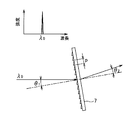
- the diffraction angle of the diffraction grating 7 is determined according to the groove pitch and the wavelength of the incident light.
- a laser beam is used, and the wavelength of the light incident on the diffraction grating 7 is single. Therefore, after being diffracted in a predetermined direction determined by the wavelength of the laser beam, the line sensor is conducted by the condensing lens 8 The light is collected on a predetermined light receiving element on the reference numeral 9.
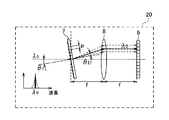
- the above-described diffraction grating 7, condenser lens 8, and line sensor 9 constitute an ambient light information acquiring unit 20 as a light receiving unit.
- the ambient light information acquisition unit 20 is configured of the diffraction grating 7, the condenser lens 8, and the line sensor 9.
- a spectroscope using a prism or the like is not limited.
- the configuration may be such that the spectrum of sunlight according to the season, the weather, or the difference in time is held in advance as a table, and is used as ambient light information.
- the light receiving unit may have a function of acquiring wavelength information of ambient light separately.
- the table is stored in storage means (not shown), and a table according to the season, weather, and time when using the optical device 1 is used. By doing so, the wavelength of the laser light can be selected based on appropriate sunlight spectrum information.
- the light incident on the light emitting and receiving lens 6 is not only the reflected light of the laser light emitted from the wavelength variable light source 2. Any light that illuminates the object 100 such as sunlight or light on the street, or light that is reflected by the object 100 enters the light emitting / receiving lens 6 and enters the diffraction grating 7 via the MEMS mirror 5 .
- Ambient light such as sunlight is light including various wavelengths, and is diffracted in various directions by the diffraction grating 7 and is incident on a plurality of light receiving elements on the line sensor 9 according to the included wavelength range.
- the operation of the diffraction grating 7 (the ambient light information acquiring unit 20) will be described in detail with reference to FIGS. 4 to 6.
- the diffraction angle ⁇ 2 when monochromatic light of wavelength ⁇ 0 is made incident on the diffraction grating 7 with a groove spacing p from the direction of the angle ⁇ 1 is expressed by the following equation (1).
- the diffraction grating 7 diffracts only a specific direction theta 2 in a situation for entering the monochromatic light (laser beam).
- diffracted light means + 1st order diffracted light unless otherwise specified.
- a blazed diffraction grating having a sawtooth-like groove shape is used as the diffraction grating. The use of a blazed diffraction grating is desirable because the diffraction efficiency of + 1st order light can be theoretically made 100% by the blazed diffraction grating.
- FIG. 1st order light can be theoretically made 100% by the blazed diffraction grating.
- a condenser lens 8 is provided to condense the diffracted light diffracted by the diffraction grating 7 on the line sensor 9.
- the focal length of the focusing lens 8 is f
- the distance from the diffraction grating 7 to the focusing lens 8 and the distance from the focusing lens 8 to the line sensor 9 are both located at the focal length f (see FIG. 6 and FIG. 7)
- the diffracted light diffracted in the direction in which the line sensors 9 are aligned at a predetermined diffraction angle is collected at one point on the line sensor 9.
- the incident light is monochromatic light (laser light)
- laser light laser light
- the reflected light of the laser light emitted from the wavelength variable light source 2 is incident only on a specific light receiving element on the line sensor 9, and the environmental light is a plurality of light receiving elements corresponding to the included wavelength components. It will be incident.
- the focal length f may be set to have appropriate wavelength resolution in accordance with the size of the line sensor 9 to be used and the number of light receiving elements.
- ambient light information acquisition unit 20 having such a configuration, when the wavelength of the laser light emitted from the wavelength variable light source 2 is lambda 0, a wavelength longer than lambda 0 in addition to the reflected light having a wavelength of lambda 0 lambda Suppose that light of 0 'enters. In this case, the diffraction angle of the incident light of wavelength ⁇ 0 is ⁇ 2 , the diffraction angle of the incident light of wavelength ⁇ 0 ′ is ⁇ 2 ′, and the light receiving position on the line sensor 9 as shown by the solid line and broken line in FIG. Changes. Therefore, by measuring and grasping the relationship between the light receiving position and the wavelength in advance, it is possible to distinguish between the reflected light of the laser beam emitted by itself and the environmental light.
- the environmental light information acquisition unit 20 acquires wavelength information of environmental light when the variable wavelength light source 2 does not emit laser light at the time of initial startup or the like. As a result of acquisition, for example, as shown in the graph of FIG. 7, the same position on the line sensor 9 when the peak wavelength of the ambient light (dotted line) and the wavelength of the own signal (solid line) are the same or very close. Therefore, the S / N is deteriorated, and the reflected light of the laser light can not be detected.
- the control unit 10 changes the wavelength of the laser light emitted by itself to ⁇ 3 based on the acquired wavelength information.
- the S / N can be improved because signals are received at different positions on the line sensor 9. That is, the control unit 10 uses wavelength information related to the wavelength of the environmental light received by the line sensor 9 (light receiving unit) of the environmental light information acquiring unit 20 when the variable wavelength light source 2 (emitting unit) does not irradiate the emitted light. Based on this, the wavelength of the outgoing light emitted from the variable wavelength light source 2 (emitting part) is changed.
- the control unit 10 changes the wavelength of the ambient light to a wavelength smaller than the wavelength currently emitted by the variable wavelength light source 2 (emission unit).
- the optical device 1 is reflected by the MEMS mirror 5 that irradiates the laser light emitted from the wavelength variable light source 2 toward the predetermined range, and the object 100 in which the laser light is present in the predetermined range And a line sensor 9 for receiving light including ambient light from a region including the object 100. Furthermore, when the variable wavelength light source 2 does not irradiate the laser light, the control unit 10 controls the wavelength or the light quantity of the laser light emitted from the variable wavelength light source 2 based on the environmental light information which is information on the wavelength of the environmental light. Have.
- control unit 10 changes the wavelength of the environmental light to a wavelength smaller than the wavelength currently irradiated by the variable wavelength light source 2.
- the S / N can be improved because the intensity of ambient light is reduced compared to the present.
- the ambient light information acquisition unit 20 includes a line sensor 9 having a plurality of light receiving elements, and a diffraction grating 7 for guiding the light to any of the plurality of light receiving elements according to the wavelength of the incident light. ,have. By doing this, it is possible to easily acquire wavelength information of ambient light that has entered from the signals received by the plurality of light receiving elements.
- the present optical device can use the distance to the object for measurement. That is, the CPU or the like of the distance measuring device on which the optical device is mounted measures the time from when the light source emits laser light to when it is received by the light receiving element as reflected light reflected by the object 100. The distance from the device to the object can be measured.
- the ambient light is mainly described as light for illuminating the object 100 such as sunlight or street light, but when the optical device 1 is mounted on a movable body such as a vehicle, it is other than the own vehicle
- the laser beam emitted from the optical device 1 mounted on another vehicle or the reflected light may be incident.
- the wavelength of the laser beam emitted by itself and the wavelength of the laser beam emitted by the other optical device are the same, the reflected light of the laser beam emitted by itself and the laser beam emitted by the other optical device or its reflected light May not be distinguishable and may malfunction. Therefore, laser light and reflected light from such other optical devices are regarded as environmental light, and the above-mentioned embodiment is applied to change its wavelength to a wavelength different from that of the other optical devices 1 and cause malfunction. Can be prevented.
- FIG. 10 and 11 show an example where laser light from another optical device and its reflected light are incident.
- the solid line in FIG. 10 indicates the reflected light of the laser beam emitted by itself, and the broken line indicates the ambient light.
- the peaks overlapping with the solid line indicate the wavelengths of the laser light from the other optical device and the reflected light thereof.
- the wavelength ( ⁇ 3 ) of the laser beam emitted by itself overlaps with the wavelength of the laser beam emitted by another optical device. That is, the same light receiving element of the line sensor 9 receives the reflected light.
- the control unit 10 of the other wavelengths of the variable wavelength light source 2 from lambda 3 optical wavelength and the peak of such wavelength and solar laser beam of the device is changed to not lambda 4 which overlap.
- the light receiving element different from the line sensor 9 receives the own signal and the other signal, which makes it possible to prevent a malfunction.
- an example of acquiring wavelength information of ambient light at the first activation is shown, but for example, in a cycle of scanning a predetermined area by the MEMS mirror 5, a cycle not to irradiate the laser light is provided
- the wavelength information of the ambient light may be acquired at the time.
- the wavelength of the emitted light emitted by the variable-wavelength light source 2 (the output unit) is changed based on the wavelength information on the wavelength of the environmental light, but the light amount of the emitted light to be emitted is adjusted ) To make it easy to distinguish between the ambient light and the reflected light of the laser light.
- the present invention is not limited to the above embodiment. That is, those skilled in the art can carry out various modifications without departing from the gist of the present invention in accordance with conventionally known findings. As long as the configuration of the optical device of the present invention is provided even by such a modification, it is of course included in the scope of the present invention.
- Optical device 2 Tunable light source (emitting part) 5 MEMS mirror (irradiation means) 7 Diffraction grating (light receiving part) 8 Condenser Lens (Receiver) 9 Line sensor (light receiving unit) 10 Control unit (control means) 100 objects
Landscapes
- Engineering & Computer Science (AREA)
- Physics & Mathematics (AREA)
- General Physics & Mathematics (AREA)
- Radar, Positioning & Navigation (AREA)
- Remote Sensing (AREA)
- Computer Networks & Wireless Communication (AREA)
- Electromagnetism (AREA)
- Measurement Of Optical Distance (AREA)
- Optical Radar Systems And Details Thereof (AREA)
Abstract
L'invention concerne un dispositif optique qui peut s'adapter à des changements dans l'environnement externe. Un dispositif optique (1) comprend : un miroir MEMS (5) qui diffuse une lumière laser émise par une source de lumière accordable en longueur d'onde (2) vers une région prescrite ; et un câble transducteur (9) qui reçoit une lumière comprenant une lumière réfléchie comprenant la lumière laser qui a été réfléchie par un objet cible (100) présent dans la région prescrite, et une lumière ambiante provenant d'une région comprenant l'objet cible (100). De plus, le dispositif optique (1) comprend une unité de commande (10) qui commande la longueur d'onde ou l'intensité lumineuse de la lumière laser émise par la source de lumière accordable en longueur d'onde (2), sur la base d'informations de lumière ambiante, qui concernent la longueur d'onde de la lumière ambiante lorsque la source de lumière accordable en longueur d'onde (2) ne diffuse pas la lumière laser.
Applications Claiming Priority (2)
| Application Number | Priority Date | Filing Date | Title |
|---|---|---|---|
| JP2017-154934 | 2017-08-10 | ||
| JP2017154934 | 2017-08-10 |
Publications (1)
| Publication Number | Publication Date |
|---|---|
| WO2019031403A1 true WO2019031403A1 (fr) | 2019-02-14 |
Family
ID=65271534
Family Applications (1)
| Application Number | Title | Priority Date | Filing Date |
|---|---|---|---|
| PCT/JP2018/029201 Ceased WO2019031403A1 (fr) | 2017-08-10 | 2018-08-03 | Dispositif optique |
Country Status (1)
| Country | Link |
|---|---|
| WO (1) | WO2019031403A1 (fr) |
Cited By (2)
| Publication number | Priority date | Publication date | Assignee | Title |
|---|---|---|---|---|
| JPWO2021260950A1 (fr) * | 2020-06-26 | 2021-12-30 | ||
| WO2021260949A1 (fr) * | 2020-06-26 | 2021-12-30 | 三菱電機株式会社 | Dispositif de balayage optique et appareil de mesure de distance |
Citations (5)
| Publication number | Priority date | Publication date | Assignee | Title |
|---|---|---|---|---|
| JP2009222690A (ja) * | 2008-03-19 | 2009-10-01 | Soma Kogaku:Kk | 分光測定器及び分光測定方法 |
| WO2010021090A1 (fr) * | 2008-08-20 | 2010-02-25 | パナソニック株式会社 | Dispositif d'estimation de distance, procédé d'estimation de distance, programme, circuit intégré et caméra |
| WO2010137174A1 (fr) * | 2009-05-29 | 2010-12-02 | トヨタ自動車 株式会社 | Appareil de mesure de spectre pour chargeur |
| US20140253688A1 (en) * | 2013-03-11 | 2014-09-11 | Texas Instruments Incorporated | Time of Flight Sensor Binning |
| JP2016053566A (ja) * | 2014-09-03 | 2016-04-14 | パナソニックIpマネジメント株式会社 | 測定システム |
-
2018
- 2018-08-03 WO PCT/JP2018/029201 patent/WO2019031403A1/fr not_active Ceased
Patent Citations (5)
| Publication number | Priority date | Publication date | Assignee | Title |
|---|---|---|---|---|
| JP2009222690A (ja) * | 2008-03-19 | 2009-10-01 | Soma Kogaku:Kk | 分光測定器及び分光測定方法 |
| WO2010021090A1 (fr) * | 2008-08-20 | 2010-02-25 | パナソニック株式会社 | Dispositif d'estimation de distance, procédé d'estimation de distance, programme, circuit intégré et caméra |
| WO2010137174A1 (fr) * | 2009-05-29 | 2010-12-02 | トヨタ自動車 株式会社 | Appareil de mesure de spectre pour chargeur |
| US20140253688A1 (en) * | 2013-03-11 | 2014-09-11 | Texas Instruments Incorporated | Time of Flight Sensor Binning |
| JP2016053566A (ja) * | 2014-09-03 | 2016-04-14 | パナソニックIpマネジメント株式会社 | 測定システム |
Cited By (6)
| Publication number | Priority date | Publication date | Assignee | Title |
|---|---|---|---|---|
| JPWO2021260950A1 (fr) * | 2020-06-26 | 2021-12-30 | ||
| WO2021260949A1 (fr) * | 2020-06-26 | 2021-12-30 | 三菱電機株式会社 | Dispositif de balayage optique et appareil de mesure de distance |
| JPWO2021260949A1 (fr) * | 2020-06-26 | 2021-12-30 | ||
| WO2021260950A1 (fr) * | 2020-06-26 | 2021-12-30 | 三菱電機株式会社 | Dispositif de balayage optique et appareil de télémétrie |
| JP7109673B2 (ja) | 2020-06-26 | 2022-07-29 | 三菱電機株式会社 | 光走査デバイス及び測距装置 |
| CN115917358A (zh) * | 2020-06-26 | 2023-04-04 | 三菱电机株式会社 | 光扫描设备和测距装置 |
Similar Documents
| Publication | Publication Date | Title |
|---|---|---|
| JP6857734B2 (ja) | 光学装置 | |
| US11019326B2 (en) | Light-source characterizer and associated methods | |
| JP7117437B2 (ja) | 光学装置 | |
| US11703571B2 (en) | Optical device | |
| RU2015116588A (ru) | Спектроскопическое измерительное устройство | |
| JP6493018B2 (ja) | レーザ測距装置 | |
| WO2019031327A1 (fr) | Appareil optique | |
| US9594253B2 (en) | Spectral apparatus, detection apparatus, light source apparatus, reaction apparatus, and measurement apparatus | |
| WO2019031403A1 (fr) | Dispositif optique | |
| US9945656B2 (en) | Multi-function spectroscopic device | |
| WO2019017245A1 (fr) | Dispositif optique | |
| JP6876811B2 (ja) | 光学装置 | |
| US20230400582A1 (en) | Coherent sensing system using a DOE | |
| JP2024019680A (ja) | 走査装置及び光検出装置 | |
| JP2020046341A (ja) | 投光装置、投受光装置及び測距装置 | |
| JP5454942B2 (ja) | 分光装置とそれを用いた顕微鏡 | |
| JP2002310796A (ja) | 回折格子型マルチチャネル分光器およびその調整方法 | |
| JP2020012782A (ja) | 波面計測装置、波面計測方法、および、製造方法 | |
| JP2016133473A (ja) | 光学分析装置 | |
| JP2021124418A (ja) | 測距装置 | |
| JP2005172820A (ja) | 光電測定装置 |
Legal Events
| Date | Code | Title | Description |
|---|---|---|---|
| 121 | Ep: the epo has been informed by wipo that ep was designated in this application |
Ref document number: 18844594 Country of ref document: EP Kind code of ref document: A1 |
|
| NENP | Non-entry into the national phase |
Ref country code: DE |
|
| 122 | Ep: pct application non-entry in european phase |
Ref document number: 18844594 Country of ref document: EP Kind code of ref document: A1 |
|
| NENP | Non-entry into the national phase |
Ref country code: JP |