WO2019031476A1 - Récipient - Google Patents
Récipient Download PDFInfo
- Publication number
- WO2019031476A1 WO2019031476A1 PCT/JP2018/029525 JP2018029525W WO2019031476A1 WO 2019031476 A1 WO2019031476 A1 WO 2019031476A1 JP 2018029525 W JP2018029525 W JP 2018029525W WO 2019031476 A1 WO2019031476 A1 WO 2019031476A1
- Authority
- WO
- WIPO (PCT)
- Prior art keywords
- side plates
- container
- handle
- belt
- holding portion
- Prior art date
- Legal status (The legal status is an assumption and is not a legal conclusion. Google has not performed a legal analysis and makes no representation as to the accuracy of the status listed.)
- Ceased
Links
Images


Classifications
-
- B—PERFORMING OPERATIONS; TRANSPORTING
- B65—CONVEYING; PACKING; STORING; HANDLING THIN OR FILAMENTARY MATERIAL
- B65D—CONTAINERS FOR STORAGE OR TRANSPORT OF ARTICLES OR MATERIALS, e.g. BAGS, BARRELS, BOTTLES, BOXES, CANS, CARTONS, CRATES, DRUMS, JARS, TANKS, HOPPERS, FORWARDING CONTAINERS; ACCESSORIES, CLOSURES, OR FITTINGS THEREFOR; PACKAGING ELEMENTS; PACKAGES
- B65D25/00—Details of other kinds or types of rigid or semi-rigid containers
- B65D25/28—Handles
Definitions
- the present invention relates to a container provided with a handle.
- Patent Document 1 shows a container (touring box) including a rectangular bottom portion, front and rear, left and right side wall portions corresponding to each side of the bottom portion, and a lid portion, and the outside of the left and right side wall portions Are disclosed in which a handle is provided.
- Patent Document 1 when the container is lifted, a large load is applied to the root (the attachment portion of the handle and the side wall) of the handle and the handle may come off, or the handle and the side wall are attached There was a possibility that the part might be damaged.
- This invention is made in view of such a situation, and provides the container which can reduce the load applied to the root of a handle.
- the container further includes a bottom wall, a side wall, and a container having a handle, the belt being wound around the lower surface of the bottom wall, and the side wall includes a holding portion for passing the belt.
- a container is provided, the handle being connected to a belt pulled out of the holder on the upper side of the holder.
- the load of the container is distributed to the bottom of the container, since the handle is attached to the belt and the belt is configured to be wound around the lower surface of the bottom wall of the container to hold the container bottom. It will be applied to the belt, making it possible to reduce the load on the base of the hand.
- the holding part comprises left and right holding parts
- the holding hand comprises left and right holding hands
- the left and right holding hands are respectively pulled out from the left and right holding parts
- the left and right holding portions are provided to face each other on the side wall.
- one end of the belt is pulled out of the left holding portion and the other end is pulled out of the right holding portion.
- the belt includes front and back belts
- the holding unit includes a front holding unit and a rear holding unit
- the front and rear belts are respectively pulled out from the front holding unit and the rear holding unit
- the front end and the rear end of the handle are connected to the front and rear belts, respectively.
- the bottom wall includes a substantially rectangular bottom plate
- the side walls include left and right side plates connected to one opposite side of the bottom plate, and front and rear side plates connected to the other opposite side of the bottom plate.
- the holding portion is provided on each of the left and right side plates.
- the left and right side plates and the front and rear side plates are respectively connected to the bottom plate so as to be able to stand upright.
- the belt is configured to be connected to the handle in a state of being pulled out from the holding portion by a predetermined length when the left and right side plates rise.
- the lid which closes the accommodation space formed of the bottom wall and the side wall, and the bottom wall, the side wall and the lid are formed of a foamed resin.
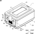
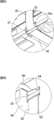
- FIG. 4A is a front view of the lid 10 of the container as viewed from the short side
- FIG. 4B is a front view of the container body 20 as viewed from the left and right side plates 50.
- FIG. 10A to 10C are explanatory views showing an operation of folding the left and right side plates 50 of the container of FIG. 11A to 11D are schematic views showing the bottom plate 30 and the left and right side plates 50 of the container 1 according to the modification of the present invention, respectively.
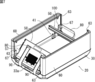
- the container 1 of this embodiment has a rectangular parallelepiped container body 20 having a bottom wall 3 and a side wall 4 as shown in FIGS. 1 and 2, and a lid 10 for closing the accommodation space S (see FIG. 2) of the container body 20. And Further, as shown in FIGS. 2 and 3, the container 1 has a pair of left and right handles 80 (left and right handles in the claims) disposed at opposite positions of the side walls, and the pair of handles And 80 two front and rear belts 90 (front and back belts in the claims).
- the direction of the side wall 4 provided with the handle 80 is the left-right direction
- the direction of the side wall 4 without the handle 80 is the front-back direction
- the side of the accommodation space S is the inside (inward direction)
- the opposite side is Outside (outside).
- the container 1 of this embodiment is a foldable container in which each side wall 4 is connected to the bottom wall 3 in a fallable manner.
- the container 1 of this embodiment is comprised as a cold storage container (or heat retention container) which maintains the temperature of a thing to be stored. Therefore, each member of the lid 10 and the container body 20 is preferably made of foamed resin, and a heat insulating material may be provided on the inner surface of the container or the like.
- the inner surface of the container made of a foamed resin
- the outer surface of the container made of a foamed resin it is possible to improve the impact resistance in addition to the improvement of the heat insulation (cooling and heat retention). It is also possible to partially provide a foamed resin for each member.
- the lid 10 is a member having a rectangular planar shape and a predetermined thickness, as shown in FIGS. 1 and 4A.
- a rectangular annular annular convex portion 11 in which the central portion is recessed is formed, and at the central portion of each short side of the lid 10, a fastening member 12 for fastening the lid 10 and the container body 20 is attached There is.
- the lower surface of the lid 10 is formed with a downwardly projecting lower convex portion 15 having a contour smaller than the contour of the lid 10.
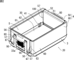
- the container body 20 includes a bottom plate 30 having a rectangular planar shape that constitutes the bottom wall 3, and a pair of left and right side plates 50 and a pair of front and rear side plates 60 that constitute the side wall 4.
- the left and right side plates 50 have the same configuration on the left and right
- the front and rear side plates 60 have the same configuration on the front and rear.
- the width in the front-rear direction of the left and right side plates 50 is shorter than the width in the left-right direction of the front and rear side plates 60.
- the left and right side plates 50 and the front and rear side plates 60 are connected to the bottom plate 30 so as to be upright and fall over, and are foldable.
- the bottom plate 30 has a bottom portion 31 having a rectangular planar shape, and a pair of opposing left and right side peripheral wall portions 33 and a pair of front and rear side peripheral wall portions 34 rising from the periphery of the top surface of the bottom portion 31.
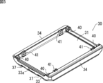
- Connecting members 40 are provided at both ends of the left and right side peripheral wall portions 33 for connecting the left and right side plates 50 so as to be able to stand upright and fall over, and the front and rear side plates 60 can be erected freely over the width near both ends of each front and rear side peripheral wall portion 33
- a connecting member 41 is provided for connecting to the
- the configuration of the connecting member 40 and the connecting member 41 and the configuration of the engaging portion between the peripheral wall portions 33 and 34 and the side plates 50 and 60 may be any known configuration, and the detailed description thereof will be omitted.
- the height of the left and right side peripheral wall portions 33 is lower than that of the front and rear side peripheral wall portions 34.
- a locking portion 33a is formed for locking the locking member 12 of the lid 10 when folded.
- simple structures such as a velcro, a magnet, concavo-convex latching, concavo-convex fitting, can be used.
- the bottom plate 30 is formed on the lower surface thereof in the vicinity of the connection portion of the long side and the short side, and a pair of front and rear convex portions 35a extending in the longitudinal direction near the front and rear side peripheral wall portion 33. It has four corner projections 35b and a central projection 35c formed in the central portion.
- the containers 1 are stacked by the front and rear convex portions 35a, the corner projections 35b, and the central convex portion 35c, they are stacked by fitting with the concave annular convex portion 11 of the central portion formed on the upper surface of the lid 10. The containers 1 are stabilized with each other.
- both grooves 36 extending to both ends in the longitudinal direction are formed on the lower surface of the bottom plate 30, and a belt 90 described later is accommodated in the grooves 36.
- the groove 36 may not have a depth at which the belt 90 is completely accommodated.
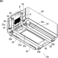
- both ends of the groove 36 are notches 36a inclined in the direction of the left and right side peripheral wall portions 33, and a rod-like holding portion 37 for passing and holding the belt 90 is stretched over the notches 36a.
- a concave portion 38 is formed in which a fingertip can be inserted when carrying the container 1 in a folded state (see FIG. 3).
- the left and right side plates 50 are members having a substantially rectangular planar shape, and are configured to be able to be folded in the inward direction of the container 1 by the connecting member 40.
- the width in a front view of the left and right side plates 50 is smaller than the width of the left and right side peripheral wall portion 33 of the bottom plate 30 by about twice the thickness of the front and rear side plates 60. This is to avoid interference between the side plates at the time of folding by the thickness of each of the left and right side plates 50 and the front and rear side plates 60.
- an inner end surface 52 one step lower than the end surface 51 is formed inside the upper end surface 51 of the left and right side plates 50 so as to fit with the lower convex portion 15 of the lid 10.
- the recessed part 57 is formed in the both ends of the right and left side plate 50, and it comes to engage with the convex part 67 of the overhang part 63 of the front and back side plate 60 mentioned later. ing. When the left and right side plates 50 are folded, the left and right side plates 50 do not interfere with the connecting member 41 (see FIGS. 2 and 7).
- FIGS. 6A and 6B On the outer surface of the left and right side plates 50, as shown in FIGS. 6A and 6B, two grooves extending upward from the lower end so as to be continuous with the grooves 36 and the notches 36a of the bottom plate 30 53 are formed. Further, a concave portion 54 deeper than the groove 53 is formed at the upper end of the groove 53 at a substantially intermediate position between the central portion in the height direction and the upper end (but not penetrating into the container). A rod-like holding portion 55 for passing and holding the belt 90 is bridged. A locking portion 56 for locking the locking member 12 of the lid 10 is formed at a central portion near the upper end of the outer surface of the left and right side plates 50. As a structure of the latching
- locking part 56 simple structures, such as a velcro, a magnet, concavo-convex latching, concavo-convex fitting, can be used.
- the front and rear side plates 60 are members having a substantially rectangular planar shape, and are configured to be able to be folded in the inward direction of the container 1 by the connecting member 41.
- the width in the left-right direction of the front and rear side plates 60 is equal to the length of the front and rear side peripheral wall portion 34 of the bottom plate 30.
- An inner end surface 62 lower than the end surface 61 is formed on the inside of the upper end surface 61 of the front and rear side plates 60 so as to be fitted to the lower convex portion 15 of the lid 10. As shown in FIG.
- the height of the upper end surface 61 is the same as the height of the upper end surface 51 of the left and right side plates 50
- the height of the inner end surface 62 is the same as the height of the inner end surface 52 of the left and right side plates 50.
- an overhanging portion 63 slightly overhanging along the left and right side peripheral wall portions 33 of the bottom plate 30 is formed at both ends of the front and rear side plates 60.
- a convex portion 67 is formed on part of the end face.
- the left and right side plates 50 and the front and rear side plates 60 are erected, the end face of the projecting portion 63 and the end face of the left and right side plate 50 are engaged, and the convex portion 67 of the overhanging portion 63 and the concave portion 57 of the left and right side plate 50 are engaged.
- the left and right side plates 50 and the front and back side plates 60 are fixed at the corner of the container body 20 in the vicinity of the position where the concave portion 57 and the convex portion 67 are formed.
- the lock mechanism 100 is formed.
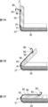
- the belt 90 is a belt-like member made of a material (cloth, rubber, cord, etc.) having a strength capable of supporting the container 1 together with the contents, and as shown in FIG. 2 and FIG. It is routed from the outer surface through the lower surface of the bottom plate 30 to the outer surfaces of the other left and right side plates 50.
- two belts 90 are arranged side by side in the front-rear direction, and are accommodated in the groove 53 and the groove 36 on the lower surface of the bottom plate 30 and the outer surface of the left and right side plates 50, respectively. As shown in FIGS.
- one end and the other end of the two belts 90 pass through the holding portions 37 on the lower surface of the bottom plate 30, respectively, and then upward from the holding portions 55 provided on the left and right side plates 50. And each connected to the end of the handle 80.
- the belt 90 is connected to the handle 80 in a state of being pulled out from the holding portion 55 by a predetermined length.
- the predetermined length of the belt 90 pulled out from the holding portion 55 is half or more of the thickness of the left and right side plates 50. The predetermined length is appropriately set from the thickness of the left and right side plates 50 and the configuration of the connecting member 40 (the position of the rotation shaft, etc.).
- the handle 80 is for carrying the container 1 in the assembled state, and is disposed outside the left and right side plates 50 as shown in FIG.
- the handle 80 is formed by bending a material having the same width as the belt 90 in half along the longitudinal direction (see FIG. 6B), and the belt has two ends (front end and rear end). It is connected with 90.
- the handle 80 of the cloth material is not limited to being folded in two, and may be folded in three, for example.
- a cover can be attached to the handle 80.
- the handle 80 may be made of a material different from the belt 90.
- the handle 80 indirectly supports the load of the container 1 via the belt 90.
- the handle 80 is directly attached to the side wall (the left and right side plates 50 and the like)
- the base portion of the handle 80 is broken, and the load on the container 1 can be reduced.
- the bottom of the container 1 is supported by the two belts, it is also possible to improve the stability when lifted.
- the thickness of the band 90 is drawn thicker than the actual thickness for the sake of clarity.
- the belt 90 wound around the lower surface of the bottom plate 30, the left and right side peripheral wall portions 33, and the outer surfaces of the left and right side plates 50 may be stretched, and the left and right side plates 50 may not be completely overturned.
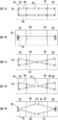
- the belt 90 of the present embodiment is connected to the handle 80 in a state of being pulled out from the holding portion 55 by a predetermined length (see the symbol d in FIG. 10A) when the left and right side plates 50 stand. Therefore, along with the rotation of the left and right side plates 50, the belt 90 pulled out from the holding portion 55 is pulled back, and increases between the upper outer end P1 of the left and right side peripheral wall 33 and the lower outer end P2 of the left and right side plates 50. By compensating for the distance, the left and right side plates 50 can be completely turned over.
- the front and rear side plates 60 are turned with respect to the bottom plate 30 (the connecting member 41) to be turned over.
- the left and right side plates 50 and the handle 80 are covered by the front and rear side plates 60.
- the lid 10 is placed on the folded front and rear side plates 60, and the fastening member 12 is engaged with the engaging portions 33a of the left and right side peripheral wall portions 33 to complete the folding operation (see FIG. 9). ).
- the lid 10 is first removed, and the front and rear side plates 60 are erected, and then the left and right side plates 50 are erected. And complete the container 1.
- this embodiment can also be implemented in the following modes.
- the pair of handles 80 disposed outside of the two opposite left and right side plates 50 are connected by the belt 90 passing through the lower surface of the bottom plate 30, but the belt 90 is one handle It does not have to be continuous on the lower surface of the bottom plate 30 from the side of 80 to the side of the other handle 80. That is, as shown in the developed view of FIG. 11A, the end of the belt 90 not connected to the handle 80 may be fixed by the fixing member 39 provided on the lower surface of the bottom plate 30.
- two belts 90 are provided, and one end and the other end of the handle 80 are connected to the two belts 90. However, as shown in FIG.
- the container 1 was a rectangular solid thing, it can also be set as other shapes, such as a column shape.
- the right and left grips 80 are provided, but it is also possible to provide only one grip 80 and directly support the container without providing a grip on one side.
- the handle 80 is provided in the direction of the left and right side plates 50, but may be provided in the direction of the front and rear side plates 60.
Landscapes
- Engineering & Computer Science (AREA)
- Mechanical Engineering (AREA)
- Rigid Containers With Two Or More Constituent Elements (AREA)
- Details Of Rigid Or Semi-Rigid Containers (AREA)
Abstract
L'invention concerne un récipient conçu de telle sorte qu'une charge agissant sur la base d'une poignée peut être réduite. Ce récipient comporte une paroi inférieure, des parois latérales, et une poignée est en outre pourvue d'une courroie qui s'étend à partir de la surface inférieure de la paroi inférieure. Une paroi latérale est pourvue d'une section de maintien à travers laquelle la courroie est passée. La poignée est reliée, au-dessus de la section de maintien, à la courroie étendue à l'extérieur de la section de maintien.
Applications Claiming Priority (2)
| Application Number | Priority Date | Filing Date | Title |
|---|---|---|---|
| JP2017-155589 | 2017-08-10 | ||
| JP2017155589A JP6889370B2 (ja) | 2017-08-10 | 2017-08-10 | 容器 |
Publications (1)
| Publication Number | Publication Date |
|---|---|
| WO2019031476A1 true WO2019031476A1 (fr) | 2019-02-14 |
Family
ID=65272014
Family Applications (1)
| Application Number | Title | Priority Date | Filing Date |
|---|---|---|---|
| PCT/JP2018/029525 Ceased WO2019031476A1 (fr) | 2017-08-10 | 2018-08-07 | Récipient |
Country Status (2)
| Country | Link |
|---|---|
| JP (1) | JP6889370B2 (fr) |
| WO (1) | WO2019031476A1 (fr) |
Families Citing this family (1)
| Publication number | Priority date | Publication date | Assignee | Title |
|---|---|---|---|---|
| WO2020175286A1 (fr) | 2019-02-27 | 2020-09-03 | Canon Kabushiki Kaisha | Système de gestion pour gérer un enregistrement de processus de stérilisation, appareil de traitement d'informations, procédé de gestion et support de stockage lisible par ordinateur |
Citations (7)
| Publication number | Priority date | Publication date | Assignee | Title |
|---|---|---|---|---|
| JPS5186330U (fr) * | 1974-12-27 | 1976-07-10 | ||
| JPS642788U (fr) * | 1987-06-25 | 1989-01-10 | ||
| JPH0542144U (ja) * | 1991-06-26 | 1993-06-08 | 鐘淵化学工業株式会社 | 手提げ紐つき断熱容器 |
| JPH11263346A (ja) * | 1998-03-18 | 1999-09-28 | Daiko Shiki:Kk | 運送用吊り下げ箱 |
| JP2001322637A (ja) * | 2000-05-16 | 2001-11-20 | Sanko Co Ltd | 折り畳みコンテナー |
| JP2002104426A (ja) * | 2000-09-27 | 2002-04-10 | Kanegafuchi Chem Ind Co Ltd | 手提げ紐付き容器 |
| US7815024B1 (en) * | 2007-04-02 | 2010-10-19 | Quimpo Wilfredo B | Collapsible balikbayan box apparatus |
-
2017
- 2017-08-10 JP JP2017155589A patent/JP6889370B2/ja active Active
-
2018
- 2018-08-07 WO PCT/JP2018/029525 patent/WO2019031476A1/fr not_active Ceased
Patent Citations (7)
| Publication number | Priority date | Publication date | Assignee | Title |
|---|---|---|---|---|
| JPS5186330U (fr) * | 1974-12-27 | 1976-07-10 | ||
| JPS642788U (fr) * | 1987-06-25 | 1989-01-10 | ||
| JPH0542144U (ja) * | 1991-06-26 | 1993-06-08 | 鐘淵化学工業株式会社 | 手提げ紐つき断熱容器 |
| JPH11263346A (ja) * | 1998-03-18 | 1999-09-28 | Daiko Shiki:Kk | 運送用吊り下げ箱 |
| JP2001322637A (ja) * | 2000-05-16 | 2001-11-20 | Sanko Co Ltd | 折り畳みコンテナー |
| JP2002104426A (ja) * | 2000-09-27 | 2002-04-10 | Kanegafuchi Chem Ind Co Ltd | 手提げ紐付き容器 |
| US7815024B1 (en) * | 2007-04-02 | 2010-10-19 | Quimpo Wilfredo B | Collapsible balikbayan box apparatus |
Also Published As
| Publication number | Publication date |
|---|---|
| JP6889370B2 (ja) | 2021-06-18 |
| JP2019034745A (ja) | 2019-03-07 |
Similar Documents
| Publication | Publication Date | Title |
|---|---|---|
| US7228575B2 (en) | Playpen assembly | |
| JP2012502256A (ja) | 積み重ね可能な携帯クーラーボックスシステム | |
| JP6146065B2 (ja) | ロール体用コンテナ | |
| KR100776420B1 (ko) | 영상 디스플레이 기기용 스탠드 | |
| US20220279925A1 (en) | Storage case | |
| WO2019031476A1 (fr) | Récipient | |
| JP2002087483A (ja) | 卵の多段式保持具 | |
| JP6530682B2 (ja) | 合成樹脂製折り畳み容器 | |
| CN112874981B (zh) | 可折叠保温箱 | |
| JP2014069868A (ja) | 容器 | |
| KR101572778B1 (ko) | 조립식 상자 | |
| KR20090007636U (ko) | 운반 및 보관이 용이한 접철식 바구니 | |
| JP5886932B1 (ja) | キャディバッグ | |
| JP3091128B2 (ja) | 収納ケース | |
| JP7566330B2 (ja) | 容器 | |
| JP2009183526A (ja) | 球技用ボール収納容器及びこれとキャスター付き台座との組み合わせ | |
| KR20210081468A (ko) | 다용도 수납공간을 포함하는 식품 포장 패키지 | |
| KR102161496B1 (ko) | 접이식 다용도 수납상자 | |
| KR101480664B1 (ko) | 조립식 유닛 박스용 l-자형 슬리브 및 이를 구비하는 조립식 유닛 박스 | |
| KR20200018960A (ko) | 포장용 단열박스 | |
| KR200420658Y1 (ko) | 음식물 보관용 종이박스 | |
| KR20230126426A (ko) | 접철식 상자 | |
| JP2006010249A (ja) | 冷凍ストッカ | |
| JPH0923938A (ja) | キャスター付収納ケース | |
| JP2019111919A (ja) | 車両のカーゴフロアボックス |
Legal Events
| Date | Code | Title | Description |
|---|---|---|---|
| 121 | Ep: the epo has been informed by wipo that ep was designated in this application |
Ref document number: 18845105 Country of ref document: EP Kind code of ref document: A1 |
|
| NENP | Non-entry into the national phase |
Ref country code: DE |
|
| 122 | Ep: pct application non-entry in european phase |
Ref document number: 18845105 Country of ref document: EP Kind code of ref document: A1 |