WO2019031675A1 - 고정 가능한 플렉서블 디바이스 - Google Patents
고정 가능한 플렉서블 디바이스 Download PDFInfo
- Publication number
- WO2019031675A1 WO2019031675A1 PCT/KR2018/003131 KR2018003131W WO2019031675A1 WO 2019031675 A1 WO2019031675 A1 WO 2019031675A1 KR 2018003131 W KR2018003131 W KR 2018003131W WO 2019031675 A1 WO2019031675 A1 WO 2019031675A1
- Authority
- WO
- WIPO (PCT)
- Prior art keywords
- stopper
- wire
- flexible device
- flexible
- moving
- Prior art date
- Legal status (The legal status is an assumption and is not a legal conclusion. Google has not performed a legal analysis and makes no representation as to the accuracy of the status listed.)
- Ceased
Links
Images




Classifications
-
- A—HUMAN NECESSITIES
- A44—HABERDASHERY; JEWELLERY
- A44C—PERSONAL ADORNMENTS, e.g. JEWELLERY; COINS
- A44C5/00—Bracelets; Wrist-watch straps; Fastenings for bracelets or wrist-watch straps
- A44C5/14—Bracelets; Wrist-watch straps; Fastenings for bracelets or wrist-watch straps characterised by the way of fastening to a wrist-watch or the like
-
- H—ELECTRICITY
- H04—ELECTRIC COMMUNICATION TECHNIQUE
- H04M—TELEPHONIC COMMUNICATION
- H04M1/00—Substation equipment, e.g. for use by subscribers
- H04M1/02—Constructional features of telephone sets
- H04M1/0202—Portable telephone sets, e.g. cordless phones, mobile phones or bar type handsets
- H04M1/026—Details of the structure or mounting of specific components
- H04M1/0266—Details of the structure or mounting of specific components for a display module assembly
- H04M1/0268—Details of the structure or mounting of specific components for a display module assembly including a flexible display panel
-
- A—HUMAN NECESSITIES
- A44—HABERDASHERY; JEWELLERY
- A44C—PERSONAL ADORNMENTS, e.g. JEWELLERY; COINS
- A44C5/00—Bracelets; Wrist-watch straps; Fastenings for bracelets or wrist-watch straps
- A44C5/0007—Bracelets specially adapted for other functions or with means for attaching other articles
-
- A—HUMAN NECESSITIES
- A44—HABERDASHERY; JEWELLERY
- A44C—PERSONAL ADORNMENTS, e.g. JEWELLERY; COINS
- A44C5/00—Bracelets; Wrist-watch straps; Fastenings for bracelets or wrist-watch straps
- A44C5/0053—Flexible straps
-
- A—HUMAN NECESSITIES
- A44—HABERDASHERY; JEWELLERY
- A44C—PERSONAL ADORNMENTS, e.g. JEWELLERY; COINS
- A44C5/00—Bracelets; Wrist-watch straps; Fastenings for bracelets or wrist-watch straps
- A44C5/02—Link constructions
- A44C5/022—Link constructions with links threaded on at least one filamentary core
-
- G—PHYSICS
- G02—OPTICS
- G02F—OPTICAL DEVICES OR ARRANGEMENTS FOR THE CONTROL OF LIGHT BY MODIFICATION OF THE OPTICAL PROPERTIES OF THE MEDIA OF THE ELEMENTS INVOLVED THEREIN; NON-LINEAR OPTICS; FREQUENCY-CHANGING OF LIGHT; OPTICAL LOGIC ELEMENTS; OPTICAL ANALOGUE/DIGITAL CONVERTERS
- G02F1/00—Devices or arrangements for the control of the intensity, colour, phase, polarisation or direction of light arriving from an independent light source, e.g. switching, gating or modulating; Non-linear optics
- G02F1/01—Devices or arrangements for the control of the intensity, colour, phase, polarisation or direction of light arriving from an independent light source, e.g. switching, gating or modulating; Non-linear optics for the control of the intensity, phase, polarisation or colour
- G02F1/13—Devices or arrangements for the control of the intensity, colour, phase, polarisation or direction of light arriving from an independent light source, e.g. switching, gating or modulating; Non-linear optics for the control of the intensity, phase, polarisation or colour based on liquid crystals, e.g. single liquid crystal display cells
- G02F1/133—Constructional arrangements; Operation of liquid crystal cells; Circuit arrangements
- G02F1/1333—Constructional arrangements; Manufacturing methods
- G02F1/133305—Flexible substrates, e.g. plastics, organic film
-
- G—PHYSICS
- G04—HOROLOGY
- G04G—ELECTRONIC TIME-PIECES
- G04G17/00—Structural details; Housings
- G04G17/02—Component assemblies
- G04G17/04—Mounting of electronic components
- G04G17/045—Mounting of the display
-
- G—PHYSICS
- G04—HOROLOGY
- G04G—ELECTRONIC TIME-PIECES
- G04G17/00—Structural details; Housings
- G04G17/08—Housings
-
- G—PHYSICS
- G04—HOROLOGY
- G04G—ELECTRONIC TIME-PIECES
- G04G21/00—Input or output devices integrated in time-pieces
- G04G21/08—Touch switches specially adapted for time-pieces
-
- G—PHYSICS
- G06—COMPUTING OR CALCULATING; COUNTING
- G06F—ELECTRIC DIGITAL DATA PROCESSING
- G06F1/00—Details not covered by groups G06F3/00 - G06F13/00 and G06F21/00
- G06F1/16—Constructional details or arrangements
- G06F1/1613—Constructional details or arrangements for portable computers
- G06F1/163—Wearable computers, e.g. on a belt
-
- G—PHYSICS
- G06—COMPUTING OR CALCULATING; COUNTING
- G06F—ELECTRIC DIGITAL DATA PROCESSING
- G06F1/00—Details not covered by groups G06F3/00 - G06F13/00 and G06F21/00
- G06F1/16—Constructional details or arrangements
- G06F1/1613—Constructional details or arrangements for portable computers
- G06F1/1633—Constructional details or arrangements of portable computers not specific to the type of enclosures covered by groups G06F1/1615 - G06F1/1626
- G06F1/1637—Details related to the display arrangement, including those related to the mounting of the display in the housing
- G06F1/1652—Details related to the display arrangement, including those related to the mounting of the display in the housing the display being flexible, e.g. mimicking a sheet of paper, or rollable
-
- G—PHYSICS
- G06—COMPUTING OR CALCULATING; COUNTING
- G06F—ELECTRIC DIGITAL DATA PROCESSING
- G06F3/00—Input arrangements for transferring data to be processed into a form capable of being handled by the computer; Output arrangements for transferring data from processing unit to output unit, e.g. interface arrangements
- G06F3/01—Input arrangements or combined input and output arrangements for interaction between user and computer
- G06F3/011—Arrangements for interaction with the human body, e.g. for user immersion in virtual reality
- G06F3/014—Hand-worn input/output arrangements, e.g. data gloves
-
- G—PHYSICS
- G06—COMPUTING OR CALCULATING; COUNTING
- G06F—ELECTRIC DIGITAL DATA PROCESSING
- G06F3/00—Input arrangements for transferring data to be processed into a form capable of being handled by the computer; Output arrangements for transferring data from processing unit to output unit, e.g. interface arrangements
- G06F3/01—Input arrangements or combined input and output arrangements for interaction between user and computer
- G06F3/03—Arrangements for converting the position or the displacement of a member into a coded form
- G06F3/041—Digitisers, e.g. for touch screens or touch pads, characterised by the transducing means
- G06F3/0412—Digitisers structurally integrated in a display
-
- G—PHYSICS
- G06—COMPUTING OR CALCULATING; COUNTING
- G06F—ELECTRIC DIGITAL DATA PROCESSING
- G06F3/00—Input arrangements for transferring data to be processed into a form capable of being handled by the computer; Output arrangements for transferring data from processing unit to output unit, e.g. interface arrangements
- G06F3/01—Input arrangements or combined input and output arrangements for interaction between user and computer
- G06F3/048—Interaction techniques based on graphical user interfaces [GUI]
- G06F3/0487—Interaction techniques based on graphical user interfaces [GUI] using specific features provided by the input device, e.g. functions controlled by the rotation of a mouse with dual sensing arrangements, or of the nature of the input device, e.g. tap gestures based on pressure sensed by a digitiser
- G06F3/0488—Interaction techniques based on graphical user interfaces [GUI] using specific features provided by the input device, e.g. functions controlled by the rotation of a mouse with dual sensing arrangements, or of the nature of the input device, e.g. tap gestures based on pressure sensed by a digitiser using a touch-screen or digitiser, e.g. input of commands through traced gestures
- G06F3/04886—Interaction techniques based on graphical user interfaces [GUI] using specific features provided by the input device, e.g. functions controlled by the rotation of a mouse with dual sensing arrangements, or of the nature of the input device, e.g. tap gestures based on pressure sensed by a digitiser using a touch-screen or digitiser, e.g. input of commands through traced gestures by partitioning the display area of the touch-screen or the surface of the digitising tablet into independently controllable areas, e.g. virtual keyboards or menus
-
- G—PHYSICS
- G09—EDUCATION; CRYPTOGRAPHY; DISPLAY; ADVERTISING; SEALS
- G09F—DISPLAYING; ADVERTISING; SIGNS; LABELS OR NAME-PLATES; SEALS
- G09F9/00—Indicating arrangements for variable information in which the information is built-up on a support by selection or combination of individual elements
- G09F9/30—Indicating arrangements for variable information in which the information is built-up on a support by selection or combination of individual elements in which the desired character or characters are formed by combining individual elements
- G09F9/301—Indicating arrangements for variable information in which the information is built-up on a support by selection or combination of individual elements in which the desired character or characters are formed by combining individual elements flexible foldable or roll-able electronic displays, e.g. thin LCD, OLED
-
- G—PHYSICS
- G06—COMPUTING OR CALCULATING; COUNTING
- G06F—ELECTRIC DIGITAL DATA PROCESSING
- G06F1/00—Details not covered by groups G06F3/00 - G06F13/00 and G06F21/00
- G06F1/16—Constructional details or arrangements
- G06F1/1613—Constructional details or arrangements for portable computers
- G06F1/1626—Constructional details or arrangements for portable computers with a single-body enclosure integrating a flat display, e.g. Personal Digital Assistants [PDAs]
-
- G—PHYSICS
- G06—COMPUTING OR CALCULATING; COUNTING
- G06K—GRAPHICAL DATA READING; PRESENTATION OF DATA; RECORD CARRIERS; HANDLING RECORD CARRIERS
- G06K19/00—Record carriers for use with machines and with at least a part designed to carry digital markings
- G06K19/06—Record carriers for use with machines and with at least a part designed to carry digital markings characterised by the kind of the digital marking, e.g. shape, nature, code
- G06K19/067—Record carriers with conductive marks, printed circuits or semiconductor circuit elements, e.g. credit or identity cards also with resonating or responding marks without active components
- G06K19/07—Record carriers with conductive marks, printed circuits or semiconductor circuit elements, e.g. credit or identity cards also with resonating or responding marks without active components with integrated circuit chips
- G06K19/077—Constructional details, e.g. mounting of circuits in the carrier
- G06K19/07701—Constructional details, e.g. mounting of circuits in the carrier the record carrier comprising an interface suitable for human interaction
- G06K19/07703—Constructional details, e.g. mounting of circuits in the carrier the record carrier comprising an interface suitable for human interaction the interface being visual
-
- H—ELECTRICITY
- H05—ELECTRIC TECHNIQUES NOT OTHERWISE PROVIDED FOR
- H05K—PRINTED CIRCUITS; CASINGS OR CONSTRUCTIONAL DETAILS OF ELECTRIC APPARATUS; MANUFACTURE OF ASSEMBLAGES OF ELECTRICAL COMPONENTS
- H05K3/00—Apparatus or processes for manufacturing printed circuits
- H05K3/36—Assembling printed circuits with other printed circuits
- H05K3/361—Assembling flexible printed circuits with other printed circuits
-
- H—ELECTRICITY
- H05—ELECTRIC TECHNIQUES NOT OTHERWISE PROVIDED FOR
- H05K—PRINTED CIRCUITS; CASINGS OR CONSTRUCTIONAL DETAILS OF ELECTRIC APPARATUS; MANUFACTURE OF ASSEMBLAGES OF ELECTRICAL COMPONENTS
- H05K3/00—Apparatus or processes for manufacturing printed circuits
- H05K3/46—Manufacturing multilayer circuits
- H05K3/4688—Composite multilayer circuits, i.e. comprising insulating layers having different properties
- H05K3/4691—Rigid-flexible multilayer circuits comprising rigid and flexible layers, e.g. having in the bending regions only flexible layers
Definitions
- the present invention relates to a fixable flexible device capable of being brought into a state in which a flexible body on which a flexible display or the like can be mounted can be bent freely as required or fixed in a straightened state flexible device.
- Flexible displays are flexible because they are manufactured using a substrate made of a material such as plastic that can be bent instead of a glass substrate widely used in conventional displays. Accordingly, the flexible display can be installed naturally even in a curved wall surface or the like, and can be easily carried by folding or folding. Particularly, when the flexible display is applied to a wearable computer which has recently been popularized, the wearable computer can be used more conveniently by the characteristics of the flexible display which can be freely deformed according to the human body shape.
- the flexible display also has disadvantages as well as the above-mentioned advantages due to its flexibility.
- One of the most problematic disadvantages is that unintentional deformation can occur even with small external forces. Accordingly, a user who tries to operate a flexible display implemented with a touch screen method by touching with a finger may feel inconvenience compared to when touching a hard existing display. Therefore, it may be necessary to suppress the warping of the flexible display in some cases.
- the flexible display 1 is a view for explaining a conventional technique for suppressing the flexibility of a flexible display.
- the flexible display 1 can be fixed by being supported by a rigid rim 2.
- the method of FIG. 1 is simple to implement, the shape of the flexible display 1 is maintained only in the shape of the frame 2, so that flexibility inherent in the flexible display 1 can be excessively limited. That is, according to the method of Fig. 1, the degree of freedom of deformation of the flexible display 1 is reduced, and the advantage of the flexible display 1 capable of taking a shape suitable for various situations can be discolored.
- An object of the present invention is to provide an apparatus and a method for easily controlling the bending of a device in a flexible device including a flexible display according to circumstances.
- a fixable flexible device includes: a flexible member having flexibility; a support member provided on a path provided from one end of the flexible member to the other end along a longitudinal direction of the flexible member; A plurality of moving members arranged in a line and movable on the path, a stopper provided at one end of the flexible member, the stopper preventing the moving member from coming off the path through the one end, And a blocking member for blocking the deviation of the path from the path through the other end of the path, wherein each of the moving members is in close contact with an adjacent moving member on the path so as to form an integrated support body, The length of the portion existing in the second region can be adjusted.
- the flexible member is a flexible wire and each of the moving members has a through hole penetrated by the wire and is movable along the wire, And the shielding member has a passage penetrated by the wire but can prevent the moving member from moving in the direction of the other end of the wire through the passage .
- the length of the wire may be longer than the sum of the lengths of the through-holes of each of the moving members plus the length of the passage.
- a portion of the wire between the stopper and the blocking member may have a straight line shape.
- the flexible device may further include a positioning member provided at the other end of the wire and having a size that can not pass through the passage.
- the position adjusting member can adjust the length of the portion between the stopper and the blocking member among the wires by moving along the predetermined second path starting from the passage.
- the position adjustment member is fixed at a predetermined position on the second path, so that the support body can be maintained in a state in which it is in close contact with the stopper and the barrier member.
- the flexible device is located at a predetermined position on the second path and blocks the passage of the position adjustment member through the predetermined position through the movement in the direction of approaching the path on the second path, And the member may not be blocked from passing through the predetermined position through the movement in the direction away from the passage on the second path.
- Each of the stopper, the blocking member, and the moving member has a concavo-convex shape, and each of the moving members can be engaged with an adjacent moving member using the concave-convex shape, And the stopper can be engaged with the movable member adjacent to the stopper among the movable members.
- the flexible device may further include a through hole having a diameter that allows the stopper to pass therethrough, the through hole being one end of the second wire attached to the stopper and the second wire, And a plurality of second moving members arranged to be movable along the second wire, wherein the blocking member has a second passage penetrated by the second wire, and the second moving member is connected to the second passage It is possible to block the movement of the second wire in the other end direction.
- stopper may be attached to the blocking member.
- the flexible device may further include a connecting member for connecting the two moving members adjacent to each other so that an interval between the two moving members adjacent to each other among the moving members does not exceed a predetermined critical distance.
- the flexible device may further include a flexible body, one end of which is attached to the blocking member, and embedding the wire, the moving member, and the stopper, and extending in a direction away from the blocking member .
- the flexible device may further include a curvature control unit attached to the blocking member and extending from the blocking member in the longitudinal direction of the body to prevent the body from being bent beyond a predetermined critical curvature, .
- the curvature control unit may include a plurality of unit members coupled to each other in a row, and an arc formed by connecting centers of the unit members may be maintained such that the curvature does not exceed the critical curvature.
- the body may include a rigid fixing member provided at the other end of the body and an elastic member embedded in the body and having one end attached to the fixing member and the other end attached to the stopper, A restoring force in the direction of the fixing member can be applied to the stopper in a state in which the supporting body is in close contact with the stopper and the blocking member.
- the body includes a rigid fixation member provided at the other end of the body, and a rigid fixation member which is embedded in the body and has one end attached to the fixing member and the other end attached to the stopper, Prevention part may be included.
- the curvature-preventing portion includes a plurality of rod-shaped frames coupled to each other in a row, and adjacent two of the frames are coupled through a joint penetrating the adjacent two frames, May be possible.
- the flexible device may further include a non-moving member fixed at a predetermined position in the body and having a through hole penetrated by the wire, the through member having a size such that the moving member can not pass through, And a second stopper which is present between the blocking member and the non-moving member and has a size that can not pass through the through hole of the moving member and the through hole of the non-moving member, and a part of the plurality of moving members Between the blocking member and the second stopper on the wire, and the rest may be between the non-moving member and the stopper on the wire.
- the through hole of the non-moving member may be formed in a semicircular shape, and both ends of the through hole may be formed so as to face the blocking member.
- the stopper may be fixed to an arbitrary position in the body, and the blocking member may be moved or extended in the direction of the stopper so that the support body is brought into close contact with the blocking member and the stopper.
- the flexible device may further include a flexible linear rail member mounted inside the body for guiding movement of the moving member, the stopper, and the blocking member .
- a flexible display is attached to the outer surface of the body, and the flexible display is turned on only when the support is in close contact with the stopper and the blocking member, can do.
- the distance between the stopper and the blocking member may be shorter than the length of the path.
- the flexible member has a shape of a tube having a space therein and a space inside the flexible member is provided as a path through which the movable member can move, By applying a pushing force to the moving member, each of the moving members can form the supporting member.
- the moving member may be formed with a through hole parallel to the path.
- the flexible device has a wireless communication function.
- the flexible device When the flexible device is in a state in which the support body is in close contact with the stopper and the blocking member at the time of receiving a call request, .
- the flexible device may further include: a main body provided with the blocking member; a voice output unit outputting a voice transmitted to the flexible device via the call; and a voice to be transmitted to the communication terminal transmitting the call request through the call And one of the sound output unit and the sound input unit may be provided on the main body and the other one on the body.
- the flexible device it is possible to easily and easily adjust whether or not the flexible device can be warped through a method of adjusting the degree of freedom of movement of a plurality of movable members movable in a path provided by the flexible member.
- the flexible device according to an embodiment of the present invention has advantages not only in that the user can easily operate the device, but also the structure is simple, easy to implement, and can have various modifications, It also has the advantage of being able to have it.
- the flexible device according to an embodiment of the present invention can be easily mounted to a curved place such as a wrist of a person basically by its flexibility but can also be utilized as a conventional rigid device as the warping is suppressed if necessary have.
- the flexible device according to an embodiment of the present invention may further include means capable of achieving a uniform anti-warping effect over the entire area of the device, means capable of preventing torsion of the device in a state where warpage is suppressed, And a means for limiting the degree to which the device is bent to a certain level or less, so that it is possible to provide various applications and convenience to the user.
- the flexible display mounted on the flexible member of the flexible device according to the embodiment of the present invention can be operated differently depending on whether the flexible member can be bent or not. Through these various additional functions, the convenience of the user of the flexible device according to the embodiment of the present invention can be further improved.
- 1 is a view for explaining a conventional technique for suppressing warping of a flexible display.
- FIGS. 2A to 2C are views for explaining the basic concept of a flexible device according to an embodiment of the present invention.
- 3A to 3D are views for explaining an exemplary implementation of a flexible device according to an embodiment of the present invention.
- FIGS. 4A and 4B are diagrams for explaining the bending possibility control of a flexible device according to an embodiment of the present invention.
- 5A to 5C are views for explaining a structure for performing a function of pulling or loosening a wire in a flexible device according to an embodiment of the present invention.
- 6A and 6B are views for explaining an embodiment for restoring a flexible device according to an embodiment of the present invention from a straightened state to a restored state.
- FIG. 7A to 7D are views for explaining an embodiment for preventing distortion of a flexible device according to an embodiment of the present invention.
- FIGS. 8A to 8D are views for explaining an embodiment for preventing an excessive bending of a flexible device according to an embodiment of the present invention.
- FIGS. 9A to 9D are diagrams for explaining an embodiment for achieving the anti-curl effect in the entire area of the flexible device according to the embodiment of the present invention.
- FIGS. 10A and 10B are views for explaining another embodiment of a flexible device according to an embodiment of the present invention.
- 11A and 11B are views for explaining an embodiment in which a wire is not used among the flexible devices according to an embodiment of the present invention.
- 12A to 12C are diagrams for explaining switching of operation states of a flexible device according to an embodiment of the present invention.
- FIGS. 13A and 13B are views for explaining another embodiment of a flexible device according to an embodiment of the present invention.
- 2A to 2C are views for explaining the basic concept of a flexible device according to an embodiment of the present invention.
- 2A is a diagram for describing components of the flexible device 10 according to an embodiment of the present invention.
- the flexible device 10 of FIG. 2A may include a flexible member 11, a plurality of moving members 21, a stopper 31, and a blocking member 41.
- the flexible member 11 may extend in a predetermined direction so as to have an elongated shape such as a rod.
- the flexible member 11 having such a shape can be made of a material that can be bent, for example, a metal wire, a synthetic resin, or the like.
- the flexible member 11 can be flexed freely by an external force by having flexibility.
- the movable member 21 may be a member that can freely move on the path 12 provided along the longitudinal direction of the flexible member 11.
- the shifting member 21 is preferably made of a hard material that is not deformed by an external force, unlike the flexible member 11.
- the path 12 through which the movable member 21 can move is basically provided in a region between one end 13 and the other end 14 of the flexible member 11, 12 can not exceed the length of the flexible member 11. 2A to 2C, the movable member 21 can be pierced by the flexible member 11, thereby making it possible to move along the lengthwise direction of the flexible member 11. As shown in Figs.
- a plurality of such shifting members 21 may be present on the path 12. Since the path 12 is basically a one-dimensional path formed along the longitudinal direction of the flexible member 11, each of the plurality of movable members 21 is arranged in a line on the path 12, 1-dimensional motion can be performed. It should be noted that only one shifting member 21 is shown in FIGS. 2A to 2C for the sake of convenience.
- the stopper 31 is provided at one end 13 of the flexible member 11 so as to prevent the moving member 21 from coming off the path 12 through the one end 13.
- the blocking member 41 can block the shifting member 21 from escaping out of the path 12 through the other end 14 of the flexible member 11. [ That is, the stopper 31 and the blocking member 41 move the moving member 21 only along the path 12 without departing from the path 12 formed by the flexible member 11 .
- the stopper 31 and the blocking member 41 may be made of a hard material as in the case of the moving member 21, but the present invention is not limited thereto.
- the stopper 31 is present in a state of being coupled to one end 13 of the flexible member 11. That is, the movement of the one end 13 of the flexible member 11 is dependent on the movement of the stopper 31, whereby the one end 13 can be in a state of being stationary relative to the stopper 31.
- the blocking member 41 may remain unbonded to the other end 14 of the flexible member 11. The movement of the other end 14 of the flexible member 11 is not dependent on the movement of the blocking member 41. [ For example, the other end 14 of the flexible member 11 can freely move even in a state where the blocking member 41 is stopped.
- the movable member 21 may be present between the stopper 31 and the blocking member 41.
- the space 32 exists between the movable member 21 and the stopper 31 or when the space 42 exists between the movable member 21 and the blocking member 41, Can freely move between the stopper (31) and the blocking member (41) along the path (12) formed in the longitudinal direction of the member (11).
- the flexible member 11 can be bent in a direction which is deviated from the longitudinal direction as shown in (A) or (B) of FIG. 2B. More precisely, the flexible member 11 can be bent by the portion of the flexible member 11 where the spaces 32 and 42 are formed, not by the portion occupied by the movable member 21.
- the moving member 21 is in close contact with the stopper 31 and the blocking member 41, The portion between the stopper 31 and the blocking member 41 of the flexible member 11 can not be bent as the spaces 32 and 42 in Fig. 2B are removed.
- the bending of the flexible member 11 may or may not be possible by adjusting the distance between the stopper 31 and the blocking member 41 through the above-described bar.
- a principle is applied to attach the flexible display to the surface of the flexible outer casing having the flexible member 11, the plurality of movable members 21, the stopper 31 and the blocking member 41 incorporated therein, It is possible to conveniently control whether the flexible display is warped or not.
- 3A to 3D are views for explaining an exemplary implementation of a flexible device according to an embodiment of the present invention.
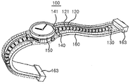
- the flexible device 100 is implemented in the form of a smart watch that can be worn on the wrist of a wearable computer.
- the present invention is not limited to the above embodiments.
- FIG. 3A is a view for explaining the detailed configuration of the flexible device 100
- FIG. 3B is an enlarged view showing a part of a circle represented by a two-dot chain line in FIG. 3A.
- a through hole 121 may be formed in each of the moving members 120, and a through hole 121 of each moving member 120 may be penetrated by the wire 110.
- FIG. Accordingly, each of the movable members 120 may be present in a line on the wire 110.
- the diameter of the through hole 121 may be set to be larger than the diameter of the wire 110, assuming that both the wire 110 and the through hole 121 are formed in a cylindrical shape. In this case, each moving member 120 can move freely on the wire 110 along the longitudinal direction of the wire 110, but can not move beyond the adjacent moving member 120.
- the stopper 130 provided at one end 111 of the wire 110 is fixed to one end 111 of the wire 110 so that the moving member 120 passes through one end 111 of the wire 110, (110).
- the stopper 130 may have a size that can not pass through the through hole 121 of the movable member 120.
- the blocking member 140 can prevent the moving member 120 from being detached from the wire 110 through the other end 112 of the wire 110.
- the stopper 130 and the blocking member 140 may perform similar functions at one end 111 and the other end 112 of the wire 110, respectively.
- the stopper 130 and the blocking member 140 may be structurally different from each other in terms of their function.
- the blocking member 140 is not attached to the other end 112 of the wire 110, unlike the stopper 130 Lt; / RTI >
- the barrier member 140 may be formed with a passage 141 through which the other end 112 of the wire 110 can freely pass.
- the passage 141 may be formed to a size such that the wire 110 can pass but not the moving member 120 so that the blocking member 140 moves the moving member 120 away from the wire 110 .
- the blocking member 140 may be formed in a polyhedral shape fixed to a predetermined position of the main body 150, but is not limited thereto.
- the blocking member 140 may be fixed to the main body 150 of the flexible device 100 to be described later.
- the passage 141 may be formed at a predetermined position of the blocking member 140 in the form of a through hole. When the blocking member 140 is formed in a polyhedral shape, the entrance of the passage 141 is connected to one of two mutually facing surfaces of the surface of the blocking member 140, Respectively.
- a position adjusting member 113 may be provided at the other end 112 of the wire 110.
- the position adjusting member 113 can prevent the other end 112 of the wire 110 from moving across the passage 141 of the blocking member 140. [ Accordingly, the wire 110 can be prevented from separating from the blocking member 140.
- the position adjusting member 113 can be coupled to the operating member 153. [ The user of the flexible device 100 moves the position adjusting member 113 by operating the operating member 153 so that the other end 112 of the wire 110 is moved away from the blocking member 140 110). More specific details of the operating member 153 and the position adjusting member 113 will be described with reference to FIGS. 5A to 5C, which will be described later.
- the operating member 153 can be formed in a circular ring shape so as to be easily mounted on the main body 150 of the flexible device 100.
- the shape of the operating member 153 shown in Fig. 3A is merely an example, it is also possible to implement the operating member 153 with a ring of a polygonal shape rather than a circular shape. Furthermore, it is also possible to implement the operating member 153 in a form other than the ring shape, which is suitable for moving the position adjusting member 113.
- the flexible device 100 may further include a main body 150, a fixing member 163, and a lower body 162. Assuming that the flexible device 100 is implemented in the form of a smart watch as described above, the main body 150 may be a part of the user's wrist which is in contact with the back of the user, .
- the lower body 162 may be formed of a flexible material such as leather so as to have an elongated shape.
- the main body 150 may be coupled to one end of the lower body 162 and the fixing member 163 may be coupled to the other end.
- the fixing member 163 is preferably formed of a hard material, but is not limited thereto. 3A, the lower body 162 and the fixing member 163 may be provided on both sides of the body 150, respectively.
- the blocking member 140 and the operating member 153 may be mounted on the main body 150 in a state where the main body 150, the fixing member 163 and the lower body 162 are coupled to each other as described above.
- a plurality of moving members 120 penetrating through the wire 110 and a stopper 130 coupled to one end 111 of the wire 110 may be placed on the lower body 162.
- a part of the wire 110 is allowed to pass through the passage 141 of the blocking member 140 so that the moving member 120 and the stopper 130 are disposed on one side with the passage 141 therebetween,
- the other end 112 of the wire 110 may be positioned.
- a structure composed of the wire 110, the movable member 120, and the stopper 130 (hereinafter referred to as " flexible frame " for convenience) One for each body 162.
- the blocking member 140 and the passageway 141 may also be provided, one for each flexible frame.
- the upper body 161 of the same material as the lower body 162 can cover the lower body 162 while the flexible frame is placed on the lower body 162 as described above.
- One end of the upper body 161 may be coupled to the main body 150 and the other end of the upper body 161 may be coupled to the fixing member 163, respectively. Accordingly, the upper body 161 and the lower body 162 may form a single body 160 having a space for mounting the flexible frame therein, as shown in FIG. 3C.
- the assembled flexible device 100 includes a main body 150, a flat display 151, a body 160 and a fixing member 163 provided on the front surface of the main body 150 And may be configured to be exposed to the outside. Accordingly, the wire 110, the moving member 120, the stopper 130, and the blocking member 140 are present inside the main body 150 or the body 160, and can not be seen from the outside.
- the operation member 153 may be provided so that all or a part of the operation member 153 can be exposed to the outside so that the user of the flexible device 100 can manually operate it. However, when the operation member 153 is automatically operated through a small motor (not shown) It may be arranged not to be exposed.
- the flexible device 100 of FIG. 3C can be worn on the wrist of a user by having a wristwatch or a smart watch shape, which is generally common.
- a flexible flexible display 170 is additionally attached to the surface of the body 160, more precisely the surface of the upper body 161, which is exposed to the outside when the user wears the flexible device 100 on the wrist .
- the flexible display 170 may be used for supplementing the flat display 151 provided in the main body 150. When the main body 150 is not provided with the flat display 151, . Exemplary operations that the flexible display 170 can perform in conjunction with other components of the flexible device 100 will be described later.
- the flexible display 170 can be implemented in a variety of ways from a functional or structural perspective.
- the flexible display 170 may include a touch input function.
- the flexible display 170 may be embodied as a flexible touch film on which a specific menu is printed.
- the implementation of the flexible device 100 not including the body 160 of FIG. 3C is also possible as shown in FIG. 3D.
- components such as the wire 110 and the movable member 120 may be exposed to the outside.
- the stopper 130 may be integrated with the fixing member 163 according to FIG. 3D.
- the movable member 120 may have a structure capable of supporting the flexible display 170 as shown in FIG. 3D.
- the flexible display 170 of FIGS. 3A and 3C is mounted on the flexible body 160, so that it can be bent together with the body 160 basically. However, depending on the actions of the wire 110, the moving member 120, the stopper 130, and the blocking member 140 included in the flexible device 100, the warping of the flexible display 170 may be suppressed.
- the principle of controlling the possibility of warping is described in detail with reference to FIGS. 2A and 2B, but will be described in detail with reference to FIGS. 4A and 4B.
- FIGS. 4A and 4B are diagrams for explaining the bending possibility control of a flexible device according to an embodiment of the present invention.
- the distance between the stopper 130 and the blocking member 140 is longer than the sum of the lengths of the through holes 121 of each of the moving members 120.
- the body 110 can be bent by the space and the body 160 for mounting the wire 110 therein and the flexible display 170 mounted on the surface of the body 160 are also flexible, And can be bent in a direction deviating from the longitudinal direction of the body (160).
- the wire 110 may be formed so that the length of the passage 141 formed in the blocking member 140 is added to the sum of the lengths of the through holes 121 of each of the moving members 120 It is required to have a long length.
- each of the movable members 120 can be formed in close contact with the adjacent movable member 120 to form the integrated support body 122.
- one end of the supporting body 122 is held in the stopper 130 and the other end is kept in tight contact with the blocking member 140, 130 and the blocking member 140 can not be bent while maintaining a linear shape. Accordingly, the body 160 and the flexible display 170 can be maintained in a non-warped state.
- the curvature of the flexible display 170 can be adjusted by a simple method of adjusting the distance between the stopper 130 and the blocking member 140 by pulling or loosening the wire 110.
- the system also has advantages of simple structure and easy implementation.
- 5A to 5C are views for explaining a structure for performing a function of pulling or loosening a wire in a flexible device according to an embodiment of the present invention.
- the position regulating member 113 can be fixedly coupled to the other end 112 of the wire 110. As shown in FIG. Accordingly, it is possible to pull the wire 110 in the direction of the main body 150 by pulling the position adjusting member 113 away from the blocking member 140.
- the position regulating member 113 may have a size that can not pass through the passage 141 of the blocking member 140. This prevents the movable member 120 from moving toward the other end 112 of the wire 110 by preventing the other end 112 of the wire 110 from moving to the space inside the body 160 through the passage 141 It is possible to prevent the wire 110 from being deviated.
- the position regulating member 113 can move along a predetermined second path 142 starting from the passage 141 of the blocking member 140.
- the second path 142 is preferably provided in the main body 150. 5A, the movement of the position adjusting member 113 may be guided by a guide 152 provided in the main body 150 and having an arc shape. In this case, the second path 142 may be a path in contact with the outer wall of the guide 152.
- the flexible device 100 may further include an operation member 153 for moving the position adjusting member 113 on the second path 142.
- the operating member 153 may be formed in a circular ring shape so that the position adjusting member 113 can move in the second path 142 having an arc shape along the shape of the guide 152.
- the position adjusting member 113 since the position adjusting member 113 can be attached to the operating member 153, by the rotational movement of the operating member 153 placed on the second path 142, the position adjusting member 113 may also be moved on the second path 142.
- All or a part of the operating member 153 may be exposed to the outside of the main body 150.
- the user of the flexible device 100 can control the pulling degree of the wire 110 by rotating the operating member 153 by using the portion exposed to the outside of the operating member 153, Can be controlled.
- the flexible device 100 may further include a latch 154.
- the pawl 154 is fixed to the position adjusting member 113 at a position on the second path 142 where the other end 112 of the wire 110 is placed with the wire 110 pulled up to the main body 150 .
- the latch 154 is located at a predetermined position on the second path 142.
- the latch 154 prevents the position adjustment member 113 from passing over the latch 154 through movement in the direction of approaching the passage 141 of the blocking member 140 on the second path 142,
- the control member 113 can perform the function of passing the passage through the latch 154 through the movement in the direction away from the passage 141 on the second passage 142.
- the position adjusting member 113 can not pass through the latch 154 through the movement in the direction of arrow (1) in FIG. 5B, but can pass the latch 154 through the movement in the direction of (2).
- first surface that abuts on the position adjusting member 113 that moves in the direction of the first direction in the surface of the polygonal-shaped latch 154 for performing the above- And may be formed to be perpendicular to the moving direction of the position adjusting member 113 at the moment when the position adjusting member 113 abuts.
- second surface the surface that comes into contact with the position adjusting member 113 that moves in the direction 2 & (Not shown) so as not to be perpendicular to the moving direction of the position adjusting member 113 of FIG.
- the inclination of the second surface may be formed so that the distance between the first surface and the second surface becomes closer as the distance from the center of the main body 150 increases.
- the guide 152 near the position where the latch 154 is installed as described above can be formed with the latch passageway 155 having a size such that the latch 154 can pass therethrough.
- the latch 154 may be positioned over the latch passage 155.
- the position adjusting member 113 moving in the (2) direction reaches the position where the latch 154 exists, the position adjusting member 113 pushes the latch 154 by the inclination formed on the second face, Direction.
- the latch 154 is pushed toward the center of the main body 150 through the latch passage 155 and the position adjusting member 113 can pass through the position where the latch 154 is present.
- the position adjusting member 113 moving in the direction of arrow 1 reaches the position where the latch 154 exists
- the first surface is perpendicular to the moving direction of the position adjusting member 113, unlike the second surface, 154 are not pushed toward the center of the main body 150 and are not pushed in the direction of movement of the position adjusting member 113 due to the guide 152.
- the position adjusting member 113 can not pass through the position where the latch 154 exists.
- the flexible device 100 may further include a push button 156 and an elastic body 157 for operation of the latch 154.
- One end of the push button 156 may contact the latch 154 within a range that does not disturb the movement of the position adjusting member 113 and the other end may be exposed to the outside of the main body 150 to the user of the flexible device 100 Lt; / RTI > Accordingly, the outer wall of the main body 150 may be provided with a hole for allowing the push button 156 to pass therethrough.
- One end of the elastic body 157 may be connected to the one end of the push button 156 and the other end may be connected to the outer wall of the main body 150, respectively.
- the elastic body 157 may be provided in the form of a spring that winds the portion of the push button 156 exposed outside the main body 150. Even if the push button 156 is pushed by the user in the direction of the center of the main body 150, the resilient force of the elastic body 157 releases the push button 156, together with the pawl 154, Will return to its original position before pressing.
- FIG. 5C a description will be given of a method of allowing or suppressing flexing of the flexible display 170 using the operating member 153 and the push button 156.
- FIG. 5C The flexible device 100 in FIG. 5C is in a state in which the flexible display 170 can be bent because the wire 110 is not sufficiently pulled in the direction of the main body 150.
- the operating member 153 may be operated so that the position adjusting member 113 passes the position where the latch 154 is mounted as shown in FIG. 5C.
- the latch 154 which has been pushed toward the center of the main body 150, can return to its original position by the restoring force of the elastic body 157.
- the returning latch 154 may block the position adjusting member 113 from moving the position where the latch 154 is present in the direction of arrow No. 1 in FIG. 5B.
- the wire 110 can be pulled up to the main body 150 as much as possible.
- the flexible display 170 can be naturally maintained in a state where it can not be bent.
- the user presses the push button 156 as shown in (C) of Figure 5C to move the pawl 154 in the direction of the center of the main body 150 .
- the position adjusting member 113 which has been blocked by movement of the latch 154 in the direction of the arrow 1, moves toward the blocking member 140 through the position where the latch 154 is located as shown in (D) Lt; / RTI >
- a space is created between the plurality of moving members 120 penetrated by the wire 110, resulting in a state in which the flexible display 170 can be bent.
- the push button 156 can return to the original position by the restoring force of the elastic body 157 as shown in (E) of FIG.
- FIGS. 6A and 6B are views for explaining an embodiment for restoring a flexible device according to an embodiment of the present invention from a straightened state to a restored state.
- the position adjusting member 113 is fixed by using the latch 154 , It is possible to prevent the flexible display 170 from being bent.
- the push button 156 is pushed to release the pawl 154 from the second path 142, The position adjusting member 113 can be moved toward the passage 141 of the blocking member 140 by using the operating member 153.
- the act of operating the operating member 153 may also be troublesome to the user. Even if the position adjusting member 113 is moved until the position adjusting member 113 is in close contact with the blocking member 140, the wire 110 does not necessarily return to the state before the wire 110 is pulled. This is because the pushing force of the wire 110 at the other end 112 of the wire 110 may not be transmitted to the end 111 of the wire 110 due to the flexibility of the wire 110.
- an elastic member 164 one end of which is connected to the fixing member 163 of the body 160 and the other end of which is connected to the stopper 130, (160). ≪ / RTI > The body 160 and the flexible device 170 can freely bend when an elastic force is not applied to the elastic member 164 as shown in FIG. 6A and the elastic member 164 has the original length.
- the stopper 130 When the wire 110 is pulled toward the main body 150, the distance between the stopper 130 and the fixing member 163 increases. Accordingly, the length of the elastic member 164 also increases, and the stopper 130 receives a force toward the fixing member 163 due to the restoring force of the elastic member 164.
- the stopper 130 does not actually move toward the fixing member 163.
- the pawl 154 can no longer restrict the movement of the position adjustment member 113. Accordingly, the stopper 130, which can not move due to the fixing of the position adjusting member 113, is also automatically moved toward the fixing member 163 by the restoring force of the elastic member 164. As a result, the flexible device 100 And returns to the state shown in FIG. 6A again.
- the flexible device 100 can be bent only by pushing the push button 156 in a state where the wire 110 is pulled to the maximum It can be conveniently returned to its original state.
- 7A to 7D are views for explaining an embodiment for preventing distortion of a flexible device according to an embodiment of the present invention.
- the support member 122 in which the moving members 120 are closely contacted, axis, a warpage may occur in the support 122 as shown in FIG. 7A.
- Such a warpage of the support member 122 may cause a distortion of the flexible display member 170, so a measure for preventing the support member 122 from being warped may be required.
- a method of adding irregularities to each moving member 120 can be considered.
- one of the convex shapes of the adjacent two moving members 120 can be coupled to the other concave shape.
- the blocking member 140 may also have a recessed shape so that the recessed shape of the blocking member 140 is mutually coupled with the iron shape of the moving member 120 adjacent to the blocking member 140.
- the stopper 130 is also provided with a recess or an iron so as to engage with the moving member 120 adjacent to the stopper 130.
- the movable member 120, the stopper 130, and the blocking member 140 are engaged with each other by the concavo-convex shape, so that the distortion of the flexible display 170 can be prevented as a result .
- a flexible second wire 114 is additionally connected to the stopper 130.
- the blocking member 140 may additionally have a second passageway 144 through which the second wire 114 passes.
- the plurality of second moving members 124 having the through holes 125 whose diameters are such that the stopper 130 can not pass through the through holes 125 are passed through the second wires 114, (130) and the blocking member (140).
- Each of the plurality of second moving members 124 can freely move along the second wire 114.
- the second wire 114 and the second moving member 124 may be made of the same material and shape as the wire 110 and the moving member 120, respectively.
- the second moving member 124 passes through the one end 115 of the second wire 114 because the stopper 130 has a size that can not pass through the through hole 125 of the second moving member 124 It is impossible to deviate from the second wire 114. Since the second moving member 124 has such a size that it can not pass through the second passage 144, the second moving member 124 passes through the other end (not shown) of the second wire 114, It is also impossible to deviate from the two wire 114.
- the user can maintain the pulled state of the wire 110 and the second wire 114 in the direction of the main body 150 as much as possible.
- the plurality of movable members 120 form the integrated support 122, and at the same time, a plurality of the second movable members 124 can be integrally formed with the support (not shown).
- two elongated supports of the same shape are formed, they can be more resistant to twisting than when only one support is provided.
- one of the moving members 120 may be formed in a shape different from that of the other moving member 120, as shown in FIG. 7D (A).
- One moving member 120 having such a different shape is referred to as an intermediate member 127 for the sake of convenience.
- the through hole 128 of the intermediate member 127 may be formed in a semicircular shape so that both ends of the through hole 128 are opposed to the blocking member 140 or the main body 150 .
- the outer shape of the intermediate member 127 itself may also be made to have a semicircular shape as shown in FIG. 7D.
- the stopper 130 attached to the blocking member 140 or the main body 150 and the stopper 130 attached to the main body 150 and the intermediate member 160 that changes the extension direction of the wire 110 can be formed by pulling the wire 110 as much as possible in the direction of the main body 150,
- the effect that the two support members 122 are attached to one blocking member 140 as shown in Fig. 7 (B) can be achieved. That is, an effect similar to that of the embodiment of FIG. 7C can be obtained through the embodiment of FIG. 7D.
- the distance between the passage 141 of the shut-off member 140 and the intermediate member 127 is set to be shorter than the distance between the stopper 140 and the intermediate member 127 in a state in which the wire 110 is pulled toward the main body 150 as much as possible, It is required to arrange the shifting member 120 so as to be equal to the distance between the intermediate member 130 and the intermediate member 127.
- FIG. 8A to 8D are views for explaining an embodiment for preventing an excessive bending of a flexible device according to an embodiment of the present invention.
- the moving member 120 can be pulled toward the stopper 130 as shown in FIG. 8A.
- a portion of the wire 110 that is not occupied by the movable member 120 may be sharply folded, which may cause the flexible display 170 to be folded to cause damage to the flexible display 170 Can result.
- a method of adjusting the distance between the moving members 120 moving on the wire 110 may be proposed.
- each moving member 120 is connected to the adjacent moving member 120 through the connecting member 129.
- a connecting member 129 is made of a material which is bent without resistance by a pressing force (compression force) in the longitudinal direction at both ends but does not extend by a force (tensile force) pulling in the longitudinal direction, It can be made of a non-stretched material. Accordingly, the gap between two adjacent moving members 120 can not exceed a predetermined critical gap defined by the length of the coupling member 129 as shown in FIG. 8 (A). On the other hand, as shown in FIG. 8B (B), the gap between the two moving members 120 adjacent to each other due to the flexibility of the connecting member 129 can be made narrower than the critical gap.
- FIG. 8B shows that two connecting members 129 can be used to connect the two adjacent moving members 120.
- the present invention is not limited thereto, so that three or more connecting members 129 may be used It is possible.
- the movable member 120 adjacent to the stopper 130 may be connected to the stopper 130 through the connecting member 129 and the movable member 120 adjacent to the blocking member 140 may be blocked And may be connected to the member 140 through the connecting member 129 as well.
- the degree of bending of the wire 110 may be limited to a certain level by the action of the connecting member 129, as shown in FIG. 8C.
- the flexible display 170 can be prevented from being excessively bent, thereby preventing the flexible display 170 from being damaged.
- FIG. 8C shows another embodiment for preventing excessive flexing of the flexible display 170.
- the connecting member 129 is not necessarily made of a flexible material, but can also be made of a hard material.
- a groove 123 is formed on a side surface of each moving member 120, and a connecting member 129 is inserted into the groove 123.
- the connecting member 129 inserted into the groove 123 formed in one of the two moving members 120 adjacent to each other is attached to the remaining one moving member 120, or the remaining one And can also be inserted into the groove 123 formed in the movable member 120.
- the interval between two adjacent moving members 120 can be adjusted to a predetermined critical interval or less.
- connection member 129 may be formed in a dumbbell-like structure surrounding the wire 110 as shown in FIG. 8C.
- the connecting member 129 can move along the wire 110 while being penetrated by the wire 110.
- the diameter of the central portion of the connecting member 129 may be smaller than the diameter of the inlet of the through hole 121 of the moving member 120.
- the diameter of the both ends of the connecting member 129 may be smaller than the diameter of the through hole 121 of the moving member 120, May be formed larger than the diameter of the inlet of the heat exchanger (121).
- a space enough to accommodate both ends of the connecting member 129 may be formed in the moving member 120.
- the inlet of the through hole 121 facing each other of the two adjacent shifting members 120 can be made to pass by the center portion of one connecting member 129 under the condition as described above.
- One end of each of the opposite ends of the connecting member 129 may be positioned inside one moving member 120 of the adjacent two moving members 120 and the other end may be positioned inside the other moving member 120, respectively.
- the distance between the adjacent two movable members 120 is not limited, but the maximum extendable range can be limited so as not to be greater than the distance between the opposite ends of the connecting member 129.
- a curvature control unit 180 extending in the direction of the stopper 130 may be attached to the blocking member 140 in parallel with the wire 110.
- the curvature adjusting unit 180 may include a plurality of unit members 181 coupled to each other in a row.
- each of the unit members 181 may have a polyhedral shape, and the curvature adjusting unit 180 may be formed in a straight shape so that the two unit members 181
- the shape of the unit member 181 can be adjusted so that the angle? Formed by the plane is less than or equal to a predetermined threshold angle.
- the degree of bending of the curvature adjusting unit 180 can be adjusted to a certain level or less. That is, the curvature of the arc formed by connecting the centers of the unit members 181 can be adjusted so as not to exceed the predetermined critical curvature.
- the curvature adjuster 180 may be mounted inside the body 160 to extend in the longitudinal direction of the body 160 and extend at least from the edge of the flexible display 170 to the farthest corner from the blocking member 140 . According to the operation of the curvature adjuster 180 as described above, the body 160 also does not bend beyond the critical curvature, and damage due to breakage of the flexible display 170 can be prevented.
- FIGS. 9A to 9D are diagrams for explaining an embodiment for achieving the anti-curl effect in the entire area of the flexible device according to the embodiment of the present invention. 8A to 8D that the flexible device 100 may be excessively bent when the wire 110 is not pulled in the direction of the main body 150.
- FIG. 9A since there is a space between the stopper 130 and the fixing member 163 even when the wire 110 is pulled to the maximum extent in the direction of the main body 150, The portion surrounding the space may be bent or folded.
- a curvature-preventing portion 190 made of a hard material is embedded in the body 160 and can be mounted between the stopper 130 and the fixing member 163.
- a structure of the curvature-preventing portion 190 a structure called “ bellows " may be employed in everyday life, but the present invention is not limited thereto.
- the curvature-preventing portion 190 may be constituted by a plurality of bar-shaped frames 191 coupled to each other in a row.
- Two adjacent frames 191 of the frame 191 may be coupled to each other by a joint 192. More specifically, two adjacent frames 191 may be positioned such that a portion of the end portions of the two adjacent frames 191 overlap each other, and the joint 192 may penetrate both of the adjacent two frames 191 in the overlapping region.
- the two frames 191 coupled through the joint 192 can perform rotational motion about the joint 192.
- One end of the anti-curling portion 190 configured as described above may be attached to the fixing member 163 and the other end thereof may be attached to the stopper 130, respectively.
- 9B a total of two curvature preventing portions 190 are shown between the stopper 130 and the fixing member 163, but the present invention is not limited thereto, and therefore, one or more curvature preventing portions 190 may exist.
- FIG. 9A shows the curvature-preventing portion 190 when the wire 110 is not pulled in the direction of the main body 150.
- FIG. 9B shows the folded curled elastic member 190 which is folded is also extended and extended .
- the curvature preventing portion 190 may be formed of a material that surrounds the space between the stopper 130 and the fixing member 163 in the body 160 It is possible to prevent warping or breaking.
- 9C shows another embodiment of the curvature-preventing portion 190.
- the curvature-preventing portion 190 can be anything as long as the distance from one end to the other end can be freely adjusted by an external force. It is also possible that the elastic member 164 described with reference to FIGS. 6A and 6B is mounted between the stopper 130 and the fixing member 163 together with the anti-curling portion 190.
- the non-moving member 193 of Fig. 9D can be considered in addition to the curvature-preventing portion 190.
- the non-moving member 193 may be fixed at a predetermined position in the body 160, and it is preferable that the non-moving member 193 is attached to the fixing member 163 in order to maximize the anti-warping effect.
- the non-moving member 193 may have a through hole 194 penetrated by the wire 110.
- the wire 110 can freely move within the through hole 194, but the moving member 120 can not pass through the through hole 194 due to its size.
- the through hole 194 of the non-moving member 193 may be formed in a semicircular shape. More specifically, both ends of the through hole 194 may be formed to face the blocking member 140 or the main body 150. Therefore, the outer shape of the non-moving member 193 itself can also be made to have a semicircular shape as shown in FIG. 9D.
- a portion of the wire 110 in the body 160 can be divided into two parts with the non-moving member 193 as a boundary.
- the portion between the blocking member 140 and the non-moving member 193 may be referred to as a first portion
- the portion between the non-moving member 193 and the stopper 130 may be referred to as a second portion.
- the movable member 120 may be divided into a first portion and a second portion as shown in Fig. 9D.
- a second stopper 131 separate from the stopper 130 that functions to restrict the movement of the moving member 120 similarly to the stopper 130 is provided on the first portion of the wire 110, And can be fixedly installed at a predetermined position.
- the second stopper 131 may have such a size that it can not pass through the through hole 121 of the moving member 120 and the through hole 194 of the non-moving member 193.
- 9A shows a state in which the wire 110 is not pulled in the direction of the main body 150 in the present embodiment using the non-moving member 193 and the second stopper 131. [ 9A, the wire 110 extending in the direction away from the blocking member 140 passes through the through hole 194 of the non-moving member 193, And reaches the stopper 130 as shown in FIG.
- each moving member 120 in the first part is moved in the direction 2 stopper 131, and each of the moving members 120 of the second portion will be in close contact with the stopper 130 and the non-moving member 193.
- a total of two supports 122 can be produced in parallel, one for each of the first and second portions.
- the lengths of the first portion and the second portion when the wire 110 is pulled in the direction of the main body 150 to the maximum are adjusted appropriately so that the support body 122 can be simultaneously produced in the first portion and the second portion
- the number of the movable members 120 present in each part also needs to be appropriately adjusted.
- FIGS. 10A and 10B are views for explaining another embodiment of a flexible device according to an embodiment of the present invention.
- the support body 122 made of the movable member 120 is formed by pulling the wire 110 in the direction of the main body 150.
- 10A by moving the blocking member 140 in the direction of the stopper 130 without pulling the wire 110, the plurality of moving members 120 are brought into close contact with each other to form the supporting body 122 .
- the flexible display 100 shown in FIG. 10A can basically have the same structure as the flexible display 100 described with reference to FIGS. 3A to 4B. However, when the stopper 130 is located at a predetermined position in the body 160 And the blocking member 140 can be moved or extended from the main body 150 toward the stopper 130. As shown in Fig. Specifically, without the movement of the wire 110, the blocking member 140 can be moved or extended by the operating member 153.
- the stopper 130 may be fixed to the fixing member 163 or may be fixed to the fixing member 163 It may be preferable to be integrally formed.
- FIG. 10B is a view showing a flexible device 100 further including a wire 110 and a rail member 165 surrounding the moving member 120.
- the rail member 165 may be made of a flexible material so as not to interfere with the warping of the wire 110 and the body 160, And can be mounted at a predetermined position.
- the movement of the moving member 120 or the blocking member 140 can be guided by the rail member 165 so that the wire 110 and the moving member 120 move in the direction of extension of the wire 110 It is possible to prevent it from oscillating in a vertical direction.
- a rail member 165 can be applied to the flexible device 100 shown in FIG. 10A as well as the flexible device 100 described with reference to the other drawings.
- the stopper 130 may be guided by the rail member 165, like the moving member 120.
- a space other than the minimum space in which the movable member 120 and the blocking member 140 can move in the space in the body 160 may be the same or similar to the body 160 It is also possible to fill with material.
- an elongated groove may be formed in the inner wall of the body 160, and the moving member 120 and the blocking member 140 may be moved within a range not deviating from the groove.
- FIGS. 11A and 11B are views for explaining an embodiment in which a wire is not used among the flexible devices according to an embodiment of the present invention.
- the flexible device 200 shown in FIGS. 11A and 11B may include a flexible member 210, a movable member 220, a stopper 230, and a blocking member 240.
- the flexible member 210 may have a tube shape having a space 213 therein, and may be freely bent in a direction opposite to the longitudinal direction due to flexibility.
- the flexible member 210 is formed in the shape of a cylinder having a circular cross section, but it is not necessarily limited to this.
- the shape of the inner space 213 of the flexible member 210 and the shape seen from the outside may be different from each other. For example, even if the internal space 213 of the flexible member 210 is cylindrical, the external shape may be a rectangular parallelepiped.
- a plurality of moving members 220 may be positioned in the inner space 213 of the flexible member 210.
- the plurality of moving members 220 may be arranged in a row in the inner space 213 and may move the inner space 213 in the longitudinal direction of the flexible member 210. That is, the inner space 213 may be a path through which the moving member 220 can move.
- the cross section of the movable member 220 can be made to have the same size and shape as the cross section of the internal space 213 of the flexible member 210. In this case, due to the pressure of the air between the adjacent movable members 220, The movement of the member 220 may not be smooth. In order to solve such a problem, each of the moving members 220 may be provided with a through hole 221.
- the through hole 221 is formed in parallel with the moving path of the moving member 220 moving in the inner space 213, so that the air in the inner space 213 can be smoothly flowed.
- the stopper 230 may be provided at one end 211 of the flexible member 210 to prevent the moving member 220 from separating from the inner space 213 of the flexible member 210.
- the stopper 230 formed of a hard material may be attached to one end 211 of the flexible member 210. 11A, the inner space 213 of the flexible member 210 can be prevented from being exposed to the outside through one end 211 of the flexible member 210.
- the blocking member 240 may be provided at the other end 212 of the flexible member 210 and may move or extend toward the inner space 213 of the flexible member 210 or toward the stopper 230. By moving or stretching the blocking member 240, the adjacent moving members 220 of the plurality of moving members 220 can be brought into close contact with each other.
- the plurality of movable members 220 may form a single support 222 and the support 222 may be in close contact with the stopper 230 and the blocking member 240.
- the movable member 220 and the blocking member 240 can be formed of a hard material so that when the supporting member 222 is in close contact with the stopper 230 and the blocking member 240, Can be suppressed. When the blocking member 240 moves away from the stopper 230 and returns to the original position, the flexible member 210 can be bent again.
- the flexible member 210 itself can serve as the body 160 of the flexible display 100 of Figs. 3A-B. Therefore, a flexible display (not shown) may be attached to the surface 214 of the flexible member 210 exposed to the outside.
- the flexible device 200 of FIG. 11A may have a simpler structure than the flexible display 100 of FIGS. 3A through 10B in which the wire 110 and the body 160 exist as separate components.
- the surface 214 of the flexible member 210 may be formed to have a flat shape instead of a curved surface.
- the flexible device 200 of FIG. 11B is in a state in which the adjacent moving members 220 are not in close contact with each other and the flexible member 210 can be bent. In this state, by pulling the flexible member 210, a plurality of movable members 220 can be formed to form one support 222, and as a result, warpage of the flexible member 210 can be suppressed.
- the flexible device 200 according to the embodiment of FIG. 11B is a subject of movement because the flexible member 210, which is relatively easy to manufacture with a relatively large volume as compared with the blocking member 240, Can be advantageous.
- FIGS. 12A to 12C are diagrams for explaining a state transition of a flexible device according to an embodiment of the present invention.
- the flexible device 100 of Figs. 12A to 12C is basically assumed to have the same configuration as that of the flexible device 100 shown in Figs. 3A to 3C.
- the flexible display 170 included in the flexible device 100 of FIGS. 12A to 12C is a flexible display device in which the movable member 120 is integrally formed with the support body 122 and is in close contact with the stopper 130 and the blocking member 140, It is possible to operate differently depending on whether bending of the body 170 is suppressed (or whether bending of the body 160 is suppressed when the flexible display 170 is not mounted on the body 160).
- the flexible display 170 can be operated to be in an ON state only in a state in which warpage is suppressed and in an OFF state in a state in which warpage is not suppressed.
- the type of the function that is activated only when the flexure of the flexible display 170 or the body 160 is suppressed is not limited to the on / off control of the flexible display 170.
- the function to be activated only in a state in which the warp is suppressed may be related to a component other than the flexible display 170 (for example, a display state change of the flat display 151) among the flexible devices 100.
- the flexible device 100 may further include a sensor unit (not shown) for detecting whether or not the flexure of the flexible display 170 is suppressed.
- a sensor unit for detecting whether or not the flexure of the flexible display 170 is suppressed. For example, when the wire 110 is pulled out in the direction of the main body 150, the position adjusting member 113 is positioned at a predetermined position where the position adjusting member 113 is positioned, It is possible to detect whether or not it exists. If the position adjusting member 113 exists at the predetermined position, the sensor unit can determine that the warping of the flexible display 170 is suppressed, and if it does not exist, it can be determined that the warping is not suppressed.
- the flexible device 100 may further include a control unit (not shown) implemented by a computing device such as a microprocessor.
- the control unit may generate a command for driving the flexible display 170 based on the sensing signal generated by the sensor unit and may further generate a command for controlling the flat display 151 Command can also be generated.
- the flexible display 170 can be operated differently depending on whether or not it is curled.
- the specific configuration and operation principle of the sensor unit and the control unit are obvious to those of ordinary skill in the art and will not be described in detail here.
- the flexible display 170 can operate in conjunction with the flat display 151 provided in the main body 150. 12A, in which flexing of the flexible display 170 is not restrained, the flexible display 170 may be in the OFF state so that all the functions or information for the user are displayed on the flat display 151. [ Lt; / RTI > However, in the state where the flexible display 170 is prevented from being warped as shown in FIG. 12A, the flexible display 170 is turned on, so that some of the functions or information provided through the flat display 151 And can be provided through the flexible display 170.
- FIG. 12B is a view for explaining another example of utilization of the flexible display 170.
- FIG. 12B shows a situation in which a text message arrives in a state in which the warpage of the flexible display 170 is not suppressed.
- the flat display 151 may output a notification message to notify that the text message has arrived.
- the flat display 151 displays the contents of the text message A display window may be output.
- the flexible display 170 may be provided with a touch input unit for generating a response message to the text message.
- the condition of suppressing warping of the flexible display 170 when the condition of suppressing warping of the flexible display 170 is satisfied, it is possible to set a predetermined function such as the ON state change of the flexible display 170 or the touch input unit output to be automatically activated.
- the user of the flexible device 100 can use the flexible device 100 more conveniently since the operation for restricting the bending of the flexible display 170 is not required for the activation.
- FIG. 12C is a diagram for explaining another embodiment related to the use of the smart watch type flexible device 100.
- a smart watch type flexible device 100 that can be worn on a user's wrist can have a function as a telephone, particularly as a portable wireless communication terminal capable of wireless communication.
- a screen informing that the phone has arrived at the flat display 151 may be output.
- the user can suppress the bending of the body 160 by rotating the operation member 153, so that the flexible device 100 can be in the same state as the hard device which can not be bent.
- the flexing of the body 160 of the flexible device 100 is suppressed and at the same time the flexible device 100 can initiate the call based on the incoming signal so that the user can make a call with the party have. That is, the user can obtain both of the results of the deformation of the flexible device 100 and the call initiation through one operation of rotation of the operating member 153.
- the main body 150 of the flexible device 100 is provided with a sound output unit 171 such as a speaker and an audio input unit such as a microphone 172 can be mounted. That is, the voice output unit 171 and the voice input unit 172 are spatially separated, so that the voice output unit 171 and the voice input unit 172 can be brought close to the user's ear and mouth, respectively. Accordingly, it is possible for the user to use the flexible device 100 whose warp is suppressed, as a general mobile phone.
- the sound output unit 171 is mounted on the body 160 and the sound input unit 172 is mounted on the main body 150, respectively. It is also possible that both the audio output unit 171 and the audio input unit 172 are mounted on either the main body 150 or the body 160 if the above spatial separation can be achieved.
- the position of the voice output unit 171 and the voice input unit 172 can be determined such that the flexible device 100 is separated from the flexible device 100 by a predetermined distance in a state in which the flexure of the flexible device 100 is suppressed.
- the operation of turning the operation member 153 that is, the operation of suppressing the flexing of the flexible device 100 and the operation of receiving the telephone can be unified, the kind of operation to be integrated with the anti- ≪ / RTI >
- the flexible device 100 when the user depresses the flexing of the flexible device 100 by turning the operating member 153, the flexible device 100 is simultaneously mounted on the body 160 A text input window for sending a reply to a text message can be output to the flexible display 170.
- functions such as the start of a call or the output of a character input window described with reference to Fig. 12C can be made to occur only in a state where the warping of the flexible device 100 is suppressed through the rotation of the operating member 153.
- the body 160 is straightened. This is similar to the situation where the flexing of the flexible device 100 is apparently suppressed. However, The body 160 may be bent, so that the function may not be expressed. With this feature, a malfunction of the flexible device 100 which is not intended by the user can be prevented.
- FIGS. 13A and 13B are views for explaining another embodiment of a flexible device according to an embodiment of the present invention.
- the flexible device 100 according to an exemplary embodiment of the present invention is not necessarily implemented as a smart watch, but may be implemented as a wearable phone as shown in FIGS. 13A and 13B.
- the wire 110, the movable member 120, the stopper 130, and the shielding member 140 can be mounted in the flexible body 160.
- An operation member 153 may be provided on a side surface of the body 160 and the wire 110 may be pulled or pulled by moving the operation member 153.
- the flexible device 170 may be attached to the surface of the body 160 as shown in FIG.
- the upper portion 166 of the body 160 of the flexible device 100 may be in a state in which warpage is always suppressed by a separate rigid member (not shown) provided inside the body 160.
- the lower portion 167 of the body 160 can be adjusted in its bendability by the action of the wire 110, the moving member 120, the stopper 130 and the blocking member 140 mounted therein have.
- the flexible display 170 can operate as a single display with the entire area turned on. With this function, the convenience of the flexible device 100 can be further improved.
- the flexible display 170 can be warped, it is not limited to whether the flexible display 170 is turned on, and various functions may be activated or deactivated depending on whether the flexible display 170 is warped or not. For example, when a text message is received by the flexible device 100, only when the flexible display 170 is switched to a state in which the flexible display 170 can not be bent, a dialog window for responding to the text message received via the flexible device 100, Or the like can be output to the flexible display 170. [
Landscapes
- Engineering & Computer Science (AREA)
- Physics & Mathematics (AREA)
- Theoretical Computer Science (AREA)
- General Physics & Mathematics (AREA)
- General Engineering & Computer Science (AREA)
- Human Computer Interaction (AREA)
- Computer Hardware Design (AREA)
- Nonlinear Science (AREA)
- Signal Processing (AREA)
- Mathematical Physics (AREA)
- Chemical & Material Sciences (AREA)
- Crystallography & Structural Chemistry (AREA)
- Optics & Photonics (AREA)
- Telephone Set Structure (AREA)
- Devices For Indicating Variable Information By Combining Individual Elements (AREA)
Abstract
본 발명의 일 실시예에 따른 고정 가능한 플렉서블 디바이스는, 가요성(可撓性)을 갖는 가요성 부재, 상기 가요성 부재의 길이 방향을 따라 상기 가요성 부재의 일단에서 타단까지 제공되는 경로 상에 일렬로 배열되며, 상기 경로 상에서 이동 가능한 복수의 이동 부재, 상기 가요성 부재의 일단에 제공되어, 상기 이동 부재가 상기 일단을 통하여 상기 경로 밖으로 벗어나는 것을 차단하는 스토퍼 및 상기 이동 부재가 상기 가요성 부재의 타단을 통하여 상기 경로 밖으로 벗어나는 것을 차단하는 차단 부재를 포함하며, 상기 이동 부재 각각이 상기 경로 상에서 인접한 이동 부재와 밀착하여 일체화된 지지체를 형성할 수 있도록, 상기 경로 중 상기 차단 부재와 상기 스토퍼 사이에 존재하는 부분의 길이가 조절될 수 있다.
Description
본 발명은, 플렉서블 디스플레이(flexible display) 등이 장착될 수 있는 가요성의 몸체가, 필요에 따라 자유롭게 구부러질 수 있는 상태가 되도록 하거나 곧게 펴진 채로 고정된 상태가 되도록 할 수 있는, 고정 가능한 플렉서블 디바이스(flexible device)에 관한 발명이다.
최근, 기존의 디스플레이와 달리 자유롭게 휘어지거나 구부러질 수 있는 플렉서블 디스플레이(flexible display)가 각광받고 있다. 플렉서블 디스플레이는 기존의 디스플레이에 널리 사용되어 온 유리 기판 대신 플라스틱 등 휘어질 수 있는 재료로 된 기판을 이용하여 제조되기 때문에 가요성(可撓性)을 갖는다. 이에 따라, 플렉서블 디스플레이는 곡선형의 벽면 등 굴곡을 갖는 곳에도 자연스럽게 설치될 수 있고, 말거나 접음으로써 간편하게 휴대할 수 있는 등의 여러 장점을 갖는다. 특히, 플렉서블 디스플레이가 근래 널리 보급된 웨어러블 컴퓨터(wearable computer)에 적용될 경우, 사람의 신체 형상에 맞춰 자유롭게 변형될 수 있는 플렉서블 디스플레이의 특성에 의해, 웨어러블 컴퓨터의 더욱 편리한 이용이 가능해진다.
하지만, 플렉서블 디스플레이는 그 가요성으로 인해, 전술한 장점과 함께 단점 역시 아울러 갖는다. 가장 문제가 되는 단점 중 하나로는, 작은 외력에도 의도치 않은 변형이 일어날 수 있다는 것을 들 수 있다. 따라서, 터치스크린(touch screen) 방식으로 구현된 플렉서블 디스플레이를 손가락으로 터치하여 조작하고자 하는 사용자는, 경질의 기존 디스플레이를 터치할 때에 비해 불편함을 느낄 수 있다. 이에, 경우에 따라서는 플렉서블 디스플레이의 휘어짐을 억제해야 할 필요가 있을 수 있다.
도 1은 플렉서블 디스플레이의 가요성을 억제하기 위한 종래 기술에 대해 설명하기 위한 도면이다. 도 1에 의하면, 플렉서블 디스플레이(1)는 경질의 테두리(2)에 의해 지지됨으로써 고정성을 가질 수 있다. 이러한 도 1의 방식은 구현이 간편하나, 테두리(2)의 모양대로만 플렉서블 디스플레이(1)의 형상이 유지됨으로써, 플렉서블 디스플레이(1) 본연의 가요성을 지나치게 제약할 수 있다. 즉, 도 1의 방식에 따르면, 플렉서블 디스플레이(1)의 변형의 자유도가 감소되어, 다양한 상황에서 그에 적합한 모양을 취할 수 있는 플렉서블 디스플레이(1)가 갖는 장점이 퇴색될 수 있다.
본 발명이 해결하고자 하는 과제는, 플렉서블 디스플레이를 비롯한 플렉서블 디바이스에 있어서, 디바이스의 휘어짐 가능 여부를 상황에 따라 원하는 대로 간편하게 조절할 수 있는 장치 및 방법에 관한 것이다.
다만, 본 발명이 해결하고자 하는 과제는 이상에서 언급한 것으로 제한되지 않으며, 언급되지 않은 또 다른 해결하고자 하는 과제는 아래의 기재로부터 본 발명이 속하는 통상의 지식을 가진 자에게 명확하게 이해될 수 있을 것이다.
본 발명의 일 실시예에 따른 고정 가능한 플렉서블 디바이스는, 가요성(可撓性)을 갖는 가요성 부재, 상기 가요성 부재의 길이 방향을 따라 상기 가요성 부재의 일단에서 타단까지 제공되는 경로 상에 일렬로 배열되며, 상기 경로 상에서 이동 가능한 복수의 이동 부재, 상기 가요성 부재의 일단에 제공되어, 상기 이동 부재가 상기 일단을 통하여 상기 경로 밖으로 벗어나는 것을 차단하는 스토퍼 및 상기 이동 부재가 상기 가요성 부재의 타단을 통하여 상기 경로 밖으로 벗어나는 것을 차단하는 차단 부재를 포함하며, 상기 이동 부재 각각이 상기 경로 상에서 인접한 이동 부재와 밀착하여 일체화된 지지체를 형성할 수 있도록, 상기 경로 중 상기 차단 부재와 상기 스토퍼 사이에 존재하는 부분의 길이가 조절될 수 있다.
또한, 상기 가요성 부재는, 가요성의 와이어이고, 상기 이동 부재 각각은, 상기 와이어에 의해 관통되는 관통 구멍을 가지며, 상기 와이어를 따라 이동 가능하며, 상기 스토퍼는, 상기 이동 부재 각각의 관통 구멍을 통과할 수 없는 크기로, 상기 와이어의 일단에 제공되며, 상기 차단 부재는, 상기 와이어에 의해 관통되는 통로를 갖되, 상기 이동 부재가 상기 통로를 통하여 상기 와이어의 타단 방향으로 이동하는 것을 차단할 수 있다.
또한, 상기 와이어의 길이는, 상기 이동 부재 각각의 관통 구멍의 길이의 총합에, 상기 통로의 길이를 더한 것보다 길 수 있다.
또한, 상기 지지체가 상기 스토퍼 및 상기 차단 부재에 밀착된 상태에서, 상기 와이어 중 상기 스토퍼와 상기 차단 부재 사이의 부분은 직선 형태를 가질 수 있다.
또한, 상기 플렉서블 디바이스는, 상기 와이어의 타단에 제공되며, 상기 통로를 통과할 수 없는 크기를 갖는 위치 조절 부재를 더 포함할 수 있다.
또한, 상기 위치 조절 부재는, 상기 통로로부터 시작되는 소정의 제 2 경로를 따라 이동함으로써, 상기 와이어 중 상기 스토퍼와 상기 차단 부재 사이의 부분의 길이를 조절할 수 있다.
또한, 상기 위치 조절 부재는, 상기 제 2 경로 상의 소정 위치에 고정되어, 상기 지지체가 상기 스토퍼 및 상기 차단 부재에 밀착된 상태를 유지할 수 있다.
또한, 상기 플렉서블 디바이스는, 상기 제 2 경로 상의 소정 위치에 위치하여, 상기 위치 조절 부재가 상기 제 2 경로 상에서 상기 통로로 접근하는 방향의 움직임을 통해 상기 소정 위치를 지나는 것은 차단하되, 상기 위치 조절 부재가 상기 제 2 경로 상에서 상기 통로로부터 멀어지는 방향의 움직임을 통해 상기 소정 위치를 지나는 것은 차단하지 않는 걸림쇠를 더 포함할 수 있다.
또한, 상기 스토퍼, 상기 차단 부재 및 상기 이동 부재 각각은 요철(凹凸) 형상을 가지며, 상기 요철 형상을 이용하여, 상기 이동 부재 각각은 인접한 이동 부재와 맞물릴 수 있으며, 상기 차단 부재는 상기 이동 부재 중 상기 차단 부재에 인접한 이동 부재와 맞물릴 수 있고, 상기 스토퍼는 상기 이동 부재 중 상기 스토퍼에 인접한 이동 부재와 맞물릴 수 있다.
또한, 상기 플렉서블 디바이스는, 일단이 상기 스토퍼에 부착되는 제 2 와이어 및 상기 제 2 와이어에 의해 관통되되, 상기 스토퍼가 통과할 수 없는 직경을 갖는 관통 구멍을 가지며, 상기 제 2 와이어 상에 일렬로 배열되어 상기 제 2 와이어를 따라 이동 가능한 복수의 제 2 이동 부재를 더 포함하며, 상기 차단 부재는, 상기 제 2 와이어에 의해 관통되는 제 2 통로를 갖되, 상기 제 2 이동 부재가 상기 제 2 통로를 통하여 상기 제 2 와이어의 타단 방향으로 이동하는 것을 차단할 수 있다.
또한, 상기 스토퍼는, 상기 차단 부재에 부착될 수 있다.
또한, 상기 플렉서블 디바이스는, 상기 이동 부재 중 서로 인접한 두 개의 이동 부재 사이의 간격이 소정의 임계 간격을 넘지 않도록, 상기 서로 인접한 두 개의 이동 부재를 서로 연결하는 연결 부재를 더 포함할 수 있다.
또한, 상기 플렉서블 디바이스는, 일단이 상기 차단 부재에 부착되고, 상기 와이어, 상기 이동 부재 및 상기 스토퍼를 내장하며, 상기 차단 부재로부터 멀어지는 방향으로 연장되는, 가요성을 갖는 몸체를 더 포함할 수 있다.
또한, 상기 플렉서블 디바이스는, 상기 차단 부재에 부착되고, 상기 몸체에 내장되어 상기 차단 부재로부터 상기 몸체의 길이 방향으로 연장되며, 상기 몸체가 소정의 임계 곡률을 초과하여 구부러지는 것을 방지하는 곡률 조절부를 더 포함할 수 있다.
또한, 상기 곡률 조절부는, 일렬로 서로 결합된 복수의 단위 부재를 포함하며, 상기 단위 부재 각각의 중심을 연결하여 형성되는 원호가 상기 임계 곡률을 초과하지 않도록 유지될 수 있다.
또한, 상기 몸체는, 상기 몸체의 타단에 마련되는 경질의 고정 부재 및 상기 몸체에 내장되고, 일단이 상기 고정 부재에, 타단이 상기 스토퍼에 각각 부착되는 탄성 부재를 포함하며, 상기 탄성 부재는, 상기 지지체가 상기 스토퍼 및 상기 차단 부재에 밀착된 상태에서, 상기 고정 부재 방향으로의 복원력을 상기 스토퍼에 가할 수 있다.
또한, 상기 몸체는, 상기 몸체의 타단에 마련되는 경질의 고정 부재 및 상기 몸체에 내장되고, 일단이 상기 고정 부재에, 타단이 상기 스토퍼에 각각 부착되며, 상기 몸체가 휘어지는 것을 방지하는 경질의 만곡 방지부를 하나 이상 포함할 수 있다.
또한, 상기 만곡 방지부는, 일렬로 서로 결합된 복수의 막대 형상 프레임을 포함하며, 상기 프레임 중 인접한 두 프레임은, 상기 인접한 두 프레임을 관통하는 조인트를 통해 결합되되, 상기 조인트를 축으로 하여 회전 운동이 가능할 수 있다.
또한, 상기 플렉서블 디바이스는, 상기 몸체 내의 소정 위치에 고정되고, 상기 와이어에 의해 관통되되 상기 이동 부재는 통과할 수 없는 크기를 갖는 관통 구멍을 갖는 비이동 부재 및 상기 와이어 상의 소정 위치에 고정되어 상기 차단 부재와 상기 비이동 부재 사이에 존재하되, 상기 이동 부재의 관통 구멍 및 상기 비이동 부재의 관통 구멍을 통과할 수 없는 크기를 갖는 제 2 스토퍼를 더 포함하며, 상기 복수의 이동 부재 중 일부는 상기 와이어 상에서 상기 차단 부재와 상기 제 2 스토퍼 사이에 존재하고, 나머지는 상기 와이어 상에서 상기 비이동 부재와 상기 스토퍼 사이에 존재할 수 있다.
또한, 상기 비이동 부재의 관통 구멍은, 반원 형태로 형성되되, 상기 관통 구멍의 양 끝이 상기 차단 부재와 대향(對向)하도록 형성될 수 있다.
또한, 상기 스토퍼는 상기 몸체 내부의 임의의 위치에 고정되며, 상기 차단 부재는, 상기 스토퍼 방향으로 이동하거나 신장됨으로써, 상기 지지체가 상기 차단 부재 및 상기 스토퍼에 밀착되도록 할 수 있다.
또한, 상기 플렉서블 디바이스는, 상기 몸체 내부에 장착되어, 상기 이동 부재, 스토퍼 및 상기 차단 부재 중 어느 하나의 움직임을 가이드(guide)하는, 가요성을 갖는 직선형의 레일(rail) 부재를 더 포함할 수 있다.
또한, 상기 몸체의 외면에는, 플렉서블 디스플레이(flexible display)가 부착되며, 상기 플렉서블 디스플레이는, 상기 지지체가 상기 스토퍼 및 상기 차단 부재에 밀착된 상태에서만 온(ON) 상태가 되거나, 기 정해진 기능이 작동할 수 있다.
또한, 상기 지지체가 상기 스토퍼 및 상기 차단 부재에 밀착된 상태에서, 상기 스토퍼와 상기 차단 부재 사이의 거리는 상기 경로의 길이보다 짧을 수 있다.
또한, 상기 가요성 부재는, 내부에 공간을 갖는 튜브(tube) 형상을 갖고, 상기 가요성 부재 내부의 공간은, 상기 이동 부재가 이동 가능한 경로로서 제공되며, 상기 차단 부재는, 상기 스토퍼 방향으로 미는 힘을 상기 이동 부재에 가함으로써, 상기 이동 부재 각각이 상기 지지체를 형성하도록 할 수 있다.
또한, 상기 이동 부재에는, 상기 경로에 평행한 관통 구멍이 형성될 수 있다.
또한, 상기 플렉서블 디바이스는 무선 통화 기능을 가지며, 상기 플렉서블 디바이스는, 통화 요청 수신 시에, 상기 지지체가 상기 스토퍼 및 상기 차단 부재에 밀착된 상태가 되면, 상기 통화 요청에 의한 통화가 가능한 상태로 전환될 수 있다.
또한, 상기 플렉서블 디바이스는, 상기 차단 부재가 마련되는 본체, 상기 통화를 통해 상기 플렉서블 디바이스로 전송되는 음성을 출력하는 음성 출력부 및 상기 통화를 통해 상기 통화 요청을 발신한 통신 단말로 전송될 음성을 입력받는 음성 입력부를 더 포함하며, 상기 음성 출력부와 상기 음성 입력부 중 하나는 상기 본체에, 다른 하나는 상기 몸체에 각각 마련될 수 있다.
본 발명의 일 실시예에 따르면, 가요성 부재에 의해 제공되는 경로에서 이동 가능한 복수의 이동 부재의 이동의 자유도를 조절하는 방식을 통해, 플렉서블 디바이스의 휘어짐 가능 여부를 쉽고 간편한 방식으로 조절할 수 있다. 이와 같은 본 발명의 일 실시예에 따른 플렉서블 디바이스는, 사용자가 간편하게 조작할 수 있다는 장점뿐 아니라, 구조가 간단하여 구현이 쉬우며, 여러 가지 변형예를 가질 수 있어 사용자의 다양한 필요를 만족시킬 수 있다는 장점 역시 아울러 가질 수 있다.
본 발명의 일 실시예에 따른 플렉서블 디바이스는, 기본적으로는 그 가요성에 의해 사람의 손목과 같은 굴곡진 곳에 쉽게 장착될 수 있으면서도, 필요에 따라서는 휘어짐이 억제됨에 따라 종래의 경질 디바이스처럼 활용될 수도 있다. 또한, 본 발명의 일 실시예에 따른 플렉서블 디바이스는, 디바이스 전 영역에 대해 균일한 휘어짐 억제의 효과를 거둘 수 있는 수단, 휘어짐이 억제된 상태에서 디바이스의 뒤틀림(torsion)을 방지할 수 있는 수단, 디바이스가 휘어지는 정도를 일정 수준 이하로 제한할 수 있는 수단 등 다양한 수단을 구비할 수 있으므로, 사용자에게 다양한 응용 및 편의를 제공할 수 있다.
아울러, 본 발명의 일 실시예에 따른 플렉서블 디바이스의 가요성 부재에 장착된 플렉서블 디스플레이는, 가요성 부재의 휘어짐 가능 여부에 따라 다르게 동작하는 것이 가능하다. 이와 같은 다양한 부가 기능들을 통해, 본 발명의 일 실시예에 따른 플렉서블 디바이스의 사용자가 누릴 수 있는 편의성이 더욱 증진될 수 있다.
도 1은 플렉서블 디스플레이의 휘어짐을 억제하기 위한 종래 기술에 대해 설명하기 위한 도면이다.
도 2a 내지 2c는 본 발명의 일 실시예에 따른 플렉서블 디바이스의 기본 개념에 대해 설명하기 위한 도면이다.
도 3a 내지 3d는 본 발명의 일 실시예에 따른 플렉서블 디바이스의 예시적인 구현 형태를 설명하기 위한 도면이다.
도 4a 및 4b는 본 발명의 일 실시예에 따른 플렉서블 디바이스의 휘어짐 가능 여부 조절에 대해 설명하기 위한 도면이다.
도 5a 내지 5c는 본 발명의 일 실시예에 따른 플렉서블 디바이스에서 와이어를 당기거나 푸는 기능을 수행하기 위한 구조를 설명하기 위한 도면이다.
도 6a 및 6b는 본 발명의 일 실시예에 따른 플렉서블 디바이스를, 곧게 펴진 상태로부터 원상 복귀시키기 위한 실시예에 대해 설명하기 위한 도면이다.
도 7a 내지 7d는 본 발명의 일 실시예에 따른 플렉서블 디바이스의 뒤틀림을 방지하기 위한 실시예에 대해 설명하기 위한 도면이다.
도 8a 내지 8d는 본 발명의 일 실시예에 따른 플렉서블 디바이스가 과도하게 꺾이는 것을 방지하기 위한 실시예에 대해 설명하기 위한 도면이다.
도 9a 내지 9d는 본 발명의 일 실시예에 따른 플렉서블 디바이스의 전 영역에서 휘어짐 억제 효과를 달성하기 위한 실시예에 대해 설명하기 위한 도면이다.
도 10a 및 10b는 본 발명의 일 실시예에 따른 플렉서블 디바이스의 또 다른 구현 형태를 설명하기 위한 도면이다.
도 11a 및 11b는 본 발명의 일 실시예에 따른 플렉서블 디바이스 중 와이어가 사용되지 않은 구현 형태를 설명하기 위한 도면이다.
도 12a 내지 12c는 본 발명의 일 실시예에 따른 플렉서블 디바이스의 동작 상태 전환에 대해 설명하기 위한 도면이다.
도 13a 및 13b는 본 발명의 일 실시예에 따른 플렉서블 디바이스의 또 다른 구현 형태를 설명하기 위한 도면이다.
본 발명의 이점 및 특징, 그리고 그것들을 달성하는 방법은 첨부되는 도면과 함께 상세하게 후술되어 있는 실시예들을 참조하면 명확해질 것이다. 그러나 본 발명은 이하에서 개시되는 실시예들에 한정되는 것이 아니라 서로 다른 다양한 형태로 구현될 수 있으며, 단지 본 실시예들은 본 발명의 개시가 완전하도록 하고, 본 발명이 속하는 기술분야에서 통상의 지식을 가진 자에게 발명의 범주를 완전하게 알려주기 위해 제공되는 것이며, 본 발명은 청구항의 범주에 의해 정의될 뿐이다.
본 발명의 실시예들을 설명함에 있어서 공지 기능 또는 구성에 대한 구체적인 설명이 본 발명의 요지를 불필요하게 흐릴 수 있다고 판단되는 경우에는 그 상세한 설명을 생략할 것이다. 그리고 후술되는 용어들은 본 발명의 실시예에서의 기능을 고려하여 정의된 용어들로서 이는 사용자, 운용자의 의도 또는 관례 등에 따라 달라질 수 있다. 그러므로 그 정의는 본 명세서 전반에 걸친 내용을 토대로 내려져야 할 것이다.
도 2a 내지 2c는 본 발명의 일 실시예에 따른 플렉서블 디바이스의 기본 개념에 대해 설명하기 위한 도면이다. 우선 도 2a는 본 발명의 일 실시예에 따른 플렉서블 디바이스(10)의 구성 요소에 대해 설명하기 위한 도면이다. 도 2a의 플렉서블 디바이스(10)는 가요성 부재(11), 복수의 이동 부재(21), 스토퍼(31) 및 차단 부재(41)를 포함하여 구성될 수 있다.
가요성 부재(11)는 소정 방향으로 연장(延長)됨으로써, 막대와 같은 기다란 형상을 가질 수 있다. 이러한 형상을 갖는 가요성 부재(11)는 휘어질 수 있는 재료, 예컨대 금속 와이어(wire), 합성 수지(plastic) 등의 재료로 제작될 수 있다. 이에 따라, 가요성 부재(11)는 가요성을 가짐으로써 외력에 의해 자유롭게 휘어질 수 있다.
이동 부재(21)는 가요성 부재(11)의 길이 방향을 따라 제공되는 경로(12) 상에서 자유롭게 이동할 수 있는 부재일 수 있다. 이와 같은 이동 부재(21)는, 가요성 부재(11)와 달리 외력에 의해 변형되지 않는 경질(硬質)의 재료로 제작되는 것이 바람직하다. 이동 부재(21)가 이동할 수 있는 경로(12)는 기본적으로 가요성 부재(11)의 일단(一端, 13)에서 타단(他端, 14) 사이의 영역에 제공될 수 있으며, 따라서 상기 경로(12)의 길이는 가요성 부재(11)의 길이를 초과할 수 없게 된다. 도 2a 내지 2c에 예시적으로 도시된 바에 의하면, 이동 부재(21)는 가요성 부재(11)에 의해 관통될 수 있으며, 이에 의해 가요성 부재(11)의 길이 방향을 따라 움직일 수 있게 된다.
이와 같은 이동 부재(21)는 경로(12) 상에 복수 개 존재할 수 있다. 상기 경로(12)는 기본적으로 가요성 부재(11)의 길이 방향을 따라 형성된 1차원의 경로이므로, 복수의 이동 부재(21) 각각은 경로(12) 상에 일렬로 배열되어 상기 경로(12) 상에서 1차원적인 운동을 할 수 있다. 다만, 도 2a 내지 2c에서는 편의상 이동 부재(21)를 하나만 도시하였음을 밝혀 둔다.
스토퍼(31)는 가요성 부재(11)의 일단(13)에 제공되어, 이동 부재(21)가 상기 일단(13)을 통하여 경로(12) 밖으로 벗어나는 것을 차단할 수 있다. 차단 부재(41)는 이동 부재(21)가 가요성 부재(11)의 타단(14)을 통하여 경로(12) 밖으로 벗어나는 것을 차단할 수 있다. 즉, 스토퍼(31)와 차단 부재(41)에 의해, 이동 부재(21)는 가요성 부재(11)에 의해 형성된 경로(12)를 벗어나지 않은 상태로, 경로(12)를 따라서만 이동하게 된다. 상기 기능의 원활한 수행을 위해, 스토퍼(31)와 차단 부재(41) 역시 이동 부재(21)와 마찬가지로 경질의 재료로 제작될 수 있으나, 반드시 이에 한정되지는 않는다.
도 2a 내지 2c에서 보는 바와 같이, 스토퍼(31)는 가요성 부재(11)의 일단(13)에 결합된 채로 존재하는 것이 바람직하다. 즉, 가요성 부재(11)의 일단(13)의 움직임은 스토퍼(31)의 움직임에 종속되며, 이로써 상기 일단(13)은 스토퍼(31)에 대해 상대적으로 정지된 상태로 존재할 수 있다. 반면, 차단 부재(41)는 가요성 부재(11)의 타단(14)에 결합되지 않은 채로 존재할 수 있다. 이에 따라, 가요성 부재(11)의 타단(14)의 움직임은 차단 부재(41)의 움직임에 종속되지 않는다. 예컨대, 차단 부재(41)가 정지한 상태에서도 가요성 부재(11)의 타단(14)은 자유롭게 움직일 수 있다.
이하에서는 도 2a 내지 2c를 통해 본 발명의 일 실시예에 따른 플렉서블 디바이스(10)의 기본 동작 원리에 대해 설명하도록 한다. 도 2a의 (A)에 도시된 바와 같은 가요성 부재(11), 이동 부재(21), 스토퍼(31) 및 차단 부재(41)는, 도 2a의 (B)와 같이 서로의 위치 관계가 정해질 수 있다. 도 2a의 (B)와 같은 상태에서, 이동 부재(21)는 스토퍼(31)와 차단 부재(41) 사이에 존재할 수 있다. 이동 부재(21)와 스토퍼(31) 사이에 공간(32)이 존재하거나, 혹은 이동 부재(21)와 차단 부재(41) 사이에 공간(42)이 존재할 경우, 이동 부재(21)는 가요성 부재(11)의 길이 방향으로 형성된 경로(12)를 따라 스토퍼(31)와 차단 부재(41) 사이에서 자유롭게 이동할 수 있다.
도 2a의 (B)와 같은 상태에서, 가요성 부재(11)는 도 2b의 (A) 혹은 (B)와 같이 길이 방향과 어긋나는 방향으로 휘어질 수 있다. 보다 정확히 말하면, 가요성 부재(11) 중 이동 부재(21)가 점유하는 부분이 아닌, 공간(32, 42)이 형성되어 있는 부분에 의해 가요성 부재(11)가 휘어지는 것이 가능하다. 반면, 도 2c와 같이 스토퍼(31)와 차단 부재(41) 사이의 거리가 줄어들게 됨에 따라 이동 부재(21)가 스토퍼(31)와 차단 부재(41) 사이에 밀착되어 움직일 수 없는 상태가 된 경우, 도 2b의 공간(32, 42)이 없어짐에 따라, 가요성 부재(11) 중 스토퍼(31)와 차단 부재(41) 사이의 부분은 휘어질 수 없게 된다.
전술한 바를 통해, 스토퍼(31)와 차단 부재(41) 사이의 거리를 조절함으로써, 가요성 부재(11)의 휘어짐을 가능하게 할 수도 있고, 불가능하게 할 수도 있음을 알 수 있다. 이와 같은 원리를 응용하여, 상기 가요성 부재(11), 복수의 이동 부재(21), 스토퍼(31) 및 차단 부재(41)가 내장된 가요성 외장재의 표면에 플렉서블 디스플레이를 부착할 경우, 상황에 따라 플렉서블 디스플레이의 휘어짐의 가부(可否)를 편리하게 조절하는 것이 가능할 것이다.
도 3a 내지 3d는 본 발명의 일 실시예에 따른 플렉서블 디바이스의 예시적인 구현 형태를 설명하기 위한 도면이다. 도 3a 내지 3d에서는 플렉서블 디바이스(100)가 웨어러블 컴퓨터 중 사람의 손목에 착용될 수 있는 스마트워치(smart watch) 형태로 구현되었음을 가정하고 설명하도록 하겠으나, 이는 설명의 편의를 위한 예시일 뿐, 도 3a 내지 3d에 의해 본 발명의 사상이 제한적으로 해석되는 것은 아니다.
도 3a 내지 3d의 플렉서블 디바이스(100)는, 도 2a 내지 2c를 통해 설명한 본 발명의 기본 개념을 따르므로, 가요성 부재로서의 와이어(110), 이동 부재(120), 스토퍼(130) 및 차단 부재(140)를 포함할 수 있다. 도 3a는 플렉서블 디바이스(100)의 세부 구성을 설명하기 위한 도면이며, 도 3b는 도 3a의 2점 쇄선으로 표현된 원 안의 부분을 확대하여 나타낸 세부 도면이다.
도 3a 및 3b에 의하면, 이동 부재(120) 각각에는 관통 구멍(121)이 형성될 수 있으며, 각 이동 부재(120)의 관통 구멍(121)은 와이어(110)에 의해 관통될 수 있다. 이에 따라 각 이동 부재(120)는 와이어(110) 상에서 일렬로 존재할 수 있다. 와이어(110)와 관통 구멍(121)이 모두 원통형으로 형성된다고 가정하면, 관통 구멍(121)의 직경은 와이어(110)의 직경보다 크게 정해질 수 있다. 이 경우, 각 이동 부재(120)는 와이어(110)의 길이 방향을 따라 와이어(110) 상에서 자유롭게 움직일 수 있으나, 인접한 이동 부재(120)를 넘어서 움직일 수는 없다.
와이어(110)의 일단(111)에 제공되는 스토퍼(130)는, 와이어(110)의 일단(111)에 고정되어, 이동 부재(120)가 와이어(110)의 일단(111)을 통과하여 와이어(110)로부터 이탈하는 것을 방지할 수 있다. 이를 위해, 스토퍼(130)는 이동 부재(120)의 관통 구멍(121)을 통과할 수 없는 크기를 가질 수 있다.
차단 부재(140)는 이동 부재(120)가 와이어(110)의 타단(112)을 통과하여 와이어(110)로부터 이탈하는 것을 방지할 수 있다. 즉, 스토퍼(130)와 차단 부재(140)는 서로 유사한 기능을 와이어(110)의 일단(111)과 타단(112)에서 각각 수행할 수 있다. 단, 기능상으로 서로 유사한 스토퍼(130)와 차단 부재(140)는 구조상으로는 서로 상이할 수 있는데, 차단 부재(140)는 스토퍼(130)와 달리 와이어(110)의 타단(112)에 부착되지 않은 상태로 존재할 수 있다. 또한, 차단 부재(140)에는 와이어(110)의 타단(112)이 자유롭게 관통할 수 있는 통로(141)가 형성될 수 있다. 상기 통로(141)는 와이어(110)는 통과시킬 수 있지만 이동 부재(120)는 통과시키지 않는 크기로 형성될 수 있으며, 이로써 차단 부재(140)는 이동 부재(120)가 와이어(110)로부터 이탈하는 것을 막을 수 있다.
이와 같은 차단 부재(140)는 본체(150)의 소정 위치에 고정된 다면체 형태로 형성될 수 있으나, 반드시 이와 같은 형상에 한정되는 것은 아니다. 차단 부재(140)는 후술할 플렉서블 디바이스(100)의 본체(150)에 장착되어 고정될 수 있다. 통로(141)는 차단 부재(140)의 소정 위치에 관통 구멍 형태로 형성될 수 있다. 차단 부재(140)가 다면체 형태로 형성될 경우, 차단 부재(140)의 면 중 서로 대향(對向)하는 두 면 중 하나에 통로(141)의 입구가, 나머지 하나에 통로(141)의 출구가 각각 형성될 수 있다.
와이어(110)의 타단(112)에는 위치 조절 부재(113)가 제공될 수 있다. 위치 조절 부재(113)는 와이어(110)의 타단(112)이 차단 부재(140)의 통로(141)를 가로질러 이동하는 것을 막을 수 있다. 이에 따라, 와이어(110)가 차단 부재(140)로부터 이탈하는 것이 방지될 수 있다.
위치 조절 부재(113)는 조작 부재(153)에 결합될 수 있다. 플렉서블 디바이스(100)의 사용자는 조작 부재(153)를 조작하여 위치 조절 부재(113)를 이동시키는 방식을 이용하여, 와이어(110)의 타단(112)이 차단 부재(140)로부터 멀어지도록 와이어(110)를 당길 수 있다. 조작 부재(153)와 위치 조절 부재(113)에 대한 보다 구체적인 사항에 대해서는 후술할 도 5a 내지 5c를 참조하여 살펴보도록 한다.
조작 부재(153)는, 플렉서블 디바이스(100) 본체(150)에 용이하게 장착될 수 있도록, 원형의 고리(ring) 형태로 형성될 수 있음을 볼 수 있다. 물론 도 3a에 도시된 조작 부재(153)의 형상은 하나의 예시에 불과하므로, 원형이 아닌 다각형 형상의 고리로 조작 부재(153)를 구현하는 것도 가능하다. 더 나아가, 위치 조절 부재(113)를 이동시키기에 적합한, 고리 형태 외의 다른 형태로 조작 부재(153)가 구현되는 것 역시 가능하다.
다음으로는 플렉서블 디바이스(100)의 전체적인 구조에 대해 설명하도록 한다. 플렉서블 디바이스(100)는 본체(150), 고정 부재(163) 및 하부 몸체(162)를 더 포함할 수 있다. 전술한 바와 같이 플렉서블 디바이스(100)가 스마트워치 형태로 구현되었음을 가정할 때, 본체(150)는 사용자의 손목 중 손등과 맞닿은 부분에 위치하여 사용자의 주된 조작 대상이 되는 경질의 부분이 될 수 있다.
하부 몸체(162)는 기다란 형태를 갖도록, 가죽(leather)과 같은 가요성의 재료로 형성될 수 있다. 하부 몸체(162)의 일단에는 본체(150)가 결합될 수 있고, 타단에는 고정 부재(163)가 결합될 수 있다. 고정 부재(163)는 경질의 재료로 형성되는 것이 바람직하나, 반드시 이에 한정되는 것은 아니다. 도 3a에서 볼 수 있는 바와 같이, 하부 몸체(162)와 고정 부재(163)는 본체(150) 양쪽에 각각 하나씩 마련될 수 있다.
상기 본체(150), 고정 부재(163) 및 하부 몸체(162)가 전술한 바와 같이 상호 결합된 상태에서, 차단 부재(140)와 조작 부재(153)가 본체(150)에 장착될 수 있다. 그리고 와이어(110)와, 와이어에 의해 관통된 복수의 이동 부재(120)와, 와이어(110)의 일단(111)에 결합한 스토퍼(130)가 하부 몸체(162) 상에 놓일 수 있다. 이 때, 와이어(110)의 일부가 차단 부재(140)의 통로(141)를 관통하도록 함으로써, 통로(141)를 사이에 두고 한 쪽에는 이동 부재(120) 및 스토퍼(130)가, 다른 쪽에는 와이어(110)의 타단(112)이 각각 위치하도록 할 수 있다.
한편, 와이어(110), 이동 부재(120) 및 스토퍼(130)로 이루어진 구조물(이하에서는 편의상 "가요성 프레임(flexible frame)"라 칭함)은, 도 3a에서 볼 수 있는 바와 같이, 하나의 하부 몸체(162)당 하나씩 마련될 수 있다. 따라서, 차단 부재(140) 및 통로(141) 역시 각각의 가요성 프레임에 하나씩 마련될 수 있다.
전술한 바와 같이 가요성 프레임이 하부 몸체(162)에 놓인 상태에서, 하부 몸체(162)와 같은 재질의 상부 몸체(161)가 하부 몸체(162)를 덮을 수 있다. 물론 상부 몸체(161)는 하부 몸체(162) 하나당 하나씩 마련될 수 있으며, 각 상부 몸체(161)의 일단은 본체(150)에, 타단은 고정 부재(163)에 각각 결합될 수 있다. 이에 따라, 상부 몸체(161)와 하부 몸체(162)는, 도 3c에서와 같이 내부에 가요성 프레임의 실장을 위한 공간을 갖는 하나의 몸체(160)를 형성할 수 있다.
도 3c에서 볼 수 있는 바와 같이, 조립이 완료된 플렉서블 디바이스(100)는, 본체(150), 본체(150)의 전면부에 마련된 평면 디스플레이(151), 몸체(160) 및 고정 부재(163)만이 외부에 드러나도록 구성될 수 있다. 이에 의하면, 와이어(110), 이동 부재(120), 스토퍼(130) 및 차단 부재(140)는 본체(150) 혹은 몸체(160) 내부에 존재하게 되어, 외부에서는 보이지 않게 될 수 있다. 조작 부재(153)는 플렉서블 디바이스(100)의 사용자가 수동으로 조작할 수 있도록 전부 혹은 일부가 외부에 드러나도록 마련될 수 있지만, 소형 모터(미도시) 등을 통해 자동으로 조작될 경우 외부로 전혀 드러나지 않도록 마련될 수도 있다. 도 3c의 플렉서블 디바이스(100)는 일반적으로 흔히 볼 수 있는 손목시계 혹은 스마트워치 형태를 갖게 됨으로써, 사용자의 손목에 착용될 수 있다.
몸체(160)의 표면, 보다 정확히 말하면 사용자가 플렉서블 디바이스(100)를 손목에 착용했을 때 바깥으로 드러나게 되는 상부 몸체(161)의 표면에는, 휘어질 수 있는 플렉서블 디스플레이(170)가 추가로 부착될 수 있다. 이러한 플렉서블 디스플레이(170)는 본체(150)에 마련된 평면 디스플레이(151)를 보완하는 용도로 사용될 수도 있고, 본체(150)에 평면 디스플레이(151)가 마련되지 않을 경우에는 메인(main) 디스플레이의 역할을 할 수도 있다. 플렉서블 디스플레이(170)가 플렉서블 디바이스(100)의 다른 구성 요소와 연동되어 수행할 수 있는 예시적인 동작에 대해서는 후술하도록 한다. 플렉서블 디스플레이(170)는 기능적 혹은 구조적 관점에서 다양한 방법으로 구현될 수 있다. 예컨대, 플렉서블 디스플레이(170)는 터치 입력 기능을 포함할 수 있다. 또한, 플렉서블 디스플레이(170)는 특정 메뉴가 인쇄된 플렉서블 터치 필름으로 구현될 수도 있다.
한편, 도 3a 내지 3c의 실시예와는 달리, 도 3d에서 보는 바와 같이 도 3c의 몸체(160)를 포함하지 않는 플렉서블 디바이스(100)의 구현 역시 가능하다. 이 경우, 와이어(110) 및 이동 부재(120) 등의 구성 요소들이 외부로 노출될 수 있다. 도 3c에 도시된 바와는 달리, 도 3d에 따르면 스토퍼(130)는 고정 부재(163)와 일체화되어 구현될 수도 있다. 또한, 이동 부재(120)는 도 3d에 도시된 바와 같이 플렉서블 디스플레이(170)를 지지할 수 있는 구조를 가질 수 있다.
도 3a 및 3c의 플렉서블 디스플레이(170)는 가요성을 갖는 몸체(160)에 장착되므로, 기본적으로는 몸체(160)와 함께 휘어질 수 있다. 하지만 플렉서블 디바이스(100)에 포함된 와이어(110), 이동 부재(120), 스토퍼(130) 및 차단 부재(140)의 작용에 따라, 플렉서블 디스플레이(170)의 휘어짐이 억제될 수도 있다. 이처럼 휘어짐의 가능 여부를 조절할 수 있는 원리에 대해서는 도 2a 내지 2c를 통해 설명한 바 있으나, 도 4a 및 4b를 참조하여 아래에서 보다 구체적으로 설명하도록 한다.
도 4a 및 4b는 본 발명의 일 실시예에 따른 플렉서블 디바이스의 휘어짐 가능 여부 조절에 대해 설명하기 위한 도면이다. 도 4a에서의 플렉서블 디바이스(100)는, 스토퍼(130)와 차단 부재(140) 사이의 거리가 이동 부재(120) 각각의 관통 구멍(121)의 길이의 총합보다 길다. 이에 따라, 인접한 이동 부재(120) 사이에는 공간이 존재하게 된다. 상기 공간에 의해 와이어(110)가 휘어질 수 있으며, 와이어(110)를 내부에 실장하는 몸체(160)와, 몸체(160)의 표면에 장착된 플렉서블 디스플레이(170) 역시 가요성을 가지므로, 몸체(160)의 길이 방향과 어긋나는 방향으로 휘어질 수 있다. 전술한 바와 같은 상태의 구현을 위해, 와이어(110)는 이동 부재(120) 각각의 관통 구멍(121)의 길이의 총합에, 차단 부재(140)에 형성된 통로(141)의 길이를 더한 것보다 긴 길이를 가질 것이 요구된다.
이 때, 와이어(110)가 본체(150) 방향으로 당겨지면, 인접한 이동 부재(120) 사이의 공간은 점차 줄어들게 된다. 스토퍼(130)와 차단 부재(140) 사이의 거리가 이동 부재(120) 각각의 관통 구멍(121)의 길이의 총합과 같아질 정도로 가까워지면, 인접한 이동 부재(120) 사이의 공간은 모두 사라지게 된다. 이에 따라, 도 4b에서 보는 바와 같이 이동 부재(120) 각각은, 인접한 이동 부재(120)와 밀착함으로써 일체화된 지지체(122)를 형성할 수 있다. 이와 같이 와이어(110)가 당겨진 상태를 계속 유지하면, 지지체(122)의 일단이 스토퍼(130)에, 타단이 차단 부재(140)에 각각 밀착된 상태로 유지되므로, 와이어(110) 중 스토퍼(130)와 차단 부재(140) 사이의 부분은 직선 형태를 유지한 채로 휘어질 수 없게 된다. 이에 따라, 몸체(160) 및 플렉서블 디스플레이(170) 역시 휘어지지 않는 상태를 유지할 수 있다.
정리하면, 와이어(110)를 당기거나 풀어서 스토퍼(130)와 차단 부재(140) 간의 거리를 조절하는 간단한 방식을 통해, 플렉서블 디스플레이(170)의 휘어짐을 조절할 수 있다. 상기 방식은 조작이 편리하다는 장점뿐 아니라, 구조가 간단하여 구현이 쉽다는 장점 역시 아울러 가질 수 있다.
도 5a 내지 5c는 본 발명의 일 실시예에 따른 플렉서블 디바이스에서 와이어를 당기거나 푸는 기능을 수행하기 위한 구조를 설명하기 위한 도면이다. 도 5a에서 볼 수 있는 바와 같이, 위치 조절 부재(113)는 와이어(110)의 타단(112)에 고정되어 결합될 수 있다. 이에 따라, 위치 조절 부재(113)를 차단 부재(140)와 멀어지도록 당김으로써 와이어(110)를 본체(150) 방향으로 당기는 것이 가능하다. 또한, 위치 조절 부재(113)는 차단 부재(140)의 통로(141)를 통과할 수 없는 크기를 가질 수 있다. 이에 따라, 와이어(110)의 타단(112)이 통로(141)를 거쳐 몸체(160) 내부의 공간으로 이동하는 것을 막음으로써, 이동 부재(120)가 와이어(110)의 타단(112)을 거쳐 와이어(110)로부터 이탈해 버리는 것을 방지할 수도 있다.
위치 조절 부재(113)는 차단 부재(140)의 통로(141)로부터 시작되는 소정의 제 2 경로(142)를 따라 이동할 수 있다. 도 5a의 플렉서블 디바이스(100)에 따르면, 상기 제 2 경로(142)는 본체(150) 내에 마련되는 것이 바람직하다. 도 5a를 참조하면, 위치 조절 부재(113)의 움직임은, 본체(150) 내에 마련되며 원호(圓弧, arc) 형상을 갖는 가이드(152)에 의해 가이드(guide)될 수 있다. 이 경우, 제 2 경로(142)는 가이드(152)의 외벽에 접하는 경로가 될 수 있다.
도 5a에 의하면, 플렉서블 디바이스(100)는 위치 조절 부재(113)를 제 2 경로(142) 상에서 이동시키기 위한 조작 부재(153)를 더 포함할 수 있다. 위치 조절 부재(113)가 가이드(152)의 형상을 따라 원호 형태를 갖는 제 2 경로(142)에서 움직일 수 있도록, 조작 부재(153)는 원형의 고리 형태로 형성될 수 있다. 도 5a에서 볼 수 있는 바와 같이, 위치 조절 부재(113)는 조작 부재(153)에 부착될 수 있으므로, 제 2 경로(142) 위에 놓인 조작 부재(153)의 회전 운동에 의해, 위치 조절 부재(113) 역시 제 2 경로(142) 상에서 움직일 수 있다.
조작 부재(153)의 전부 혹은 일부는 본체(150) 바깥의 외부에 노출될 수 있다. 플렉서블 디바이스(100)의 사용자는 조작 부재(153)의 외부에 노출된 부분을 이용하여 조작 부재(153)를 회전시켜 와이어(110)의 당겨진 정도를 조절함으로써, 몸체(160) 및 플렉서블 디스플레이(170)의 휘어짐의 가부를 조절할 수 있다.
한편, 와이어(110)가 본체(150) 쪽으로 최대로 당겨짐으로써, 몸체(160) 및 플렉서블 디스플레이(170)의 휘어짐이 억제된 상태를 유지해야 할 필요가 있을 수 있다. 이를 위해, 플렉서블 디바이스(100)는 걸림쇠(154)를 더 포함할 수 있다. 걸림쇠(154)는, 와이어(110)가 본체(150) 쪽으로 최대로 당겨진 상태에서 와이어(110)의 타단(112)이 놓이게 되는 제 2 경로(142) 상의 위치에 위치 조절 부재(113)를 고정시킬 수 있다.
도 5b를 살펴보면, 걸림쇠(154)가 제 2 경로(142) 상의 소정 위치에 존재함을 알 수 있다. 상기 걸림쇠(154)는, 위치 조절 부재(113)가 제 2 경로(142) 상에서 차단 부재(140)의 통로(141)로 접근하는 방향의 움직임을 통해 걸림쇠(154)를 지나는 것은 차단하지만, 위치 조절 부재(113)가 제 2 경로(142) 상에서 통로(141)로부터 멀어지는 방향의 움직임을 통해 걸림쇠(154)를 지나는 것은 통과시키는 기능을 수행할 수 있다. 즉, 위치 조절 부재(113)는 도 5b의 ①번 방향의 움직임을 통해서는 걸림쇠(154)를 지나갈 수 없지만, ②번 방향의 움직임을 통해서는 걸림쇠(154)를 지나갈 수 있다.
전술한 기능의 수행을 위해, 다면체 형태를 갖는 걸림쇠(154)의 면(面) 중 ①번 방향으로 움직이는 위치 조절 부재(113)와 맞닿게 되는 면(이하 "제 1 면"으로 칭함)은, 위치 조절 부재(113)와 맞닿는 순간의 위치 조절 부재(113)의 이동 방향과 수직하도록 형성될 수 있다. 이에 반해, 걸림쇠(154)의 면(面) 중 ②번 방향으로 움직이는 위치 조절 부재(113)와 맞닿게 되는 면(이하 "제 2 면"으로 칭함)은, 위치 조절 부재(113)와 맞닿는 순간의 위치 조절 부재(113)의 이동 방향과 수직하지 않도록, 경사(傾斜)지게 형성될 수 있다. 구체적으로, 제 2 면의 경사는, 본체(150)의 중심으로부터 멀어질수록 제 1 면과 제 2 면 사이의 거리가 가까워지도록 형성될 수 있다.
전술한 바와 같은 걸림쇠(154)가 설치되는 위치 근처의 가이드(152)에는, 걸림쇠(154)가 통과할 수 있을 정도의 크기를 갖는 걸림쇠 통로(155)가 형성될 수 있다. 이 때, 걸림쇠(154)는 상기 걸림쇠 통로(155)에 걸쳐진 채로 위치할 수 있다. 그러면, ②번 방향으로 움직이는 위치 조절 부재(113)가 걸림쇠(154)가 존재하는 위치에 다다를 경우, 제 2 면에 형성된 경사에 의해 위치 조절 부재(113)는 걸림쇠(154)를 밀면서 계속 ②번 방향으로 움직이게 된다. 이에 따라 걸림쇠(154)는 걸림쇠 통로(155)를 통해 본체(150)의 중심 방향으로 밀려나게 되며, 위치 조절 부재(113)는 걸림쇠(154)가 존재하던 위치를 통과할 수 있게 된다.
반면, ①번 방향으로 움직이는 위치 조절 부재(113)가 걸림쇠(154)가 존재하는 위치에 다다를 경우, 제 1 면은 제 2 면과 달리 위치 조절 부재(113)의 이동 방향과 수직하므로, 걸림쇠(154)는 본체(150)의 중심 방향으로 밀려나지 않게 되며, 가이드(152)로 인해 위치 조절 부재(113)의 이동 방향으로도 밀려나지 않게 된다. 따라서, 위치 조절 부재(113)는 걸림쇠(154)가 존재하는 위치를 통과할 수 없게 된다.
한편, 플렉서블 디바이스(100)는, 걸림쇠(154)의 조작을 위해, 푸시 버튼(push button, 156) 및 탄성체(157)를 더 포함할 수 있다. 푸시 버튼(156)의 일단은 위치 조절 부재(113)의 움직임을 방해하지 않는 범위 내에서 걸림쇠(154)에 접촉할 수 있으며, 타단은 본체(150) 밖으로 노출되어 플렉서블 디바이스(100)의 사용자에 의해 조작될 수 있다. 따라서, 본체(150)의 외벽에는 푸시 버튼(156)의 통과를 위한 구멍이 형성될 수 있다.
탄성체(157)의 일단은 푸시 버튼(156)의 상기 일단에, 타단은 본체(150)의 외벽에 각각 연결될 수 있다. 예컨대, 탄성체(157)는 푸시 버튼(156) 중 본체(150) 밖으로 노출된 부분을 휘감는 용수철의 형태로 제공될 수 있다. 푸시 버튼(156)이 사용자에 의해 본체(150)의 중심 방향으로 눌린다 해도, 사용자가 누르던 힘을 풀면 탄성체(157)의 복원력에 의해, 푸시 버튼(156)은 걸림쇠(154)와 함께 사용자가 누르기 전의 본래 위치로 복귀할 것이다.
이하에서는 도 5c를 참조하여, 상기 조작 부재(153) 및 푸시 버튼(156)을 이용하여 플렉서블 디스플레이(170)의 휘어짐을 허용하거나 억제하는 방법을 설명하도록 한다. 도 5c의 (A)에서의 플렉서블 디바이스(100)는, 와이어(110)가 본체(150) 방향으로 충분히 당겨지지 않아 플렉서블 디스플레이(170)가 휘어질 수 있는 상태에 있다.
이 때 조작 부재(153)를 동작시켜, 도 5c의 (B)와 같이 위치 조절 부재(113)가 걸림쇠(154)가 장착된 위치를 지나치도록 할 수 있다. 위치 조절 부재(113)가 상기 위치를 지나치면, 본체(150)의 중심 방향으로 밀려나 있던 걸림쇠(154)는 탄성체(157)의 복원력에 의해 본래 위치로 복귀할 수 있다. 복귀한 걸림쇠(154)는, 걸림쇠(154)가 존재하는 위치를 도 5b의 ①번 방향으로 움직이는 위치 조절 부재(113)가 통과하는 것을 차단할 수 있다. 이에 따라, 와이어(110)가 본체(150) 쪽으로 최대한 당겨진 상태가 유지될 수 있으며, 결과적으로는 플렉서블 디스플레이(170)가 휘어질 수 없는 상태가 자연스럽게 유지될 수 있다.
만일 사용자가 플렉서블 디스플레이(170)가 다시 휘어질 수 있게 되기를 원하는 경우, 사용자는 도 5c의 (C)와 같이 푸시 버튼(156)을 눌러 걸림쇠(154)를 본체(150)의 중심 방향으로 이동시킬 수 있다. 그러면, 걸림쇠(154)에 의해 ①번 방향으로의 움직임이 막혀 있던 위치 조절 부재(113)가, 도 5c의 (D)와 같이 걸림쇠(154)가 있던 위치를 지나 차단 부재(140) 쪽으로 이동하는 것이 가능해진다. 이에 따라 와이어(110)에 의해 관통된 복수의 이동 부재(120) 사이에 공간이 생기게 되고, 결과적으로는 플렉서블 디스플레이(170)가 휘어질 수 있는 상태가 된다. 한편, 사용자가 푸시 버튼(156)을 누르던 힘을 풀면, 도 5c의 (E)에서 보는 바와 같이 푸시 버튼(156)이 탄성체(157)의 복원력에 의해 원래 위치로 복귀할 수 있다.
지금까지 도 5a 내지 5c를 참조하여, 조작 부재(153)와 걸림쇠(154) 등을 이용하여 와이어(110)를 기계적으로 당기거나 푸는 동작에 대해 설명하였으나, 와이어(110)를 당기거나 푸는 방식은 반드시 이에 한정되는 것은 아니다. 예컨대, 사용자는 조작 부재(153)를 자신의 힘으로 직접 돌리는 대신, 본체(150)에 내장된 소형 모터(미도시)를 조작함으로써 와이어(110)를 당기거나 푸는 것도 가능하다. 이 때, 사용자는 본체(150)에 마련된 조작 버튼(미도시) 혹은 평면 디스플레이(151)에 출력된 메뉴를 조작함으로써 모터의 동작을 제어할 수 있다.
도 6a 및 6b는 본 발명의 일 실시예에 따른 플렉서블 디바이스를, 곧게 펴진 상태로부터 원상 복귀시키기 위한 실시예에 대해 설명하기 위한 도면이다. 도 5a 내지 5c를 참조하여 설명한 바와 같이, 조작 부재(153)를 이용하여 와이어(110)를 본체(150) 방향으로 최대한 당긴 후, 걸림쇠(154)를 이용하여 위치 조절 부재(113)를 고정시킴으로써, 플렉서블 디스플레이(170)가 휘어질 수 없도록 하는 것이 가능하다. 이 때, 플렉서블 디스플레이(170)가 다시 휘어질 수 있도록 하기 위해 와이어(110)가 최대로 당겨진 상태를 해제하고자 할 경우에는, 푸시 버튼(156)을 눌러 걸림쇠(154)가 제 2 경로(142)를 벗어나도록 한 후, 조작 부재(153)를 이용하여 위치 조절 부재(113)를 차단 부재(140)의 통로(141) 쪽으로 이동시킬 수 있다.
하지만, 조작 부재(153)를 조작하는 행위 자체도 사용자 입장에서는 번거롭게 느껴질 수 있다. 또한, 위치 조절 부재(113)가 차단 부재(140)와 밀착할 때까지 위치 조절 부재(113)를 움직인다고 해도, 반드시 와이어(110)가 당겨지기 전의 상태로 복귀하는 것은 아니다. 이는 와이어(110)의 타단(112)에서 와이어(110)를 미는 힘이 와이어(110)의 가요성으로 인해 와이어(110)의 일단(111)에 온전히 전달되지 않을 수 있기 때문이다.
전술한 바와 같은 문제를 해결하기 위해, 도 6a에서 볼 수 있는 바와 같이 일단이 몸체(160)의 고정 부재(163)에 연결되고, 타단이 스토퍼(130)에 연결되는 탄성 부재(164)가 몸체(160)에 추가로 포함될 수 있다. 도 6a와 같이 탄성 부재(164)에 외력이 가해지지 않아 탄성 부재(164)가 본래의 길이를 갖고 있을 때에는, 몸체(160) 및 플렉서블 디바이스(170)가 자유롭게 휘어질 수 있다.
와이어(110)가 본체(150) 쪽으로 당겨질 경우, 스토퍼(130)와 고정 부재(163) 사이의 거리는 증가하게 된다. 이에 따라 탄성 부재(164)의 길이 역시 증가하며, 스토퍼(130)는 탄성 부재(164)의 복원력에 의해 고정 부재(163) 방향으로의 힘을 받게 된다. 도 6b와 같이 와이어(110)가 본체(150) 방향으로 최대로 당겨짐에 따라 와이어(110), 몸체(160) 및 플렉서블 디스플레이(170)가 곧게 펴졌을 때, 스토퍼(130)에 가해지는 힘은 최대가 될 것이다. 하지만 위치 조절 부재(113)가 걸림쇠(154)에 의해 고정됨에 따라, 스토퍼(130)가 실제로 고정 부재(163) 쪽으로 이동하지는 않는다.
다만, 플렉서블 디스플레이(170)가 다시 휘어질 수 있도록 하기 위해 푸시 버튼(156)을 누르면, 걸림쇠(154)가 더 이상 위치 조절 부재(113)의 움직임을 제약할 수 없게 된다. 이에 따라, 위치 조절 부재(113)의 고정으로 인해 움직일 수 없던 스토퍼(130) 역시 탄성 부재(164)의 복원력에 의해 자동으로 고정 부재(163) 쪽으로 이동하게 되며, 결과적으로 플렉서블 디바이스(100)는 도 6a와 같은 상태로 다시 돌아가게 된다.
전술한 바와 같이 탄성 부재(164)를 이용한 도 6a 및 6b의 실시예에 따르면, 와이어(110)가 최대로 당겨진 상태에서 푸시 버튼(156)을 누르는 것만으로 플렉서블 디바이스(100)를 휘어질 수 있는 원래 상태로 편리하게 복귀시킬 수 있다.
이하에서는 플렉서블 디바이스(100)의 이용에 편의를 더하기 위한, 다양한 추가 실시예들에 대해 살펴보도록 한다. 도 7a 내지 7d는 본 발명의 일 실시예에 따른 플렉서블 디바이스의 뒤틀림을 방지하기 위한 실시예에 대해 설명하기 위한 도면이다. 와이어(110)가 본체(150)방향으로 최대한 당겨져 플렉서블 디스플레이(170)가 휘어질 수 없는 상태라 하더라도, 각 이동 부재(120)가 서로 밀착되어 형성된 지지체(122)에 와이어(110)를 축(axis)으로 하는 돌림힘(torque)이 가해질 경우, 도 7a와 같이 지지체(122)에 뒤틀림이 발생할 수 있다. 이와 같은 지지체(122)의 뒤틀림은 플렉서블 디스플레이(170)의 뒤틀림을 야기할 수 있기 때문에, 지지체(122)의 뒤틀림을 막기 위한 방책이 필요할 수 있다.
이하에서는 상기 방책의 예시에 대해 도 7b 내지 7d를 참조하여 설명하도록 한다. 우선, 도 7b와 같이 각 이동 부재(120)에 요철(凹凸)을 부가하는 방법을 생각할 수 있다. 이 경우, 인접한 두 이동 부재(120) 중 하나의 철(凸) 형상이 나머지 하나의 요(凹) 형상에 결합할 수 있다. 또한, 차단 부재(140)에도 요 형상을 부가하여, 차단 부재(140)의 요 형상이 차단 부재(140)에 인접한 이동 부재(120)의 철 형상과 상호 결합하도록 할 수 있다. 물론, 차단 부재(140)에 철 형상을 부가하고, 차단 부재(140)의 철 형상이 차단 부재(140)에 인접한 이동 부재(120)의 요 형상과 상호 결합하도록 하는 것도 가능하다. 또한, 스토퍼(130)에도 요 형상 혹은 철 형상을 부가하여, 스토퍼(130)에 인접한 이동 부재(120)와 맞물리도록 하는 것이 가능하다. 이와 같은 도 7b의 실시예에 따르면, 요철 형상에 의해 각 이동 부재(120), 스토퍼(130) 및 차단 부재(140)가 서로 맞물림으로써, 결과적으로 플렉서블 디스플레이(170)의 뒤틀림이 방지될 수 있다.
다음으로 도 7c와 같이, 와이어(110)와, 와이어(110)에 꿰어진 복수의 이동 부재(120)로 이루어진 구조물을, 서로 평행하게 두 개 이상 배치하는 방법을 생각할 수 있다. 도 7c를 보면, 와이어(110) 외에도 가요성의 제 2 와이어(114)가 스토퍼(130)에 추가로 연결되어 있음을 볼 수 있다. 차단 부재(140)는 제 2 와이어(114)에 의해 관통되는 제 2 통로(144)를 추가로 가질 수 있다. 또한, 스토퍼(130)가 통과할 수 없는 직경을 갖는 관통 구멍(125)을 갖는 복수의 제 2 이동 부재(124)는, 제 2 와이어(114)에 의해 관통 구멍(125)이 관통된 채로 스토퍼(130)와 차단 부재(140) 사이에 일렬로 배열될 수 있다. 이와 같은 복수의 제 2 이동 부재(124) 각각은 제 2 와이어(114)를 따라 자유롭게 움직일 수 있다. 이와 같은 제 2 와이어(114) 및 제 2 이동 부재(124)는, 와이어(110) 및 이동 부재(120)와 각각 같은 재료 및 형상으로 제작될 수 있다.
스토퍼(130)는 제 2 이동 부재(124)의 관통 구멍(125)을 통과할 수 없는 크기를 가지므로, 제 2 이동 부재(124)는 제 2 와이어(114)의 일단(115)을 통과하여 제 2 와이어(114)를 이탈하는 것이 불가능하다. 또한, 제 2 이동 부재(124)는 제 2 통로(144)를 통과할 수 없는 크기를 가지므로, 제 2 이동 부재(124)가 제 2 와이어(114)의 타단(미도시)을 통과하여 제 2 와이어(114)를 이탈하는 것 역시 불가능하다.
전술한 바와 같은 상태에서 플렉서블 디스플레이(170)가 휘어지지 않도록 하기 위해, 사용자는 와이어(110)와 제 2 와이어(114)가 함께 본체(150) 방향으로 최대한 당겨진 상태를 유지할 수 있다. 그러면 복수의 이동 부재(120)가 일체화된 지지체(122)를 형성하게 되며, 이와 동시에 복수의 제 2 이동 부재(124)가 일체화된 지지체(미도시)를 형성할 수 있다. 즉, 동일한 형상의 기다란 지지체가 두 개 형성되므로, 지지체가 하나만 있을 때에 비해 뒤틀림에 강해질 수 있다.
이에 더하여, 도 7d와 같이 스토퍼(130)를 차단 부재(140) 혹은 본체(150)에 부착하는 방법을 생각할 수도 있다. 도 7d의 실시예를 위해, 도 7d의 (A)와 같이 이동 부재(120) 중 하나를 다른 이동 부재(120)와 다른 형상으로 제작할 수 있다. 이와 같이 다른 형상으로 제작된 하나의 이동 부재(120)를 편의상 중간 부재(127)라 칭하도록 한다. 중간 부재(127)의 관통 구멍(128)은 반원 형태로 형성될 수 있으며, 보다 구체적으로는 관통 구멍(128)의 양 끝이 차단 부재(140) 혹은 본체(150)와 대향(對向)하도록 형성될 수 있다. 이를 위해, 중간 부재(127) 자체의 외형도 도 7d와 같이 반원 형태를 갖도록 제작될 수 있다.
도 7d의 실시예에서 와이어(110)를 본체(150) 방향으로 최대한 당기면, 차단 부재(140) 혹은 본체(150)에 부착된 스토퍼(130)와, 와이어(110)의 연장 방향을 바꾸는 중간 부재(127)의 존재에 의해, 도 7d의 (B)와 같이 하나의 차단 부재(140)에 두 개의 지지체(122)가 부착되어 있는 것과 같은 효과가 달성될 수 있다. 즉, 도 7d의 실시예를 통해서도 도 7c의 실시예와 유사한 효과를 얻을 수 있다. 한편, 도 7d의 실시예가 의도한 대로 동작하기 위해서는, 와이어(110)를 본체(150) 쪽으로 최대한 당긴 상태에서, 차단 부재(140)의 통로(141)와 중간 부재(127) 사이의 거리가 스토퍼(130)와 중간 부재(127) 사이의 거리와 같게 되도록 이동 부재(120)를 배치할 것이 요구된다.
도 8a 내지 8d는 본 발명의 일 실시예에 따른 플렉서블 디바이스가 과도하게 꺾이는 것을 방지하기 위한 실시예에 대해 설명하기 위한 도면이다. 와이어(110)가 몸체(150) 방향으로 최대한 당겨지지 않은 상태에서는, 도 8a와 같이 이동 부재(120)가 스토퍼(130) 쪽으로 쏠릴 수 있다. 이러한 상황에서는 와이어(110) 중 이동 부재(120)에 의해 점유되지 않은 부분이 급격히 꺾이는 상황을 유발할 수 있고, 이는 결국 플렉서블 디스플레이(170)가 접힘(folded)으로써 플렉서블 디스플레이(170)의 손상이 유발되는 결과를 야기할 수 있다. 이러한 문제를 해결하기 위해, 본 발명의 일 실시예에 의하면 와이어(110) 상에서 이동하는 이동 부재(120) 간의 간격을 조절하는 방법이 제안될 수 있다.
도 8b를 참조하면, 연결 부재(129)를 통하여 각 이동 부재(120)가 인접한 이동 부재(120)와 연결되어 있음을 볼 수 있다. 이와 같은 연결 부재(129)는, 양 끝에서 길이 방향으로 미는 힘(압축력)에 의해서는 저항 없이 휘어지나, 길이 방향으로 당기는 힘(인장력)에 의해서는 늘어나지 않는 재료, 즉 가요성을 가지나 길이가 늘어나지는 않는 재료로 제작될 수 있다. 이에 따라, 서로 인접한 두 이동 부재(120) 사이의 간격은 도 8b의 (A)처럼 연결 부재(129)의 길이에 의해 정해지는 소정의 임계 간격을 넘을 수 없게 된다. 이에 반해, 도 8b의 (B)처럼 연결 부재(129)의 가요성에 의해 서로 인접한 두 이동 부재(120) 사이의 간격이 상기 임계 간격보다 좁아지는 것은 얼마든지 가능하다.
한편, 도 8b는 인접한 두 이동 부재(120)를 연결하는 데에 두 개의 연결 부재(129)가 사용될 수 있음을 나타내고 있으나, 반드시 이에 한정되는 것은 아니므로, 세 개 이상의 연결 부재(129)가 사용될 수도 있다. 또한, 이동 부재(120) 중 스토퍼(130)에 인접한 이동 부재(120)는 스토퍼(130)와도 연결 부재(129)를 통해 연결될 수 있으며, 차단 부재(140)에 인접한 이동 부재(120)는 차단 부재(140)와도 연결 부재(129)를 통해 연결될 수 있다.
도 8b의 실시예에 의하면, 도 8b의 (C)에서 볼 수 있는 바와 같이 연결 부재(129)의 작용에 의해 와이어(110)가 휘어지는 정도가 일정 수준 이내로 제한될 수 있다. 이에 따라, 플렉서블 디스플레이(170)가 과도하게 꺾이는 것이 방지될 수 있으므로, 플렉서블 디스플레이(170)의 손상을 막을 수 있다.
도 8c는 플렉서블 디스플레이(170)의 과도한 꺾임을 방지하기 위한 또 다른 실시예를 나타낸다. 도 8c에 의하면, 연결 부재(129)가 반드시 가요성의 재료로만 구현되어야 하는 것은 아니며, 경질의 재료로도 구현될 수 있음을 알 수 있다. 우선 도 8c의 (A)를 보면, 각 이동 부재(120)의 측면에는 홈(123)이 형성되어 있으며, 상기 홈(123)에는 연결 부재(129)가 삽입되어 있음을 볼 수 있다. 이 때, 인접한 두 이동 부재(120) 중 하나의 이동 부재(120)에 형성된 홈(123)에 삽입된 연결 부재(129)는, 나머지 하나의 이동 부재(120)에 부착되거나, 상기 나머지 하나의 이동 부재(120)에 형성된 홈(123)에도 삽입될 수 있다. 이와 같은 구조를 통해, 인접한 두 이동 부재(120) 사이의 간격을 소정의 임계 간격 이하로 조절할 수 있다.
또한, 도 8c의 (B)와 같이 연결 부재(129)가 와이어(110)를 둘러싸는 아령(dumbbell) 형태의 구조로 형성되는 것도 가능하다. 연결 부재(129)는 와이어(110)에 의해 관통된 채로 와이어(110)를 따라 이동할 수 있다. 연결 부재(129)의 중앙부의 직경은 이동 부재(120)의 관통 구멍(121)의 입구의 직경보다 작게 형성될 수 있으며, 연결 부재(129)의 양단부의 직경은 이동 부재(120)의 관통 구멍(121)의 입구의 직경보다 크게 형성될 수 있다. 그리고 이동 부재(120) 내부에는 연결 부재(129) 양단부를 수용할 수 있을 정도의 공간이 형성되도록 할 수 있다.
전술한 바와 같은 조건에서, 인접한 두 이동 부재(120)의 서로 마주보는 관통 구멍(121) 입구가 하나의 연결 부재(129)의 중앙부에 의해 통과되도록 할 수 있다. 그리고 상기 연결 부재(129)의 양단부 중 일단은 상기 인접한 두 이동 부재(120) 중 한 이동 부재(120)의 내부에, 타단은 나머지 한 이동 부재(120)의 내부에 각각 위치하도록 할 수 있다. 그러면, 인접한 두 이동 부재(120) 사이의 간격은 줄어드는 데에는 제한이 없지만, 최대로 늘어날 수 있는 범위는 연결 부재(129)의 양단부 사이의 거리보다 클 수 없도록 제한될 수 있다.
플렉서블 디바이스(170)의 꺾임 방지 기능은 연결 부재(129)를 통한 이동 부재(120) 간의 간격 조절에 의해서만 달성될 수 있는 것은 아니다. 도 8d를 참조하면, 차단 부재(140)에는 스토퍼(130) 방향으로 연장되는 곡률 조절부(180)가 와이어(110)와 나란하게 부착될 수 있다. 상기 곡률 조절부(180)는 일렬로 서로 결합된 복수의 단위 부재(181)를 포함하여 구성될 수 있다.
도 8d의 (A)에서 볼 수 있는 바와 같이, 단위 부재(181) 각각은 다면체 형상을 가질 수 있는데, 곡률 조절부(180)가 직선 형태를 갖도록 곧게 펴진 상태에서 인접한 두 단위 부재(181)의 면이 이루는 각(θ)이 소정의 임계 각도 이하가 되도록 단위 부재(181)의 형상을 조절할 수 있다. 그러면 도 8d의 (B)에서 볼 수 있는 바와 같이, 곡률 조절부(180)의 구부러짐의 정도가 일정 수준 이하로 조절될 수 있다. 즉, 단위 부재(181) 각각의 중심을 연결하여 형성되는 원호의 곡률이 소정의 임계 곡률을 초과하지 않도록 조절될 수 있다.
상기 곡률 조절부(180)는 몸체(160) 내부에 실장되어 몸체(160)의 길이 방향으로 연장될 수 있으며, 최소한 플렉서블 디스플레이(170)의 모서리 중 차단 부재(140)로부터 가장 먼 모서리까지는 연장되는 것이 바람직하다. 전술한 바와 같은 곡률 조절부(180)의 작용에 따라 몸체(160) 역시 상기 임계 곡률을 초과하여 구부러지지 않게 되며, 이에 따라 플렉서블 디스플레이(170)의 꺾임에 의한 손상이 방지될 수 있다.
도 9a 내지 9d는 본 발명의 일 실시예에 따른 플렉서블 디바이스의 전 영역에서 휘어짐 억제 효과를 달성하기 위한 실시예에 대해 설명하기 위한 도면이다. 와이어(110)가 본체(150) 방향으로 당겨지지 않은 상태에서는 플렉서블 디바이스(100)에 과도한 꺾임이 발생할 수 있음을, 위에서 도 8a 내지 8d를 참조하여 살펴보았다. 이와 달리, 도 9a에서 보는 바와 같이, 와이어(110)가 본체(150) 방향으로 최대로 당겨진 상태에서도 스토퍼(130)와 고정 부재(163) 사이에 공간이 존재하게 됨에 따라, 몸체(160) 중 상기 공간을 둘러싸는 부분은 휘어지거나 꺾일 수 있다.
이러한 문제를 방지하기 위해, 경질의 재료로 제작된 만곡 방지부(190)가 몸체(160)에 내장되어 스토퍼(130)와 고정 부재(163) 사이에 장착될 수 있다. 만곡 방지부(190)의 구조로는 일상 생활에서 흔히 "자바라"라고 불리는 구조가 채용될 수 있지만, 반드시 이에 한정되는 것은 아니다.
도 9b를 참조하면, 만곡 방지부(190)는 일렬로 서로 결합된 복수의 막대 형상 프레임(191)에 의해 구성될 수 있다. 상기 프레임(191) 중 인접한 두 프레임(191)은 조인트(192)에 의해 서로 결합될 수 있다. 보다 구체적으로 설명하면, 인접한 두 프레임(191)은 서로의 끝부분의 일부 영역이 겹쳐지도록 위치할 수 있으며, 조인트(192)는 상기 겹쳐진 영역에서 인접한 두 프레임(191) 모두를 관통할 수 있다. 이와 같이 조인트(192)를 통해 결합된 두 프레임(191)은 조인트(192)를 축으로 하는 회전 운동을 할 수 있다.
전술한 바와 같이 구성된 만곡 방지부(190)의 일단은 고정 부재(163)에, 타단은 스토퍼(130)에 각각 부착될 수 있다. 도 9b에서는 만곡 방지부(190)가 스토퍼(130)와 고정 부재(163) 사이에 총 2개 존재하는 것으로 도시되었지만, 반드시 이에 한정되는 것은 아니므로, 한 개 혹은 세 개 이상 존재할 수도 있다.
도 9b의 (A)는 와이어(110)가 본체(150) 방향으로 당겨져 있지 않을 때의 만곡 방지부(190)를 나타낸 것이다. 이 상태에서 도 9b의 (B)와 같이 와이어(110)가 본체(150) 방향으로 당겨져 스토퍼(130)가 고정 부재(163)로부터 멀어지면, 접혀 있던 만곡 방지부(190) 역시 펴지면서 연장될 수 있다. 전술한 바와 같이 만곡 방지부(190)는 경질의 재료로 제작될 수 있으므로, 만곡 방지부(190)는 몸체(160) 중 스토퍼(130)와 고정 부재(163) 사이의 공간을 둘러싸는 부분이 휘어지거나 꺾이는 것을 방지할 수 있다. 도 9c는 만곡 방지부(190)의 또 다른 구현예를 나타낸 것으로, 만곡 방지부(190)는 일단에서 타단까지의 거리가 외력에 의해 자유롭게 조절될 수 있는 것이라면 어떤 것이든 될 수 있다. 또한, 도 6a 및 6b를 통해 설명한 탄성 부재(164)가 만곡 방지부(190)와 함께 스토퍼(130)와 고정 부재(163) 사이에 장착되는 것도 가능하다.
몸체(160)의 전 영역에서 휘어짐 억제 효과를 달성하기 위한 수단으로는, 상기 만곡 방지부(190) 외에도 도 9d의 비이동 부재(193)를 생각할 수 있다. 비이동 부재(193)는 몸체(160) 내의 소정 위치에 고정될 수 있는데, 휘어짐 억제 효과의 극대화를 위해서는 고정 부재(163)에 부착되는 것이 바람직할 것이다.
비이동 부재(193)는 와이어(110)에 의해 관통되는 관통 구멍(194)을 가질 수 있다. 와이어(110)는 관통 구멍(194) 내에서 자유롭게 움직일 수 있지만, 이동 부재(120)는 그 크기로 인해 관통 구멍(194)을 통과할 수 없다. 도 7d를 참조하여 위에서 설명한 중간 부재(127)와 유사하게, 비이동 부재(193)의 관통 구멍(194)은 반원 형태로 형성될 수 있다. 보다 구체적으로는, 관통 구멍(194)의 양 끝은 차단 부재(140) 혹은 본체(150)와 대향하도록 형성될 수 있다. 따라서, 비이동 부재(193) 자체의 외형도 도 9d와 같이 반원 형태를 갖도록 제작될 수 있다.
와이어(110) 중 몸체(160) 내의 부분은 비이동 부재(193)를 경계로 하여 두 부분으로 나뉠 수 있다. 이 때, 차단 부재(140)와 비이동 부재(193) 사이의 부분을 제 1 부분, 비이동 부재(193)와 스토퍼(130) 사이의 부분을 제 2 부분으로 칭할 수 있다. 이동 부재(120)는 도 9d에서 볼 수 있는 바와 같이 제 1 부분과 제 2 부분에 나뉘어 존재할 수 있다. 한편, 스토퍼(130)와 유사하게 이동 부재(120)의 이동을 제한하는 역할을 수행하는, 스토퍼(130)와는 별개의 제 2 스토퍼(131)가, 와이어(110) 상의 상기 제 1 부분에 속하는 소정 위치에 고정되어 설치될 수 있다. 상기 제 2 스토퍼(131)는 이동 부재(120)의 관통 구멍(121) 및 비이동 부재(193)의 관통 구멍(194)을 통과할 수 없는 크기를 가질 수 있다.
도 9d의 (A)는 비이동 부재(193) 및 제 2 스토퍼(131)를 활용한 본 실시예에서, 와이어(110)가 본체(150) 방향으로 당겨지지 않은 상태를 도시한 것이다. 도 9d의 (A)에 의하면, 차단 부재(140)로부터 멀어지는 방향으로 연장되던 와이어(110)가, 비이동 부재(193)의 관통 구멍(194)을 통과하며 방향을 바꾸어 다시 차단 부재(140)에 가까워지는 방향으로 연장되며 스토퍼(130)에 다다르는 것을 볼 수 있다.
도 9d의 (A)와 같은 상태에서 와이어(110)를 본체(150) 방향으로 최대한 당기면, 도 9d의 (B)와 같이 제 1 부분의 각 이동 부재(120)는 차단 부재(140)와 제 2 스토퍼(131) 사이에서 서로 밀착되고, 제 2 부분의 각 이동 부재(120)는 스토퍼(130)와 비이동 부재(193) 사이에서 밀착될 것이다. 이로써 제 1 부분과 제 2 부분에 각각 하나씩, 총 두 개의 지지체(122)가 평행하게 생성될 수 있다. 물론, 제 1 부분과 제 2 부분에 지지체(122)가 동시에 생성될 수 있도록, 와이어(110)를 본체(150) 방향으로 최대한 당겼을 때의 제 1 부분 및 제 2 부분의 길이가 적절히 조절될 필요가 있다. 아울러, 각 부분에 존재하는 이동 부재(120)의 개수 역시 적절히 조절될 필요가 있을 것이다.
도 9d의 (B)에 의하면, 몸체(160)의 전 부분이 두 개의 지지체(122) 중 적어도 하나에 의해 지지될 수 있으므로, 몸체(160) 및 플렉서블 디스플레이(170)의 전 부분에 걸쳐 휘어짐 억제의 효과를 얻을 수 있다. 또한, 지지체(122) 두 개가 서로 평행하게 존재하므로, 도 7c 혹은 7d의 실시예와 유사한 원리에 의해 몸체(160) 및 플렉서블 디스플레이(170)의 뒤틀림 역시 방지할 수 있다.
도 10a 및 10b는 본 발명의 일 실시예에 따른 플렉서블 디바이스의 또 다른 구현 형태를 설명하기 위한 도면이다. 도 2a 내지 9d를 참조하여 지금까지 설명한 플렉서블 디바이스(100)에서는, 와이어(110)를 본체(150) 방향으로 당김으로써 이동 부재(120)로 이루어진 지지체(122)를 형성하였다. 이와 달리, 도 10a의 실시예에 의하면, 와이어(110)를 당기지 않고 차단 부재(140)를 스토퍼(130) 방향으로 이동시킴으로써 복수의 이동 부재(120)를 서로 밀착시켜 지지체(122)를 형성할 수 있다.
도 10a의 (A)에 도시된 플렉서블 디스플레이(100)는 기본적으로 도 3a 내지 4b를 참조하여 설명한 플렉서블 디스플레이(100)와 같은 구조를 가질 수 있으나, 스토퍼(130)가 몸체(160) 내의 소정 위치에 고정되어 있다는 것과, 차단 부재(140)가 본체(150)로부터 스토퍼(130)를 향해 이동하거나 연장될 수 있다는 점을 그 특징으로 한다. 구체적으로, 와이어(110)의 움직임 없이, 차단 부재(140)가 조작 부재(153)에 의해 이동하거나 연장될 수 있다. 스토퍼(130)가 고정되는 위치에는 특별한 제약이 없으나, 몸체(160)의 전 영역에 걸쳐 휘어짐 억제의 효과를 달성하기 위해서는 스토퍼(130)가 고정 부재(163)에 부착되거나, 혹은 고정 부재(163)와 일체로 형성되는 것이 바람직할 것이다.
도 10a의 (A)를 보면, 차단 부재(140)와 스토퍼(130) 사이의 거리가 각 이동 부재(120)의 관통 구멍(121)의 길이를 모두 더한 것보다 길기 때문에, 와이어(110)는 몸체(160)와 함께 휘어질 수 있다. 이와 달리, 도 10a의 (B)와 같이 이동 부재(120)가 일체화된 지지체(122)를 형성할 때까지 차단 부재(140)가 스토퍼(130) 방향으로 이동하거나 연장되면, 와이어(110)와 몸체(160)의 휘어짐은 억제될 수 있다. 즉, 플렉서블 디바이스(100)의 사용자는 차단 부재(140)를 스토퍼(130) 쪽으로 미는 간편한 동작만으로 몸체(160)의 휘어짐을 억제할 수 있다. 그리고 몸체(160)가 다시 휘어지도록 하기 위해서는 차단 부재(140)를 반대 방향, 즉 스토퍼(130)로부터 멀어지는 방향으로 이동시키기만 하면 된다. 또한, 도 10a의 실시예에 의하면, 스토퍼(130)가 고정 부재(163)에 충분히 가까울 경우 그 자체만으로도 몸체(160) 및 몸체(160)에 장착된 플렉서블 디스플레이(170)의 과도한 꺾임이 방지될 수 있으므로, 추가적인 부가 구성이 필요치 않다는 장점도 가질 수 있다.
도 10b는 와이어(110) 및 이동 부재(120)를 감싸는 레일(rail) 부재(165)를 더 포함하는 플렉서블 디바이스(100)를 도시한 도면이다. 레일 부재(165)는 와이어(110) 및 몸체(160)의 휘어짐을 방해하지 않기 위해 가요성 재료로 제작될 수 있으며, 도 10b와 같이 이동 부재(120)를 감싸도록 몸체(160) 내의 공간의 소정 위치에 장착될 수 있다. 이동 부재(120) 혹은 차단 부재(140)의 움직임은 레일 부재(165)에 의해 가이드(guide)될 수 있으며, 이에 따라 와이어(110) 및 이동 부재(120)가 와이어(110)의 연장 방향과 수직한 방향으로 요동하는 것을 막을 수 있다.
이와 같은 레일 부재(165)는 도 10a의 플렉서블 디바이스(100)뿐 아니라, 앞에서 다른 도면을 이용하여 설명된 플렉서블 디바이스(100)에 대해서도 적용될 수 있음은 물론이다. 이 때, 스토퍼(130) 역시 이동 부재(120)와 마찬가지로 레일 부재(165)에 의해 가이드될 수 있을 것이다. 또한, 레일 부재(165)를 설치하는 대신, 몸체(160) 내의 공간 중 이동 부재(120) 및 차단 부재(140)가 움직일 수 있는 최소한의 공간을 제외한 나머지 공간을 몸체(160)와 같거나 유사한 재질의 물질로 채우는 것 역시 가능하다. 실시예에 따라서는, 몸체(160)의 내벽에 기다란 홈을 형성하고, 상기 홈을 벗어나지 않는 범위 내에서 이동 부재(120) 및 차단 부재(140)가 움직이도록 할 수도 있을 것이다.
지금까지는 도 3a 내지 10b를 참조하여 와이어(110)에 의해 이동 부재(120)의 이동 경로가 제공되는 실시예에 대해 살펴보았다. 하지만, 본 발명에 의하면 와이어(110)를 사용하지 않은 실시예의 구현 역시 가능하다. 도 11a 및 11b는 본 발명의 일 실시예에 따른 플렉서블 디바이스 중 와이어가 사용되지 않은 구현 형태를 설명하기 위한 도면이다. 도 11a 및 11b에 도시된 플렉서블 디바이스(200)는, 가요성 부재(210), 이동 부재(220), 스토퍼(230) 및 차단 부재(240)를 포함할 수 있다.
도 11a에 의하면, 가요성 부재(210)는 내부에 공간(213)을 갖는 튜브(tube) 형상을 가질 수 있으며, 가요성을 가져 길이 방향과 어긋나는 방향으로 자유롭게 휘어질 수 있다. 도 11a에 의하면, 가요성 부재(210)는 원형의 단면을 갖는 원통의 형태로 형성되어 있지만, 반드시 이에 한정되지는 않는다. 또한, 가요성 부재(210)의 내부 공간(213)의 형상과 외부에서 보이는 형상 역시 서로 다를 수 있다. 예컨대, 가요성 부재(210)의 내부 공간(213)이 원통형이라 하더라도, 외형은 직육면체 형상일 수 있다.
가요성 부재(210)의 내부 공간(213)에는 복수의 이동 부재(220)가 위치할 수 있다. 복수의 이동 부재(220)는 상기 내부 공간(213) 내에서 일렬로 배열될 수 있으며, 내부 공간(213)을 가요성 부재(210)의 길이 방향으로 이동할 수 있다. 즉, 상기 내부 공간(213)은 이동 부재(220)가 이동 가능한 경로가 될 수 있다.
이동 부재(220)의 단면은 가요성 부재(210)의 내부 공간(213)의 단면과 동일한 크기 및 형상을 갖도록 제작될 수 있는데, 이 경우 인접한 이동 부재(220) 사이의 공기의 압력으로 인해 이동 부재(220)의 이동이 원활하지 않을 수 있다. 이러한 문제를 해결하기 위해, 각 이동 부재(220)에는 관통 구멍(221)이 형성될 수 있다. 이러한 관통 구멍(221)은 내부 공간(213)을 이동하는 이동 부재(220)의 이동 경로와 평행하게 형성됨으로써, 내부 공간(213)의 공기의 유동을 원활히 할 수 있다.
스토퍼(230)는 가요성 부재(210)의 일단(211)에 제공되어, 이동 부재(220)가 가요성 부재(210)의 내부 공간(213)을 이탈하는 것을 방지할 수 있다. 바람직한 예로서, 경질의 재료로 형성된 스토퍼(230)는 가요성 부재(210)의 일단(211)에 부착될 수 있다. 이로써, 도 11a에 도시된 바와 같이 가요성 부재(210)의 내부 공간(213)이 가요성 부재(210)의 일단(211)을 통해 외부로 노출되는 것이 방지될 수 있다.
차단 부재(240)는 가요성 부재(210)의 타단(212)에 제공되어, 가요성 부재(210)의 내부 공간(213)을 향해, 즉 스토퍼(230)를 향해 이동하거나 신장될 수 있다. 차단 부재(240)의 상기 이동 혹은 신장에 의해, 복수의 이동 부재(220) 중 인접한 이동 부재(220)끼리는 서로 밀착될 수 있다. 이로써 복수의 이동 부재(220)는 하나의 지지체(222)를 형성할 수 있으며, 상기 지지체(222)는 스토퍼(230) 및 차단 부재(240)에 밀착될 수 있다. 이동 부재(220) 및 차단 부재(240)는 경질의 재료로 형성될 수 있으므로, 지지체(222)가 스토퍼(230) 및 차단 부재(240)에 밀착된 상태에서는, 가요성 부재(210)의 휘어짐이 억제될 수 있다. 차단 부재(240)가 스토퍼(230)로부터 멀어져 원위치로 돌아가면, 가요성 부재(210)는 다시 휘어질 수 있게 된다.
전술한 바와 같은 기능의 달성을 위해서는, 지지체(222)가 스토퍼(230) 및 차단 부재(240)에 밀착된 상태에서의 스토퍼(230)와 차단 부재(240) 사이의 거리, 즉 지지체(222)의 길이가, 가요성 부재(210)의 내부 공간(213)의 길이, 즉 이동 부재(220)가 이동 가능한 경로의 총 길이보다 짧을 것이 요구된다.
가요성 부재(210)는 그 자체로 도 3a 내지 10b의 플렉서블 디스플레이(100)의 몸체(160)의 역할을 할 수 있다. 따라서 외부에 노출된 가요성 부재(210)의 표면(214)에는 플렉서블 디스플레이(미도시)가 부착될 수 있다. 이처럼 도 11a의 플렉서블 디바이스(200)는, 와이어(110)와 몸체(160)가 별도의 구성 요소로서 존재하는 도 3a 내지 10b의 플렉서블 디스플레이(100)에 비해 간단한 구조를 가질 수 있다. 한편, 플렉서블 디스플레이의 용이한 부착 및 사용을 위해, 가요성 부재(210)의 표면(214)은 곡면이 아닌 평면의 형상을 갖도록 형성되는 것도 가능하다.
한편, 지지체(222)의 형성을 위해 차단 부재(240)를 이동시키는 대신, 도 11b의 실시예와 같이 가요성 부재(210)를 이동시키는 것도 가능하다. 도 11b의 (A)의 플렉서블 디바이스(200)는 인접한 이동 부재(220)끼리 서로 밀착해 있지 않아 가요성 부재(210)가 휘어질 수 있는 상태에 있다. 이 상태에서 가요성 부재(210)를 당김으로써 복수의 이동 부재(220)가 하나의 지지체(222)를 형성하도록 할 수 있으며, 그 결과 가요성 부재(210)의 휘어짐이 억제될 수 있다. 도 11b의 실시예에 의한 플렉서블 디바이스(200)는, 차단 부재(240)에 비해 상대적으로 큰 부피로 제작되기 쉬운 가요성 부재(210)가 움직임의 대상이 되기 때문에, 사용자에 의해 보다 용이하게 조작될 수 있다는 장점을 가질 수 있다.
도 12a 내지 12c는 본 발명의 일 실시예에 따른 플렉서블 디바이스의 상태 전환에 대해 설명하기 위한 도면이다. 도 12a 내지 12c의 플렉서블 디바이스(100)는 기본적으로 도 3a 내지 3c에 도시된 플렉서블 디바이스(100)와 동일한 구성을 가짐을 가정하고 설명하도록 한다.
도 12a 내지 12c의 플렉서블 디바이스(100)에 포함된 플렉서블 디스플레이(170)는, 이동 부재(120)가 일체화된 지지체(122)를 형성하여 스토퍼(130) 및 차단 부재(140)에 밀착됨으로써 플렉서블 디스플레이(170)의 휘어짐이 억제되었는지 여부(혹은, 플렉서블 디스플레이(170)가 몸체(160)에 장착되지 않은 경우에는 몸체(160)의 휘어짐이 억제되었는지 여부)에 따라 달리 작동하는 것이 가능하다. 예컨대, 플렉서블 디스플레이(170)는 휘어짐이 억제된 상태에서만 온(ON) 상태가 되고, 휘어짐이 억제되지 않은 상태에서는 오프(OFF) 상태가 되도록 동작할 수 있다.
물론, 플렉서블 디스플레이(170) 혹은 몸체(160)의 휘어짐이 억제된 상태에서만 발동하는 기능의 종류는 상기 플렉서블 디스플레이(170)의 온/오프 제어에 국한되는 것은 아니다. 예컨대, 상기 휘어짐이 억제된 상태에서만 발동하는 기능은, 플렉서블 디바이스(100) 중 플렉서블 디스플레이(170) 외의 다른 구성요소에 관한 것(예컨대, 평면 디스플레이(151)의 표시 상태 변경)도 될 수 있다.
전술한 바와 같은 기능의 구현을 위해, 플렉서블 디바이스(100)는 플렉서블 디스플레이(170)의 휘어짐이 억제되었는지 여부를 감지하기 위한 센서부(미도시)를 더 포함할 수 있다. 예컨대, 센서부는 상기 휘어짐 억제 여부를 감지하기 위하여, 와이어(110)가 본체(150) 방향으로 최대로 당겨졌을 때 위치 조절 부재(113)가 위치하게 되는 소정 위치에 위치 조절 부재(113)가 실제로 존재하는지의 여부를 감지할 수 있다. 상기 소정 위치에 위치 조절 부재(113)가 존재한다면, 센서부는 플렉서블 디스플레이(170)의 휘어짐이 억제된 것으로 판단할 수 있으며, 존재하지 않는다면 휘어짐이 억제되지 않은 것으로 판단할 수 있을 것이다.
한편, 플렉서블 디바이스(100)는 마이크로프로세서(microprocessor)와 같은 연산 장치에 의해 구현되는 제어부(미도시)를 더 포함할 수 있다. 상기 제어부는 상기 센서부에 의해 생성된 감지 신호에 기초하여, 플렉서블 디스플레이(170)를 구동하기 위한 명령을 생성할 수 있으며, 추가로 본체(150)에 구비된 평면 디스플레이(151)를 제어하기 위한 명령도 생성할 수 있다. 상기 센서부와 제어부의 동작에 의해, 플렉서블 디스플레이(170)는 휘어짐 억제 여부에 따라 달리 동작할 수 있다. 이러한 센서부와 제어부의 구체적인 구성 및 동작 원리는 통상의 기술자에게 자명한 것이므로, 여기에서는 더 이상의 자세한 설명은 생략한다.
플렉서블 디스플레이(170)는 본체(150)에 구비된 평면 디스플레이(151)와 연동되어 동작할 수 있다. 예컨대, 플렉서블 디스플레이(170)의 휘어짐이 억제되지 않은 도 12a의 (A)의 상황에서는, 플렉서블 디스플레이(170)는 OFF 상태일 수 있으며, 이에 따라 사용자를 위한 모든 기능 혹은 정보가 평면 디스플레이(151)를 통해 제공된다. 하지만 도 12a의 (B)와 같이 플렉서블 디스플레이(170)의 휘어짐이 억제된 상태에서는, 플렉서블 디스플레이(170)가 ON 상태가 되며, 이에 따라 평면 디스플레이(151)를 통해 제공되었던 기능 혹은 정보의 일부가 플렉서블 디스플레이(170)를 통해 제공될 수 있다.
도 12a의 예에 의하면, (A)의 상황에서는 플렉서블 디스플레이(170)가 OFF 상태이므로 평면 디스플레이(151)에 표시창(158)과 문자 입력을 위한 터치 입력부(159)가 모두 출력되어 있는 것을 볼 수 있다. 하지만 (B)의 상황이 되면, 플렉서블 디스플레이(170)가 ON 상태로 전환됨에 따라, 표시창(158)만이 평면 디스플레이(151)에 의해 제공되고, 터치 입력부(159)는 플렉서블 디스플레이(170)를 통해 제공되도록 할 수 있다. 플렉서블 디스플레이(170)는 평면 디스플레이(151)에 비해 큰 면적을 가질 수 있으므로, 사용자는 플렉서블 디스플레이(170)를 이용하여 편리하게 문자 입력을 수행할 수 있게 된다.
도 12b는 플렉서블 디스플레이(170)의 또 다른 활용 예를 설명하기 위한 도면이다. 도 12b의 (A)는, 플렉서블 디스플레이(170)의 휘어짐이 억제되지 않은 상태에서 문자 메시지가 도착한 상황을 나타내고 있다. 이와 같은 상황에서, 평면 디스플레이(151)에는 문자 메시지가 도착했음을 알리기 위한 알림 메시지가 출력될 수 있다. 이 때, 도 12b의 (B)와 같이 플렉서블 디스플레이(170)의 휘어짐이 억제되어 플렉서블 디스플레이(170)가 곧게 펴짐에 따라 ON 상태가 되면, 평면 디스플레이(151)에는 문자 메시지의 내용을 표시하기 위한 표시창이 출력될 수 있다. 이와 함께, 플렉서블 디스플레이(170)에는 상기 문자 메시지에 대한 응답 메시지를 작성하기 위한 터치 입력부가 제공될 수 있다.
전술한 바와 같이, 플렉서블 디스플레이(170)의 휘어짐 억제라는 조건이 만족되면, 플렉서블 디스플레이(170)의 ON 상태 전환 혹은 터치 입력부 출력 등의 기 정해진 기능이 자동으로 활성화되도록 설정하는 것이 가능하다. 상기 활성화를 위해, 플렉서블 디스플레이(170)의 휘어짐을 억제하는 동작 외의 다른 동작은 필요하지 않으므로, 플렉서블 디바이스(100)의 사용자는 플렉서블 디바이스(100)를 더욱 편리하게 사용할 수 있다.
도 12c는 스마트워치 타입의 플렉서블 디바이스(100)의 이용에 관한 또 다른 실시예를 설명하기 위한 도면이다. 도 12c의 (A)를 보면, 사용자의 손목에 착용될 수 있는 스마트워치 타입의 플렉서블 디바이스(100)는 전화기, 특히 무선 통화가 가능한 휴대용 무선 통신 단말로서의 기능을 가질 수 있다. 플렉서블 디바이스(100)에 통화를 위한 착신 신호가 수신되면, 평면 디스플레이(151)에 전화가 왔음을 알리는 화면이 출력될 수 있다. 이 때, 사용자는 조작 부재(153)를 회전시킴으로써 몸체(160)의 휘어짐을 억제하여, 플렉서블 디바이스(100)가 휘어질 수 없는 경질 디바이스와 같은 상태가 되도록 할 수 있다.
상기 플렉서블 디바이스(100)의 몸체(160)의 휘어짐이 억제됨과 동시에, 플렉서블 디바이스(100)는 상기 착신 신호에 의한 통화를 개시하여, 사용자가 상기 착신 신호를 발신한 상대와 통화할 수 있도록 할 수 있다. 즉, 사용자는 조작 부재(153)의 회전이라는 하나의 동작을 통해, 플렉서블 디바이스(100)의 변형과 통화 개시라는 두 가지의 결과를 모두 얻을 수 있다.
도 12c의 (B)에 의하면, 플렉서블 디바이스(100)의 본체(150)에는 스피커(speaker)와 같은 음성 출력부(171)가 장착되고, 몸체(160)에는 마이크(microphone)과 같은 음성 입력부(172)가 장착될 수 있다. 즉, 음성 출력부(171)와 음성 입력부(172)가 공간적으로 분리됨으로써, 음성 출력부(171)와 음성 입력부(172)가, 통화를 하는 사용자의 귀와 입에 각각 근접하도록 할 수 있다. 이에 따라, 사용자는 휘어짐이 억제된 플렉서블 디바이스(100)를 일반적인 휴대폰처럼 이용하는 것이 가능하다.
물론, 전술한 바와는 달리 음성 출력부(171)가 몸체(160)에, 음성 입력부(172)가 본체(150)에 각각 장착되는 것도 가능하다. 또한, 위에서 설명한 공간적 분리를 달성할 수 있다면 본체(150)와 몸체(160) 중 어느 한 쪽에 음성 출력부(171)와 음성 입력부(172)가 모두 장착되는 것도 가능하다. 음성 출력부(171)와 음성 입력부(172)는, 플렉서블 디바이스(100)의 휘어짐이 억제된 상태에서 기 정해진 거리 이상 서로 떨어져 있도록 그 위치가 정해질 수 있다.
전술한 예에서는 조작 부재(153)를 돌리는 동작, 즉 플렉서블 디바이스(100)의 휘어짐을 억제하는 동작과 전화를 받는 동작이 일체화될 수 있음을 설명하였지만, 휘어짐 억제 동작과 일체화될 동작의 종류는 상황에 따라 달라질 수 있다. 예컨대, 문자 메시지가 플렉서블 디바이스(100)에 착신된 경우, 사용자가 조작 부재(153)를 돌림으로써 플렉서블 디바이스(100)의 휘어짐을 억제하면, 이와 동시에 플렉서블 디바이스(100)는 몸체(160)에 장착된 플렉서블 디스플레이(170)에 문자 메시지에 대한 답신을 보내기 위한 문자 입력 창이 출력되도록 할 수 있다.
한편, 도 12c를 참조하여 설명한 통화의 개시 혹은 문자 입력 창의 출력 등의 기능은, 조작 부재(153)의 회전을 통해 플렉서블 디바이스(100)의 휘어짐이 억제된 상황에서만 발현되도록 할 수 있다. 예컨대, 플렉서블 디바이스(100)가 책상이나 탁자 위에 가지런히 놓임으로써 몸체(160)가 곧게 펴진 경우는, 외견상으로는 플렉서블 디바이스(100)의 휘어짐이 억제된 상황과 유사하나, 실제로는 플렉서블 디바이스(100)를 들어올리기만 하면 몸체(160)가 휘어지게 되는 상태이므로, 상기 기능의 발현이 이루어지지 않을 수 있다. 이러한 특징에 의해, 사용자가 의도하지 않은 플렉서블 디바이스(100)의 오동작이 방지될 수 있다.
도 13a 및 13b는 본 발명의 일 실시예에 따른 플렉서블 디바이스의 또 다른 구현 형태를 설명하기 위한 도면이다. 본 발명의 일 실시예에 따른 플렉서블 디바이스(100)는 반드시 스마트워치 형태로 구현되어야 하는 것은 아니며, 도 13a 및 13b를 통해 볼 수 있듯이 웨어러블 폰(wearable phone)의 형태로 구현될 수도 있다.
도 13a의 플렉서블 디바이스(100)에 의하면, 가요성의 몸체(160) 내에 와이어(110), 이동 부재(120), 스토퍼(130) 및 차단 부재(140)가 실장될 수 있다. 도 13a의 실시예에서도 와이어(110)를 당겨서 스토퍼(130)와 차단 부재(140) 사이의 거리를 줄임으로써 몸체(160)가 휘어지는 것을 억제할 수 있다. 한편, 몸체(160)의 측면에는 조작 부재(153)가 마련될 수 있으며, 상기 조작 부재(153)를 이동시킴으로써 와이어(110)를 당기거나 풀 수 있다. 플렉서블 디바이스(170)는 도 13a에 도시된 바와 같이 몸체(160)의 표면에 부착될 수 있다.
도 13b에 의하면, 플렉서블 디바이스(100)의 몸체(160) 중 상부(166)는 몸체(160) 내부에 마련된 별도의 경질 부재(미도시)에 의해 항상 휘어짐이 억제된 상태로 존재할 수 있다. 이에 반해, 몸체(160) 중 하부(167)는 내부에 실장된 와이어(110), 이동 부재(120), 스토퍼(130) 및 차단 부재(140)의 작용에 의해, 휘어짐 가능 여부가 조절될 수 있다.
도 13b의 (A)와 같이 하부(167)가 자유롭게 휘어질 수 있는 상황에서는, 플렉서블 디스플레이(170) 중 상부(166)의 표면에 위치한 부분만이 ON 상태로 될 수 있다. 이와 달리, 도 13b의 (B)와 같이 조작 부재(153)의 조작에 의해 하부(167)의 휘어짐이 억제된 상황에서는, 플렉서블 디스플레이(170)의 전 영역이 휘어지지 않고 곧게 펴진 상태를 유지할 수 있게 된다. 이에 따라, 플렉서블 디스플레이(170)는 전 영역이 ON 상태가 되어 온전한 하나의 디스플레이로서 동작할 수 있다. 이와 같은 기능을 통해, 플렉서블 디바이스(100)의 편의성이 더욱 향상될 수 있다.
물론, 플렉서블 디스플레이(170)의 휘어짐 가능 여부에 따라 달라지는 것은 플렉서블 디스플레이의 ON 여부만에 한정되는 것은 아니며, 그 외에도 다양한 기능이 플렉서블 디스플레이(170)의 휘어짐 가능 여부에 따라 활성화 혹은 해제될 수 있다. 예컨대, 플렉서블 디바이스(100)로 문자 메시지가 수신되었을 경우, 플렉서블 디스플레이(170)가 휘어질 수 없는 상태로 전환되어야만 플렉서블 디바이스(100)를 통해 수신된 문자 메시지에 대한 응답을 위한 대화창 및 문자 입력 자판 등이 플렉서블 디스플레이(170)에 출력되도록 하는 것도 가능하다.
이상의 설명은 본 발명의 기술 사상을 예시적으로 설명한 것에 불과한 것으로서, 본 발명이 속하는 기술 분야에서 통상의 지식을 가진 자라면 본 발명의 본질적인 품질에서 벗어나지 않는 범위에서 다양한 수정 및 변형이 가능할 것이다. 따라서, 본 발명에 개시된 실시예들은 본 발명의 기술 사상을 한정하기 위한 것이 아니라 설명하기 위한 것이고, 이러한 실시예에 의하여 본 발명의 기술 사상의 범위가 한정되는 것은 아니다. 본 발명의 보호 범위는 아래의 청구범위에 의하여 해석되어야 하며, 그와 균등한 범위 내에 있는 모든 기술사상은 본 발명의 권리범위에 포함되는 것으로 해석되어야 할 것이다.
Claims (28)
- 가요성(可撓性)을 갖는 가요성 부재;상기 가요성 부재의 길이 방향을 따라 상기 가요성 부재의 일단에서 타단까지 제공되는 경로 상에 일렬로 배열되며, 상기 경로 상에서 이동 가능한 복수의 이동 부재;상기 가요성 부재의 일단에 제공되어, 상기 이동 부재가 상기 일단을 통하여 상기 경로 밖으로 벗어나는 것을 차단하는 스토퍼; 및상기 이동 부재가 상기 가요성 부재의 타단을 통하여 상기 경로 밖으로 벗어나는 것을 차단하는 차단 부재를 포함하며,상기 이동 부재 각각이 상기 경로 상에서 인접한 이동 부재와 밀착하여 일체화된 지지체를 형성할 수 있도록, 상기 경로 중 상기 차단 부재와 상기 스토퍼 사이에 존재하는 부분의 길이가 조절될 수 있는고정 가능한 플렉서블 디바이스.
- 제 1 항에 있어서,상기 가요성 부재는, 가요성의 와이어이고,상기 이동 부재 각각은, 상기 와이어에 의해 관통되는 관통 구멍을 가지며, 상기 와이어를 따라 이동 가능하며,상기 스토퍼는, 상기 이동 부재 각각의 관통 구멍을 통과할 수 없는 크기로, 상기 와이어의 일단에 제공되며,상기 차단 부재는, 상기 와이어에 의해 관통되는 통로를 갖되, 상기 이동 부재가 상기 통로를 통하여 상기 와이어의 타단 방향으로 이동하는 것을 차단하는고정 가능한 플렉서블 디바이스.
- 제 2 항에 있어서,상기 와이어의 길이는, 상기 이동 부재 각각의 관통 구멍의 길이의 총합에, 상기 통로의 길이를 더한 것보다 긴고정 가능한 플렉서블 디바이스.
- 제 3 항에 있어서,상기 지지체가 상기 스토퍼 및 상기 차단 부재에 밀착된 상태에서, 상기 와이어 중 상기 스토퍼와 상기 차단 부재 사이의 부분은 직선 형태를 갖는고정 가능한 플렉서블 디바이스.
- 제 3 항에 있어서,상기 와이어의 타단에 제공되며, 상기 통로를 통과할 수 없는 크기를 갖는 위치 조절 부재를 더 포함하는고정 가능한 플렉서블 디바이스.
- 제 5 항에 있어서,상기 위치 조절 부재는, 상기 통로로부터 시작되는 소정의 제 2 경로를 따라 이동함으로써, 상기 와이어 중 상기 스토퍼와 상기 차단 부재 사이의 부분의 길이를 조절하는고정 가능한 플렉서블 디바이스.
- 제 5 항에 있어서,상기 위치 조절 부재는, 상기 제 2 경로 상의 소정 위치에 고정되어, 상기 지지체가 상기 스토퍼 및 상기 차단 부재에 밀착된 상태를 유지하는고정 가능한 플렉서블 디바이스.
- 제 6 항에 있어서,상기 제 2 경로 상의 소정 위치에 위치하여, 상기 위치 조절 부재가 상기 제 2 경로 상에서 상기 통로로 접근하는 방향의 움직임을 통해 상기 소정 위치를 지나는 것은 차단하되, 상기 위치 조절 부재가 상기 제 2 경로 상에서 상기 통로로부터 멀어지는 방향의 움직임을 통해 상기 소정 위치를 지나는 것은 차단하지 않는 걸림쇠를 더 포함하는고정 가능한 플렉서블 디바이스.
- 제 3 항에 있어서,상기 스토퍼, 상기 차단 부재 및 상기 이동 부재 각각은 요철(凹凸) 형상을 가지며,상기 요철 형상을 이용하여, 상기 이동 부재 각각은 인접한 이동 부재와 맞물릴 수 있으며, 상기 차단 부재는 상기 이동 부재 중 상기 차단 부재에 인접한 이동 부재와 맞물릴 수 있고, 상기 스토퍼는 상기 이동 부재 중 상기 스토퍼에 인접한 이동 부재와 맞물릴 수 있는고정 가능한 플렉서블 디바이스.
- 제 3 항에 있어서,일단이 상기 스토퍼에 부착되는 제 2 와이어; 및상기 제 2 와이어에 의해 관통되되, 상기 스토퍼가 통과할 수 없는 직경을 갖는 관통 구멍을 가지며, 상기 제 2 와이어 상에 일렬로 배열되어 상기 제 2 와이어를 따라 이동 가능한 복수의 제 2 이동 부재를 더 포함하며,상기 차단 부재는, 상기 제 2 와이어에 의해 관통되는 제 2 통로를 갖되, 상기 제 2 이동 부재가 상기 제 2 통로를 통하여 상기 제 2 와이어의 타단 방향으로 이동하는 것을 차단하는고정 가능한 플렉서블 디바이스.
- 제 3 항에 있어서,상기 스토퍼는, 상기 차단 부재에 부착되는고정 가능한 플렉서블 디바이스.
- 제 3 항에 있어서,상기 이동 부재 중 서로 인접한 두 개의 이동 부재 사이의 간격이 소정의 임계 간격을 넘지 않도록, 상기 서로 인접한 두 개의 이동 부재를 서로 연결하는 연결 부재를 더 포함하는고정 가능한 플렉서블 디바이스.
- 제 3 항에 있어서,일단이 상기 차단 부재에 부착되고, 상기 와이어, 상기 이동 부재 및 상기 스토퍼를 내장하며, 상기 차단 부재로부터 멀어지는 방향으로 연장되는, 가요성을 갖는 몸체를 더 포함하는고정 가능한 플렉서블 디바이스.
- 제 13 항에 있어서,상기 차단 부재에 부착되고, 상기 몸체에 내장되어 상기 차단 부재로부터 상기 몸체의 길이 방향으로 연장되며, 상기 몸체가 소정의 임계 곡률을 초과하여 구부러지는 것을 방지하는 곡률 조절부를 더 포함하는고정 가능한 플렉서블 디바이스.
- 제 14 항에 있어서,상기 곡률 조절부는, 일렬로 서로 결합된 복수의 단위 부재를 포함하며, 상기 단위 부재 각각의 중심을 연결하여 형성되는 원호가 상기 임계 곡률을 초과하지 않도록 유지되는고정 가능한 플렉서블 디바이스.
- 제 13 항에 있어서, 상기 몸체는,상기 몸체의 타단에 마련되는 경질의 고정 부재; 및상기 몸체에 내장되고, 일단이 상기 고정 부재에, 타단이 상기 스토퍼에 각각 부착되는 탄성 부재를 포함하며,상기 탄성 부재는, 상기 지지체가 상기 스토퍼 및 상기 차단 부재에 밀착된 상태에서, 상기 고정 부재 방향으로의 복원력을 상기 스토퍼에 가하는고정 가능한 플렉서블 디바이스.
- 제 13 항에 있어서, 상기 몸체는,상기 몸체의 타단에 마련되는 경질의 고정 부재; 및상기 몸체에 내장되고, 일단이 상기 고정 부재에, 타단이 상기 스토퍼에 각각 부착되며, 상기 몸체가 휘어지는 것을 방지하는 경질의 만곡 방지부를 하나 이상 포함하는고정 가능한 플렉서블 디바이스.
- 제 17 항에 있어서,상기 만곡 방지부는, 일렬로 서로 결합된 복수의 막대 형상 프레임을 포함하며,상기 프레임 중 인접한 두 프레임은, 상기 인접한 두 프레임을 관통하는 조인트를 통해 결합되되, 상기 조인트를 축으로 하여 회전 운동이 가능한고정 가능한 플렉서블 디바이스.
- 제 13 항에 있어서,상기 몸체 내의 소정 위치에 고정되고, 상기 와이어에 의해 관통되되 상기 이동 부재는 통과할 수 없는 크기를 갖는 관통 구멍을 갖는 비이동 부재; 및상기 와이어 상의 소정 위치에 고정되어 상기 차단 부재와 상기 비이동 부재 사이에 존재하되, 상기 이동 부재의 관통 구멍 및 상기 비이동 부재의 관통 구멍을 통과할 수 없는 크기를 갖는 제 2 스토퍼를 더 포함하며,상기 복수의 이동 부재 중 일부는 상기 와이어 상에서 상기 차단 부재와 상기 제 2 스토퍼 사이에 존재하고, 나머지는 상기 와이어 상에서 상기 비이동 부재와 상기 스토퍼 사이에 존재하는고정 가능한 플렉서블 디바이스.
- 제 19 항에 있어서,상기 비이동 부재의 관통 구멍은, 반원 형태로 형성되되, 상기 관통 구멍의 양 끝이 상기 차단 부재와 대향(對向)하도록 형성되는고정 가능한 플렉서블 디바이스.
- 제 13 항에 있어서,상기 스토퍼는 상기 몸체 내부의 임의의 위치에 고정되며,상기 차단 부재는, 상기 스토퍼 방향으로 이동하거나 신장됨으로써, 상기 지지체가 상기 차단 부재 및 상기 스토퍼에 밀착되도록 하는고정 가능한 플렉서블 디바이스.
- 제 13 항에 있어서,상기 몸체 내부에 장착되어, 상기 이동 부재, 스토퍼 및 상기 차단 부재 중 어느 하나의 움직임을 가이드(guide)하는, 가요성을 갖는 직선형의 레일(rail) 부재를 더 포함하는고정 가능한 플렉서블 디바이스.
- 제 13 항에 있어서,상기 몸체의 외면에는, 플렉서블 디스플레이(flexible display)가 부착되며,상기 플렉서블 디바이스는, 상기 지지체가 상기 스토퍼 및 상기 차단 부재에 밀착된 상태가 되면, 상기 플렉서블 디스플레이를 온(ON) 상태로 전환시키거나, 상기 플렉서블 디바이스의 기 정해진 기능을 발동시키는고정 가능한 플렉서블 디바이스.
- 제 1 항에 있어서,상기 지지체가 상기 스토퍼 및 상기 차단 부재에 밀착된 상태에서, 상기 스토퍼와 상기 차단 부재 사이의 거리는 상기 경로의 길이보다 짧은고정 가능한 플렉서블 디바이스.
- 제 24 항에 있어서,상기 가요성 부재는, 내부에 공간을 갖는 튜브(tube) 형상을 갖고,상기 가요성 부재 내부의 공간은, 상기 이동 부재가 이동 가능한 경로로서 제공되며,상기 차단 부재는, 상기 스토퍼 방향으로 미는 힘을 상기 이동 부재에 가함으로써, 상기 이동 부재 각각이 상기 지지체를 형성하도록 하는고정 가능한 플렉서블 디바이스.
- 제 25 항에 있어서,상기 이동 부재에는, 상기 경로에 평행한 관통 구멍이 형성되는고정 가능한 플렉서블 디바이스.
- 제 13 항에 있어서,상기 플렉서블 디바이스는 무선 통화 기능을 가지며,상기 플렉서블 디바이스는, 통화 요청 수신 시에, 상기 지지체가 상기 스토퍼 및 상기 차단 부재에 밀착된 상태가 되면, 상기 통화 요청에 의한 통화가 가능한 상태로 전환되는고정 가능한 플렉서블 디바이스.
- 제 27 항에 있어서,상기 차단 부재가 마련되는 본체;상기 통화를 통해 상기 플렉서블 디바이스로 전송되는 음성을 출력하는 음성 출력부; 및상기 통화를 통해 상기 통화 요청을 발신한 통신 단말로 전송될 음성을 입력받는 음성 입력부를 더 포함하며,상기 음성 출력부와 상기 음성 입력부 중 하나는 상기 본체에, 다른 하나는 상기 몸체에 각각 마련되는고정 가능한 플렉서블 디바이스.
Priority Applications (1)
| Application Number | Priority Date | Filing Date | Title |
|---|---|---|---|
| US16/117,229 US10579104B2 (en) | 2017-08-07 | 2018-08-30 | Rigidifiable flexible device |
Applications Claiming Priority (2)
| Application Number | Priority Date | Filing Date | Title |
|---|---|---|---|
| KR1020170099704A KR101866507B1 (ko) | 2017-08-07 | 2017-08-07 | 고정 가능한 플렉서블 디바이스 |
| KR10-2017-0099704 | 2017-08-07 |
Related Child Applications (1)
| Application Number | Title | Priority Date | Filing Date |
|---|---|---|---|
| US16/117,229 Continuation US10579104B2 (en) | 2017-08-07 | 2018-08-30 | Rigidifiable flexible device |
Publications (1)
| Publication Number | Publication Date |
|---|---|
| WO2019031675A1 true WO2019031675A1 (ko) | 2019-02-14 |
Family
ID=62622435
Family Applications (1)
| Application Number | Title | Priority Date | Filing Date |
|---|---|---|---|
| PCT/KR2018/003131 Ceased WO2019031675A1 (ko) | 2017-08-07 | 2018-03-16 | 고정 가능한 플렉서블 디바이스 |
Country Status (3)
| Country | Link |
|---|---|
| US (1) | US10579104B2 (ko) |
| KR (1) | KR101866507B1 (ko) |
| WO (1) | WO2019031675A1 (ko) |
Families Citing this family (6)
| Publication number | Priority date | Publication date | Assignee | Title |
|---|---|---|---|---|
| KR102680299B1 (ko) * | 2019-01-17 | 2024-07-01 | 삼성디스플레이 주식회사 | 표시 장치 |
| CN110010006B (zh) * | 2019-04-24 | 2021-01-08 | 深圳市群宇科技有限公司 | 一种手腕柔性显示屏 |
| CN110164313B (zh) * | 2019-05-31 | 2022-07-26 | 武汉天马微电子有限公司 | 一种显示设备 |
| US12158732B2 (en) * | 2020-12-29 | 2024-12-03 | Alisha Barnes | Customizable digital watch |
| KR102556942B1 (ko) * | 2021-11-19 | 2023-07-17 | 김중영 | 플렉시블 디스플레이 모듈 하우징 |
| US11706881B2 (en) | 2021-11-25 | 2023-07-18 | Jung Young Kim | Flexible display module housing |
Citations (5)
| Publication number | Priority date | Publication date | Assignee | Title |
|---|---|---|---|---|
| JPH0661113U (ja) * | 1992-03-25 | 1994-08-30 | 久雄 熊井 | ボールチェーン |
| KR19990013434U (ko) * | 1997-09-26 | 1999-04-15 | 박중제 | 손목시계줄 |
| JP2006346086A (ja) * | 2005-06-15 | 2006-12-28 | Takao Ito | 腕時計用バンド |
| KR20160094053A (ko) * | 2015-01-30 | 2016-08-09 | 순천향대학교 산학협력단 | 액세서리형 와치 디바이스 |
| KR20160139733A (ko) * | 2015-05-28 | 2016-12-07 | 엘지전자 주식회사 | 이동 단말기 |
Family Cites Families (5)
| Publication number | Priority date | Publication date | Assignee | Title |
|---|---|---|---|---|
| US2508147A (en) * | 1945-10-08 | 1950-05-16 | Dutch Emery | Double-acting slide fastener |
| US20130001263A1 (en) * | 2011-06-30 | 2013-01-03 | Advance Watch Company, Ltd., D/B/A, Geneva Watch Group | Wearable case for a mobile device |
| US9125460B2 (en) * | 2013-08-12 | 2015-09-08 | Timex Group Usa, Inc. | Wristworn device with a releasable locking arrangement |
| KR20160139344A (ko) | 2015-05-27 | 2016-12-07 | 엘지전자 주식회사 | 스마트 워치 |
| KR102459831B1 (ko) | 2015-12-28 | 2022-10-28 | 삼성전자주식회사 | 플렉서블 디스플레이를 포함하는 전자 장치 및 그 동작 방법 |
-
2017
- 2017-08-07 KR KR1020170099704A patent/KR101866507B1/ko active Active
-
2018
- 2018-03-16 WO PCT/KR2018/003131 patent/WO2019031675A1/ko not_active Ceased
- 2018-08-30 US US16/117,229 patent/US10579104B2/en active Active
Patent Citations (5)
| Publication number | Priority date | Publication date | Assignee | Title |
|---|---|---|---|---|
| JPH0661113U (ja) * | 1992-03-25 | 1994-08-30 | 久雄 熊井 | ボールチェーン |
| KR19990013434U (ko) * | 1997-09-26 | 1999-04-15 | 박중제 | 손목시계줄 |
| JP2006346086A (ja) * | 2005-06-15 | 2006-12-28 | Takao Ito | 腕時計用バンド |
| KR20160094053A (ko) * | 2015-01-30 | 2016-08-09 | 순천향대학교 산학협력단 | 액세서리형 와치 디바이스 |
| KR20160139733A (ko) * | 2015-05-28 | 2016-12-07 | 엘지전자 주식회사 | 이동 단말기 |
Also Published As
| Publication number | Publication date |
|---|---|
| US10579104B2 (en) | 2020-03-03 |
| US20190086964A1 (en) | 2019-03-21 |
| KR101866507B1 (ko) | 2018-06-12 |
Similar Documents
| Publication | Publication Date | Title |
|---|---|---|
| WO2019031675A1 (ko) | 고정 가능한 플렉서블 디바이스 | |
| WO2021235732A1 (ko) | 슬라이드 아웃 디스플레이를 포함하는 전자 장치 | |
| WO2021187641A1 (ko) | 이동 단말기 | |
| WO2016175429A1 (ko) | 웨어러블 스마트 디바이스 및 이의 제어방법 | |
| WO2021210710A1 (ko) | 이동 단말기 | |
| WO2021112291A1 (ko) | 이동 단말기 | |
| WO2020054883A1 (ko) | 이동 단말기 | |
| WO2021246561A1 (ko) | 이동 단말기 | |
| WO2017014350A1 (ko) | 전자기기 | |
| WO2021221180A1 (ko) | 콘텐츠를 표시하는 이동 단말기 및 그 제어 방법 | |
| WO2016195191A1 (en) | Mobile terminal | |
| WO2021206191A1 (ko) | 이동 단말기 | |
| WO2017111204A1 (ko) | 이동단말기 | |
| WO2021167236A1 (ko) | 이동 단말기 | |
| WO2022114265A1 (ko) | 이동 단말기 | |
| WO2015190641A1 (ko) | 무선 리시버 및 그 제어 방법 | |
| WO2022025324A1 (ko) | 이동 단말기 | |
| WO2016076461A1 (ko) | 웨어러블 디바이스 | |
| WO2016190498A1 (ko) | 이동 단말기 | |
| WO2017131331A1 (ko) | 이동 단말기 | |
| WO2022158622A1 (ko) | 이동 단말기 | |
| WO2022145720A1 (ko) | 힌지 모듈을 포함하는 전자 장치 | |
| WO2021132743A1 (ko) | 애플리케이션과 관련된 컨텐츠를 표시하는 전자 장치 및 그 제어 방법 | |
| WO2022019358A1 (ko) | 이동 단말기 | |
| WO2022059895A1 (ko) | 디스플레이를 포함하는 전자 장치 및 그 제조 방법 |
Legal Events
| Date | Code | Title | Description |
|---|---|---|---|
| 121 | Ep: the epo has been informed by wipo that ep was designated in this application |
Ref document number: 18844293 Country of ref document: EP Kind code of ref document: A1 |
|
| NENP | Non-entry into the national phase |
Ref country code: DE |
|
| 122 | Ep: pct application non-entry in european phase |
Ref document number: 18844293 Country of ref document: EP Kind code of ref document: A1 |