WO2019039041A1 - ゴム押出装置およびゴム押出物の製造方法 - Google Patents
ゴム押出装置およびゴム押出物の製造方法 Download PDFInfo
- Publication number
- WO2019039041A1 WO2019039041A1 PCT/JP2018/021896 JP2018021896W WO2019039041A1 WO 2019039041 A1 WO2019039041 A1 WO 2019039041A1 JP 2018021896 W JP2018021896 W JP 2018021896W WO 2019039041 A1 WO2019039041 A1 WO 2019039041A1
- Authority
- WO
- WIPO (PCT)
- Prior art keywords
- extrusion
- rubber
- control plate
- channel
- head
- Prior art date
- Legal status (The legal status is an assumption and is not a legal conclusion. Google has not performed a legal analysis and makes no representation as to the accuracy of the status listed.)
- Ceased
Links
Images


Classifications
-
- B—PERFORMING OPERATIONS; TRANSPORTING
- B29—WORKING OF PLASTICS; WORKING OF SUBSTANCES IN A PLASTIC STATE IN GENERAL
- B29B—PREPARATION OR PRETREATMENT OF THE MATERIAL TO BE SHAPED; MAKING GRANULES OR PREFORMS; RECOVERY OF PLASTICS OR OTHER CONSTITUENTS OF WASTE MATERIAL CONTAINING PLASTICS
- B29B7/00—Mixing; Kneading
- B29B7/74—Mixing; Kneading using other mixers or combinations of mixers, e.g. of dissimilar mixers ; Plant
- B29B7/7476—Systems, i.e. flow charts or diagrams; Plants
- B29B7/7495—Systems, i.e. flow charts or diagrams; Plants for mixing rubber
-
- B—PERFORMING OPERATIONS; TRANSPORTING
- B29—WORKING OF PLASTICS; WORKING OF SUBSTANCES IN A PLASTIC STATE IN GENERAL
- B29C—SHAPING OR JOINING OF PLASTICS; SHAPING OF MATERIAL IN A PLASTIC STATE, NOT OTHERWISE PROVIDED FOR; AFTER-TREATMENT OF THE SHAPED PRODUCTS, e.g. REPAIRING
- B29C48/00—Extrusion moulding, i.e. expressing the moulding material through a die or nozzle which imparts the desired form; Apparatus therefor
- B29C48/25—Component parts, details or accessories; Auxiliary operations
- B29C48/266—Means for allowing relative movements between the apparatus parts, e.g. for twisting the extruded article or for moving the die along a surface to be coated
-
- B—PERFORMING OPERATIONS; TRANSPORTING
- B29—WORKING OF PLASTICS; WORKING OF SUBSTANCES IN A PLASTIC STATE IN GENERAL
- B29B—PREPARATION OR PRETREATMENT OF THE MATERIAL TO BE SHAPED; MAKING GRANULES OR PREFORMS; RECOVERY OF PLASTICS OR OTHER CONSTITUENTS OF WASTE MATERIAL CONTAINING PLASTICS
- B29B7/00—Mixing; Kneading
- B29B7/30—Mixing; Kneading continuous, with mechanical mixing or kneading devices
- B29B7/58—Component parts, details or accessories; Auxiliary operations
- B29B7/72—Measuring, controlling or regulating
-
- B—PERFORMING OPERATIONS; TRANSPORTING
- B29—WORKING OF PLASTICS; WORKING OF SUBSTANCES IN A PLASTIC STATE IN GENERAL
- B29C—SHAPING OR JOINING OF PLASTICS; SHAPING OF MATERIAL IN A PLASTIC STATE, NOT OTHERWISE PROVIDED FOR; AFTER-TREATMENT OF THE SHAPED PRODUCTS, e.g. REPAIRING
- B29C48/00—Extrusion moulding, i.e. expressing the moulding material through a die or nozzle which imparts the desired form; Apparatus therefor
- B29C48/03—Extrusion moulding, i.e. expressing the moulding material through a die or nozzle which imparts the desired form; Apparatus therefor characterised by the shape of the extruded material at extrusion
- B29C48/07—Flat, e.g. panels
-
- B—PERFORMING OPERATIONS; TRANSPORTING
- B29—WORKING OF PLASTICS; WORKING OF SUBSTANCES IN A PLASTIC STATE IN GENERAL
- B29C—SHAPING OR JOINING OF PLASTICS; SHAPING OF MATERIAL IN A PLASTIC STATE, NOT OTHERWISE PROVIDED FOR; AFTER-TREATMENT OF THE SHAPED PRODUCTS, e.g. REPAIRING
- B29C48/00—Extrusion moulding, i.e. expressing the moulding material through a die or nozzle which imparts the desired form; Apparatus therefor
- B29C48/03—Extrusion moulding, i.e. expressing the moulding material through a die or nozzle which imparts the desired form; Apparatus therefor characterised by the shape of the extruded material at extrusion
- B29C48/12—Articles with an irregular circumference when viewed in cross-section, e.g. window profiles
-
- B—PERFORMING OPERATIONS; TRANSPORTING
- B29—WORKING OF PLASTICS; WORKING OF SUBSTANCES IN A PLASTIC STATE IN GENERAL
- B29C—SHAPING OR JOINING OF PLASTICS; SHAPING OF MATERIAL IN A PLASTIC STATE, NOT OTHERWISE PROVIDED FOR; AFTER-TREATMENT OF THE SHAPED PRODUCTS, e.g. REPAIRING
- B29C48/00—Extrusion moulding, i.e. expressing the moulding material through a die or nozzle which imparts the desired form; Apparatus therefor
- B29C48/25—Component parts, details or accessories; Auxiliary operations
- B29C48/30—Extrusion nozzles or dies
- B29C48/302—Extrusion nozzles or dies being adjustable, i.e. having adjustable exit sections
-
- B—PERFORMING OPERATIONS; TRANSPORTING
- B29—WORKING OF PLASTICS; WORKING OF SUBSTANCES IN A PLASTIC STATE IN GENERAL
- B29C—SHAPING OR JOINING OF PLASTICS; SHAPING OF MATERIAL IN A PLASTIC STATE, NOT OTHERWISE PROVIDED FOR; AFTER-TREATMENT OF THE SHAPED PRODUCTS, e.g. REPAIRING
- B29C48/00—Extrusion moulding, i.e. expressing the moulding material through a die or nozzle which imparts the desired form; Apparatus therefor
- B29C48/25—Component parts, details or accessories; Auxiliary operations
- B29C48/30—Extrusion nozzles or dies
- B29C48/305—Extrusion nozzles or dies having a wide opening, e.g. for forming sheets
- B29C48/31—Extrusion nozzles or dies having a wide opening, e.g. for forming sheets being adjustable, i.e. having adjustable exit sections
-
- B—PERFORMING OPERATIONS; TRANSPORTING
- B29—WORKING OF PLASTICS; WORKING OF SUBSTANCES IN A PLASTIC STATE IN GENERAL
- B29C—SHAPING OR JOINING OF PLASTICS; SHAPING OF MATERIAL IN A PLASTIC STATE, NOT OTHERWISE PROVIDED FOR; AFTER-TREATMENT OF THE SHAPED PRODUCTS, e.g. REPAIRING
- B29C48/00—Extrusion moulding, i.e. expressing the moulding material through a die or nozzle which imparts the desired form; Apparatus therefor
- B29C48/25—Component parts, details or accessories; Auxiliary operations
- B29C48/36—Means for plasticising or homogenising the moulding material or forcing it through the nozzle or die
- B29C48/395—Means for plasticising or homogenising the moulding material or forcing it through the nozzle or die using screws surrounded by a cooperating barrel, e.g. single screw extruders
- B29C48/397—Means for plasticising or homogenising the moulding material or forcing it through the nozzle or die using screws surrounded by a cooperating barrel, e.g. single screw extruders using a single screw
-
- B—PERFORMING OPERATIONS; TRANSPORTING
- B29—WORKING OF PLASTICS; WORKING OF SUBSTANCES IN A PLASTIC STATE IN GENERAL
- B29C—SHAPING OR JOINING OF PLASTICS; SHAPING OF MATERIAL IN A PLASTIC STATE, NOT OTHERWISE PROVIDED FOR; AFTER-TREATMENT OF THE SHAPED PRODUCTS, e.g. REPAIRING
- B29C48/00—Extrusion moulding, i.e. expressing the moulding material through a die or nozzle which imparts the desired form; Apparatus therefor
- B29C48/25—Component parts, details or accessories; Auxiliary operations
- B29C48/92—Measuring, controlling or regulating
-
- B—PERFORMING OPERATIONS; TRANSPORTING
- B29—WORKING OF PLASTICS; WORKING OF SUBSTANCES IN A PLASTIC STATE IN GENERAL
- B29B—PREPARATION OR PRETREATMENT OF THE MATERIAL TO BE SHAPED; MAKING GRANULES OR PREFORMS; RECOVERY OF PLASTICS OR OTHER CONSTITUENTS OF WASTE MATERIAL CONTAINING PLASTICS
- B29B7/00—Mixing; Kneading
- B29B7/30—Mixing; Kneading continuous, with mechanical mixing or kneading devices
- B29B7/34—Mixing; Kneading continuous, with mechanical mixing or kneading devices with movable mixing or kneading devices
- B29B7/38—Mixing; Kneading continuous, with mechanical mixing or kneading devices with movable mixing or kneading devices rotary
- B29B7/40—Mixing; Kneading continuous, with mechanical mixing or kneading devices with movable mixing or kneading devices rotary with single shaft
- B29B7/42—Mixing; Kneading continuous, with mechanical mixing or kneading devices with movable mixing or kneading devices rotary with single shaft with screw or helix
-
- B—PERFORMING OPERATIONS; TRANSPORTING
- B29—WORKING OF PLASTICS; WORKING OF SUBSTANCES IN A PLASTIC STATE IN GENERAL
- B29C—SHAPING OR JOINING OF PLASTICS; SHAPING OF MATERIAL IN A PLASTIC STATE, NOT OTHERWISE PROVIDED FOR; AFTER-TREATMENT OF THE SHAPED PRODUCTS, e.g. REPAIRING
- B29C2948/00—Indexing scheme relating to extrusion moulding
- B29C2948/92—Measuring, controlling or regulating
- B29C2948/92009—Measured parameter
- B29C2948/92076—Position, e.g. linear or angular
-
- B—PERFORMING OPERATIONS; TRANSPORTING
- B29—WORKING OF PLASTICS; WORKING OF SUBSTANCES IN A PLASTIC STATE IN GENERAL
- B29C—SHAPING OR JOINING OF PLASTICS; SHAPING OF MATERIAL IN A PLASTIC STATE, NOT OTHERWISE PROVIDED FOR; AFTER-TREATMENT OF THE SHAPED PRODUCTS, e.g. REPAIRING
- B29C2948/00—Indexing scheme relating to extrusion moulding
- B29C2948/92—Measuring, controlling or regulating
- B29C2948/92009—Measured parameter
- B29C2948/92114—Dimensions
- B29C2948/92171—Distortion, shrinkage, dilatation, swell or warpage
-
- B—PERFORMING OPERATIONS; TRANSPORTING
- B29—WORKING OF PLASTICS; WORKING OF SUBSTANCES IN A PLASTIC STATE IN GENERAL
- B29C—SHAPING OR JOINING OF PLASTICS; SHAPING OF MATERIAL IN A PLASTIC STATE, NOT OTHERWISE PROVIDED FOR; AFTER-TREATMENT OF THE SHAPED PRODUCTS, e.g. REPAIRING
- B29C2948/00—Indexing scheme relating to extrusion moulding
- B29C2948/92—Measuring, controlling or regulating
- B29C2948/92323—Location or phase of measurement
- B29C2948/92361—Extrusion unit
- B29C2948/92409—Die; Nozzle zone
-
- B—PERFORMING OPERATIONS; TRANSPORTING
- B29—WORKING OF PLASTICS; WORKING OF SUBSTANCES IN A PLASTIC STATE IN GENERAL
- B29C—SHAPING OR JOINING OF PLASTICS; SHAPING OF MATERIAL IN A PLASTIC STATE, NOT OTHERWISE PROVIDED FOR; AFTER-TREATMENT OF THE SHAPED PRODUCTS, e.g. REPAIRING
- B29C2948/00—Indexing scheme relating to extrusion moulding
- B29C2948/92—Measuring, controlling or regulating
- B29C2948/92504—Controlled parameter
- B29C2948/92571—Position, e.g. linear or angular
-
- B—PERFORMING OPERATIONS; TRANSPORTING
- B29—WORKING OF PLASTICS; WORKING OF SUBSTANCES IN A PLASTIC STATE IN GENERAL
- B29C—SHAPING OR JOINING OF PLASTICS; SHAPING OF MATERIAL IN A PLASTIC STATE, NOT OTHERWISE PROVIDED FOR; AFTER-TREATMENT OF THE SHAPED PRODUCTS, e.g. REPAIRING
- B29C2948/00—Indexing scheme relating to extrusion moulding
- B29C2948/92—Measuring, controlling or regulating
- B29C2948/92504—Controlled parameter
- B29C2948/92609—Dimensions
- B29C2948/92666—Distortion, shrinkage, dilatation, swell or warpage
-
- B—PERFORMING OPERATIONS; TRANSPORTING
- B29—WORKING OF PLASTICS; WORKING OF SUBSTANCES IN A PLASTIC STATE IN GENERAL
- B29C—SHAPING OR JOINING OF PLASTICS; SHAPING OF MATERIAL IN A PLASTIC STATE, NOT OTHERWISE PROVIDED FOR; AFTER-TREATMENT OF THE SHAPED PRODUCTS, e.g. REPAIRING
- B29C2948/00—Indexing scheme relating to extrusion moulding
- B29C2948/92—Measuring, controlling or regulating
- B29C2948/92819—Location or phase of control
- B29C2948/92857—Extrusion unit
- B29C2948/92904—Die; Nozzle zone
-
- B—PERFORMING OPERATIONS; TRANSPORTING
- B29—WORKING OF PLASTICS; WORKING OF SUBSTANCES IN A PLASTIC STATE IN GENERAL
- B29C—SHAPING OR JOINING OF PLASTICS; SHAPING OF MATERIAL IN A PLASTIC STATE, NOT OTHERWISE PROVIDED FOR; AFTER-TREATMENT OF THE SHAPED PRODUCTS, e.g. REPAIRING
- B29C48/00—Extrusion moulding, i.e. expressing the moulding material through a die or nozzle which imparts the desired form; Apparatus therefor
- B29C48/03—Extrusion moulding, i.e. expressing the moulding material through a die or nozzle which imparts the desired form; Apparatus therefor characterised by the shape of the extruded material at extrusion
- B29C48/06—Rod-shaped
-
- B—PERFORMING OPERATIONS; TRANSPORTING
- B29—WORKING OF PLASTICS; WORKING OF SUBSTANCES IN A PLASTIC STATE IN GENERAL
- B29C—SHAPING OR JOINING OF PLASTICS; SHAPING OF MATERIAL IN A PLASTIC STATE, NOT OTHERWISE PROVIDED FOR; AFTER-TREATMENT OF THE SHAPED PRODUCTS, e.g. REPAIRING
- B29C48/00—Extrusion moulding, i.e. expressing the moulding material through a die or nozzle which imparts the desired form; Apparatus therefor
- B29C48/03—Extrusion moulding, i.e. expressing the moulding material through a die or nozzle which imparts the desired form; Apparatus therefor characterised by the shape of the extruded material at extrusion
- B29C48/131—Curved articles
Definitions
- the present invention relates to a rubber extruding apparatus and a method for producing a rubber extrudate, and more particularly, a rubber capable of suppressing unintended bending of the rubber extrudate and maintaining a position at which the rubber extrudate is extruded at a predetermined position.
- the present invention relates to an extrusion apparatus and a method of producing a rubber extrudate.
- the rubber type is different, the rubber physical properties are also different, and the rubber type is the same rubber, and the rubber physical properties vary somewhat from lot to lot.
- An object of the present invention is to provide a rubber extruding device and a method for producing a rubber extrudate which can suppress unintended bending of the rubber extrudate and maintain the position where the rubber extrudate is extruded at a predetermined position. is there.
- a cylindrical cylinder a screw disposed in an internal space of the cylinder, and an extrusion channel disposed at the front end of the cylinder and communicating with the internal space
- a rubber extrusion apparatus comprising: a head having a head; and a mouthpiece disposed in front of the extrusion flow path and having an extrusion port communicating with the extrusion flow path, the rubber extrusion device being interposed between the head and the mouthpiece;
- a control plate having a control channel having communication with the extrusion channel and the extrusion port, and moving means for sliding the control plate along the space between the head and the base, and sliding the control plate
- the method for producing a rubber extruded product according to the present invention is unvulcanized by charging a rubber material into the inner space of a cylindrical cylinder and mixing and kneading the rubber material while pushing the rubber material forward with a screw disposed in the inner space
- the rubber is fed into an extrusion channel formed in a head installed at the front end of the cylinder, and the unvulcanized rubber is extruded from an extrusion port formed in a die disposed in front of the extrusion channel
- Method of producing a rubber extruded product extruded as A control plate having an extrusion channel and a control channel communicating with the extrusion port is disposed between the head and the mouthpiece, and the control plate is slid along the space between the head and the mouthpiece.
- the position of the communication area of the extrusion channel relative to the adjustment channel of the control plate at the front end opening of the extrusion channel of the head changes.
- a change occurs in the pressure distribution (flow rate distribution) to adjust the curvature of the rubber extrudate. it can. Therefore, by sliding the control plate so as to curve in the opposite direction to the unintended bending of the rubber extrudate, it is possible to suppress the unintended bending of the rubber extrudate.
- control plate since the control plate is only slid in a fixed state at a fixed position without moving the die, it is possible to maintain the position (extrusion port) from which the rubber extrusion is pushed out at a predetermined position. Since the line which conveys a rubber
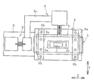
- FIG. 1 is an explanatory view illustrating the outline of the rubber extrusion device of the present invention in a plan view.
- FIG. 2 is an explanatory view illustrating the periphery of the head of FIG. 1 in a front view.
- FIG. 3 is an explanatory view illustrating the periphery of the head of FIG. 1 in a plan view.
- FIG. 4 is an explanatory view illustrating the inside of the periphery of the head in the AA cross section of FIG.
- FIG. 5 is an explanatory view illustrating a state in which the control plate of FIG. 3 is disposed at the center in the left-right direction of the head to extrude a rubber extrusion.
- FIG. 6 is an explanatory view illustrating a state in which the rubber extrusion is being extruded at a position where the control plate of FIG. 5 is slid to the left with respect to the head.
- FIG. 7 is an explanatory view exemplifying a state in which the rubber extrudate is being extruded at a position where the control plate of FIG. 6 is further slid to the left with respect to the head.
- FIG. 8 is an explanatory view illustrating another embodiment of the rubber extrusion device in a front view.
- the rubber extrusion device 1 of the present invention illustrated in FIGS. 1 to 4 includes a cylindrical cylinder 2, a screw 3 disposed inside the cylinder 2, and a head 4 disposed at the front end of the cylinder 2. There is.
- the head 4 has an extrusion channel 4a which penetrates back and forth.
- a base 6 is attached to the front of the head 4 with a control plate 5 interposed.
- the rubber extrusion device 1 has moving means 8 for sliding the control plate 5 along the space between the head 4 and the die 6. In FIG. 1, the moving means 8 and the like are omitted and not shown.
- the rubber extrusion device 1 further includes a sensor 10 and a control unit 11 to which detection data from the sensor 10 is input.
- a conveyor device 12 is disposed in front of the mouthpiece 6.
- the left and right direction and the up and down direction are shown as the direction along the space between the head 4 and the mouthpiece 6 respectively in the X arrow direction and the Y arrow direction.
- the X arrow direction and the Y arrow direction are directions orthogonal to each other, and the X arrow direction and the Y arrow direction are orthogonal to the extending direction of the extrusion flow path 4a.
- the direction in which the control plate 5 slides is not limited to the X arrow direction and the Y arrow direction, but may be an oblique direction along the gap between the head 4 and the base 6.
- the internal space narrows toward the front.
- the extrusion channel 4 a is in communication with the internal space of the cylinder 2.
- the control plate 5 is, for example, a plate made of metal, and has an adjustment channel 5a penetrating in the front and back direction.
- the die 6 has an extrusion port 7 which penetrates back and forth.
- the extrusion port 7 has a trapezoidal shape elongated in the width direction in a front view as illustrated in FIG. 2 and is formed in an asymmetrical shape.
- the extrusion port 7 is not limited to this shape, and a desired shape such as a circular shape, an elliptical shape, a semicircular shape, a square shape, or a rectangular shape is adopted.
- the base 6 is fixed to the front of the head 4 through the holding member 8a.
- the base 6 is fixed to the two holding members 8a arranged at intervals in the left-right direction of the base 6 by the fixing bolt 8b, and the respective holding members 8a are fixed to the head 4 by the fixing bolt 8b. ing.
- the extrusion channel 4a, the adjustment channel 5a, and the extrusion port 7 are in communication with each other. Therefore, the unvulcanized rubber R1 pushed into the extrusion flow path 4a from the internal space of the cylinder 2 passes through the adjustment flow path 5a and is extruded from the extrusion port 7 as a rubber extrudate R2.
- the cross-sectional areas of the extrusion channel 4a, the adjustment channel 5a, and the extrusion port 7 become smaller in order.
- a fixing plate 9 is attached to the left side surface of the head 4 so as to protrude outward, and a moving means 8 is installed on the fixing plate 9.
- a configuration having a servomotor and a ball screw that is rotated by the servomotor to move in the left-right direction is adopted as the moving means 8, and the tip of the ball screw is connected to the left side of the control plate 5. ing.
- a hydraulic cylinder can be adopted as the moving means 8.
- the installation location of the moving means 8 is not limited to the left side of the head 4 but may be any position. For example, it may be the right side of the head 4.
- the movement of the moving means 8 causes the ball screw to move back and forth, so that the control plate 5 slides in the left-right direction with respect to the head 4 and the cap 6. Along with this, the position of the communication region B of the extrusion channel 4a with respect to the adjustment channel 5a at the front end opening of the extrusion channel 4a changes.
- the control plate 5 is configured to be able to be fixed at a desired sliding position.
- the operation of the moving means 8 is controlled by the control unit 11 based on data detected by the sensor 10. Therefore, the control plate 5 is slid and fixed at a desired position under the control of the control unit 11.
- a predetermined amount of rubber material R such as a raw material rubber and a compounding agent is introduced into the internal space of the cylinder 2.
- the rubber material R is mixed and kneaded by the rotating screw 3.
- the unvulcanized rubber R1 pushed forward by the screw 3 is softened (plasticized) to a certain extent and is fed into the extrusion channel 4a to pass through the extrusion channel 4a.
- the front end opening of the extrusion flow channel 4 a is partially covered by the slide plate 5, and the front end opening of the adjustment flow channel 5 a is partially covered by the base 6.
- the unvulcanized rubber R1 that has passed through the extrusion flow path 4a and the adjustment flow path 5a is extruded from the extrusion port 7 of a desired shape, whereby a rubber extrudate R2 in which the cross-sectional shape is molded into a desired cross-sectional shape is manufactured.
- a rubber extrusion R2 such as a strip-like tire member formed into a predetermined shape is manufactured.
- the rubber extrudate R2 is conveyed by the conveyor device 12 to the next process while being extruded.
- the center position in the left-right direction of the extrusion flow path 4a is also a position coincident with the alternate long and short dash line CL.
- the center position M in the left-right direction of the extruded rubber R2 is offset to the right with respect to the center position CL in the left-right direction of the extrusion port 7 at a distance L forward from the die 6
- the extrudate R2 is curved to the right (the amount of curvature is d).
- the control plate 5 in the position of FIG. 5 is slid to the left with respect to the head 4 and the cap 6 as illustrated in FIG.
- the extruded unvulcanized rubber R1 has different pressures and flow rates in the direction perpendicular to the extrusion direction in the extrusion flow path 4a (has pressure distribution and flow rate distribution). Therefore, when the position of the communication region B of the extrusion channel 5a with respect to the adjustment channel 5a at the front end opening of the extrusion channel 4a is changed, the unvulcanized rubber passes through the extrusion channel 4a and the adjustment channel 5a and the extrusion port When extruded from 7, a change occurs in the pressure distribution (flow rate distribution). Along with this, it is possible to adjust the degree of curvature of the rubber extruded material R2 by acting on the rubber extruded material R2 with a force to bend to the left.
- the control plate 5 is slid further to the left with respect to the head 4 and the die 6, the force exerted on the rubber extrudate R2 to bend to the left is excessive, so the rubber extrudate R2 will curve to the left. Therefore, in the present invention, the position of the control plate 5 is appropriately adjusted, and the rubber extrudate R2 is extruded while being fixed as illustrated in FIG. Unintended bending of the rubber extrudate R2 is suppressed by sliding the control plate 5 along the space between the head 4 and the base 6 so that the force acting in the opposite direction to the unintended bending of the rubber extruded material R2 acts. can do. As a result, the curvature of the rubber extrusion R2 curved to the right is corrected, and it becomes possible to obtain a straight rubber extrusion R2 of a desired shape that is shaped in the shape of the extrusion port 7.
- the position (extrusion port 7) from which the rubber extrudate R2 is extruded can be maintained at a predetermined position.
- a line such as the conveyor device 12
- the present invention can be easily applied to the existing rubber extruder, as long as the control plate 5 interposed between the head 4 and the die 6 may be configured to be slidable.
- the displacement amount d of the lateral direction center position M of the extruded rubber R2 with respect to the lateral direction central position CL of the extrusion port 7 at the position of the distance L forward from the die 6 is sequentially detected by the sensor 10.
- the control unit 11 sequentially controls the position of the control plate 5 (adjustment flow path 5a) such that the amount of deviation d approaches zero (performs feedback control).
- the displacement amount d of the extruded rubber R is largest at a position where the distance L is about 500 mm. Therefore, the displacement amount d is detected by the sensor 10, for example, at a position where the distance L is 400 mm or more and 600 mm or less.
- Correlation data between fluctuation parameters such as rubber physical properties and extrusion conditions, the position of the control plate 5 slid along the gap between the head 4 and the die 6, and the degree of curvature of the rubber extrusion R2 when extruded at that position If it is accumulated to a certain extent, this correlation data is input to the control unit 11. Then, when the extrusion of the rubber extruded material R2 is started, the actual fluctuation parameter is input to the control unit 11, and the control plate 5 is input based on the data and the above-described correlation data input in advance. It is preset in a state of being placed in a predetermined position, and extrusion is performed so that the rubber extruded material R2 has a desired shape free from an unintended bending. After that, the feedback control described above is performed.
- the direction in which the control plate 5 is slid may be set in one direction (the direction in which the extrusion port 7 extends the longest in a front view) of the extrusion port 7 which is elongated as in this embodiment.
- the pressure distribution (flow rate distribution) of the unvulcanized rubber R1 when passing from the extrusion flow channel 4a to the adjustment flow channel 5a and the extrusion port 7 can be easily changed. Therefore, it becomes easy to suppress unintended bending of rubber extrusion thing R2.
- the control plate 5 is not limited to one, and a plurality of control plates may be provided. By sliding each control plate 5 independently, it is possible to adjust the degree of curvature of the rubber extrudate R2 in more detail.
- the control plate 5 is configured to be movable in the vertical direction as well as in the lateral direction with respect to the head 4 and the mouthpiece 6.
- the moving means 8 is disposed on the upper side as well.
- the moving means 8 disposed on the upper side adopts a configuration having a servomotor and a ball screw which is rotated by the servomotor to move in the axial direction, and the tip of the ball screw is connected to the upper surface of the control plate 5 ing.
- the moving means 8 is connected to another moving means 8 disposed on the left side of the head 4 by a connecting arm 8 c.
- the control plate 5 is sandwiched between the head 4 and the base 6 and is slidable in the left-right direction and the up-down direction.
- the moving means 8 disposed on the left side of the control plate 5 moves the moving means 8 and the control plate 5 disposed above the control plate 5 via the connecting arm 8 c in the left-right direction along the space between the head 4 and the mouthpiece 6. Slide to Therefore, in this embodiment, the control plate 5 is movable in any direction along the gap between the head 4 and the base 6.
- the pressure distribution (flow rate distribution) of the unvulcanized rubber R1 can be changed in more detail when the unvulcanized rubber R1 passes from the extrusion channel 4a to the adjustment channel 5a and the extrusion port 7 As it is possible, the degree of curvature of the rubber extrusion R2 can be adjusted in more detail. Therefore, it becomes possible to more reliably and reliably suppress the unintended bending of the rubber extrudate R2. Also in this embodiment, various specifications described in the previous embodiment can be applied.
Landscapes
- Engineering & Computer Science (AREA)
- Mechanical Engineering (AREA)
- Manufacturing & Machinery (AREA)
- Extrusion Moulding Of Plastics Or The Like (AREA)
Abstract
ゴム押出物の意図しない湾曲を抑制するとともに、ゴム押出物が押し出される位置を所定の位置に維持できるゴム押出装置およびゴム押出物の製造方法を提供する。ヘッド4に形成された押出流路4aおよび口金6に形成された押出口7と連通する調整流路5aを有するコントロールプレート5をヘッド4と口金6の間に介設し、コントロールプレート5をヘッド4と口金6との間に沿ってスライドさせて、押出流路4aの前端開口における調整流路5aに対する押出流路4aの連通領域Bの位置を変化させてコントロールプレート5を所望の位置に設定して、スクリュー3によりゴム材料Rを前方に押し出しつつ混合および混練した未加硫ゴムR1を、押出流路4aおよび調整流路5aを通過させて押出口7から押し出すことにより、押出し方向に対する湾曲量dを小さくした所望の形状のゴム押出物R2を製造する。
Description
本発明は、ゴム押出装置およびゴム押出物の製造方法に関し、さらに詳しくは、ゴム押出物の意図しない湾曲を抑制するとともに、ゴム押出物が押し出される位置を所定の位置に維持することができるゴム押出装置およびゴム押出物の製造方法に関するものである。
タイヤ等のゴム製品を製造する際には、ゴム押出装置によって未加硫ゴムを押出す押出し工程がある。ゴム押出装置では、内設されたスクリューによって未加硫ゴムを可塑化し、前端のヘッドに形成されている押出流路に送り込む。ヘッドの前端には所望の形状の押出口を有する口金が設置されていて、この押出口を未加硫ゴムが通過することにより所望の形状に型付けされたゴム押出物が製造される(例えば、特許文献1、2参照)。
ゴム種が異なるとゴム物性も異なり、同じゴム種であってロット毎にゴム物性には多少のばらつきがある。また、ロット毎に押出条件等にもばらつきがある。これらばらつきに起因して、同じ口金を使用して未加硫ゴムを押出しても、ゴム押出物は押出し方向に対して意図しない方向に湾曲し、所望の形状のゴム押出物を得られないことがある。このような場合、その都度、口金の裏側形状を修正加工したり、押出条件等を調整するために余分な作業工数が必要になる。
本発明の目的は、ゴム押出物の意図しない湾曲を抑制するとともに、ゴム押出物が押し出される位置を所定の位置に維持することができるゴム押出装置およびゴム押出物の製造方法を提供することにある。
上記目的を達成するため本発明のゴム押出装置は、筒状のシリンダと、このシリンダの内部空間に配置されるスクリューと、このシリンダの前端に設置されて前記内部空間と連通する押出流路を有するヘッドと、前記押出流路の前方に配置されて前記押出流路に連通する押出口を有する口金とを備えたゴム押出装置において、前記ヘッドと前記口金の間に介在して配置されて、前記押出流路および前記押出口と連通する調整流路を有するコントロールプレートと、前記ヘッドと前記口金との間に沿って前記コントロールプレートをスライドさせる移動手段とを備えて、前記コントロールプレートをスライドさせることにより、前記押出流路の前端開口における前記調整流路に対する前記押出流路の連通領域の位置が変化する構成にしたことを特徴とする。
本発明のゴム押出物の製造方法は、筒状のシリンダの内部空間にゴム材料を投入し、この内部空間に配置されたスクリューにより、前記ゴム材料を前方に押し出しつつ混合および混練した未加硫ゴムを、前記シリンダの前端に設置されたヘッドに形成されている押出流路に送り込み、前記押出流路の前方に配置された口金に形成されている押出口から前記未加硫ゴムをゴム押出物として押し出すゴム押出物の製造方法において、
前記押出流路および前記押出口と連通する調整流路を有するコントロールプレートを前記ヘッドと前記口金の間に介在させて配置し、前記コントロールプレートを前記ヘッドと前記口金との間に沿ってスライドさせて、前記押出流路の前端開口における前記調整流路に対する前記押出流路の連通領域の位置を変化させて前記コントロールプレートを所望の位置に設定して、前記未加硫ゴムを前記押出流路および前記調整流路を通過させて前記押出口から押し出すことにより、前記ゴム押出物の押出し方向に対する湾曲量を小さくすることを特徴とする。
前記押出流路および前記押出口と連通する調整流路を有するコントロールプレートを前記ヘッドと前記口金の間に介在させて配置し、前記コントロールプレートを前記ヘッドと前記口金との間に沿ってスライドさせて、前記押出流路の前端開口における前記調整流路に対する前記押出流路の連通領域の位置を変化させて前記コントロールプレートを所望の位置に設定して、前記未加硫ゴムを前記押出流路および前記調整流路を通過させて前記押出口から押し出すことにより、前記ゴム押出物の押出し方向に対する湾曲量を小さくすることを特徴とする。
本発明によれば、コントロールプレートをヘッドと口金の間に沿ってスライドさせることで、ヘッドの押出流路の前端開口におけるコントロールプレートの調整流路に対する押出流路の連通領域の位置が変化する。これに伴い、未加硫ゴムが押出流路および調整流路を通過して押出口から押し出される際に、圧力分布(流量分布)に変化が生じてゴム押出物の湾曲具合を調整することができる。それ故、ゴム押出物の意図しない湾曲と反対方向に湾曲させるように、コントロールプレートをスライドさせることで、ゴム押出物の意図しない湾曲を抑制することができる。
また、口金を移動せずに一定の位置に固定した状態で、コントロールプレートをスライドさせるだけなので、ゴム押出物が押し出される位置(押出口)を所定の位置に維持できる。これに伴い、ゴム押出物を次工程に搬送するラインを一定の位置に設定できるので、コントロールプレートのスライドに応じて搬送ラインを変化させる必要はない。
以下、本発明のゴム押出装置およびゴム押出物の製造方法を図に示した実施形態に基づいて説明する。
図1~図4に例示する本発明のゴム押出装置1は、筒状のシリンダ2と、シリンダ2の内部に配置されるスクリュー3と、シリンダ2の前端に配置されるヘッド4とを備えている。ヘッド4は前後に貫通する押出流路4aを有している。ヘッド4の前方にはコントロールプレート5を介在させて口金6が取り付けられている。このゴム押出装置1は、コントロールプレート5をヘッド4と口金6の間に沿ってスライドさせる移動手段8を有している。尚、図1では、移動手段8等を省略して図示していない。
この実施形態ではゴム押出装置1はさらに、センサ10と、センサ10による検知データが入力される制御部11とを備えている。口金6の前方にはコンベヤ装置12が配置されている。
図面では、ヘッド4と口金6の間に沿った方向として左右方向、上下方向がそれぞれ、X矢印方向、Y矢印方向で示されている。X矢印方向とY矢印方向とは互いに直交する方向であり、X矢印方向およびY矢印方向は押出流路4aが延在する方向と直交している。コントロールプレート5がスライドする方向は、X矢印方向やY矢印方向に限らず、ヘッド4と口金6の間に沿った斜めの方向の場合もある。
図4に例示するように、シリンダ2の前端部では内部空間が前方に向かって狭くなっている。押出流路4aはシリンダ2の内部空間と連通している。
コントロールプレート5は例えば金属製の板状体であり、前後に貫通する調整流路5aを有している。移動せずに一定位置に固定された状態のヘッド4および口金6の間に挟まれているコントロールプレート5は、ヘッド4の前端面および口金6の後端面に対して摺動する。したがって、コントロールプレート5とヘッド4、コントロールプレート5と口金6の互いに対向する面の少なくとも一方の面は、フッ素樹脂コーティングなどの低摩擦処理や、低摩擦材にするとよい。
口金6は前後に貫通する押出口7を有している。この実施形態では押出口7は、図2に例示するように正面視で幅方向に細長に延在する台形状であり、左右非対称の形状に形成されている。押出口7はこの形状に限らず、円形状、楕円形状、半円形状、正方形状、長方形状等、所望の形状が採用される。
口金6は保持部材8aを介してヘッド4の前方に固定されている。この実施形態では、口金6の左右方向に間隔をあけて配置された2つの保持部材8aに、口金6が固定ボルト8bにより固定され、それぞれの保持部材8aが固定ボルト8bによってヘッド4に固定されている。
押出流路4a、調整流路5aおよび押出口7は、連通している。したがって、シリンダ2の内部空間から押出流路4aに押し込まれた未加硫ゴムR1は、調整流路5aを通過して押出口7からゴム押出物R2として押し出される。この実施形態では、押出流路4a、調整流路5aおよび押出口7の横断面積は順に小さくなっている。
ヘッド4の左側面には固定プレート9が外側に張り出して取り付けられていて、固定プレート9には移動手段8が設置されている。この実施形態では移動手段8として、サーボモータと、サーボモータにより回転して左右方向に移動するボールねじとを有する構成が採用されていて、ボールねじの先端がコントロールプレート5の左側面に接続されている。
移動手段8はその他に例えば、油圧シリンダなどを採用することができる。移動手段8の設置場所はヘッド4の左側に限らず、任意の位置にすることができ、例えばヘッド4の右側にすることもできる。
移動手段8の作動によって、ボールねじが左右に進退するのでコントロールプレート5はヘッド4および口金6に対して左右方向にスライドする。これに伴い、押出流路4aの前端開口における調整流路5aに対する押出流路4aの連通領域Bの位置が変化する。コントロールプレート5は、スライドした所望の位置で固定できる構成になっている。移動手段8の作動はセンサ10による検知データに基づいて制御部11により制御される。そのため、制御部11の制御によってコントロールプレート5が所望の位置にスライドして固定される。
以下、本発明のゴム押出物の製造方法の手順を説明する。
ゴム押出装置1によってゴム押出物R2を製造する際には、原料ゴムおよび配合剤などの所定量のゴム材料Rを、シリンダ2の内部空間に投入する。ゴム材料Rは回転するスクリュー3により混合、混練される。スクリュー3により前方に押し出された未加硫ゴムR1は、ある程度柔らかくなって(可塑化されて)、押出流路4aに送り込まれて押出流路4aを通過する。
押出流路4aの前端開口はスライドプレート5によって一部が覆われていて、調整流路5aの前端開口は口金6によって一部が覆われている。押出流路4aおよび調整流路5aを通過した未加硫ゴムR1が、所望の形状の押出口7から押し出されることにより所望の断面形状に型付けされたゴム押出物R2が製造される。例えば、所定形状に形成されたストリップ状のタイヤ部材などのゴム押出物R2が製造される。ゴム押出物R2は押し出されつつ、コンベヤ装置12によって次工程に搬送される。
未加硫ゴムR1のゴム物性のばらつきや押出条件等によるばらつきがあると、同じ形状の押出口7で押出しても図5に例示するように、ゴム押出物R2が意図しない方向(左右方向や上下方向)に湾曲することがある。尚、図5~図7では、押出口7の左右方向(幅方向)中心位置を一点鎖線CLで示していて、ゴム押出物R2の左右方向(幅方向)中心位置を一点鎖線Mで示している。この実施形態では、押出流路4aの左右方向中心位置も一点鎖線CLと一致した位置になっている。図5では、口金6から前方に距離Lの位置で、ゴム押出物R2の左右方向中心位置Mが、押出口7の左右方向中心位置CLに対して右側にずれ量dだけ偏っていて、ゴム押出物R2が右側に湾曲している(湾曲量dになっている)。
ゴム押出物R2が真っ直ぐに押し出されず、図5に例示するように特定の方向に湾曲する原因は、未加硫ゴムR1のゴム物性のばらつきや押出条件(圧力、温度、流速など)、シリンダ2とスクリュー3とのマッチング等、多岐に渡り複合的なものだと考えられる。
そこで本発明では、図5の位置にあるコントロールプレート5を図6に例示するように、ヘッド4および口金6に対して左側にスライドさせる。押し出された未加硫ゴムR1は押出流路4aでは、押出方向に直交する方向に対して、異なる圧力、流速を有している(圧力分布、流速分布を有している)。そのため、押出流路4aの前端開口における調整流路5aに対する押出流路5aの連通領域Bの位置を変化させると、未加硫ゴムが押出流路4aおよび調整流路5aを通過して押出口7から押し出される際に、圧力分布(流量分布)に変化が生じる。これに伴い、ゴム押出物R2には左側に湾曲させる力が作用してゴム押出物R2の湾曲具合を調整することができる。
仮に、図7に例示するように、コントロールプレート5をヘッド4および口金6に対して一段と左側にスライドさせると、ゴム押出物R2に作用する左側に湾曲させる力が過大になるため、ゴム押出物R2は左側に湾曲することになる。そこで、本発明では、コントロールプレート5の位置を適切に調整して、図6に例示するように固定した状態にしてゴム押出物R2を押出す。ゴム押出物R2の意図しない湾曲と反対方向に湾曲させる力が作用するように、ヘッド4と口金6の間に沿ってコントロールプレート5をスライドさせることで、ゴム押出物R2の意図しない湾曲を抑制することができる。その結果、右側に湾曲していたゴム押出物R2の湾曲が是正され、押出口7の形状に型付けされた所望形状の真っ直ぐなゴム押出物R2を得ることが可能になる。
したがって本発明によれば、ゴム物性や押出条件等によるばらつきが生じても、ヘッド4と口金6の間に沿ったコントロールプレート5の位置を制御することで、意図しない湾曲を抑制した所望の形状のゴム押出物R2を安定して製造することができる。また、ゴム物性や押出条件等によるばらつきに応じて、その都度、口金6の形状を修正加工したり、押出条件等を調整するために従来行っていた余分な作業が不要、或いは、余分な作業が最小限になる。そのため、ゴム押出物R2の生産性を向上させるには有利になる。
しかも、ゴム押出物R2の意図しない湾曲を是正するには、口金6は一定の位置に固定した状態で、コントロールプレート5をスライドさせるだけでよい。それ故、ゴム押出物R2が押し出される位置(押出口7)を所定の位置に維持することができる。これに伴い、ゴム押出物R2を次工程に搬送するライン(コンベヤ装置12など)を一定の位置に設定できるので、コントロールプレート5のスライドに応じてその都度、搬送ラインを変化させる必要はない。そのため、押出工程の後工程のレイアウトに影響を及ぼすことがない。また、本発明はヘッド4と口金6の間に介在させたコントロールプレート5をスライド可能な構成にすればよいので、既存のゴム押出機に対しても容易に適用することができる。
コントロールプレート5が図5の位置から図6の位置にスライドした場合は、押出流路4aの前端開口における調整流路5aに対する押出流路4aの連通領域Bの位置が変化するだけで連通領域Bの面積は変化していない。しかし、コントロールプレート5が図6の位置から図7の位置にスライドした場合は、連通領域Bの位置が変化するだけでなく、連通領域Bの面積も変化している。このように連通領域Bの位置および面積を変化させると、押出流路4aおよび調整流路5aを通過して押出口7から押し出される際の未加硫ゴムR1の圧力分布(流量分布)をより大きく変化させることができる。そのため、ゴム押出物R2の湾曲具合の是正効果を向上させるには有利になる。
この実施形態では、口金6から前方に距離Lの位置における押出口7の左右方向中心位置CLに対するゴム押出物R2の左右方向中心位置Mの左右方向のずれ量dをセンサ10により逐次検知する。制御部11では、ずれ量dがゼロに近づくようにコントロールプレート5(調整流路5a)の位置を逐次制御する(フィードバック制御をする)。ゴム押出物Rのずれ量dは、距離Lが500mm程度の位置で最も大きくなるので、センサ10によってずれ量dを検知するのは、例えば距離Lが400mm以上600mm以下の位置にする。
ゴム物性や押出条件等の変動パラメータと、ヘッド4と口金6の間に沿ってスライドさせたコントロールプレート5の位置と、その位置で押出した場合のゴム押出物R2の湾曲具合との相関データがある程度蓄積されている場合は、この相関データを制御部11に入力しておく。そして、ゴム押出物R2の押出しを開始する際には、実際の変動パラメータを制御部11に入力して、これらのデータと、予め入力されている上述した相関データに基づいて、コントロールプレート5を所定位置に配置した状態でプリセットし、ゴム押出物R2が意図しない湾曲が生じない所望の形状になるように押出をする。その後は、上述したフィードバック制御を行う。
本発明を用いて、例えばタイヤ構成部材となるゴム押出物R2を製造すると、意図しない湾曲が抑制された所望の形状にすることができる。そのため、このゴム押出物R2を用いてタイヤを製造すると、タイヤのユニフォミティを向上させるには有利になる。
コントロールプレート5をスライドさせる方向は、この実施形態のように押出口7の細長に延在されている一方向(押出口7が正面視で最も長く延在している方向)に設定するとよい。これにより、押出流路4aから調整流路5aおよび押出口7を通過する際の未加硫ゴムR1の圧力分布(流量分布)を大きく変化させ易い。そのため、ゴム押出物R2の意図しない湾曲を抑制し易くなる。
コントロールプレート5は、1枚に限らず複数枚備えることもできる。それぞれのコントロールプレート5を独立してスライドさせることで、ゴム押出物R2の湾曲具合をより詳細に調整することが可能になる。
図8に例示するゴム押出装置1の他の実施形態では、コントロールプレート5が、ヘッド4および口金6に対して左右方向だけでなく上下方向にも移動できる構成になっている。具体的には、ヘッド4の左側に加えて上側にも移動手段8が配置されている。上側に配置された移動手段8にはサーボモータと、サーボモータにより回転して軸方向に移動するボールねじとを有する構成が採用されていて、ボールねじの先端がコントロールプレート5の上面に接続されている。この移動手段8は、ヘッド4の左側に配置された別の移動手段8と連結アーム8cによって連結されている。コントロールプレート5は、ヘッド4と口金6に挟まれて、左右方向および上下方向にスライド可能になっている。
コントロールプレート5の左側に配置された移動手段8は、連結アーム8cを介してコントロールプレート5の上方に配置された移動手段8およびコントロールプレート5を、ヘッド4および口金6の間に沿って左右方向にスライドさせる。したがって、この実施形態ではコントロールプレート5は、ヘッド4と口金6との間に沿って任意の方向に移動可能になっている。
この実施形態では、未加硫ゴムR1が押出流路4aから調整流路5aおよび押出口7を通過する際に、未加硫ゴムR1の圧力分布(流量分布)をより詳細に変化させることができるので、ゴム押出物R2の湾曲具合をより詳細に調整できる。それ故、ゴム押出物R2の意図しない湾曲をより精度よく確実に抑制することが可能になる。この実施形態においても、先の実施形態で説明した様々な仕様を適用することができる。
1 ゴム押出装置
2 シリンダ
3 スクリュー
4 ヘッド
4a 押出流路
5 コントロールプレート
5a 調整流路
6 口金
7 押出口
8 移動手段
8a 保持部材
8b 固定ボルト
8c 連結アーム
9 固定プレート
10 センサ
11 制御部
12 コンベヤ装置
R ゴム材料
R1 未加硫ゴム
R2 ゴム押出物
2 シリンダ
3 スクリュー
4 ヘッド
4a 押出流路
5 コントロールプレート
5a 調整流路
6 口金
7 押出口
8 移動手段
8a 保持部材
8b 固定ボルト
8c 連結アーム
9 固定プレート
10 センサ
11 制御部
12 コンベヤ装置
R ゴム材料
R1 未加硫ゴム
R2 ゴム押出物
Claims (7)
- 筒状のシリンダと、このシリンダの内部空間に配置されるスクリューと、このシリンダの前端に設置されて前記内部空間と連通する押出流路を有するヘッドと、前記押出流路の前方に設置されて前記押出流路に連通する押出口を有する口金とを備えたゴム押出装置において、
前記ヘッドと前記口金の間に介在して配置されて、前記押出流路および前記押出口と連通する調整流路を有するコントロールプレートと、前記ヘッドと前記口金との間に沿って前記コントロールプレートをスライドさせる移動手段とを備えて、前記コントロールプレートをスライドさせることにより、前記押出流路の前端開口における前記調整流路に対する前記押出流路の連通領域の位置が変化する構成にしたことを特徴とするゴム押出装置。 - 前記コントロールプレートをスライドさせることにより、前記押出流路の前端開口における前記調整流路に対する前記押出流路の連通領域の面積が変化する構成にした請求項1に記載のゴム押出装置。
- 前記押出口が一方向に細長に延在して形成されていて、前記移動手段により前記コントロールプレートを前記一方向にスライド可能な構成にした請求項1または2に記載のゴム押出装置。
- 前記移動手段により前記コントロールプレートを任意の方向にスライド可能な構成にした請求項1~3のいずれかに記載のゴム押出装置。
- 前記移動手段の作動を制御することにより、前記コントロールプレートを所望の位置にスライドさせる制御部を有する請求項1~4のいずれかに記載のゴム押出装置。
- 前記押出口から押し出されたゴム押出物の押出し方向に対する湾曲量を検知するセンサを有し、このセンサの検知データに基づいて前記制御部により前記コントロールプレートを所望の位置にスライドさせる構成にした請求項1~5のいずれかに記載のゴム押出装置。
- 筒状のシリンダの内部空間にゴム材料を投入し、この内部空間に配置されたスクリューにより、前記ゴム材料を前方に押し出しつつ混合および混練した未加硫ゴムを、前記シリンダの前端に設置されたヘッドに形成されている押出流路に送り込み、前記押出流路の前方に配置された口金に形成されている押出口から前記未加硫ゴムをゴム押出物として押し出すゴム押出物の製造方法において、
前記押出流路および前記押出口と連通する調整流路を有するコントロールプレートを前記ヘッドと前記口金の間に介在させて配置し、前記コントロールプレートを前記ヘッドと前記口金との間に沿ってスライドさせて、前記押出流路の前端開口における前記調整流路に対する前記押出流路の連通領域の位置を変化させて前記コントロールプレートを所望の位置に設定して、前記未加硫ゴムを前記押出流路および前記調整流路を通過させて前記押出口から押し出すことにより、前記ゴム押出物の押出し方向に対する湾曲量を小さくすることを特徴とするゴム押出物の製造方法。
Priority Applications (3)
| Application Number | Priority Date | Filing Date | Title |
|---|---|---|---|
| US16/641,147 US11534950B2 (en) | 2017-08-21 | 2018-06-07 | Rubber extrusion device and method for manufacturing rubber extrudate |
| EP18849262.3A EP3674070B1 (en) | 2017-08-21 | 2018-06-07 | Rubber extrusion device and method for manufacturing rubber extruded object |
| CN201880040378.0A CN110753609B (zh) | 2017-08-21 | 2018-06-07 | 橡胶挤出装置及橡胶挤出物的制造方法 |
Applications Claiming Priority (2)
| Application Number | Priority Date | Filing Date | Title |
|---|---|---|---|
| JP2017158752A JP6665840B2 (ja) | 2017-08-21 | 2017-08-21 | ゴム押出装置およびゴム押出物の製造方法 |
| JP2017-158752 | 2017-08-21 |
Publications (1)
| Publication Number | Publication Date |
|---|---|
| WO2019039041A1 true WO2019039041A1 (ja) | 2019-02-28 |
Family
ID=65439423
Family Applications (1)
| Application Number | Title | Priority Date | Filing Date |
|---|---|---|---|
| PCT/JP2018/021896 Ceased WO2019039041A1 (ja) | 2017-08-21 | 2018-06-07 | ゴム押出装置およびゴム押出物の製造方法 |
Country Status (5)
| Country | Link |
|---|---|
| US (1) | US11534950B2 (ja) |
| EP (1) | EP3674070B1 (ja) |
| JP (1) | JP6665840B2 (ja) |
| CN (1) | CN110753609B (ja) |
| WO (1) | WO2019039041A1 (ja) |
Families Citing this family (1)
| Publication number | Priority date | Publication date | Assignee | Title |
|---|---|---|---|---|
| CN114559590B (zh) * | 2022-02-23 | 2024-03-19 | 高扬 | 一种高硅氧模压系统 |
Citations (10)
| Publication number | Priority date | Publication date | Assignee | Title |
|---|---|---|---|---|
| JPS5020593B1 (ja) * | 1970-12-23 | 1975-07-16 | ||
| JPS6097824A (ja) * | 1983-11-02 | 1985-05-31 | Bridgestone Corp | 押出機用ヘッド |
| JPH0234450A (ja) * | 1988-07-25 | 1990-02-05 | Tokai Kogyo Kk | ウェザーストリップ、並びにその成形方法及び装置 |
| JPH03143609A (ja) * | 1989-10-31 | 1991-06-19 | Meiji Rubber & Chem Co Ltd | ゴムホース製造用マンドレル並びに該マンドレルを用いる押出装置及び該装置によるゴムホースの製造方法 |
| JP2000289084A (ja) * | 1999-04-12 | 2000-10-17 | Sekisui Chem Co Ltd | 押出成形用金型 |
| JP2008126560A (ja) | 2006-11-22 | 2008-06-05 | Bridgestone Corp | ゴム成形装置、ゴム部材の製造装置及び製造方法 |
| JP2009061691A (ja) * | 2007-09-06 | 2009-03-26 | Toyo Tire & Rubber Co Ltd | 円環状ゴム部材の製造方法及びその製造装置 |
| JP2012187712A (ja) * | 2011-03-08 | 2012-10-04 | Toyo Tire & Rubber Co Ltd | シート状ゴム成形装置及び方法 |
| JP2013216069A (ja) | 2012-04-12 | 2013-10-24 | Toyo Tire & Rubber Co Ltd | ダイユニット |
| JP2014172250A (ja) * | 2013-03-07 | 2014-09-22 | Toyo Tire & Rubber Co Ltd | ゴム部材成型装置 |
Family Cites Families (10)
| Publication number | Priority date | Publication date | Assignee | Title |
|---|---|---|---|---|
| US3830610A (en) | 1970-12-23 | 1974-08-20 | Bridgestone Tire Co Ltd | Apparatus for forming rubber products such as a tread rubber by extrusion |
| JPS5020593A (ja) | 1973-06-25 | 1975-03-04 | ||
| JP3834199B2 (ja) | 2000-11-22 | 2006-10-18 | 住友ゴム工業株式会社 | ゴム成形方法およびゴム成形装置 |
| US6663378B2 (en) * | 2001-09-27 | 2003-12-16 | Corning Incorporated | Apparatus for correcting bow in a honeycomb extrudate |
| JP2006335017A (ja) * | 2005-06-06 | 2006-12-14 | Bridgestone Corp | 帯状ゴムの押出し方法および装置 |
| JP4822948B2 (ja) * | 2006-06-20 | 2011-11-24 | 株式会社ブリヂストン | ゴム被覆装置及びゴム被覆コードの製造方法 |
| RO126104A2 (ro) * | 2009-09-22 | 2011-03-30 | Inoe 2000-Institutul De Cercetări Pentru Hidraulică Şi Pneumatică | Metodă şi aparat de corelare şi reglare transfer şnur extruder tunel |
| JP2012091340A (ja) * | 2010-10-25 | 2012-05-17 | Bridgestone Corp | 押出成形装置及び成形品の製造方法 |
| WO2012063891A1 (ja) | 2010-11-11 | 2012-05-18 | 東洋製罐株式会社 | 溶融樹脂の曲がり矯正装置と溶融樹脂の曲がり矯正方法 |
| JP6520968B2 (ja) | 2017-02-16 | 2019-05-29 | 横浜ゴム株式会社 | ゴム押出装置およびゴム押出物の製造方法 |
-
2017
- 2017-08-21 JP JP2017158752A patent/JP6665840B2/ja active Active
-
2018
- 2018-06-07 EP EP18849262.3A patent/EP3674070B1/en active Active
- 2018-06-07 US US16/641,147 patent/US11534950B2/en active Active
- 2018-06-07 CN CN201880040378.0A patent/CN110753609B/zh active Active
- 2018-06-07 WO PCT/JP2018/021896 patent/WO2019039041A1/ja not_active Ceased
Patent Citations (10)
| Publication number | Priority date | Publication date | Assignee | Title |
|---|---|---|---|---|
| JPS5020593B1 (ja) * | 1970-12-23 | 1975-07-16 | ||
| JPS6097824A (ja) * | 1983-11-02 | 1985-05-31 | Bridgestone Corp | 押出機用ヘッド |
| JPH0234450A (ja) * | 1988-07-25 | 1990-02-05 | Tokai Kogyo Kk | ウェザーストリップ、並びにその成形方法及び装置 |
| JPH03143609A (ja) * | 1989-10-31 | 1991-06-19 | Meiji Rubber & Chem Co Ltd | ゴムホース製造用マンドレル並びに該マンドレルを用いる押出装置及び該装置によるゴムホースの製造方法 |
| JP2000289084A (ja) * | 1999-04-12 | 2000-10-17 | Sekisui Chem Co Ltd | 押出成形用金型 |
| JP2008126560A (ja) | 2006-11-22 | 2008-06-05 | Bridgestone Corp | ゴム成形装置、ゴム部材の製造装置及び製造方法 |
| JP2009061691A (ja) * | 2007-09-06 | 2009-03-26 | Toyo Tire & Rubber Co Ltd | 円環状ゴム部材の製造方法及びその製造装置 |
| JP2012187712A (ja) * | 2011-03-08 | 2012-10-04 | Toyo Tire & Rubber Co Ltd | シート状ゴム成形装置及び方法 |
| JP2013216069A (ja) | 2012-04-12 | 2013-10-24 | Toyo Tire & Rubber Co Ltd | ダイユニット |
| JP2014172250A (ja) * | 2013-03-07 | 2014-09-22 | Toyo Tire & Rubber Co Ltd | ゴム部材成型装置 |
Non-Patent Citations (1)
| Title |
|---|
| See also references of EP3674070A4 |
Also Published As
| Publication number | Publication date |
|---|---|
| JP6665840B2 (ja) | 2020-03-13 |
| US11534950B2 (en) | 2022-12-27 |
| EP3674070A1 (en) | 2020-07-01 |
| EP3674070B1 (en) | 2025-06-25 |
| JP2019034520A (ja) | 2019-03-07 |
| US20200198207A1 (en) | 2020-06-25 |
| EP3674070A4 (en) | 2021-05-26 |
| CN110753609A (zh) | 2020-02-04 |
| CN110753609B (zh) | 2022-03-11 |
Similar Documents
| Publication | Publication Date | Title |
|---|---|---|
| JP6520967B2 (ja) | ゴム押出装置およびゴム押出物の製造方法 | |
| EP3283273B1 (en) | Extruder system for extruding cord reinforced extrudate | |
| US10821643B2 (en) | System and method for adjusting the land channel length on an extrusion die | |
| JP6583303B2 (ja) | ゴム押出装置およびゴム押出物の製造方法 | |
| US11420375B2 (en) | Extruder and method for extruding cord reinforced tire components | |
| JP6520968B2 (ja) | ゴム押出装置およびゴム押出物の製造方法 | |
| WO2019039041A1 (ja) | ゴム押出装置およびゴム押出物の製造方法 | |
| JP2018130895A (ja) | ゴム押出装置およびゴム押出物の製造方法 | |
| JP6862746B2 (ja) | ゴム押出物の製造方法 | |
| JP2019048408A (ja) | ゴム押出装置およびゴム押出物の製造方法 |
Legal Events
| Date | Code | Title | Description |
|---|---|---|---|
| NENP | Non-entry into the national phase |
Ref country code: DE |
|
| ENP | Entry into the national phase |
Ref document number: 2018849262 Country of ref document: EP Effective date: 20200323 |
|
| WWG | Wipo information: grant in national office |
Ref document number: 2018849262 Country of ref document: EP |