WO2019059176A1 - 画像露光装置、および画像露光方法 - Google Patents
画像露光装置、および画像露光方法 Download PDFInfo
- Publication number
- WO2019059176A1 WO2019059176A1 PCT/JP2018/034459 JP2018034459W WO2019059176A1 WO 2019059176 A1 WO2019059176 A1 WO 2019059176A1 JP 2018034459 W JP2018034459 W JP 2018034459W WO 2019059176 A1 WO2019059176 A1 WO 2019059176A1
- Authority
- WO
- WIPO (PCT)
- Prior art keywords
- light
- image display
- display device
- recording medium
- image
- Prior art date
- Legal status (The legal status is an assumption and is not a legal conclusion. Google has not performed a legal analysis and makes no representation as to the accuracy of the status listed.)
- Ceased
Links
Images


Classifications
-
- G—PHYSICS
- G03—PHOTOGRAPHY; CINEMATOGRAPHY; ANALOGOUS TECHNIQUES USING WAVES OTHER THAN OPTICAL WAVES; ELECTROGRAPHY; HOLOGRAPHY
- G03F—PHOTOMECHANICAL PRODUCTION OF TEXTURED OR PATTERNED SURFACES, e.g. FOR PRINTING, FOR PROCESSING OF SEMICONDUCTOR DEVICES; MATERIALS THEREFOR; ORIGINALS THEREFOR; APPARATUS SPECIALLY ADAPTED THEREFOR
- G03F7/00—Photomechanical, e.g. photolithographic, production of textured or patterned surfaces, e.g. printing surfaces; Materials therefor, e.g. comprising photoresists; Apparatus specially adapted therefor
- G03F7/20—Exposure; Apparatus therefor
- G03F7/2002—Exposure; Apparatus therefor with visible light or UV light, through an original having an opaque pattern on a transparent support, e.g. film printing, projection printing; by reflection of visible or UV light from an original such as a printed image
- G03F7/2008—Exposure; Apparatus therefor with visible light or UV light, through an original having an opaque pattern on a transparent support, e.g. film printing, projection printing; by reflection of visible or UV light from an original such as a printed image characterised by the reflectors, diffusers, light or heat filtering means or anti-reflective means used
-
- G—PHYSICS
- G03—PHOTOGRAPHY; CINEMATOGRAPHY; ANALOGOUS TECHNIQUES USING WAVES OTHER THAN OPTICAL WAVES; ELECTROGRAPHY; HOLOGRAPHY
- G03B—APPARATUS OR ARRANGEMENTS FOR TAKING PHOTOGRAPHS OR FOR PROJECTING OR VIEWING THEM; APPARATUS OR ARRANGEMENTS EMPLOYING ANALOGOUS TECHNIQUES USING WAVES OTHER THAN OPTICAL WAVES; ACCESSORIES THEREFOR
- G03B27/00—Photographic printing apparatus
- G03B27/32—Projection printing apparatus, e.g. enlarger, copying camera
- G03B27/52—Details
- G03B27/522—Projection optics
-
- G—PHYSICS
- G03—PHOTOGRAPHY; CINEMATOGRAPHY; ANALOGOUS TECHNIQUES USING WAVES OTHER THAN OPTICAL WAVES; ELECTROGRAPHY; HOLOGRAPHY
- G03B—APPARATUS OR ARRANGEMENTS FOR TAKING PHOTOGRAPHS OR FOR PROJECTING OR VIEWING THEM; APPARATUS OR ARRANGEMENTS EMPLOYING ANALOGOUS TECHNIQUES USING WAVES OTHER THAN OPTICAL WAVES; ACCESSORIES THEREFOR
- G03B17/00—Details of cameras or camera bodies; Accessories therefor
- G03B17/48—Details of cameras or camera bodies; Accessories therefor adapted for combination with other photographic or optical apparatus
- G03B17/50—Details of cameras or camera bodies; Accessories therefor adapted for combination with other photographic or optical apparatus with both developing and finishing apparatus
- G03B17/52—Details of cameras or camera bodies; Accessories therefor adapted for combination with other photographic or optical apparatus with both developing and finishing apparatus of the Land type
-
- G—PHYSICS
- G03—PHOTOGRAPHY; CINEMATOGRAPHY; ANALOGOUS TECHNIQUES USING WAVES OTHER THAN OPTICAL WAVES; ELECTROGRAPHY; HOLOGRAPHY
- G03B—APPARATUS OR ARRANGEMENTS FOR TAKING PHOTOGRAPHS OR FOR PROJECTING OR VIEWING THEM; APPARATUS OR ARRANGEMENTS EMPLOYING ANALOGOUS TECHNIQUES USING WAVES OTHER THAN OPTICAL WAVES; ACCESSORIES THEREFOR
- G03B27/00—Photographic printing apparatus
- G03B27/02—Exposure apparatus for contact printing
- G03B27/04—Copying apparatus without a relative movement between the original and the light source during exposure, e.g. printing frame or printing box
-
- G—PHYSICS
- G03—PHOTOGRAPHY; CINEMATOGRAPHY; ANALOGOUS TECHNIQUES USING WAVES OTHER THAN OPTICAL WAVES; ELECTROGRAPHY; HOLOGRAPHY
- G03F—PHOTOMECHANICAL PRODUCTION OF TEXTURED OR PATTERNED SURFACES, e.g. FOR PRINTING, FOR PROCESSING OF SEMICONDUCTOR DEVICES; MATERIALS THEREFOR; ORIGINALS THEREFOR; APPARATUS SPECIALLY ADAPTED THEREFOR
- G03F7/00—Photomechanical, e.g. photolithographic, production of textured or patterned surfaces, e.g. printing surfaces; Materials therefor, e.g. comprising photoresists; Apparatus specially adapted therefor
- G03F7/20—Exposure; Apparatus therefor
- G03F7/2051—Exposure without an original mask, e.g. using a programmed deflection of a point source, by scanning, by drawing with a light beam, using an addressed light or corpuscular source
Definitions
- the present invention relates to an image exposure apparatus and an image exposure method, and more particularly to an image exposure apparatus for recording an image on a photosensitive recording medium and an image exposure method.
- Patent Document 1 discloses an apparatus in which a collimation layer is disposed between a light emitting display screen and an instant film.
- the collimation layer blocks non-parallel light from the light emitting display screen, so lenses and the like in the device can be eliminated.
- the present invention has been made in view of such circumstances, and it is an object of the present invention to provide an image exposure apparatus and an image exposure method capable of suppressing a decrease in image quality caused by stray light.
- an image exposure apparatus comprises an image display device having pixels, a photosensitive recording medium for recording an image of the image display device, and an exposure surface of the photosensitive recording medium.
- a photosensitive recording medium support unit for supporting the display device so as to face the display device; a collimating unit provided between the image display device and the photosensitive recording medium support unit for converting light from pixels into parallel light; And an absorption layer provided between the light-sensitive recording medium support and the light transmission of light from the pixel at 50% or less.
- the absorbing layer is a neutral density filter.
- the collimating unit is at least one selected from a light control unit formed by laminating a slit, a fiber optic plate, a capillary plate, and three or more transmission members having a plurality of openings. .
- the light transmittance of the absorption layer is 20% or less.
- the light transmittance of the absorbing layer is 0.001% or more.
- the light quantity which directly reaches the position of the exposure surface of the photosensitive recording medium supported by the photosensitive recording medium support from the image display apparatus is A
- the photosensitive recording medium from the image display B / A is 1/10000 or less
- B is the amount of light indirectly reaching the position of the exposure surface of the above.
- the image display apparatus has pixels arranged in a two-dimensional manner, and simultaneously exposes all the two-dimensional areas of the exposure surface of the photosensitive recording medium.
- At least one of the image display device and the photosensitive recording medium supported by the photosensitive recording medium support portion has pixels in which the image display device is arranged in a one-dimensional shape, And a scanning unit configured to scan in a direction perpendicular to the arrangement direction of the pixels of the image display device.
- the image display device has pixels arranged in a two-dimensional manner on an area smaller than the exposure surface of the photosensitive recording medium, and the image display device and the photosensitive recording medium
- a scanning unit is provided which scans at least one of the photosensitive recording media supported by the support along both the arrangement direction of the pixels of the image display device and the direction perpendicular to the arrangement direction of the pixels.
- adjacent exposure ranges partially overlap in the exposure range with light from pixels.
- the image display apparatus is detachable.
- the present invention it is possible to reduce the occurrence of image blurring due to stray light and to suppress the deterioration of image quality.
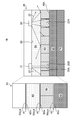
- FIG. 1 is a diagram for explaining the principle of the present invention.
- FIG. 2 is a flow chart showing the exposure method of the present invention.
- FIG. 3 is an exploded perspective view of the image exposure apparatus of the first embodiment.
- FIG. 4 is a cross-sectional view of the image exposure apparatus of the first embodiment.
- FIG. 5 is a perspective view of the image exposure apparatus of the second embodiment.
- FIG. 6 is a perspective view of a modification of the image exposure apparatus of the second embodiment.
- FIG. 7 is a perspective view of the image exposure apparatus of the third embodiment.
- FIG. 8 is a perspective view of a modification of the image exposure apparatus of the third embodiment.
- the image exposure device 10 includes an image display device 20 and a photosensitive recording medium support 70 for supporting the photosensitive recording medium 40.
- the photosensitive recording medium support unit 70 may support the photosensitive recording medium 40 directly or indirectly.
- the image display device 20 includes pixels 21. Light 22 from the pixel 21 is emitted from the image display surface 23 of the image display device 20.
- the pixel 21 is the minimum unit of color information that constitutes the image display surface 23. By including the pixels 21, the image display device 20 can display an image.
- the image display device 20 comprises a plurality of pixels 21 for displaying an image.
- a CRT (Cathode Ray Tube) display device or the like can be applied.
- the image display device 20 is not limited to the above-described structure as long as the pixel 21 can display some color information and can display an image.
- the pixel 21 when the light of the backlight unit is emitted through the pixel 21 as represented by a liquid crystal display device, and as represented by an organic light emitting diode display device, for example, the pixel 21 is represented by a liquid crystal display device. And when it itself emits light.
- the image display surface 23 of the image display device 20 may have the pixels 21 arranged in a two-dimensional manner, or may have the pixels 21 arranged in a one-dimensional manner. Further, the two-dimensional image display surface 23 may be rectangular in plan view, or may be a shape other than rectangular.
- the photosensitive recording medium support unit 70 supports the photosensitive recording medium 40 such that the photosensitive recording medium 40 is disposed at a position facing the image display surface 23 of the image display device 20.
- the structure of the photosensitive recording medium support portion 70 is not particularly limited as long as the photosensitive recording medium support portion 40 can be supported.
- the photosensitive recording medium 40 is not particularly limited as long as the photosensitive recording medium 40 can be exposed by the absorbing layer 60 and the parallel light 22A that has passed through the collimating unit 50 and can form an image.
- the photosensitive recording medium 40 comprises, for example, a support and a photosensitive material provided on the support.
- the photosensitive recording medium 40 has an exposure surface 40A.
- the photosensitive recording medium 40 may be any photosensitive product such as a photographic film, a printing plate, a printing paper or a blueprint, a positive photosensitive paper, a plate for making plate, a photoresist, an instant film, and the like. It is preferred to apply an instant film.
- a collimating unit 50 is provided between the image display device 20 and the photosensitive recording medium support 70 for supporting the photosensitive recording medium 40.
- the collimator unit 50 converts the light 22 from the pixel 21 into parallel light 22A.
- the collimating unit 50 passes parallel light 22A in the light 22 onto the photosensitive recording medium 40 (see the pixel 21 on the right side of FIG. 1).
- the collimating unit 50 causes the parallel light 22A in the light 22 to reach the photosensitive recording medium 40.
- the parallel light 22A exposes the photosensitive recording medium 40. Since the collimated portion 50 irradiates the parallel light 22A to the exposure surface 40A of the photosensitive recording medium 40, the occurrence of blurring or the like on the image formed on the photosensitive recording medium 40 is reduced, and the deterioration of the image quality is suppressed. Ru.
- the collimating unit 50 prevents the exposure surface 40A of the photosensitive recording medium 40 from being exposed to light other than the parallel light 22A that causes the blurring of the image.
- the parallel light 22A means that the light which passes through the collimating unit 50 and is irradiated to the exposure surface 40A of the photosensitive recording medium 40 is parallel to each other.
- parallel includes substantially parallel, and includes parallel to such an extent that an image formed on the photosensitive recording medium 40 is not blurred.
- the parallel light 22 ⁇ / b> A includes light orthogonal to or substantially orthogonal to the image display surface 23 of the image exposure apparatus 10.
- the parallel light 22A is a light inclined by a predetermined angle to the image display surface 23 of the image exposure device 10. It may be.
- the light inclined by the predetermined angle reaches the exposure surface 40A of the photosensitive recording medium 40 and the other light does not reach the exposure surface 40A of the photosensitive recording medium 40, the light inclined by the predetermined angle becomes parallel light.
- the structure of the collimating unit 50 is not particularly limited as long as the light 22 from the pixel 21 can be converted into the parallel light 22A.
- a light control unit formed by laminating a slit, a fiber optic plate, a capillary plate, and three or more transmission members having a plurality of openings can be applied.
- the slit (referred to as a louver) is composed of a plurality of light transmitting portions and a light absorber so as not to reach the adjacent space.
- the fiber optic plate is a plate including a plurality of two-dimensionally arranged optical fibers for transferring light and an absorber glass for absorbing light leaked from the optical fibers.
- the capillary plate is a plate composed of a plurality of two-dimensionally arranged capillaries (capillaries) having a diameter of several tens of ⁇ m or less.
- the light control unit formed by laminating three or more layers of transmission members having a plurality of openings is a laminated body in which three or more layers of parallax barriers are stacked.
- the parallax barrier is a light shielding layer having an opening that controls the direction in which light travels.
- the image exposure apparatus 10 includes the collimating unit 50, an optical system such as a lens for forming the light from the image exposure apparatus 10 on the photosensitive recording medium 40 can be eliminated.
- An absorbing layer 60 is provided between the image display device 20 and the photosensitive recording medium 40.
- the absorbing layer 60 is disposed between the image display device 20 and the collimating unit 50.
- the absorbing layer 60 can be provided between the photosensitive recording medium 40 and the collimating unit 50.
- the absorption layer 60 has a light transmittance of 50% or less of the light from the pixel 21 in the wavelength range used for exposure.
- the wavelength range used for exposure is preferably in the range of 400 nm to 700 nm which is a visible light range.
- T I / I 0 (%).
- the average light transmittance can be obtained as an average value of light transmittances at predetermined intervals (for example, every 10 nm) between 400 nm and 700 nm.
- the absorption layer 60 is preferably a neutral density filter (hereinafter, an ND (Neutral Density) filter).
- the ND filter means a filter of neutral optical density, and in the wavelength range used for exposure, absorbs light evenly without affecting the wavelength (50% to 99.999% in terms of absorptivity; light transmittance) In the range of 0.001% to 50%).
- the ND filter can uniformly absorb light in the wavelength range used for exposure, so the influence of stray light can be reduced as described later.
- ND filters There are two types of ND filters: absorption and reflection. Because stray light is caused by reflected light, an absorption-type ND filter that can suppress reflected light is preferable to a reflection-type ND filter.
- the ND filter can be made by mixing the absorbing dye into the support, or can be made by applying a transparent material mixed with the dye to the support.
- the characteristics of the ND filter are generally defined by optical density (OD).
- OD optical density
- T ⁇ 1 log 10 (1 / T) (where T ⁇ 1).
- the ND filter is illustrated as the absorption layer 60, it is not particularly limited as long as the light transmittance of the light from the pixel 21 is 50% or less in the wavelength range used for exposure.
- the stray light 22 B is light that indirectly reaches the photosensitive recording medium 40 from the image display device 20, and among the light reflected by the photosensitive recording medium 40, the image display device 20, the collimating unit 50, etc. The light is reflected to the light and reaches the photosensitive recording medium 40 again.
- the image exposure apparatus 10 includes an image display device 20, an absorption layer 60, a collimating unit 50, and a photosensitive recording medium support 70 for supporting the photosensitive recording medium 40 in this order.
- the light 22 emitted from the image display device 20 passes through the absorbing layer 60 and the collimating unit 50 (see the pixel 21 on the left side in FIG. 1).
- the collimating unit 50 turns the light 22 into parallel light 22A, and the parallel light 22A is irradiated on the exposure surface 40A of the photosensitive recording medium 40 supported by the photosensitive recording medium support unit 70.
- the air layer A1 is between the image display device 20 and the absorbing layer 60
- the air layer A2 is between the absorbing layer 60 and the collimating portion 50
- the air layer is between the collimating portion 50 and the photosensitive recording medium 40.
- A3 exists.
- the refractive index of the air layers A1, A2, and A3 is 1.
- the refractive index of each of the image display device 20, the absorbing layer 60, the collimating unit 50, and the photosensitive recording medium 40 is approximately 1.5. Therefore, light is reflected on the exit surface 20 out which is an interface between the image display device 20 and the air layer A1.
- the incident surface and the exit surface are conveniently defined based on the direction of the light emitted from the image display device 20 toward the photosensitive recording medium 40.
- the incident surface and the exit surface are expressed as an exit surface and an incident surface.
- the reflectance R ref of the interface between the medium A and the medium B can be obtained by the following equation.
- n a is 1. If the medium A is an air layer A1, A2, and A3, n a is 1.. If the medium B is the image display device 20, the absorbing layer 60, the collimating unit 50, and the photosensitive recording medium 40, n b is 1.5.
- R ref 4 (%) is obtained from the equation 1.
- Table 1 summarizes the calculation results.
- the 96% light having passed through the absorption layer 60 is reflected by 4% at the exit surface 60 out of the absorption layer 60 and is further absorbed by 50% by the absorption layer 60. As a result, 46.1% of light is emitted from the exit surface 60 out of the absorbing layer 60 toward the collimating unit 50.
- the 46.1% of light is reflected by 4% at the incident surface 50 in of the collimating unit 50. 44.2% of light enters the collimating unit 50 from the incident surface 50 in of the collimating unit 50.
- the 44.2% of light having passed through the collimating unit 50 is reflected by 4% at the exit surface 50 out of the collimating unit 50.
- 42.5% of the light from the exit surface 50 out of the collimating unit 50 is emitted toward the photosensitive recording medium 40 as the parallel light 22A.
- the 1.7% reflected light is reflected by 4% at the exit surface 50 out of the collimating unit 50.
- the reflected light of 1.63% enters the collimating unit 50 from the exit surface 50 out of the collimating unit 50.
- the 1.63% reflected light that has passed through the collimating unit 50 is reflected by 4% at the incident surface 50 in of the collimating unit 50.
- 1.57% of the reflected light from the incident surface 50 in of the collimating unit 50 is emitted toward the absorbing layer 60.
- the 1.57% reflected light is reflected by 4% at the exit surface 60 out of the absorbing layer 60.
- the 1.50% reflected light enters the absorbing layer 60 from the exit surface 60 out of the absorbing layer 60.
- the 1.50% reflected light that has passed through the absorbing layer 60 is reflected by 4% at the incident surface 60 in of the absorbing layer 60 and is further absorbed by 50% by the absorbing layer 60.
- 0.72% of the reflected light from the incident surface 60 in of the absorbing layer 60 is emitted toward the image display device 20.
- 0.03% of light corresponding to 4% of the 0.72% of the reflected light is emitted toward the photosensitive recording medium 40 as stray light.
- the 0.03% stray light reaches the photosensitive recording medium 40 in the same light path as the transmitted light.
- the 0.03% stray light is reflected by 4% and absorbed by 50% at the incident surface 60 in of the absorbing layer 60 and the exit surface 60 out , respectively.
- the stray light of 0.013% is emitted toward the collimating unit 50 from the exit surface 60 out of the absorption layer 60.
- the stray light of 0.013% is reflected by 4% at the incident surface 50 in of the collimating unit 50 and the output surface 50 out .
- 0.012% of the reflected light is emitted toward the photosensitive recording medium 40 from the exit surface 50 out of the collimating unit 50.
- the refractive index of all media except the air layer is 1.5, and the reflectance at each interface is 4%.
- the parallel light 22A reaching the photosensitive recording medium 40 has a light amount of 40.8% with respect to the 100% light amount emitted from the exit surface 20 out of the image display device 20. It becomes the light of The reflected light is light of 1.7% of light with respect to the light of 100% of light.
- the 1.7% reflected light passes through the collimating unit 50 and the absorption layer 60 and is reflected by the exit surface 20 out of the image display device 20. This light amount is 0.03% of the light amount with respect to the 100% light amount.
- the light which is not parallel light having a slight angle will be incident on the photosensitive recording medium 40 which is next to or away from it and becomes stray light which causes the blurring of the image.
- the light orthogonal to the image display surface 23 of the image display device 20 reaches the same position of the photosensitive recording medium 40 when it is reflected or the like at the interface, so the influence on the blurring of the image is small.
- this light can also be regarded as a kind of stray light, and it is preferable that the amount of light be small.
- the light quantity of the parallel light 22A which is light from the image display device 20 and directly reaches the position of the exposure surface 40A of the photosensitive recording medium 40 supported by the photosensitive recording medium support 70, and from the image display device 20
- the image is blurred when the difference between the light amount and the stray light 22B indirectly reaching the position of the exposure surface 40A of the photosensitive recording medium 40 supported by the photosensitive recording medium support portion 70 is not large. appear.
- the difference between the light amount of the parallel light 22A, the stray light 22B and the light amount can be confirmed by the following ratio.
- the reflected light passes through the absorbing layer 60 and the collimating unit 50 as stray light to reach the photosensitive recording medium 40.
- This light amount is 0.012% of light with respect to 100% of light.
- the absorption layer 60 reduces the light amount of the parallel light 22A reaching the exposed surface 40A of the photosensitive recording medium 40 by 50%.
- the light amount of the stray light 22B can be reduced to 25% at 50% ⁇ 50%.
- B / A which is a ratio of the light amount A of the parallel light 22A to the light amount B of the stray light 22B can be reduced.
- the parallel light (transmitted light) reaching the exposure surface of the photosensitive recording medium is 88.5% with respect to the light of 100% light emitted from the exit surface of the image display device.
- the light amounts of the parallel light 22A and the stray light 22B reaching the photosensitive recording medium 40 were calculated for the case where the absorption layer 60 had a light transmittance of 20% and the case where the light transmittance was 10%.
- Table 3 shows the calculation result of light transmittance 20%
- Table 4 shows the calculation result of light transmittance 10%.
- B / A ⁇ 1/10000 in order to more surely suppress the deterioration of the image quality such as the blur of the image caused by the stray light 22B.
- the light transmittance of the absorption layer 60 By setting the light transmittance of the absorption layer 60 to 20%, 1 / 10,000 or less can be achieved.
- B / A ⁇ 1 / 10,000 can be achieved by setting the light transmittance of the absorbing layer 60 to 29% or less.
- the collimated light 22A reaching the exposure surface 40A of the photosensitive recording medium 40 has a light quantity of 8.2%, which is about 1/10 of the 100% light from the image display device 20. It becomes the light of This extends the exposure time.
- the stray light 22B reaching the photosensitive recording medium 40 becomes light with a light quantity of about 0.0001% of 1/1000 as compared with 0.12% shown in Table 2. Since the sensitivity of the photosensitive recording medium 40 is high even if the light amount of the parallel light 22A is about 8.2%, the exposure surface 40A of the photosensitive recording medium 40 can be exposed by the parallel light 22A.
- Image display device 20 constituting image exposure device 10, absorption layer 60. From the characteristic values (refractive index, absorptivity, etc.) of the collimating unit 50 and the photosensitive recording medium 40, the ratio of the parallel light 22A to the stray light 22B and the light amount can be easily obtained.
- the light transmittance of the absorption layer 60 is preferably small, and the light transmittance of the absorption layer 60 is 50% or less, preferably 40% or less, preferably 30% or less, more preferably 20% or less, more preferably 10% It is below.
- the light transmittance of the absorption layer 60 is 0.001% or more, preferably 0.01% or more, more preferably 0.1% or more, and still more preferably 0.5% or more.
- the transmittance When the transmittance is too large, the influence of stray light is large, and it becomes difficult to suppress the deterioration of the image quality. On the other hand, if the transmittance is too small, there is a concern that the exposure time exceeds the realistic length.
- FIG. 2 is a flow chart showing the exposure method of the present invention.
- the image display device 20 is prepared (step S11).
- a photosensitive recording medium support 70 for supporting the photosensitive recording medium 40 on which the image of the image display device 20 is recorded with the exposure surface 40A of the photosensitive recording medium 40 facing the image display device 20 is prepared (Step S12). Either of the preparation of the image display device 20 in step S11 and the preparation of the photosensitive recording medium support 70 in step S12 may be first.
- step S13 the light from the image display device 20 is exposed on the exposure surface 40A of the photosensitive recording medium 40 (step S13).
- a collimating unit 50 which is disposed between the image display device 20 and the photosensitive recording medium support unit 70, converts the light from the pixel into parallel light, and the light transmittance of the light from the pixel is 50% or less.
- the light from the image display device 20 is exposed to the photosensitive recording medium 40 through the absorption layer 60 which is
- the absorption layer 60 absorbs and transmits the entire wavelength range of the pixel used for exposure has been described.
- the present invention is not limited to this, and the absorption layer 60 can absorb a specific wavelength range more than other wavelength ranges, and can reduce the transmittance of the specific wavelength range.
- the transmittance of B of the collimating unit 50 to be used is 50%, and the transmittance of G and R is 25 respectively. %, When the transmittance of B in the absorption layer 60 is 10% and the transmittance of G and B is 20% respectively, the overall transmittance of all the wavelengths of R, G, and B is 5%. Become.
- FIG. 3 is an exploded perspective view of the image exposure apparatus 100 according to the first embodiment
- FIG. 4 is a cross-sectional view of the image exposure apparatus 100 according to the first embodiment.
- the image exposure apparatus 100 includes an image display apparatus 110.
- the image display device 110 is two-dimensional.
- the two-dimensional shape means a state extending in the XY direction.
- the image display device 110 extends in the XY direction.
- the plurality of pixels of the image display device 110 are also two-dimensionally arranged.
- the two-dimensional image display device 110 for example, a smartphone and a portable terminal represented by a tablet can be applied.
- the image display device 110 is not limited to the image display method as long as it can display an image, and a structure such as an LCD method or an OLED method can be applied.
- the image display device preferably removes the surface glass.
- the image display device 110 includes, for example, a backlight unit functioning as a light source, and a plurality of pixels provided with a color filter for displaying an image.
- the image display device 110 preferably includes a housing, a surface glass, and the like.
- the image exposure apparatus 100 includes an ND filter 120 that constitutes an absorption layer.
- An ND filter 120 constituting an absorption layer is provided on the image display surface side of the image display device 110.
- As the ND filter 120 a filter for adjusting the amount of light for photographic exposure manufactured by Fuji Film Co., Ltd. can be used.
- An ND filter sold by Kenko Tokina Co., Ltd., Kodak, Sigma Koki Co., Ltd., etc. can be used.
- an ND filter 120 having an optical density (OD) of 0.3 or more is preferably used.
- the ND filter 120 has, for example, a thickness of 90 ⁇ m ⁇ 10 ⁇ m.
- the thickness of the ND filter 120 is not limited to this range.
- the ND filter 120 preferably covers the entire area of the image display surface of the image display device 110.
- the image exposure apparatus 100 includes a fiber optic plate 130 as a collimating unit.
- the fiber optic plate 130 totally reflects and transmits the light incident on the optical fiber.
- the pitch of the optical fibers of the fiber optic plate 130 is preferably equal to or less than the pixel pitch of the image display device 110.
- the fiber optic plate 130 preferably covers the entire area of the image display surface of the image display device 110.
- the image exposure apparatus 100 includes a film pack 140 including an instant film 142 forming a photosensitive recording medium and a case 144 for storing the instant film 142.
- a housing 148 is provided as a photosensitive recording medium support for supporting the film pack 140. The housing 148 can detachably support the film pack 140.
- the case 144 can store a plurality of instant films 142. As shown in FIG. 4, an opening 146 is formed in the case 144 and the housing 148 on the side facing the image display device 110.
- the instant film 142 has a rectangular card shape.
- the instant film 142 is configured such that the back side is an exposure surface 142A and the front side is an observation surface 142B.
- the exposure surface 142A is a surface on which an image is recorded by exposure with parallel light
- the observation surface 142B is a surface on which a recorded image is observed.
- the exposure surface 142A of the instant film 142 has an exposure unit, and a pod unit and a trap unit with the exposure unit interposed therebetween (not shown).
- the pod unit contains a developing solution pod containing a developing solution.
- An absorbent is incorporated in the trap portion.
- the instant film 142 is developed by developing the development processing solution in the pod portion to the exposure portion.
- the developing solution in the pod portion is squeezed out of the pod portion by passing the instant film 142 between the roller pair (not shown), and is developed in the exposure portion.
- the developing solution remaining during the developing process is captured by the trap portion.
- the image display device 110 has pixels arranged in a two-dimensional form extending in the XY direction.
- the image display surface of the image display device 110 has substantially the same size as the two-dimensional exposure surface of the ND filter 120, the fiber optic plate 130, and the instant film 142. Therefore, the image from the image display device 110 can simultaneously expose all the two-dimensional areas of the exposure surface of the instant film 142.
- An image to be exposed is displayed on the image display device 110.
- the light from the pixels of the image display device 110 passes through the ND filter 120 and the fiber optic plate 130 to be collimated light.
- This parallel light can reach the exposure surface 142A of the instant film 142, and the instant film 142 can be exposed simultaneously.
- a plurality of image display devices in which pixels are arranged in a one-dimensional manner may be arrayed to be two-dimensional and simultaneously exposed.
- the ND filter 120 significantly reduces stray light that reaches the instant film 142 at the exposure surface 142A. After exposure, development processing is performed on the instant film 142. It can be easily understood from the above-described principle that an image is formed on the instant film 142 with almost no image blurring, and deterioration of the image quality is suppressed.
- the image display apparatus 110 can have a shutter mechanism by controlling the time during which the image display apparatus 110 displays an image.
- a shutter mechanism can be provided between the image display device 110 and the instant film 142.
- the image display device 110 is a portable terminal
- the image display device 110 is preferably removable from the image exposure device 100.
- Detachable means being attachable and detachable.
- the user of the image display device 110 obtains an image by the image display device 110.
- the image display apparatus 110 is attached as a part of the image exposure apparatus 100.
- the instant film 142 is exposed by the image of the image display device 110.
- the image display apparatus 110 can be taken out of the image exposure apparatus 100, and a new image can be acquired by the image display apparatus 110.
- the image exposure apparatus 100 is a film pack configured of an image display device 110, an ND filter 120, a fiber optic plate 130, and a case 144 for housing a plurality of instant films (not shown). And 140.
- the image display device 110 of the second embodiment is one-dimensional.
- One-dimensional means a state extending in one of the XY directions. As shown in FIG. 5, the image display device 110 extends in the X direction.
- the image display device 110 has pixels arranged in a one-dimensional manner.
- the image display 110 is about the same length as the instant film in the X direction. On the other hand, since the image display device 110 is one-dimensional, the length of the image display device 110 in the Y direction is shorter than the length of the instant film in the Y direction. The image display 110 will be smaller than the exposed surface of the instant film.
- the image display device 110 is scanned along the Y direction which is a direction perpendicular to the X direction which is the arrangement direction of the pixels.
- the image exposure apparatus 100 includes a scanning unit 200 for scanning the image display apparatus 110.
- the scanning unit 200 includes a support unit 210 supporting the both ends of the image display device 110, a support 220 supporting the film pack 140, and a drive unit (not shown) incorporated in the support 220.
- the support 220 includes a rail 250, and the drive can scan the support 210 along the rail 250 in the Y direction.
- the image display device 110 can sequentially expose the instant film while the scanning unit 200 scans the image display device 110 in the vertical direction. It is preferable to include a control unit (not shown) in order to synchronize the image display of the image display device 110 and the driving of the scanning unit 200.
- the light from the pixels of the image display device 110 passes through the ND filter 120 and the fiber optic plate 130 to be collimated light. This parallel light reaches the exposure surface 142A of the instant film 142, and the instant film 142 can be exposed sequentially.
- the ND filter 120 significantly reduces stray light reaching the exposure surface 142A of the instant film 142. After exposure, development processing is performed on the instant film 142. It can be easily understood from the above-described principle that an image is formed on the instant film 142 with almost no image blurring, and the reduction in image quality is suppressed.
- FIG. 6 shows a modification of the image exposure apparatus 100 of the second embodiment.
- the image exposure apparatus 100 according to the modification includes a case 148 for detachably supporting a film pack 140 configured of an image display device 110, an ND filter 120, a fiber optic plate 130, and a case 144 for storing an instant film 142. And prepare.
- the ND filter 120 and the fiber optic plate 130 are configured in a one-dimensional shape extending in the X direction as in the arrangement direction of the pixels of the image display device 110.
- the scanning unit 200 scans the image display device 110, the ND filter 120, and the fiber optic plate 130 along the direction perpendicular to the arrangement direction of the pixels of the image display device 110, the image display device 110 is instant.
- the film 142 can be exposed sequentially.
- the light from the pixels of the image display device 110 passes through the ND filter 120 and the fiber optic plate 130 to be collimated light.
- This parallel light can reach the instant film 142 and can sequentially expose the exposure surface 142A of the instant film 142.
- the ND filter 120 significantly reduces stray light reaching the exposure surface 142A of the instant film 142. After exposure, development processing is performed on the instant film 142. It can be easily understood from the above-described principle that an image is formed on the instant film 142 with almost no image blurring, and the reduction in image quality is suppressed.
- exposure may be performed while scanning the image display device 110 . That is, at least one of the image display device 110 and the instant film 142 may be scanned.
- the image exposure apparatus 100 is a film pack configured of an image display device 110, an ND filter 120, a fiber optic plate 130, and a case 144 for housing a plurality of instant films (not shown). And a scanning unit 200.
- the housing 148 supports the housing 140 in a detachable manner.
- the image display device 110 of the third embodiment is two-dimensional. Further, the image display device 110 has pixels arranged in a two-dimensional manner on an area which is smaller in area than the exposure surface of the instant film which is a photosensitive recording medium. The plurality of pixels are preferably arranged in a two-dimensional manner, for example, in a matrix.
- the third embodiment includes the scanning unit 200 in order to expose the instant film.
- the scanning unit 200 of the third embodiment can not only scan the image display apparatus 110 in the Y direction, but also scan in the X direction.
- the scanning unit is scanned along
- the scanning unit 200 includes the ball screw 230 and the moving unit 240 including a nut engaged with the ball screw 230.
- the rotational movement of the ball screw 230 can move the moving unit 240 in the X direction.
- the moving unit 240 preferably includes a holding unit (not shown) for holding the image display device 110.
- the image display device 110 can sequentially expose the instant film while the scanning unit 200 scans the image display device 110 in the X and Y directions. It is preferable to include a control unit (not shown) in order to synchronize the image display of the image display device 110 and the driving of the scanning unit 200.
- the third embodiment can be effectively applied to the case of exposing a photosensitive recording medium having an exposure surface larger than that of the image display device 110.
- the light from the pixels of the image display device 110 passes through the ND filter 120 and the fiber optic plate 130 to be collimated light. This parallel light can reach the instant film 142 and expose the instant film 142 sequentially.
- the ND filter 120 significantly reduces stray light reaching the instant film 142. After exposure, development processing is performed on the instant film 142. It can be easily understood from the above-described principle that an image is formed on the instant film 142 with almost no image blurring, and the reduction in image quality is suppressed.
- FIG. 8 shows a modification of the image exposure apparatus 100 of the third embodiment.
- the image exposure apparatus 100 according to the modification includes a case 148 for detachably supporting a film pack 140 configured of an image display device 110, an ND filter 120, a fiber optic plate 130, and a case 144 for storing an instant film 142. And a scanning unit 200.
- the ND filter 120 and the fiber optic plate 130 have a two-dimensional shape smaller than the instant film 142 which is a photosensitive recording medium like the image display apparatus 110.
- the image display device 110 can sequentially expose the instant film 142 while the scanning unit 200 scans the image display device 110, the ND filter 120, and the fiber optic plate 130 in the X direction and the Y direction. It is preferable to include a control unit (not shown) in order to synchronize the image display of the image display device 110 and the driving of the scanning unit 200.
- the light from the pixels of the image display device 110 passes through the ND filter 120 and the fiber optic plate 130 to be collimated light. This parallel light reaches the exposure surface 142A of the instant film 142, and the instant film 142 can be exposed sequentially.
- the ND filter 120 significantly reduces stray light reaching the exposure surface 142A of the instant film 142. After the exposure, development processing is performed on the instant film 142. It can be easily understood from the above-described principle that an image is formed on the instant film 142 with almost no image blurring, and the reduction in image quality is suppressed.
- the instant film is scanned in the X direction and Y direction You may expose it, while. That is, at least one of the image display device 110 and the instant film 142 may be scanned along both the X direction and the Y direction.
- the image display device is smaller than the photosensitive recording medium.
- the adjacent exposure ranges may partially overlap in the exposure range with light from the pixels of the image display device. If a part of the exposure range is not overlapped, there is a concern that an unexposed area may occur on the photosensitive recording medium. It is preferable to avoid a state in which an image is not formed on the photosensitive recording medium due to the unexposed area.
- image exposure apparatus 20 image display apparatus 20 out emission surface 21 pixel 22 light 22A parallel light 22B stray light 23 image display surface 40 photosensitive recording medium 40A exposure surface 40 in incident surface 50 collimator part 50 in incident surface 50 out absorption surface 60 absorption Layer 60 in incident surface 60 out outgoing surface 70 photosensitive recording medium support 100 image exposure device 110 image display device 120 ND filter 130 fiber optic plate 140 film pack 142 instant film 142A exposure surface 142B viewing surface 144 case 146 opening 148 housing Body 200 scanning unit 210 support unit 220 support base 230 ball screw 240 moving unit 250 rail
Landscapes
- Physics & Mathematics (AREA)
- General Physics & Mathematics (AREA)
- Optics & Photonics (AREA)
- Devices For Indicating Variable Information By Combining Individual Elements (AREA)
- Projection-Type Copiers In General (AREA)
- Liquid Crystal (AREA)
- Silver Salt Photography Or Processing Solution Therefor (AREA)
- Transforming Light Signals Into Electric Signals (AREA)
Abstract
画像のぼけを抑制できる画像露光装置(10)および画像露光方法を提供する。画像露光装置は、画素(21)を有する画像表示装置(20)と、画像表示装置の画像を記録する感光性記録媒体(40)を、感光性記録媒体の露光面(40A)を画像表示装置に対向させて支持する感光性記録媒体支持部と、画像表示装置と感光性記録媒体との間に設けられ、画素からの光を平行光にするコリメート部(50)と、画像表示装置と感光性記録媒体との間に設けられ、画素からの光の光透過率が50%以下である吸収層(60)と、を備える。
Description
本発明は画像露光装置、および画像露光方法に係り、画像を感光性記録媒体に記録する画像露光装置、および画像露光方法に関する。
近年、インスタントフィルム等の感光性記録媒体に、発光表示スクリーン等の画像表示装置の表示画像を露光する装置が種々検討されている。
例えば、特許文献1には、発光表示スクリーンとインスタントフィルムとの間に、コリメーション層を配置した装置が開示されている。特許文献1では、コリメーション層が発光表示スクリーンからの非平行光を遮断するので、装置内のレンズ等を不要にすることができる。
しかしながら、特許文献1の装置では、発光表示スクリーンからの光が、コリメーション層で僅かに反射される。その反射された光は、さらに装置内の光学系で反射、または乱反射され、迷光と呼ばれる意図しない光になる。その迷光が、露光の際にインスタントフィルムに到達すると、画像が過露光され、画像のぼけが生じ、画質の低下を招く懸念がある。コリメーション層の反射光に起因する迷光が僅かであっても、感度の高いインスタントフィルムでは、迷光の光量と発光表示スクリーンからの透過光の光量の比が画質に影響する。
本発明はこのような事情に鑑みてなされたもので、迷光に起因する画質の低下を抑制できる画像露光装置、および画像露光方法を提供することを目的とする。
本発明の目的を達成するために、第1形態の画像露光装置は、画素を有する画像表示装置と、画像表示装置の画像を記録する感光性記録媒体を、感光性記録媒体の露光面を画像表示装置に対向させて支持する感光性記録媒体支持部と、画像表示装置と感光性記録媒体支持部との間に設けられ、画素からの光を平行光にするコリメート部と、画像表示装置と感光性記録媒体支持部との間に設けられ、画素からの光の光透過率が50%以下である吸収層と、を備える。
第2形態の画像露光装置において、吸収層が、ニュートラルデンシティーフィルタである。
第3形態の画像露光装置において、コリメート部が、スリット、ファイバーオプティックプレート、キャピラリプレート、及び、複数の開口を有する透過部材を3層以上積層してなる光制御部から選ばれる少なくとも1つである。
第4形態の画像露光装置において、吸収層の光透過率が、20%以下である。
第5形態の画像露光装置において、吸収層の光透過率が、0.001%以上である。
第6形態の画像露光装置において、画像表示装置から感光性記録媒体支持部に支持された感光性記録媒体の露光面の位置に直接的に到達する光量をA、画像表示装置から感光性記録媒体の露光面の位置に間接的に到達する光量をBとしたとき、B/Aが1/10000以下である。
第7形態の画像露光装置において、画像表示装置が二次元状に配列された画素を有し、感光性記録媒体の露光面の二次元状の全ての領域を同時に露光する。
第8形態の画像露光装置において、画像表示装置が一次元状に配列された画素を有し、画像表示装置及び感光性記録媒体支持部に支持された感光性記録媒体の少なくともいずれか一方を、画像表示装置の画素の配列方向に対して垂直方向に走査する走査部と、を備える。
第9形態の画像露光装置において、画像表示装置が、感光性記録媒体の露光面より小さい面積となる領域の上に二次元状に配列された画素を有し、画像表示装置及び感光性記録媒体支持部に支持された感光性記録媒体の少なくともいずれか一方を画像表示装置の画素の配列方向と画素の配列方向に対して垂直となる方向の両方に沿って走査する走査部を備える。
第10形態の画像露光装置において、画素からの光による露光範囲において、隣り合う露光範囲が一部重複する。
第11形態の画像露光装置において、画像表示装置が、着脱自在である。
第12形態の画像露光方法において、画素を有する画像表示装置を準備するステップと、画像表示装置の画像を記録する感光性記録媒体を、感光性記録媒体の露光面を画像表示装置に対向させて支持する感光性記録媒体支持部を準備するステップと、画像表示装置と感光性記録媒体支持部との間に配置された、画素からの光を平行光にするコリメート部と、画素からの光の光透過率が50%以下である吸収層とを介して、画像表示装置からの光を、感光性記録媒体に露光するステップと、を含む。
本発明によれば、迷光に起因する画像のぼけの発生を低減し、画質の低下を抑制できる。
以下、添付図面にしたがって本発明の好ましい実施形態について説明する。本発明は以下の好ましい実施形態により説明される。本発明の範囲を逸脱すること無く、多くの手法により変更を行うことができ、実施形態以外の他の実施形態を利用することができる。したがって、本発明の範囲内における全ての変更が特許請求の範囲に含まれる。
本発明の原理を、図1を参照して説明する。図1に示されるように、画像露光装置10は、画像表示装置20と、感光性記録媒体40を支持する感光性記録媒体支持部70とを備える。感光性記録媒体支持部70は、感光性記録媒体40を直接的に支持しても、間接的に支持してもよい。
画像表示装置20は画素21を備える。画素21からの光22が画像表示装置20の画像表示面23から放射される。画素21とは、画像表示面23を構成する色情報の最小単位である。画素21を有することにより、画像表示装置20は、画像を表示できる。
画像表示装置20は画像を表示するため複数の画素21を備えることが好ましい。画素21を有する画像表示装置20として、液晶表示(LCD: liquid crystal display)装置、有機発光ダイオード(OLED: Organic Light Emitting Diode)表示装置、プラズマ表示装置、発光ダイオード(LED: Light Emitting Diode)表示装置、CRT(Cathode Ray Tube)表示装置等を適用することができる。
しかしながら、画素21が何らかの色情報を表示でき、画像を表示することができれば、画像表示装置20は上述の構造に限定されない。
ここで、画素21には、例えば、液晶表示装置に代表されるようにバックライトユニットの光が画素21を介して放射する場合、および有機発光ダイオード表示装置に代表されるように、それ画素21自体が光を放射する場合とを含む。
画像表示装置20の画像表示面23は、二次元状に配列された画素21を有していても、一次元状に配列された画素21を有していてもよい。また、二次元状の画像表示面23は、平面視で矩形であっても、矩形以外の形状であってもよい。
感光性記録媒体支持部70は、感光性記録媒体40が、画像表示装置20の画像表示面23に対向する位置に配置されるように、感光性記録媒体40を支持する。感光性記録媒体支持部70は、感光性記録媒体40を支持するできる限り、その構造は特に限定されない。
感光性記録媒体40は、吸収層60、およびコリメート部50を通過した平行光22Aより露光でき、画像を形成できるものであれば、特に限定されない。
感光性記録媒体40は、例えば、支持体と、支持体の上に設けられた感光材とから構成される。感光性記録媒体40は露光面40Aを有する。感光性記録媒体40として、写真フィルム,乾板,印画紙や青写真,陽画感光紙,製版用湿板、フォトレジスト、インスタントフィルムなど、感光性をもった製品であれば、何でもかまわない。インスタントフィルムを適用することが好ましい。
コリメート部50が、画像表示装置20と感光性記録媒体40を支持する感光性記録媒体支持部70との間に設けられる。コリメート部50は、画素21からの光22を平行光22Aにする。コリメート部50は、光22の中の平行光22Aを、感光性記録媒体40の上に通過させる(図1の右側の画素21を参照)。
コリメート部50は、光22の中の平行光22Aを、感光性記録媒体40の上に到達させる。平行光22Aが感光性記録媒体40を露光する。コリメート部50により平行光22Aが感光性記録媒体40の露光面40Aに照射されるので、感光性記録媒体40に形成される画像にぼけ等が発生することが低減され、画質の低下が抑制される。コリメート部50は、画像のぼけの原因になる平行光22A以外の光が感光性記録媒体40の露光面40Aに露光されることを防止する。
平行光22Aとは、コリメート部50を通過し、感光性記録媒体40の露光面40Aに照射される光が相互に平行であることを意味する。ここで平行は、略平行を含み、感光性記録媒体40に形成される画像にぼけが生じない程度の平行を含む。
図1に示される画像露光装置10では、平行光22Aは画像露光装置10の画像表示面23に直交、または略直交する光が含まれる。
感光性記録媒体40の露光面40Aに照射される光が相互に平行であり画像のぼけを抑制できる限り、平行光22Aは、画像露光装置10の画像表示面23に所定の角度傾いた光であってもよい。所定角度傾いた光が感光性記録媒体40の露光面40Aに到達し、それ以外の光が感光性記録媒体40の露光面40Aに到達しない場合、所定角度傾いた光が平行光になる。
コリメート部50は、画素21からの光22を平行光22Aにすることができれば、その構造は特に限定されない。例えば、スリット、ファイバーオプティックプレート、キャピラリプレート、および、複数の開口を有する透過部材を3層以上積層してなる光制御部から選ばれる少なくとも1つを適用することができる。
スリット(ルーバーと称される)は、複数の光透過部と、隣接する空間に光到達しないように光吸収体とから構成される。ファイバーオプティックプレートは、二次元的に複数配列された、光を転送する光ファイバーと、光ファイバーから漏れた光を吸収する吸収体ガラスと、を含むプレートである。キャピラリプレートは、二次元的に複数配列された、数十μm以下の径を有する毛細管(キャピラリ)の集合体からなるプレートである。
複数の開口を有する透過部材を3層以上積層してなる光制御部は、視差バリアを3層以上重ねた積層体である。視差バリアは、光が進む方向を制御する開口部を有する遮光層である。
画像露光装置10はコリメート部50を備えるので、感光性記録媒体40に画像露光装置10からの光を結像するためのレンズ等の光学系を不要にすることができる。
吸収層60が、画像表示装置20と感光性記録媒体40との間に設けられる。図1においては、吸収層60は、画像表示装置20とコリメート部50との間に配置される。吸収層60は、感光性記録媒体40とコリメート部50との間に設けることができる。吸収層60は、露光に用いられる波長域において、画素21からの光の光透過率が50%以下である。露光に用いられる波長域は、可視光領域である400nm以上700nm以下の範囲であることが好ましい。
吸収層60の光透過率は、吸収層60への入射光強度I0と吸収層60の透過光強度Iの比率(T=I/I0(%))で求めることができる。露光に用いられる波長域において、吸収層60の光透過率が、波長により異なる場合には、平均光透過率で求めることが好ましい。平均光透過率は、400nmから700nmの間で、所定間隔(例えば、10nmごと)ごとの光透過率の平均値で求めることができる。
吸収層60は、ニュートラルデンシティーフィルタ(以下ND(Neutral Density)フィルタ)であることが好ましい。NDフィルタは中立な光学濃度のフィルタを意味し、露光に用いられる波長域において、波長に影響を与えることなく、均等に光を吸収(吸収率で50%以上99.999%以下;光透過率で0.001%以上50%以下)できるフィルタである。NDフィルタは、露光に用いられる波長域において、均等に光を吸収できるので、後述するように迷光の影響を低減することができる。
NDフィルタは、吸収型と反射型の2種類がある。迷光が反射光に起因するため、反射光を抑制できる吸収型のNDフィルタが、反射型のNDフィルタより好ましい。NDフィルタは、支持体の中に吸収色素を混ぜることにより作製でき、または、支持体に色素を混ぜた透明材料を塗布することにより作製できる。
なお、NDフィルタの特性は、一般的に、光学濃度(Optical Density; OD)により定義される。光学濃度ODと光透過率Tとの間は、OD=log10(1/T) (但しT≦1)の関係がある。OD=0.3とすると、光透過率T=1/100.3=50%となる。吸収層60としてNDフィルタを用いることにより、所望の光透過率を有する吸収層60が容易に得られる。
吸収層60としてNDフィルタを例示したが、露光に用いられる波長域において、画素21からの光の光透過率が50%以下である限りにおいて、特に限定されない。
次に、本発明の画像露光装置10に設けられた吸収層60が、迷光の影響を低減できる作用について、図1を参考にして説明する。
ここで、迷光22Bとは、画像表示装置20から感光性記録媒体40に間接的に到達する光であり、感光性記録媒体40により反射された光のうち、画像表示装置20、コリメート部50などに反射され、再び、感光性記録媒体40に到達する光のことを意味する。
図1に示されるように画像露光装置10は、画像表示装置20と、吸収層60と、コリメート部50と、感光性記録媒体40を支持する感光性記録媒体支持部70と、をこの順で備える。画像表示装置20から放射した光22は、吸収層60、およびコリメート部50を通過する(図1に左側の画素21を参照)。コリメート部50により光22が平行光22Aにされ、平行光22Aが感光性記録媒体支持部70に支持された感光性記録媒体40の露光面40Aに照射される。
画像露光装置10には、光学接着材等は用いられていない。したがって、画像表示装置20と吸収層60と間に空気層A1が、吸収層60とコリメート部50との間に空気層A2が、およびコリメート部50と感光性記録媒体40との間に空気層A3が存在する。
空気層A1、A2、およびA3の屈折率は1である。画像表示装置20と、吸収層60、コリメート部50、および感光性記録媒体40のそれぞれの屈折率は、略1.5である。そのため、画像表示装置20と空気層A1と界面である出射面20outでは、光の反射が生じる。同様に、空気層A1と吸収層60との界面である入射面60in、吸収層60と空気層A2との界面である出射面60out、空気層A2とコリメート部50との界面である入射面50in、コリメート部50と空気層A3との界面である出射面50out、および空気層A3と感光性記録媒体40との界面である入射面40inにおいて、光の反射が発生する。
ここで、入射面、および出射面は、画像表示装置20から感光性記録媒体40に向けて放射される光の方向を基準に便宜的に定義したものである。感光性記録媒体40から画像表示装置20に向けて放射される光の方向を基準とした場合は、入射面、および出射面は、出射面、および入射面と表現される。
一般的に、媒質Aの屈折率をna、媒質Bの屈折率をnbとすると、媒質Aと媒質Bとの界面の反射率Rrefは以下の式で求められる。

媒質Aが空気層A1、A2、およびA3であれば、naは1になる。媒質Bが画像表示装置20、吸収層60、コリメート部50、および感光性記録媒体40であれば、nbは1.5になる。
図1に示される画像露光装置10では、数1よりRref=4(%)と求められる。吸収層60の光透過率50%として、画像表示装置20からの光22の中で平行光22A、および迷光22Bが、どの程度の光量で感光性記録媒体40の露光面40Aに到達するか計算を行った。表1はその計算結果をまとめたものである。
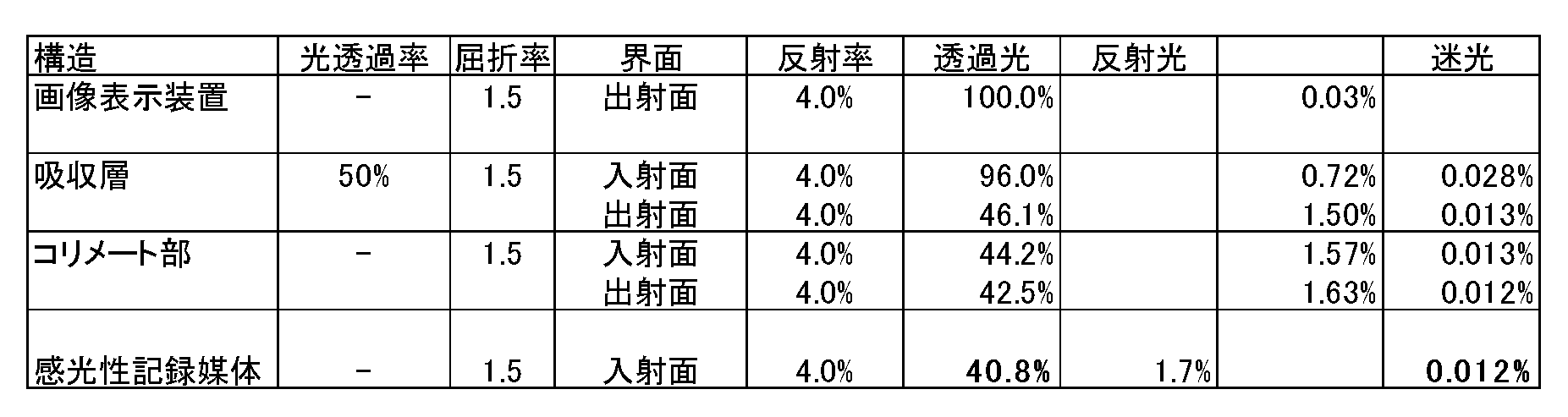
表1を参照して、各数値について説明する。画像表示装置20の出射面20outから100%の光が放射される。100%の光が、吸収層60の入射面60inで4%反射される。96%の光が、吸収層60の入射面60inから吸収層60に入射する。透過光とは、吸収層60、およびコリメート部50に反射されず通過する光を意味している。
吸収層60を通過した96%の光は、吸収層60の出射面60outで4%反射され、さらに吸収層60により50%吸収される。その結果、吸収層60の出射面60outから46.1%の光がコリメート部50に向けて放射される。
46.1%の光が、コリメート部50の入射面50inで4%反射される。44.2%の光が、コリメート部50の入射面50inからコリメート部50に入射する。
コリメート部50を通過した44.2%の光は、コリメート部50の出射面50outで4%反射される。その結果、コリメート部50の出射面50outから42.5%の光が平行光22Aとして感光性記録媒体40に向けて照射される。
最後に、42.5%の光が、感光性記録媒体40の入射面40inで4%反射される。40.8%の光が、感光性記録媒体40の入射面40inからコリメート部50に入射し、感光性記録媒体40を露光する。
一方で、感光性記録媒体40の入射面40inで、42.5%の光の4%に相当する1.7%の光が、反射光として、コリメート部50に向けて放射される。
1.7%の反射光は、コリメート部50の出射面50outで4%反射される。1.63%の反射光が、コリメート部50の出射面50outからコリメート部50に入射する。コリメート部50を通過した1.63%の反射光は、コリメート部50の入射面50inで4%反射される。その結果、コリメート部50の入射面50inから1.57%の反射光が吸収層60に向けて放射される。
1.57%の反射光は、吸収層60の出射面60outで4%反射される。1.50%の反射光が、吸収層60の出射面60outから吸収層60に入射する。吸収層60を通過した1.50%の反射光は、吸収層60の入射面60inで4%反射され、さらに吸収層60により50%吸収される。その結果、吸収層60の入射面60inから0.72%の反射光が画像表示装置20に向けて放射される。
画像表示装置20の出射面20outで、0.72%の反射光の4%に相当する0.03%の光が、迷光として、感光性記録媒体40に向けて放射される。0.03%の迷光は、透過光と同様の光路で、感光性記録媒体40に到達する。
0.03%の迷光は、吸収層60の入射面60in、および出射面60outでそれぞれ4%反射され、かつ50%吸収される。吸収層60の出射面60outから0.013%の迷光が、コリメート部50に向けて放射される。
0.013%の迷光は、コリメート部50の入射面50in、および出射面50outでそれぞれ4%反射される。その結果、コリメート部50の出射面50outから0.012%の反射光が感光性記録媒体40に向けて放射される。
この計算は、空気層を除く全ての媒体の屈折率を1.5とし、それぞれの界面での反射率を4%として計算した。
表1に示されるように、感光性記録媒体40に到達する平行光22Aは、画像表示装置20の出射面20outから放射される100%の光量の光に対して、40.8%の光量の光になる。反射光は、100%の光量の光に対して、1.7%の光量の光になる。
1.7%の反射光は、コリメート部50、吸収層60を通過して、画像表示装置20の出射面20outで反射される。この光量は、100%の光量の光に対して、0.03%の光量の光になる。
少しでも角度をもった平行光でない光は、隣、または、それより離れた感光性記録媒体40に入射することになり、画像のぼけの原因となる迷光になる。
画像表示装置20の画像表示面23に直交する光は、界面で反射等された場合、感光性記録媒体40の同じ位置に到達するので、画像のぼけに対する影響は小さい。しかしながら、この光も迷光の一種ともとらえることができ、その光量が小さい方が好ましい。
画像表示装置20からの光であって感光性記録媒体支持部70に支持された感光性記録媒体40の露光面40Aの位置に直接的に到達する平行光22Aの光量と、画像表示装置20からの光であって感光性記録媒体支持部70に支持された感光性記録媒体40の露光面40Aの位置に間接的に到達する迷光22Bと光量との差が大きくない場合に、画像のぼけとして現れる。平行光22Aの光量と迷光22Bと光量との差は、以下の比で確認することができる。
上述の実施形態において、この反射光は迷光として、吸収層60およびコリメート部50を通過して感光性記録媒体40に到達する。この光量は、100%の光量の光に対して、0.012%の光量の光になる。
したがって、上述の実施形態では、平行光22Aの光量をAとし、迷光22Bの光量をBとしたとき、その比は、B/A=0.012/40.8=1/3466になる。
一般的に、平行光22Aの光量Aと迷光22Bの光量Bとが、B/A≧1/1000の関係にある場合、画像のぼけが生じるとされている。
表1から、50%の光透過率の吸収層60を画像表示装置20と感光性記録媒体40との間に設けることにより、画像のぼけ等の画質の低下を防止できることが理解できる。
表1に示されるように、吸収層60により、感光性記録媒体40の露光面40Aに到達する平行光22Aの光量を50%低減する。一方で、反射光は、吸収層60を2回通過するので、迷光22Bの光量を50%×50%で25%に低減できる。これにより、平行光22Aの光量Aと迷光22Bの光量Bとの比であるB/Aを小さくできる。
次に、画像表示装置20と感光性記録媒体40との間に吸収層60を設けない場合について、画像表示装置20からの光22の中で平行光22A、および迷光22Bが、どの程度の光量で感光性記録媒体40に到達するか計算を行った。表2はその計算結果をまとめたものである。この計算では、空気層の屈折率を1とし、空気層を除く全ての媒体の屈折率を1.5とし、それぞれの界面での反射率を4%として計算した。
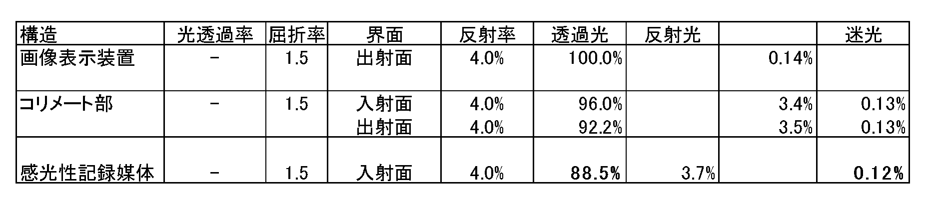
表2に示されるように、感光性記録媒体の露光面に到達する平行光(透過光)は、画像表示装置の出射面から放射される100%の光量の光に対して、88.5%の光量の光になる。反射光は、100%の光量の光に対して、3.7%の光量の光になり、0.12%の光量の光が迷光として感光性記録媒体に到達することが理解できる。
表2の場合、平行光の光量Aと迷光の光量Bとの比は、B/A=0.12/88.5=1/736であり、1/1000以上である。吸収層を設けない場合、画像のぼけが発生するので、感光性記録媒体に形成される画質が低下することが理解できる。
迷光以外にも、コリメート部の入射面および出射面で反射した光、または画像表示装置で戻ってから内部で反射して放射される光などがある。感光性記録媒体に到達した88.5%の平行光以外の11.5%の光が、画像露光装置の内部で迷光となり、感光性記録媒体に到達する懸念がある。
次に、吸収層60が20%の光透過率を有する場合、および10%の光透過率を有する場合について、感光性記録媒体40に到達する平行光22Aと迷光22Bの光量を計算した。表3が光透過率20%の計算結果を示し、表4が光透過率10%の計算結果を示す。
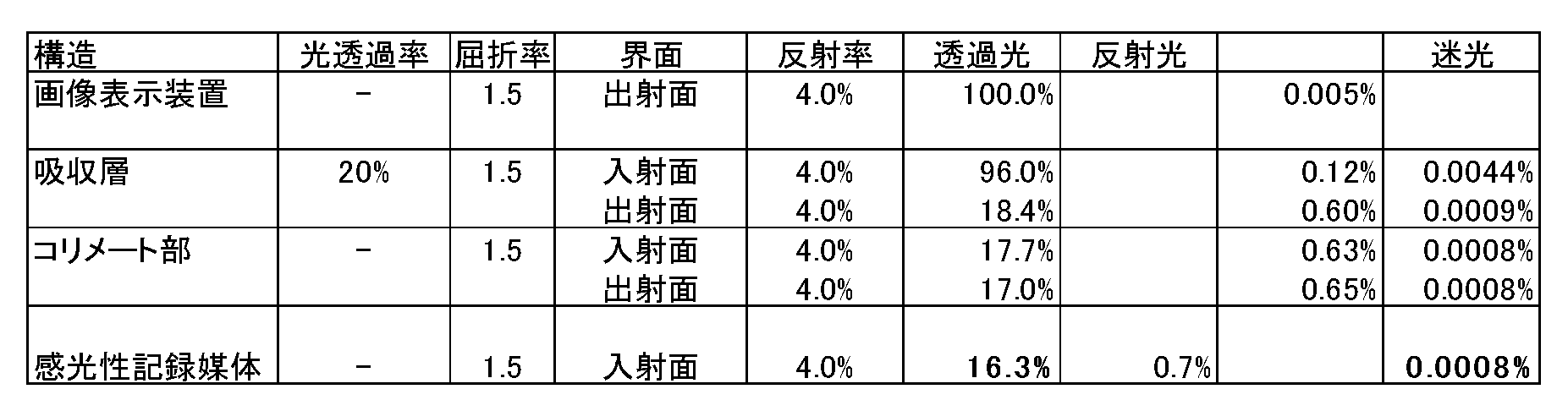
表3の形態の場合、平行光22Aの光量Aと迷光22Bの光量Bとの比は、B/A=0.0008/16.3=1/21660である。
迷光22Bに起因する画像のぼけ等の画質の低下をより確実に抑制するためには、B/A≦1/10000であることが好ましい。吸収層60の光透過率を20%にすることにより、1/10000以下を達成することができる。
なお、吸収層60の光透過率を29%以下とすることにより、B/A≦1/10000を達成することができる。

表4の形態の場合、平行光22Aの光量Aと迷光22Bの光量Bとの比は、B/A=0.0001/8.2=1/86638である。したがって、B/A≦1/10000を十分満たしている。
表4に示されるように、感光性記録媒体40の露光面40Aに到達する平行光22Aは、画像表示装置20からの100%の光に対して、1/10程度の8.2%の光量の光になる。これにより露光時間が延びることになる。一方で、感光性記録媒体40に到達する迷光22Bは、表2に示される0.12%と比較すると1/1000程度の0.0001%の光量の光になる。平行光22Aの光量が8.2%程度であっても、感光性記録媒体40の感度が高いので、平行光22Aにより感光性記録媒体40の露光面40Aを露光することができる。
画像露光装置10を構成する画像表示装置20、吸収層60.コリメート部50、および感光性記録媒体40の特性値(屈折率、吸収率等)から、容易に平行光22Aと迷光22Bと光量の比を求めることができる。
吸収層60の光透過率は小さい方がよく、吸収層60の光透過率は、50%以下、好ましくは40%以下、好ましくは30%以下、より好ましくは20%以下、さらに好ましくは10%以下である。
吸収層60の光透過率は、0.001%以上、好ましくは0.01%以上、より好ましくは0.1%以上、さらに好ましくは0.5%以上である。
透過率が大きすぎる場合、迷光の影響が大きく、画質の低下を抑制することが困難になる。一方、透過率が小さすぎると、露光時間が現実的な長さを超える懸念がある。
次に、画像露光装置10を用いた画像露光方法について説明する。図2は、本発明の露光方法を示すフローチャートである。まず、画像表示装置20を準備する(ステップS11)。次いで、画像表示装置20の画像を記録する感光性記録媒体40を、感光性記録媒体40の露光面40Aを画像表示装置20に対向させて支持する感光性記録媒体支持部70を準備する(ステップS12)。ステップS11の画像表示装置20の準備と、ステップS12の感光性記録媒体支持部70の準備とは、順序に関して、いずれが先であってもよい。
次いで、画像表示装置20からの光を、感光性記録媒体40の露光面40Aに露光する(ステップS13)。ステップS13において、画像表示装置20と感光性記録媒体支持部70との間に配置された、画素からの光を平行光にするコリメート部50と、画素からの光の光透過率が50%以下である吸収層60とを介して、画像表示装置20からの光を、感光性記録媒体40に露光する。
吸収層60が、露光に用いられる画素の波長域の全体を吸収し、透過させる場合について説明した。これに限定されず、吸収層60は、特定の波長域を、他の波長域より吸収し、特定の波長域の透過率を小さくすることができる。
例えば、画像表示装置20の発光スペクトルと感光性記録媒体40の感光スペクトルとに相違がある場合、これを補正するように、波長によって透過率を変えることも可能である。また、コリメート部50などの光学部材に波長によって光透過率が異なる場合には、これを補正することも可能である。
例えば、R(Red)、G(Green)、およびB(Blue)の3波長で露光する場合であり、利用するコリメート部50のBの透過率が50%、GとRの透過率がそれぞれ25%である場合に、吸収層60のBの透過率が10%、GとBの透過率がそれぞれ20%となる条件では、R,G、Bすべての波長の全体の透過率は5%となる。
次に、本発明の好ましい実施形態について説明する。以下の実施形態で、代表的な画像露光装置の構成について説明する。これらの実施形態は、例示の目的のみのためであり、本明細書に記載の画像露光装置を限定することを意味するものではない。
<第1実施形態>
図3は第1実施形態に係る画像露光装置100の分解斜視図であり、図4は第1実施形態に係る画像露光装置100の断面図である。
図3は第1実施形態に係る画像露光装置100の分解斜視図であり、図4は第1実施形態に係る画像露光装置100の断面図である。
図3、図4に示されるように、第1実施形態の画像露光装置100は、画像表示装置110を備える。図3に示されるように、画像表示装置110は二次元状である。二次元状とは、X-Y方向に延びる状態を意味する。第1実施形態では画像表示装置110はX-Y方向に延びている。また、画像表示装置110の複数の画素も二次元状に配列される。
二次元状の画像表示装置110として、例えば、スマートフォン、およびタブレットに代表される携帯端末が適用できる。画像表示装置110は画像を表示することができれば、画像表示方式に限定はなく、LCD方式、OLED方式等の構造が適用できる。画像表示装置は、表面ガラスを除去するのが好ましい。
LCD方式の場合、画像表示装置110は、例えば、光源として機能するバックライトユニット、および画像を表示するためのカラーフィルタを備える複数の画素を備える。複数の画素を保護するため、画像表示装置110は筐体および表面ガラス等を備えることが好ましい。
図3、4に示されるように、画像露光装置100は、吸収層を構成するNDフィルタ120を備える。吸収層を構成するNDフィルタ120が、画像表示装置110の画像表示面の側に設けられる。NDフィルタ120として、富士フイルム株式会社製の写真露光用の光量調整用フィルタを用いることができる。株式会社ケンコー・トキナ、コダックおよびシグマ光機株式会社等から販売されているNDフィルタを用いることができる。
50%以上の透過率を得るため、0.3以上の光学濃度(OD)を有するNDフィルタ120が、好ましくは用いられる。NDフィルタ120は、例えば、90μm±10μmの厚さを有する。NDフィルタ120の厚さは、この範囲には限定されない。NDフィルタ120は、画像表示装置110の画像表示面の全域を覆うことが好ましい。
図3、4に示されるように、画像露光装置100は、コリメート部としてファイバーオプティックプレート130を備える。ファイバーオプティックプレート130は、光ファイバーに入射された光を全反射して伝送する。ファイバーオプティックプレート130の光ファイバーのピッチは、画像表示装置110の画素ピッチ以下であることが好ましい。
ファイバーオプティックプレート130は、画像表示装置110の画像表示面の全域を覆うことが好ましい。
図3、4に示されるように、画像露光装置100は、感光性記録媒体を構成するインスタントフィルム142と、インスタントフィルム142を収納するケース144とから構成されるフィルムパック140を備える。フィルムパック140を支持するための感光性記録媒体支持部である筐体148を備える。筐体148はフィルムパック140を着脱自在に支持することができる。
ケース144は、複数のインスタントフィルム142を収納することができる。図4に示されるように、ケース144、及び筐体148には、画像表示装置110に対向する側に、開口部146が形成されている。
インスタントフィルム142は矩形のカード形状を有する。インスタントフィルム142は、裏面側が露光面142A、正面側が観察面142Bとして構成される。露光面142Aが、平行光による露光により像を記録する面であり、観察面142Bが、記録された像を観察する面である。
インスタントフィルム142の露光面142Aには、露光部と、露光部を挟んでポッド部とトラップ部とを有する(不図示)。ポッド部には現像処理液を内包した現像処理液ポッドが内蔵されている。トラップ部には吸収剤が内蔵される。
インスタントフィルム142は、露光後、ポッド部の現像処理液を露光部に展開させることにより現像処理される。ポッド部の現像処理液は、インスタントフィルム142をローラー対(不図示)の間に通すことで、ポッド部から絞り出され、露光部に展開される。展開処理時に余った現像処理液が、トラップ部で捕捉される。
第1実施形態では画像表示装置110がX-Y方向に延びる二次元状に配列さえた画素を有する。画像表示装置110の画像表示面は、NDフィルタ120と、ファイバーオプティックプレート130と、インスタントフィルム142の二次元状の露光面の大きさと略同じである。したがって、画像表示装置110からの画像を、インスタントフィルム142の露光面の二次元状の全ての領域を同時に露光することができる。
露光したい画像を画像表示装置110に表示させる。画像表示装置110の画素からの光は、NDフィルタ120およびファイバーオプティックプレート130を通過し平行光になる。この平行光がインスタントフィルム142の露光面142Aに到達し、インスタントフィルム142を同時に露光することができる。露光面の二次元状の全ての領域を同時に露光する態様として、例えば、1次元状に画素が配列された画像表示装置を、複数並べて二次元状とし、同時に露光する場合でもよい。
一方で、NDフィルタ120は、インスタントフィルム142に露光面142Aに到達する迷光を大幅に低減する。露光後、現像処理がインスタントフィルム142に行われる。インスタントフィルム142には、画像ぼけのほとんどない、画像が形成され、画質の低下が抑制されることが、上述した原理から容易に理解できる。
なお、画像表示装置110が画像を表示する時間を制御することで、画像表示装置110はシャッターの機構を持つことができる。また、画像表示装置110とインスタントフィルム142との間に、シャッター機構を設けることもできる。
画像表示装置110が携帯端末である場合、画像表示装置110は、画像露光装置100に対して着脱自在であることが好ましい。着脱自在とは、取り付け、取り外しできることを意味する。例えば、画像表示装置110の使用者が、画像表示装置110により画像を取得する。画像表示装置110を画像露光装置100の一部の構成として取り付ける。画像表示装置110の画像により、インスタントフィルム142を露光する。露光後、画像露光装置100から画像表示装置110を取り出し、画像表示装置110により新たな画像を取得することができる。
<第2実施形態>
第2実施形態について図5を参照して説明する。なお、上述した第1実施形態と同一の作用を奏する部分には、同一の符号を付することによりその部分の詳細な説明を省略し、主に他の実施形態と異なる点を説明する。
第2実施形態について図5を参照して説明する。なお、上述した第1実施形態と同一の作用を奏する部分には、同一の符号を付することによりその部分の詳細な説明を省略し、主に他の実施形態と異なる点を説明する。
図5に示されるように、画像露光装置100は、画像表示装置110と、NDフィルタ120と、ファイバーオプティックプレート130と、複数のインスタントフィルム(不図示)を収納するケース144で構成されるフィルムパック140と、備える。
第1実施形態と異なり、第2実施形態の画像表示装置110は、一次元状である。一次元とは、X-Y方向の一方の方向に延びる状態を意味する。図5に示されるように、画像表示装置110はX方向に延びている。画像表示装置110は、一次元状に配列された画素を有している。
画像表示装置110は、インスタントフィルムのX方向とほぼ同じ長さである。一方で、画像表示装置110は一次元であるので、画像表示装置110のY方向の長さは、インスタントフィルムのY方向の長さより短い。画像表示装置110はインスタントフィルムの露光面より小さいことになる。
第2実施形態では、インスタントフィルムを露光するため、画像表示装置110は、画素の配列方向であるX方向に対して垂直方向であるY方向に沿って走査される。
図5に示されるように、画像露光装置100は、画像表示装置110を走査するための走査部200を備える。走査部200は、画像表示装置110の両端を支持する支持部210と、フィルムパック140を支持する支持台220と、支持台220に内蔵される駆動部(不図示)と、を備える。支持台220はレール250を備え、駆動部は支持部210をレール250に沿ってY方向に走査することができる。
走査部200が画像表示装置110を垂直方向に走査しながら、画像表示装置110はインスタントフィルムを順次露光することができる。画像表示装置110の画像表示と、走査部200の駆動とを、同期させるため不図示の制御部を備えることが好ましい。
画像表示装置110の画素からの光は、NDフィルタ120およびファイバーオプティックプレート130を通過し平行光になる。この平行光がインスタントフィルム142の露光面142Aに到達し、インスタントフィルム142を順次露光することができる。
NDフィルタ120は、インスタントフィルム142の露光面142Aに到達する迷光を大幅に低減する。露光後、現像処理がインスタントフィルム142に行われる。インスタントフィルム142には、画像ぼけのほとんどない、画像が形成され、画質の低下が抑制されることは、上述した原理から容易に理解できる。
図6は第2実施形態の画像露光装置100の変形例を示す。変形例の画像露光装置100は、画像表示装置110と、NDフィルタ120と、ファイバーオプティックプレート130と、インスタントフィルム142を収納するケース144で構成されるフィルムパック140を着脱自在に支持する筐体148と、備える。
変形例の画像露光装置100では、NDフィルタ120と、ファイバーオプティックプレート130とが、画像表示装置110の画素の配列方向と同様にX方向に延びる一次元状で構成される。
走査部200は、画像表示装置110と、NDフィルタ120と、ファイバーオプティックプレート130とを、画像表示装置110の画素の配列方向に対して垂直方向に沿って走査しながら、画像表示装置110はインスタントフィルム142を順次露光することができる。
画像表示装置110の画素からの光は、NDフィルタ120およびファイバーオプティックプレート130を通過し平行光になる。この平行光がインスタントフィルム142に到達し、インスタントフィルム142の露光面142Aを順次露光することができる。
NDフィルタ120は、インスタントフィルム142の露光面142Aに到達する迷光を大幅に低減する。露光後、現像処理がインスタントフィルム142に行われる。インスタントフィルム142には、画像ぼけのほとんどない、画像が形成され、画質の低下が抑制されることは、上述した原理から容易に理解できる。
画像表示装置110を走査しながら露光する場合を説明したが、画像表示装置110とインスタントフィルム142とが相対的に走査できれば、インスタントフィルムを走査しながら露光してもよい。すなわち、画像表示装置110及びインスタントフィルム142の少なくとも一方を走査させればよい。
<第3実施形態>
第3実施形態について図7を参照して説明する。なお、上述した第1実施形態および第2実施形態と同一の作用を奏する部分には、同一の符号を付することによりその部分の詳細な説明を省略し、主に他の実施形態と異なる点を説明する。
第3実施形態について図7を参照して説明する。なお、上述した第1実施形態および第2実施形態と同一の作用を奏する部分には、同一の符号を付することによりその部分の詳細な説明を省略し、主に他の実施形態と異なる点を説明する。
図7に示されるように、画像露光装置100は、画像表示装置110と、NDフィルタ120と、ファイバーオプティックプレート130と、複数のインスタントフィルム(不図示)を収納するケース144で構成されるフィルムパック140を着脱自在に支持する筐体148と、走査部200と、を備える。
第1実施形態と異なり、第3実施形態の画像表示装置110は、二次元状である。また、画像表示装置110は感光性記録媒体であるインスタントフィルムの露光面より小さい面積となる領域の上に二次元状に配列された画素を有している。複数の画素は、例えば、行列状に二次元状に配列されることが好ましい。
インスタントフィルムを露光するため、第2実施形態と同様に、第3実施形態は、走査部200を備える。一方で、第2実施形態と異なり、第3実施形態の走査部200は、画像表示装置110をY方向に走査するだけでなく、X方向にも走査することができる。
例えば、行列状に二次元状に配列された画素では、行方方向をX方向とした場合、行方向(X方向)と行方向(X方向)に対して垂直となる方向(Y方向)の両方向に沿って、走査部を走査させることが好ましい。
したがって、走査部200は、ボールネジ230と、ボールネジ230に係合するナットを備える移動部240と、を備える。ボールネジ230の回転運動により、移動部240はX方向に移動できる。移動部240は、画像表示装置110を保持するための保持部(不図示)を有することが好ましい。
走査部200が画像表示装置110をX方向とY方向とに走査しながら、画像表示装置110はインスタントフィルムを順次露光することができる。画像表示装置110の画像表示と、走査部200の駆動とを、同期させるため不図示の制御部を備えることが好ましい。
第3実施形態では、画像表示装置110より大きな露光面を有する感光性記録媒体に露光する場合に有効に適用することができる。
画像表示装置110の画素からの光は、NDフィルタ120およびファイバーオプティックプレート130を通過し平行光になる。この平行光がインスタントフィルム142に到達し、インスタントフィルム142を順次露光することができる。
NDフィルタ120は、インスタントフィルム142に到達する迷光を大幅に低減する。露光後、現像処理がインスタントフィルム142に行われる。インスタントフィルム142には、画像ぼけのほとんどない、画像が形成され、画質の低下が抑制されることは、上述した原理から容易に理解できる。
図8は第3実施形態の画像露光装置100の変形例を示す。変形例の画像露光装置100は、画像表示装置110と、NDフィルタ120と、ファイバーオプティックプレート130と、インスタントフィルム142を収納するケース144で構成されるフィルムパック140を着脱自在に支持する筐体148と、走査部200と、を備える。
変形例の画像露光装置100では、NDフィルタ120と、ファイバーオプティックプレート130とが、画像表示装置110と同様に感光性記録媒体であるインスタントフィルム142より小さい二次元状である。
走査部200が、画像表示装置110と、NDフィルタ120と、ファイバーオプティックプレート130と、をX方向とY方向とに走査しながら、画像表示装置110はインスタントフィルム142を順次露光することができる。画像表示装置110の画像表示と、走査部200の駆動とを、同期させるため不図示の制御部を備えることが好ましい。
画像表示装置110の画素からの光は、NDフィルタ120およびファイバーオプティックプレート130を通過し平行光になる。この平行光がインスタントフィルム142の露光面142Aに到達し、インスタントフィルム142を順次露光することができる。
NDフィルタ120は、インスタントフィルム142の露光面142Aに到達する迷光を大幅に低減する。露光後、インスタントフィルム142に現像処理が行われる。インスタントフィルム142には、画像ぼけのほとんどない、画像が形成され、画質の低下が抑制されることは、上述した原理から容易に理解できる。
画像表示装置110をX方向とY方向とに走査しながら露光する場合を説明したが、画像表示装置110とインスタントフィルム142とが相対的に走査できれば、インスタントフィルムをX方向とY方向とに走査しながら、露光してもよい。すなわち、画像表示装置110及びインスタントフィルム142の少なくとも一方をX方向とY方向の両方向に沿って走査させればよい。
第2実施形態と第3実施形態では、画像表示装置が感光性記録媒体より小さい。画像表示装置の画素からの光による露光範囲において、隣り合う露光範囲が一部重複してもよい。露光範囲の一部を重複させない場合、感光性記録媒体の上に未露光領域が発生する懸念がある。未露光領域に起因する感光性記録媒体に画像が形成されない状態を回避することが好ましい。
10 画像露光装置
20 画像表示装置
20out 出射面
21 画素
22 光
22A 平行光
22B 迷光
23 画像表示面
40 感光性記録媒体
40A 露光面
40in 入射面
50 コリメート部
50in 入射面
50out 出射面
60 吸収層
60in 入射面
60out 出射面
70 感光性記録媒体支持部
100 画像露光装置
110 画像表示装置
120 NDフィルタ
130 ファイバーオプティックプレート
140 フィルムパック
142 インスタントフィルム
142A 露光面
142B 観察面
144 ケース
146 開口部
148 筐体
200 走査部
210 支持部
220 支持台
230 ボールネジ
240 移動部
250 レール
20 画像表示装置
20out 出射面
21 画素
22 光
22A 平行光
22B 迷光
23 画像表示面
40 感光性記録媒体
40A 露光面
40in 入射面
50 コリメート部
50in 入射面
50out 出射面
60 吸収層
60in 入射面
60out 出射面
70 感光性記録媒体支持部
100 画像露光装置
110 画像表示装置
120 NDフィルタ
130 ファイバーオプティックプレート
140 フィルムパック
142 インスタントフィルム
142A 露光面
142B 観察面
144 ケース
146 開口部
148 筐体
200 走査部
210 支持部
220 支持台
230 ボールネジ
240 移動部
250 レール
Claims (12)
- 画素を有する画像表示装置と、
前記画像表示装置の画像を記録する感光性記録媒体を、前記感光性記録媒体の露光面を前記画像表示装置に対向させて支持する感光性記録媒体支持部と、
前記画像表示装置と前記感光性記録媒体支持部との間に設けられ、前記画素からの光を平行光にするコリメート部と、
前記画像表示装置と前記感光性記録媒体支持部との間に設けられ、前記画素からの光の光透過率が50%以下である吸収層と、
を備える画像露光装置。 - 前記吸収層が、ニュートラルデンシティーフィルタである請求項1に記載の画像露光装置。
- 前記コリメート部が、スリット、ファイバーオプティックプレート、キャピラリプレート、及び、複数の開口を有する透過部材を3層以上積層してなる光制御部から選ばれる少なくとも1つである請求項1又は2に記載の画像露光装置。
- 前記吸収層の光透過率が、20%以下である請求項1から3のいずれか1項に記載の画像露光装置。
- 前記吸収層の光透過率が、0.001%以上である請求項1から4のいずれか1項に記載の画像露光装置。
- 前記画像表示装置から前記感光性記録媒体支持部に支持された前記感光性記録媒体の前記露光面の位置に直接的に到達する光量をA、前記画像表示装置から前記感光性記録媒体の前記露光面の位置に間接的に到達する光量をBとしたとき、B/Aが1/10000以下である請求項1から5のいずれか1項に記載の画像露光装置。
- 前記画像表示装置が二次元状に配列された画素を有し、
前記感光性記録媒体の前記露光面の二次元状の全ての領域を同時に露光する請求項1から6のいずれか1項に記載の画像露光装置。 - 前記画像表示装置が一次元状に配列された前記画素を有し、
前記画像表示装置及び前記感光性記録媒体支持部に支持された前記感光性記録媒体の少なくともいずれか一方を、前記画像表示装置の前記画素の配列方向に対して垂直となる方向に沿って走査する走査部と、を備える請求項1から6のいずれか1項に記載の画像露光装置。 - 前記画像表示装置が、前記感光性記録媒体の前記露光面より小さい面積となる領域の上に二次元状に配列された画素を有し、
前記画像表示装置及び前記感光性記録媒体支持部に支持された前記感光性記録媒体の少なくともいずれか一方を前記画像表示装置の前記画素の配列方向と前記画素の配列方向に対して垂直となる方向の両方に沿って走査する走査部を備える請求項1から6のいずれか1項に記載の画像露光装置。 - 前記画素からの光による露光範囲において、隣り合う前記露光範囲が一部重複する請求項8又は9に記載の画像露光装置。
- 前記画像表示装置が、着脱自在である請求項1から10の何れか1項に記載の画像露光装置。
- 画素を有する画像表示装置を準備するステップと、
前記画像表示装置の画像を記録する感光性記録媒体を、前記感光性記録媒体の露光面を前記画像表示装置に対向させて支持する感光性記録媒体支持部を準備するステップと、
前記画像表示装置と前記感光性記録媒体支持部との間に配置された、前記画素からの光を平行光にするコリメート部と、前記画素からの光の光透過率が50%以下である吸収層とを介して、前記画像表示装置からの光を、前記感光性記録媒体に露光するステップと、
を含む画像露光方法。
Priority Applications (4)
| Application Number | Priority Date | Filing Date | Title |
|---|---|---|---|
| JP2019543638A JP6869363B2 (ja) | 2017-09-21 | 2018-09-18 | 画像露光装置、および画像露光方法 |
| DE112018005371.7T DE112018005371B4 (de) | 2017-09-21 | 2018-09-18 | Bildbelichtungsvorrichtung und bildbelichtungsverfahren |
| CN201880061365.1A CN111108439B (zh) | 2017-09-21 | 2018-09-18 | 图像曝光装置及图像曝光方法 |
| US16/807,325 US10739681B2 (en) | 2017-09-21 | 2020-03-03 | Image exposure device and image exposure method |
Applications Claiming Priority (2)
| Application Number | Priority Date | Filing Date | Title |
|---|---|---|---|
| JP2017181422 | 2017-09-21 | ||
| JP2017-181422 | 2017-09-21 |
Related Child Applications (1)
| Application Number | Title | Priority Date | Filing Date |
|---|---|---|---|
| US16/807,325 Continuation US10739681B2 (en) | 2017-09-21 | 2020-03-03 | Image exposure device and image exposure method |
Publications (1)
| Publication Number | Publication Date |
|---|---|
| WO2019059176A1 true WO2019059176A1 (ja) | 2019-03-28 |
Family
ID=65809803
Family Applications (1)
| Application Number | Title | Priority Date | Filing Date |
|---|---|---|---|
| PCT/JP2018/034459 Ceased WO2019059176A1 (ja) | 2017-09-21 | 2018-09-18 | 画像露光装置、および画像露光方法 |
Country Status (6)
| Country | Link |
|---|---|
| US (1) | US10739681B2 (ja) |
| JP (1) | JP6869363B2 (ja) |
| CN (1) | CN111108439B (ja) |
| DE (1) | DE112018005371B4 (ja) |
| TW (1) | TWI769315B (ja) |
| WO (1) | WO2019059176A1 (ja) |
Cited By (2)
| Publication number | Priority date | Publication date | Assignee | Title |
|---|---|---|---|---|
| US20200238684A1 (en) * | 2017-11-07 | 2020-07-30 | Fujifilm Corporation | Image exposure device |
| US11169451B2 (en) * | 2017-11-07 | 2021-11-09 | Fujifilm Corporation | Image exposure device and image exposure method |
Families Citing this family (1)
| Publication number | Priority date | Publication date | Assignee | Title |
|---|---|---|---|---|
| WO2019059168A1 (ja) * | 2017-09-22 | 2019-03-28 | 富士フイルム株式会社 | 画像露光装置 |
Citations (9)
| Publication number | Priority date | Publication date | Assignee | Title |
|---|---|---|---|---|
| JPH10104752A (ja) * | 1996-08-05 | 1998-04-24 | Victor Co Of Japan Ltd | プリンタ装置 |
| JPH10309829A (ja) * | 1997-04-08 | 1998-11-24 | Eastman Kodak Co | 可変濃度画素印刷装置 |
| JP2000075243A (ja) * | 1998-08-31 | 2000-03-14 | Citizen Watch Co Ltd | 立体表示装置 |
| JP2001045342A (ja) * | 1999-08-02 | 2001-02-16 | Nippon Polaroid Kk | 画像表示機能を備える露光装置、露光機能を備える電子カメラ、情報端末および携帯通信装置 |
| JP2002341459A (ja) * | 2001-05-17 | 2002-11-27 | Mitsubishi Electric Corp | 表示装置およびプリント装置 |
| JP2003015087A (ja) * | 2001-07-02 | 2003-01-15 | Fuji Photo Film Co Ltd | 偏光方向制御素子及び露光装置 |
| JP2003162007A (ja) * | 2001-11-28 | 2003-06-06 | Fuji Photo Film Co Ltd | 転写装置 |
| JP2004291298A (ja) * | 2003-03-26 | 2004-10-21 | Fuji Photo Film Co Ltd | 表示装置 |
| US9126396B2 (en) * | 2013-11-21 | 2015-09-08 | Pacific Opal LLC | Instant film printer for light emitting display screen incorporating optical collimation layer |
Family Cites Families (6)
| Publication number | Priority date | Publication date | Assignee | Title |
|---|---|---|---|---|
| JPH02228629A (ja) * | 1989-02-28 | 1990-09-11 | Sharp Corp | 液晶表示装置 |
| JP2001116917A (ja) * | 1999-10-18 | 2001-04-27 | Hitachi Ltd | 画像品位向上部材及びこれを用いた画像表示装置 |
| US7643048B2 (en) * | 2001-11-06 | 2010-01-05 | Fujifilm Corporation | Image transfer apparatus |
| JP2004160784A (ja) * | 2002-11-12 | 2004-06-10 | Fuji Photo Film Co Ltd | 転写装置 |
| KR100983582B1 (ko) * | 2007-12-31 | 2010-10-11 | 엘지디스플레이 주식회사 | 노광 장치 및 노광 방법과 그 노광 장치를 이용한 박막패터닝 방법 |
| US8467177B2 (en) * | 2010-10-29 | 2013-06-18 | Apple Inc. | Displays with polarizer windows and opaque masking layers for electronic devices |
-
2018
- 2018-09-18 WO PCT/JP2018/034459 patent/WO2019059176A1/ja not_active Ceased
- 2018-09-18 CN CN201880061365.1A patent/CN111108439B/zh active Active
- 2018-09-18 JP JP2019543638A patent/JP6869363B2/ja active Active
- 2018-09-18 DE DE112018005371.7T patent/DE112018005371B4/de active Active
- 2018-09-21 TW TW107133370A patent/TWI769315B/zh active
-
2020
- 2020-03-03 US US16/807,325 patent/US10739681B2/en active Active
Patent Citations (9)
| Publication number | Priority date | Publication date | Assignee | Title |
|---|---|---|---|---|
| JPH10104752A (ja) * | 1996-08-05 | 1998-04-24 | Victor Co Of Japan Ltd | プリンタ装置 |
| JPH10309829A (ja) * | 1997-04-08 | 1998-11-24 | Eastman Kodak Co | 可変濃度画素印刷装置 |
| JP2000075243A (ja) * | 1998-08-31 | 2000-03-14 | Citizen Watch Co Ltd | 立体表示装置 |
| JP2001045342A (ja) * | 1999-08-02 | 2001-02-16 | Nippon Polaroid Kk | 画像表示機能を備える露光装置、露光機能を備える電子カメラ、情報端末および携帯通信装置 |
| JP2002341459A (ja) * | 2001-05-17 | 2002-11-27 | Mitsubishi Electric Corp | 表示装置およびプリント装置 |
| JP2003015087A (ja) * | 2001-07-02 | 2003-01-15 | Fuji Photo Film Co Ltd | 偏光方向制御素子及び露光装置 |
| JP2003162007A (ja) * | 2001-11-28 | 2003-06-06 | Fuji Photo Film Co Ltd | 転写装置 |
| JP2004291298A (ja) * | 2003-03-26 | 2004-10-21 | Fuji Photo Film Co Ltd | 表示装置 |
| US9126396B2 (en) * | 2013-11-21 | 2015-09-08 | Pacific Opal LLC | Instant film printer for light emitting display screen incorporating optical collimation layer |
Cited By (3)
| Publication number | Priority date | Publication date | Assignee | Title |
|---|---|---|---|---|
| US20200238684A1 (en) * | 2017-11-07 | 2020-07-30 | Fujifilm Corporation | Image exposure device |
| US10857783B2 (en) * | 2017-11-07 | 2020-12-08 | Fujifilm Corporation | Image exposure device |
| US11169451B2 (en) * | 2017-11-07 | 2021-11-09 | Fujifilm Corporation | Image exposure device and image exposure method |
Also Published As
| Publication number | Publication date |
|---|---|
| JPWO2019059176A1 (ja) | 2020-11-05 |
| CN111108439A (zh) | 2020-05-05 |
| DE112018005371T5 (de) | 2020-08-06 |
| CN111108439B (zh) | 2021-04-16 |
| US20200201187A1 (en) | 2020-06-25 |
| US10739681B2 (en) | 2020-08-11 |
| TWI769315B (zh) | 2022-07-01 |
| TW201923440A (zh) | 2019-06-16 |
| JP6869363B2 (ja) | 2021-05-12 |
| DE112018005371B4 (de) | 2023-09-28 |
Similar Documents
| Publication | Publication Date | Title |
|---|---|---|
| US8366281B2 (en) | Out-of-plane motion of speckle reduction element | |
| EP2433173B1 (en) | Optical projection system with curved speckle reduction element surface | |
| US20040150883A1 (en) | Projection screen and manufacturing method thereof | |
| US11361412B2 (en) | Image exposure device, image exposure method, and program | |
| US10857783B2 (en) | Image exposure device | |
| EP2433175A2 (en) | Projection with lenslet arrangement on speckle reduction element | |
| JP6869363B2 (ja) | 画像露光装置、および画像露光方法 | |
| JP6937379B2 (ja) | 画像露光装置 | |
| US11169451B2 (en) | Image exposure device and image exposure method | |
| JP7321296B2 (ja) | 情報処理方法 | |
| US20100296063A1 (en) | Projection with larger intermediate image | |
| JP2001201795A (ja) | 画像焼付装置およびこれを備えた写真処理装置 | |
| JP2017146348A (ja) | 露光装置 |
Legal Events
| Date | Code | Title | Description |
|---|---|---|---|
| 121 | Ep: the epo has been informed by wipo that ep was designated in this application |
Ref document number: 18857618 Country of ref document: EP Kind code of ref document: A1 |
|
| ENP | Entry into the national phase |
Ref document number: 2019543638 Country of ref document: JP Kind code of ref document: A |
|
| NENP | Non-entry into the national phase |
Ref country code: DE |
|
| 122 | Ep: pct application non-entry in european phase |
Ref document number: 18857618 Country of ref document: EP Kind code of ref document: A1 |