WO2019059373A1 - Machine de transport frigorifique - Google Patents
Machine de transport frigorifique Download PDFInfo
- Publication number
- WO2019059373A1 WO2019059373A1 PCT/JP2018/035181 JP2018035181W WO2019059373A1 WO 2019059373 A1 WO2019059373 A1 WO 2019059373A1 JP 2018035181 W JP2018035181 W JP 2018035181W WO 2019059373 A1 WO2019059373 A1 WO 2019059373A1
- Authority
- WO
- WIPO (PCT)
- Prior art keywords
- compressor
- vibration
- spring constant
- elastic body
- rubber
- Prior art date
- Legal status (The legal status is an assumption and is not a legal conclusion. Google has not performed a legal analysis and makes no representation as to the accuracy of the status listed.)
- Ceased
Links
Images


Classifications
-
- F—MECHANICAL ENGINEERING; LIGHTING; HEATING; WEAPONS; BLASTING
- F04—POSITIVE - DISPLACEMENT MACHINES FOR LIQUIDS; PUMPS FOR LIQUIDS OR ELASTIC FLUIDS
- F04B—POSITIVE-DISPLACEMENT MACHINES FOR LIQUIDS; PUMPS
- F04B39/00—Component parts, details, or accessories, of pumps or pumping systems specially adapted for elastic fluids, not otherwise provided for in, or of interest apart from, groups F04B25/00 - F04B37/00
- F04B39/0027—Pulsation and noise damping means
- F04B39/0044—Pulsation and noise damping means with vibration damping supports
-
- F—MECHANICAL ENGINEERING; LIGHTING; HEATING; WEAPONS; BLASTING
- F01—MACHINES OR ENGINES IN GENERAL; ENGINE PLANTS IN GENERAL; STEAM ENGINES
- F01C—ROTARY-PISTON OR OSCILLATING-PISTON MACHINES OR ENGINES
- F01C21/00—Component parts, details or accessories not provided for in groups F01C1/00 - F01C20/00
- F01C21/007—General arrangements of parts; Frames and supporting elements
-
- F—MECHANICAL ENGINEERING; LIGHTING; HEATING; WEAPONS; BLASTING
- F04—POSITIVE - DISPLACEMENT MACHINES FOR LIQUIDS; PUMPS FOR LIQUIDS OR ELASTIC FLUIDS
- F04B—POSITIVE-DISPLACEMENT MACHINES FOR LIQUIDS; PUMPS
- F04B39/00—Component parts, details, or accessories, of pumps or pumping systems specially adapted for elastic fluids, not otherwise provided for in, or of interest apart from, groups F04B25/00 - F04B37/00
-
- F—MECHANICAL ENGINEERING; LIGHTING; HEATING; WEAPONS; BLASTING
- F04—POSITIVE - DISPLACEMENT MACHINES FOR LIQUIDS; PUMPS FOR LIQUIDS OR ELASTIC FLUIDS
- F04B—POSITIVE-DISPLACEMENT MACHINES FOR LIQUIDS; PUMPS
- F04B39/00—Component parts, details, or accessories, of pumps or pumping systems specially adapted for elastic fluids, not otherwise provided for in, or of interest apart from, groups F04B25/00 - F04B37/00
- F04B39/14—Provisions for readily assembling or disassembling
-
- B—PERFORMING OPERATIONS; TRANSPORTING
- B60—VEHICLES IN GENERAL
- B60P—VEHICLES ADAPTED FOR LOAD TRANSPORTATION OR TO TRANSPORT, TO CARRY, OR TO COMPRISE SPECIAL LOADS OR OBJECTS
- B60P3/00—Vehicles adapted to transport, to carry or to comprise special loads or objects
- B60P3/20—Refrigerated goods vehicles
-
- F—MECHANICAL ENGINEERING; LIGHTING; HEATING; WEAPONS; BLASTING
- F04—POSITIVE - DISPLACEMENT MACHINES FOR LIQUIDS; PUMPS FOR LIQUIDS OR ELASTIC FLUIDS
- F04C—ROTARY-PISTON, OR OSCILLATING-PISTON, POSITIVE-DISPLACEMENT MACHINES FOR LIQUIDS; ROTARY-PISTON, OR OSCILLATING-PISTON, POSITIVE-DISPLACEMENT PUMPS
- F04C18/00—Rotary-piston pumps specially adapted for elastic fluids
- F04C18/02—Rotary-piston pumps specially adapted for elastic fluids of arcuate-engagement type, i.e. with circular translatory movement of co-operating members, each member having the same number of teeth or tooth-equivalents
- F04C18/0207—Rotary-piston pumps specially adapted for elastic fluids of arcuate-engagement type, i.e. with circular translatory movement of co-operating members, each member having the same number of teeth or tooth-equivalents both members having co-operating elements in spiral form
-
- F—MECHANICAL ENGINEERING; LIGHTING; HEATING; WEAPONS; BLASTING
- F04—POSITIVE - DISPLACEMENT MACHINES FOR LIQUIDS; PUMPS FOR LIQUIDS OR ELASTIC FLUIDS
- F04C—ROTARY-PISTON, OR OSCILLATING-PISTON, POSITIVE-DISPLACEMENT MACHINES FOR LIQUIDS; ROTARY-PISTON, OR OSCILLATING-PISTON, POSITIVE-DISPLACEMENT PUMPS
- F04C2270/00—Control; Monitoring or safety arrangements
- F04C2270/12—Vibration
Definitions
- the present invention relates to a transport refrigerator.
- the vehicle is equipped with a compressor for compressing the refrigerant.
- the compressor is supported on the bracket in a predetermined attitude.
- a plurality of support legs are provided at the lower portion of the compressor and fixed to the bracket, and a plurality of flanges are provided at the upper portion of the compressor and fixed to the bracket.
- Each flange is fixed to the bracket via an elastic body so as to suppress transmission of vibration accompanying driving of the compressor to the bracket.
- the present invention has been made in view of such circumstances, and it is an object of the present invention to provide a transport refrigerator that supports a compressor so as to have vibration isolation performance and fixed strength against traveling vibration. .
- a transport refrigerator includes a compressor for compressing a refrigerant for cooling a transport container installed in a vehicle, and a main body below the center of gravity of the compressor supported by the main body
- a lower elastic support member having a lower elastic body, and an upper antivibration support member having an upper elastic body and supporting the upper portion above the center of gravity of the compressor with respect to the main body
- the spring constant of is larger than the spring constant of the lower elastic body.
- the upper anti-vibration support member While supporting the lower side of the center of gravity of the compressor with respect to the main body by the lower anti-vibration support member, the upper anti-vibration support member supports the upper side of the center of gravity of the compressor with respect to the main body We decided to support both ends of the center of gravity. Thereby, the vibration displacement of the compressor can be suppressed in various vibration directions.
- the spring constant of the upper elastic body of the upper vibration isolation support member larger than the spring constant of the lower elastic body of the lower vibration isolation support member, the vibration displacement of the upper portion of the compressor is relative to the lower portion of the compressor Can be made smaller.
- the upper elastic body and the lower elastic body for example, anti-vibration rubber can be used.
- the transport refrigerator includes a pipe connected to an upper portion of the compressor.
- piping is connected to the upper part of the compressor, it may be vibrated and damaged by vibration transmission from the compressor.
- the vibration displacement of the upper part of the compressor is suppressed, breakage of the piping Can be reduced.
- discharge piping, gas injection piping, and the like having a smaller pipe diameter than the suction piping and the like are connected to the upper portion of the compressor, which is effective.
- the upper portion of the compressor is, for example, above the center of gravity of the compressor.
- the upper anti-vibration support member includes a band provided on the outer periphery of the compressor, and the upper elastic body provided between the band and the main body or the band and the compressor. It is good.
- the spring constant of the upper elastic body is set to be a natural frequency larger than a representative frequency representing the traveling time of the vehicle.
- the spring constant of the upper elastic body is set to be larger than the representative frequency representing the traveling time of the vehicle, it is possible that the upper portion of the compressor is largely vibrated by the vibration transmission during the traveling of the vehicle. It can be prevented.
- working of a vehicle the value defined by standards, such as a Japanese Industrial Standard (JIS), is used, for example, 20 Hz is mentioned.
- the spring constant of the lower elastic body is set to be a natural frequency larger than the representative frequency.
- the spring constant of the lower elastic body is set to be the natural frequency larger than the representative frequency, the vibration of the compressor can be further suppressed.
- the spring constant of the upper elastic body above the center of gravity of the compressor is made larger than the spring constant of the lower elastic body below the center of gravity of the compressor, it has anti-vibration performance and fixed strength against traveling vibration
- the compressor can be supported.
- the refrigerator car 1 includes a container (transport container) 3 in the vehicle 2.
- a transport refrigerator 5 is provided in front of the container 3 and above the cab 4.
- the transport refrigerator 5 includes a compressor, a condenser, an expansion valve, and an evaporator that constitute a refrigeration cycle. Inside the housing 6 of the transport refrigerator 5, a control box provided with an electric circuit such as a compressor, a condenser, a blower fan, a power conversion device, etc., an engine, a generator driven by the engine, etc. are accommodated. An evaporator is provided inside the container 3 and cools the inside of the container to a desired temperature by the evaporator.
- casing 6 is shown by FIG.
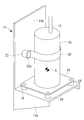
- the compressor 10 has a substantially cylindrical shape having an axis in the vertical direction.
- a compression mechanism such as a scroll compression mechanism and an electric motor for driving the compression mechanism are accommodated.
- the compression mechanism is provided at the upper side, and the electric motor is provided at the lower side. Therefore, the center of gravity G of the compressor 10 is located slightly lower than the intermediate height position of the compressor 10. Electric power is supplied from the outside to the electric motor, and the rotation speed of the compression mechanism is made variable by the power conversion device.
- a discharge pipe 12 for discharging the refrigerant after compression is connected to an upper portion of the compressor 10. Further, an injection pipe (not shown) for supplying a refrigerant at an intermediate pressure to the compression mechanism is also connected to the upper portion of the compressor 10.
- the discharge pipe 12 and the injection pipe have a pipe diameter smaller than a suction pipe (not shown) which is connected to the compressor 10 and sucks the refrigerant.
- the compressor 10 is fixed to a frame (main body) 14.
- the frame 14 is a strength member that supports the devices provided in the housing 6 and bears structural strength.
- the frame 14 includes a lower wall portion 14 a whose upper surface is a horizontal surface, and a vertical wall portion 14 b connected to the lower wall portion 14 a and erected upward.
- a leg 18 is provided below the compressor 10 via a bottom plate 16.
- the bottom plate 16 has a sheet metal structure fixed to the lower end of the main body of the compressor 10, and legs 18 are fixed to each of the four corners.
- the lower portion of the compressor 10 is fixed to the upper surface of the lower wall portion 14 a of the frame 14 through the respective legs 18.
- the positions at which the legs 18 are fixed to the bottom plate 16 are not limited to the four corners, and may be, for example, one in the center of the lower part or three or five or more in the periphery.
- Each leg 18 includes a lower vibration-proof rubber (lower elastic body) (not shown), and serves as a vibration-proof support member (lower vibration-proof support member) for vibration-proof vibration between the compressor 10 and the frame 14. ing.
- a metal band (band) 20 is wound around the body of the compressor 10.
- the installation position of the metal band 20 is above the center of gravity G of the compressor 10.
- the end portion 20 a of the metal band 20 is fixed to the vertical wall portion 14 b of the frame 14 via the upper vibration-proof rubber (upper elastic body) 22.
- the metal band 20 and the upper vibration isolation rubber 22 constitute an upper vibration isolation support member that supports the upper portion of the compressor 10.
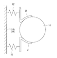
- FIG. 3 shows a vibration model of the support structure by the upper anti-vibration support member.
- an upper anti-vibration rubber 22 which is an elastic body is interposed with respect to the vertical wall portion 14 b of the frame 14 so as to be supported in a flexible structure.
- the spring constant of the upper anti-vibration rubber 22 is larger than that of the anti-vibration rubber provided on the leg portion 18.
- a synthetic spring constant of these anti-vibration rubbers is used. Specifically, the spring constant is adjusted by making the type of the rubber of the upper vibration-proof rubber 22 different from the material and shape of the vibration-proof rubber provided on the leg portion 18.
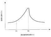
- the spring constant of the upper anti-vibration rubber 22 is set to f0 (Hz) such that the vibration transmission ratio Tr is 1 or less.
- the spring constant is set such that the natural frequency f0 is twice or more the predetermined value f1.
- the predetermined value f1 is a representative frequency representing the traveling time of the refrigerated vehicle 1, and a value defined by a standard such as Japanese Industrial Standard (JIS) is used, for example, 20 Hz.
- JIS Japanese Industrial Standard
- the spring constant (synthetic spring constant) of the vibration-proof rubber (lower vibration-proof rubber) provided in the leg portion 18 may also be larger than the predetermined value f1.
- the lower side of the center of gravity G of the compressor 10 is supported against the lower wall portion 14a of the frame 14 via the leg portion 18, and the upper side of the center of gravity G of the compressor 10 is the frame 14 with the metal band 20 and the upper vibration isolation rubber 22.
- both ends of the center of gravity G of the compressor 10 are supported.
- it is possible to suppress the vibration displacement of the compressor 10 in various vibration directions such as the above-described vibration during traveling of the vehicle and driving vibration of the compressor itself.
- the vibration displacement of the upper portion of the compressor 10 is made relative to the lower portion of the compressor 10 by making the spring constant of the upper vibration-proof rubber 22 larger than the spring constant of the lower vibration-proof rubber provided on the leg portion 18 It can be made smaller. Thereby, even if vibration or the like during traveling of the refrigerator car 1 is input as external vibration, vibration displacement of the upper portion of the compressor 10 can be suppressed, and desired fixed strength of the compressor 10 can be obtained.
- the vibration displacement of the upper portion of the compressor 10 is suppressed by the upper vibration-proof rubber 22 whose spring constant is made larger than that of the lower vibration-proof rubber, so damage to the discharge piping 12 and injection piping can be suppressed.
- the discharge piping, the gas injection piping, and the like are effective because the pipe diameter is smaller than the suction piping and the like.
- the spring constant of the upper anti-vibration rubber 22 is set so that the natural frequency becomes larger than the predetermined value f1 which is a representative frequency representing the traveling time of the refrigerating car 1, the traveling time of the refrigerating car 1 Vibration transmission can prevent the upper part of the compressor 10 from being greatly excited. Further, if the spring constant (synthetic spring constant) of the vibration-proof rubber (lower vibration-proof rubber) provided in the leg portion 18 is also made larger than the predetermined value f1, the vibration of the compressor 10 can be further reduced. .
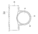
- the upper fixed support structure can be modified as shown in FIG.
- a band-shaped upper vibration isolation rubber 24 may be disposed on the inner peripheral side of the metal band 20.
- the upper vibration damping rubber 24 is wound around the entire circumference of the body of the compressor 10.
- the upper portion of the compressor 10 is supported by interposing the band-shaped upper vibration isolation rubber 24 between the compressor 10 and the metal band 20.
- the end 20 a of the metal band 20 is fixed to the upper fixing bracket 26 fixed to the vertical wall 14 b of the frame 14.
- the upper portion of the compressor 10 is fixed using the metal band 20, and the lower portion of the compressor 10 is fixed using the leg portion 18.
- the present invention is not limited to these fixing methods.
- the structure is not limited, as long as it can be fixed using an elastic body having a predetermined spring constant.
- the bracket 21 is fixed to the side wall of the compressor 10 by welding, casting or the like, and the upper anti-vibration rubber 22 is provided between the bracket 21 and the vertical wall portion 14 b of the frame 14. As well.
- Refrigerated car 1 Refrigerated car 2 Vehicle 3 container (container for transportation) 4 cab 5 transport refrigerator 6 housing 10 compressor 12 discharge piping 14 frame (main body) 14a lower wall portion 14b vertical wall portion 16 bottom plate 18 leg portion (lower anti-vibration support member) 20 Metal band (band, upper anti-vibration support member) 20a End 21 Brackets 22, 24 Upper vibration-proof rubber (upper elastic body) 26 Upper fixed bracket G Center of gravity
Landscapes
- Engineering & Computer Science (AREA)
- Mechanical Engineering (AREA)
- General Engineering & Computer Science (AREA)
- Compressor (AREA)
- Vibration Prevention Devices (AREA)
Abstract
La présente invention concerne une machine de transport frigorifique comprenant un compresseur qui est porté de sorte que les vibrations du compresseur peuvent être régulées et de sorte que le compresseur présente une force d'ancrage agissant contre les vibrations engendrées par le déplacement. La présente invention est équipée : d'un compresseur (10) qui comprime un fluide frigorigène destiné à refroidir un conteneur de transport disposé dans un véhicule ; de parties pieds (18) qui portent le compresseur (10) au-dessous du centre de gravité G sur une partie paroi inférieure (14a) d'un cadre (14), et qui comportent un caoutchouc anti-vibration de partie inférieure ; et d'une bande métallique (20) qui porte le compresseur (10) au-dessus du centre de gravité G contre une partie paroi verticale (14b) du cadre (14) par l'intermédiaire d'un caoutchouc anti-vibration de partie supérieure (22). La constante d'élasticité du caoutchouc anti-vibration de partie supérieure (22) est supérieure à la constante d'élasticité du caoutchouc anti-vibration de partie inférieure des parties pieds (18).
Priority Applications (1)
| Application Number | Priority Date | Filing Date | Title |
|---|---|---|---|
| EP18859687.8A EP3686429B1 (fr) | 2017-09-22 | 2018-09-21 | Machine de transport frigorifique |
Applications Claiming Priority (2)
| Application Number | Priority Date | Filing Date | Title |
|---|---|---|---|
| JP2017-182632 | 2017-09-22 | ||
| JP2017182632A JP6971739B2 (ja) | 2017-09-22 | 2017-09-22 | 輸送用冷凍機 |
Publications (1)
| Publication Number | Publication Date |
|---|---|
| WO2019059373A1 true WO2019059373A1 (fr) | 2019-03-28 |
Family
ID=65811398
Family Applications (1)
| Application Number | Title | Priority Date | Filing Date |
|---|---|---|---|
| PCT/JP2018/035181 Ceased WO2019059373A1 (fr) | 2017-09-22 | 2018-09-21 | Machine de transport frigorifique |
Country Status (3)
| Country | Link |
|---|---|
| EP (1) | EP3686429B1 (fr) |
| JP (1) | JP6971739B2 (fr) |
| WO (1) | WO2019059373A1 (fr) |
Citations (4)
| Publication number | Priority date | Publication date | Assignee | Title |
|---|---|---|---|---|
| JPS57164342U (fr) * | 1981-04-10 | 1982-10-16 | ||
| JPS63191277U (fr) | 1987-05-29 | 1988-12-09 | ||
| JPH0796736A (ja) * | 1993-09-28 | 1995-04-11 | Matsushita Electric Ind Co Ltd | 自動車用圧縮機の防音箱 |
| JP2017066943A (ja) * | 2015-09-29 | 2017-04-06 | 株式会社豊田自動織機 | 圧縮機 |
Family Cites Families (4)
| Publication number | Priority date | Publication date | Assignee | Title |
|---|---|---|---|---|
| JPH04184025A (ja) * | 1990-11-15 | 1992-07-01 | Matsushita Electric Ind Co Ltd | 空気調和機 |
| JP2000234586A (ja) * | 1998-12-17 | 2000-08-29 | Denso Corp | 電動圧縮機の取付構造 |
| JP2015090130A (ja) * | 2013-11-07 | 2015-05-11 | サンデン株式会社 | 電動圧縮機の取付構造 |
| JP2016173042A (ja) * | 2015-03-16 | 2016-09-29 | 株式会社東芝 | 冷媒圧縮装置および冷凍サイクル装置 |
-
2017
- 2017-09-22 JP JP2017182632A patent/JP6971739B2/ja active Active
-
2018
- 2018-09-21 EP EP18859687.8A patent/EP3686429B1/fr active Active
- 2018-09-21 WO PCT/JP2018/035181 patent/WO2019059373A1/fr not_active Ceased
Patent Citations (4)
| Publication number | Priority date | Publication date | Assignee | Title |
|---|---|---|---|---|
| JPS57164342U (fr) * | 1981-04-10 | 1982-10-16 | ||
| JPS63191277U (fr) | 1987-05-29 | 1988-12-09 | ||
| JPH0796736A (ja) * | 1993-09-28 | 1995-04-11 | Matsushita Electric Ind Co Ltd | 自動車用圧縮機の防音箱 |
| JP2017066943A (ja) * | 2015-09-29 | 2017-04-06 | 株式会社豊田自動織機 | 圧縮機 |
Non-Patent Citations (1)
| Title |
|---|
| See also references of EP3686429A4 |
Also Published As
| Publication number | Publication date |
|---|---|
| EP3686429A1 (fr) | 2020-07-29 |
| JP2019056355A (ja) | 2019-04-11 |
| EP3686429B1 (fr) | 2023-04-19 |
| EP3686429A4 (fr) | 2021-04-21 |
| JP6971739B2 (ja) | 2021-11-24 |
Similar Documents
| Publication | Publication Date | Title |
|---|---|---|
| JP3512730B2 (ja) | 回転圧縮機組立体 | |
| US7819638B2 (en) | Compressor mounting system | |
| JP2013148236A (ja) | 空気調和機の室外機、その他の防振装置付きの圧縮機を搭載した機器 | |
| JP6094497B2 (ja) | 電動圧縮機、及び電動圧縮機の製造方法 | |
| CN206637752U (zh) | 空调机的室外机 | |
| WO2019059373A1 (fr) | Machine de transport frigorifique | |
| US3494678A (en) | Vibration-damping bearing | |
| KR100437023B1 (ko) | 공기조화기의 실외기용 지지구조 | |
| JP3863724B2 (ja) | 機械装置の据付機構 | |
| JP2012193934A (ja) | 浴室換気空調装置 | |
| JP2016109399A (ja) | 冷凍装置の熱源ユニット | |
| JP2010209898A (ja) | 空気調和機の室外機 | |
| KR101609551B1 (ko) | 2단 베이스를 사용하는 공기압축기 | |
| JP2000111202A (ja) | 空気調和機 | |
| KR100403656B1 (ko) | 에어컨 실외기의 압축기 지지구조 | |
| JP4064520B2 (ja) | 防振機構を有する冷凍装置 | |
| JP2011038599A (ja) | 冷蔵庫 | |
| JP2001133079A (ja) | 冷凍装置 | |
| US12247633B2 (en) | Vibration isolator and outdoor unit for air-conditioning apparatus | |
| JP2014066488A (ja) | 空気調和装置 | |
| JP6272110B2 (ja) | 車両用空気調和装置 | |
| JP2020122437A (ja) | 圧縮機及びこれを有する機器及び冷蔵庫 | |
| JP5588728B2 (ja) | 車載用冷凍装置のフレーム構造 | |
| JPH06323695A (ja) | 冷凍装置 | |
| JP2003136948A (ja) | 縦置型電動圧縮機用取付装置 |
Legal Events
| Date | Code | Title | Description |
|---|---|---|---|
| 121 | Ep: the epo has been informed by wipo that ep was designated in this application |
Ref document number: 18859687 Country of ref document: EP Kind code of ref document: A1 |
|
| NENP | Non-entry into the national phase |
Ref country code: DE |
|
| ENP | Entry into the national phase |
Ref document number: 2018859687 Country of ref document: EP Effective date: 20200422 |