WO2019064355A1 - Fermeture à glissière - Google Patents
Fermeture à glissière Download PDFInfo
- Publication number
- WO2019064355A1 WO2019064355A1 PCT/JP2017/034815 JP2017034815W WO2019064355A1 WO 2019064355 A1 WO2019064355 A1 WO 2019064355A1 JP 2017034815 W JP2017034815 W JP 2017034815W WO 2019064355 A1 WO2019064355 A1 WO 2019064355A1
- Authority
- WO
- WIPO (PCT)
- Prior art keywords
- fastener
- slider
- base
- tape
- fastener element
- Prior art date
- Legal status (The legal status is an assumption and is not a legal conclusion. Google has not performed a legal analysis and makes no representation as to the accuracy of the status listed.)
- Ceased
Links
Images










Classifications
-
- A—HUMAN NECESSITIES
- A44—HABERDASHERY; JEWELLERY
- A44B—BUTTONS, PINS, BUCKLES, SLIDE FASTENERS, OR THE LIKE
- A44B19/00—Slide fasteners
- A44B19/24—Details
- A44B19/38—Means at the end of stringer by which the slider can be freed from one stringer, e.g. stringers can be completely separated from each other
Definitions
- the present disclosure relates to a slide fastener.
- Patent document 1 provides the female engaging part 34 in the locking piece 11, and provides the male engaging part 20 in the coupling piece 10, as described in Claim 1 etc. of the same document. Disclosed is a disengaging insert which can be disengaged in a direction perpendicular to the surface and which can be pivoted upon their engagement.
- Patent Document 2 discloses, similarly to Patent Document 1, a disengaging insertion tool in which the connection of the female member 7 and the male member 8 and the subsequent rotation of the female member 7 and / or the male member 8 are performed.
- Patent Document 3 also discloses, similarly to Patent Document 1, a disengaging insertion tool in which the coupling 10 and the locking tool 20 are coupled and the coupling tool 10 and / or the locking tool 20 is subsequently rotated.
- U.S. Pat. No. 6,097,099 provides a double helix on each side of the terminations 420, 422 and pushes the terminations 420, 422 together to facilitate rotation of the terminations 420, 422 in the proper direction to engage. Is suggested (upper left column on page 10).
- a slide fastener includes: a first fastener tape; and a first fastener stringer including a first fastener element provided at a side edge extending along the longitudinal direction of the first fastener tape;
- a slider for opening and closing the first and second fastener stringers includes at least an upper wing portion, a lower wing portion, and a connecting post connecting the upper wing portion and the lower wing portion, and sandwiching the connecting post Are provided with first and second front ports, one rear port is provided on the opposite side of the first and second front ports, and the first fastener tape is provided between the first front port and the rear port.
- a slider extending a first slit that permits movement, and a second slit extending allowing movement of the second fastener tape between the second front opening and the rear opening;
- a first stop attached to a first tape area existing between an end of the first fastener tape and the first fastener element, a first base, a first base, and the first fastener element
- a first stop member having a first insertion portion positioned between the two and inserted into the slider via the rear end of the slider
- a second stop member attached to a second tape area existing between the end of the second fastener tape and the second fastener element, comprising a second base, the second base and the second fastener element And a second stop member including a second insertion portion inserted into the slider through the second slit of the slider.
- the second insertion portion is moved toward the second slit of the slider through rotation of at least one of the first and second bases.
- the second insertion portion has an insertion end portion extending between the second base and the second fastener element so as to have a shape corresponding to the contour of the upper wing portion or the lower wing portion.
- the upper wing and / or the lower wing have a corner located on the aft side, and the insertion end is for avoiding interference with the corner Have a notch.
- the insertion end is An extending portion extending along a longitudinal direction of the second fastener tape; A first inclined portion which is provided on the second base side with respect to the extension portion and which inclines inward of the second fastener tape as it is separated from the extension portion; A second inclined portion is provided on the second base side with respect to the first inclined portion, and is inclined toward the outer side of the second fastener tape in accordance with separation from the first inclined portion.
- the insertion end is configured in a tapered shape with an outwardly sloping upper surface and / or an upwardly sloping lower surface of the second fastener tape.
- the first insertion portion has an upper plate portion and a lower plate portion that at least partially define an insertion groove into which the second insertion portion is inserted; A fitting portion that fits into the notch portion of the insertion end portion is provided in the insertion groove.
- the first insertion portion has an upper plate portion and a lower plate portion that at least partially define an insertion groove into which the second insertion portion is inserted;
- the upper plate portion of the first insertion portion has an upper plate inclined portion obliquely inclined upward, and the lower plate portion has a lower plate inclined portion inclined obliquely downward, and the upper plate inclined portion and the above The inlet of the insertion groove is located between the lower plate inclined portions.
- the first base of the first stop member is provided with an axial projection and the second base of the second stop member is provided with a receptacle for receiving the axial projection.
- the outer circumferential portion of the axial projection is provided with at least one inclined surface which is inclined in an arc around the center line of the axial projection;
- the receiving portion is provided with at least one sliding portion capable of sliding on the inclined surface.
- the sliding portion includes a contact edge in contact with the inclined surface, and a projecting piece that protrudes on the opposite side of the contact edge in the circumferential direction with respect to the receiving portion that receives the axial projection.
- the axial protrusion is provided with a recess into which the protrusion is inserted.
- the first and second bases are stacked through rotation of at least one of the first and second bases, In response to the rotation, the second insertion portion moves toward the second slit of the slider, and the distance between the first and second bases decreases.
- the second insertion portion has a shape substantially matching the left or right side surface extending between the front side and the rear side of the lower wing or upper wing of the slider.
- the first stop member comprises a fin provided adjacent to the first fastener element.
- the second retaining member further comprises a third fastener element provided adjacent to the second fastener element, and the groove into which the fin portion is inserted in the third fastener element Is provided.
- the first fastener element comprises a row of the first fastener element and the second fastener element comprises a row of the second fastener element
- the second stop member further comprises a third fastener element coupled to the second insert at a position adjacent to an end of the row of the second fastener elements;
- the third fastener element has a base coupled to the second fastener tape and a head coupled to the base via a neck portion, The width of the head of the third fastener element along the longitudinal direction of the second fastener tape is 1.4 or more times the pitch interval of the second fastener element in the row of the second fastener element.
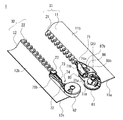
- FIG. 1 is a schematic perspective view of an end portion of a slide fastener according to an aspect of the present disclosure, wherein the first and second fastener stringers are not closed.
- FIG. 2 is a schematic perspective view of an end portion of a slide fastener according to one aspect of the present disclosure, showing the opposite side of the slide fastener of FIG. 1;
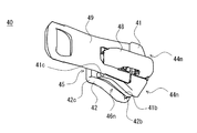
- FIG. 10 is a schematic perspective view of a slider incorporated into a slide fastener according to an aspect of the present disclosure, wherein advancing the slider closes the first and second fastener stringers, and reversing the slider opens the first and second fastener stringers.
- FIG. 1 is a schematic side view of a slider incorporated into a slide fastener according to an aspect of the present disclosure.
- FIG. 5 is a schematic top view of a first stop member included in a slide fastener according to an aspect of the present disclosure. It is a schematic bottom view of the 1st stop member contained in the slide fastener concerning one mode of this indication. It is a schematic right view of the 1st stop member contained in the slide fastener concerning one mode of this indication.
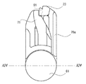
- FIG. 5 is a schematic rear view of a first stop member included in a slide fastener according to an aspect of the present disclosure.
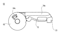
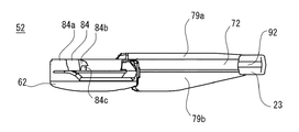
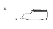
- FIG. 7 is a schematic top view of a second stop member included in the slide fastener according to an aspect of the present disclosure. It is a schematic bottom view of the 2nd stop member contained in the slide fastener concerning one mode of this indication. It is a schematic right view of the 2nd stop member contained in the slide fastener concerning one mode of this indication. Illustration of a fastener tape is omitted.
- FIG. 5 is a schematic rear view of a first stop member included in a slide fastener according to an aspect of the present disclosure.
- a slide fastener according to an aspect of the present disclosure in a process in which the first and second bases are laminated and united through rotation of at least one of a first base of a first stopper and a second base of a second stopper. It is the schematic for demonstrating moving the 2nd insertion part of a 2nd stop member toward a 2nd slit, and the state before a 2nd insertion part approachs into a slider via the 2nd slit of a slider is shown. Show.
- a slide fastener in a process in which the first and second bases are laminated and united through rotation of at least one of a first base of a first stopper and a second base of a second stopper. It is the schematic for demonstrating that the 2nd insertion part of a 2nd stop member moves toward a 2nd slit, and the state after the 2nd insertion part approached into a slider via the 2nd slit of a slider is shown. Show. It is the schematic which shows the slide fastener of FIG. 17 from an other side. It is the schematic which shows the slide fastener of FIG. 18 from an other side.
- FIG. 21 is an enlarged schematic view of a range specified by a circle indicated by a broken line in FIG. 20.
- FIG. 24 is a schematic cross-sectional schematic view taken along the dashed-two dotted line X24-X24 in FIG. 23.
- FIG. 16 is a reference view showing that the insertion end of the second insertion portion extends so as to have a shape according to the contour of the upper wing or lower wing of the slider.
- FIGS. 1 to 28 Each feature included in one or more example embodiments and example embodiments disclosed is not individually independent. Those skilled in the art can combine the exemplary embodiments and / or the respective features without requiring an over description. Those skilled in the art can also understand the synergistic effects of this combination. Duplicate descriptions between example embodiments will be omitted in principle.
- the reference drawings are mainly for the description of the invention and may be simplified for the convenience of drawing.
- a plurality of features described with respect to one slide fastener is understood as a combination of features and as a separate feature independent of other features.
- the individual features are understood not to be limited to one disclosed slide fastener, but also to other slide fasteners not disclosed.
- An individual feature is also understood as a combination with one or more other features. The listing of all combinations of features is redundant for the person skilled in the art and is omitted. In the present specification, individual features can be explicitly distinguished from other descriptions by the expressions “some embodiments” and “some cases”.
- the front-rear direction coincides with the moving direction of the slider. Forward corresponds to the advancing direction of the slider for closing the first and second fastener stringers. Rear corresponds to the reverse direction of the slider for opening the first and second fastener stringers.
- the up-down direction is orthogonal to the front-rear direction and orthogonal to the tape surface of the fastener tape.
- the up-down direction also corresponds to the extending direction of the connecting post that connects the upper and lower wings of the slider.
- the left-right direction is orthogonal to the front-rear direction and the up-down direction. Directions can be defined in another way based on the following description.
- FIG. 1 is a schematic perspective view of an end portion of a slide fastener 1 according to an aspect of the present disclosure, in which the first and second fastener stringers 31, 32 are not closed.
- FIG. 2 is a schematic perspective view of an end portion of the slide fastener 1 according to an aspect of the present disclosure, showing the opposite side of the slide fastener of FIG.
- FIG. 3 is a schematic perspective view of the slider 40 incorporated in the slide fastener 1 according to an aspect of the present disclosure, wherein the advancing of the slider 40 closes the first and second fastener stringers 31 and 32, The first and second fastener stringers 31, 32 are opened by reverse.
- FIG. 4 is a schematic side view of the slider 40 incorporated in the slide fastener 1 according to an aspect of the present disclosure.
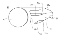
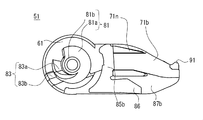
- FIG. 5 is a schematic enlarged perspective view of the first stop member 51 provided at one end portion of the first fastener stringer 31 included in the slide fastener 1 according to an aspect of the present disclosure.
- FIG. 6 is a schematic enlarged perspective view of the second stop member 52 provided at one end portion of the second fastener stringer 32 included in the slide fastener 1 according to an aspect of the present disclosure.
- the first fastener element 21 of the first fastener stringer 31 is passed through the slider 40 (not shown) in FIGS. 1 and 2. This point is well understood from the references in FIG. 17 and FIG.
- the slide fastener 1 has a first fastener stringer 31 and a second fastener stringer 32 as a pair of left and right fastener stringers.
- the slide fastener 1 further has a slider 40 for opening and closing the first and second fastener stringers 31, 32.
- the first fastener stringer 31 has a first fastener tape 11 and a first fastener element 21 provided at a side edge extending along the longitudinal direction of the first fastener tape 11.
- the second fastener stringer 32 has a second fastener tape 12 and a second fastener element 22 provided at a side edge extending along the longitudinal direction of the second fastener tape 12.
- the side edge of the first fastener tape 11 provided with the first fastener element 21 and the side edge of the second fastener tape 12 provided with the second fastener element 22 are arranged opposite to each other, These may be referred to as opposing side edges.
- Each fastener tape has a shape whose length is greater than its width.
- the longitudinal direction of the fastener tape coincides with the direction in which the fastener tape extends so as to have a length, and finally coincides with the direction indicated by the arrow A1 in FIG.
- the longitudinal direction of the fastener tape may simply be referred to as the tape longitudinal direction.
- the width direction of the fastener tape coincides with the direction in which the fastener tape extends so as to have a width, and finally coincides with the direction indicated by the arrow A2 in FIG.
- the width direction of the fastener tape may be simply referred to as the tape width direction.
- Each fastener tape has a pair of tape surfaces defining a thickness.
- the first fastener tape 11 has an upper surface 11a and a lower surface 11b opposite to the upper surface 11a, and the thickness of the first fastener tape 11 is defined by these tape surfaces.
- the second fastener tape 12 also has an upper surface 12a and a lower surface 12b opposite to the upper surface 12a, and the thickness of the second fastener tape 12 is defined by these tape surfaces.
- the surface that defines the thickness of the fastener tape is called a tape surface.
- the first and second fastener elements 21 and 22 are element rows in which resin elements are arranged along the tape longitudinal direction.
- Other types of fastener elements such as metal elements and coiled elements may also be employed.
- Each resin element has a base coupled to the opposite side edge of the fastener tape and a head coupled to the base via a neck.
- the slider 40 incorporated in the slide fastener 1 has an upper wing portion 41, a lower wing portion 42, and a connecting post 43 connecting the upper wing portion 41 and the lower wing portion 42.
- First and second front ports 44m and 44n are provided to sandwich the connection column 43, and one rear port 45 is provided on the opposite side of the first and second front ports 44m and 44n in the front-rear direction.
- a first slit 46m extending between the opening 44m and the rear opening 45 allowing movement of the first fastener tape 11 and a second slit allowing movement of the second fastener tape 12 between the second front opening 44n and the rear opening 45
- the slits 46 n extend.
- the slider 40 has an element passage branched between the upper wing portion 41 and the lower wing portion 42 in a Y-shape by the connecting post 43.
- the first fastener element 21 enters the slider 40 or goes out of the slider 40 via the first front opening 44m.
- the second fastener element 22 enters the slider 40 or goes out of the slider 40 through the second front opening 44 n.
- the meshed first and second fastener elements 21 and 22 enter the slider 40 or go out of the slider 40 through the rear opening 45.
- the upper wing portion 41 of the slider 40 includes an upper wing plate 41a and a pair of upper flange portions 41b which project downward at left and right side edges of the upper wing plate 41a.
- the lower wing portion 42 includes a lower wing plate 42 a and a pair of lower flange portions 42 b projecting upward at left and right side edges of the lower wing plate 42 a. In some cases, one of the upper flange portion 41b and the lower flange portion 42b is omitted.
- the upper blade 41a and the lower blade 42a may be disposed in a plane perpendicular to the vertical direction in which the connecting post 43 extends.
- the slider 40 has a pull attachment bracket 48 and a pull 49 attached to the upper blade 41 a via the pull attachment attachment 48.
- the slider 40 has a locking claw member 47 operated by a pull 49.
- the slide fastener 1 is applied to the first tape area existing between the end 11 e of the first fastener tape 11 and the first fastener element 21. It has a first stop 51 attached and a second stop 52 attached to a second tape area existing between the end 12 e of the second fastener tape 12 and the second fastener element 22.
- the first stop member 51 slightly protrudes rearward of the end 11 e of the first fastener tape 11.
- the second stop member 52 slightly protrudes rearward beyond the end 12 e of the second fastener tape 12.
- the first stop member 51 projects rearward of the end 11 e of the first fastener tape 11 to a degree larger or smaller than the illustrated example. In some cases, the first stop member 51 does not project rearward of the end 11 e of the first fastener tape 11, and the entire first stop member 51 is located forward of the end 11 e of the first fastener tape 11. . Alternatively or additionally, in some cases, the second stop member 52 does not project rearward beyond the end 12 e of the second fastener tape 12, and the entire second stop member 52 is the end of the second fastener tape 12. Located forward of 12e. When the retaining member is made of resin, the retaining member adheres to the tape area.
- the first stop member 51 is located between the first base 61 and the first base 61 and the first fastener element 21, and is inserted into the slider 40 through the rear opening 45 of the slider 40.
- the first insertion portion 71 extends from the first base portion 61 toward the first fastener element 21 along the front-rear direction.
- the second stop member 52 is located between the second base 62, the second base 62 and the second fastener element 22, and is inserted into the slider 40 through the second slit 46n of the slider 40. Having 72.
- the second insertion portion 72 extends from the second base 62 toward the second fastener element 22 along the front-rear direction.
- the second stop member 52 optionally has a third fastener element 23.
- the third fastener element 23 is connected to the front end of the second insertion portion 72.
- the third fastener element 23 is disposed adjacent to the second fastener element 22.
- the third fastener element 23 promotes the ease of movement of the slider 40 when the slider 40 advances with the first insertion portion 71 and the second insertion portion 72 inserted in the slider 40, and / or a fastener It is provided to fill the gap between the element and the stop member.
- the first insert 71 is suitably shaped to facilitate the retention of the slider 40 on the first insert 71.
- the first insertion portion 71 When the first insertion portion 71 is inserted into the slider 40, the movement of the slider 40 is restricted by the first insertion portion 71, whereby the positioning of the slider 40 on the first stop member 51 is promoted.
- the first insertion portion 71 may include a first side surface 71i or a first side surface 71i extending straight in the front-rear direction from the first base 61 or an upper stop wall 85a described later. It has a second side surface 71u that gradually inclines to the left as it extends forward.
- the first side surface 71i and the second side surface 71u correspond to the shape of the inner side surface of the upper flange portion 41b of the slider 40.
- the first insertion portion 71 has an upper plate portion 71a and a lower plate portion 71b, and at least a portion of the insertion groove 80 in which the second insertion portion 72 is inserted by the upper plate portion 71a and the lower plate portion 71b. Defined. By allowing the first insertion portion 71 and the second insertion portion 72 to be fitted, separation of the first stop member 51 and the second stop member 52 once combined can be suppressed. As can be understood from the following description, the second insertion portion 72 is moved by moving the slider 40 forward while the second insertion portion 72 enters the slider 40 through the second slit 46 n of the slider 40.
- the vertical movement of the second insertion portion 72 is preferably restricted between the upper plate portion 71a and the lower plate portion 71b.
- the upper plate portion 71a of the first insertion portion 71 has an upper plate inclined portion 71m obliquely inclined upward, and the lower plate portion 71b obliquely downward.
- An inclined lower plate inclined portion 71n is provided, and an inlet of the insertion groove 80 is positioned between the upper plate inclined portion 71m and the lower plate inclined portion 71n.
- the upper plate inclined portion 71m contacts the inner surface of the upper wing portion 41 (or upper wing plate 41a) of the slider 40.
- the lower plate inclined portion 71 n contacts the inner surface of the lower wing portion 42 (or lower wing plate 42 a) of the slider 40.
- the upper surface of the front end of the upper plate inclined portion 71m is a downward inclined surface, and wear due to contact with the slider 40 is avoided or suppressed.
- the distance A between the uppermost point of the upper plate inclined portion 71m of the first insertion portion 71 and the lowermost point of the lower plate inclined portion 71n in the thickness direction and the inner surface of the upper blade 41a of the slider 40 and the inner surface of the lower blade 42a The relationship of the distance B in the thickness direction satisfies A ⁇ B.
- the first stop member 51 may optionally have an upper stop wall 85a coupled to the upper plate portion 71a of the first insertion portion 71 and a lower stop wall 85b coupled to the lower plate portion 71b of the first insertion portion 71. .
- the vertical height of the lower stop wall 85b is larger than the vertical height of the upper stop wall 85a.
- the upper stop wall 85a is the upper wing plate 41a in the vertical direction in which the connecting post 43 extends.
- the lower stop wall 85b has a height not exceeding the lower surface of the lower blade 42a. Thinning of the first stop member 51 is promoted.
- the first stop member 51 may optionally have a guide wall 86 coupled to the lower stop wall 85b.
- the guide wall 86 extends in the front-rear direction, and guides the movement of the slider 40 onto the first insertion portion 71.
- the first stop member 51 is optionally provided between an upper thin plate portion 87 a provided on the left of the upper plate portion 71 a of the first insertion portion 71 and a lower plate portion 71 b of the first insertion portion 71 and the guide wall 86. It may have a lower thin plate portion 87b provided.
- the upper thin plate portion 87a and the lower thin plate portion 87b promote adhesion of the first stopper 51 to the first fastener tape 11.
- the second stop member 52 optionally has upper and lower stop walls 79a, 79b projecting up and down adjacent to the second insertion portion 72.
- the upper stop wall 79 a can contact the upper flange portion 41 b of the slider 40.
- the lower stop wall 79 b can contact the lower flange portion 42 b of the slider 40.
- the second insertion portion 72 moves toward the second slit 46 n of the slider 40 according to the rotation of at least one of the first and second bases 61 and 62.
- the first and second bases 61, 62 may be stacked and / or united through rotation of at least one of the first and second bases 61, 62.
- the second insertion portion 72 moves toward the second slit 46n of the slider 40, and the distance between the first and second bases 61 and 62 decreases.
- the first and second bases 61, 62 sandwiching the first and second bases 61, 62 between the thumb and forefinger, the second insertion portion 72 moves toward the second slit 46n of the slider 40, and the first and second bases The interval 61, 62 is reduced.
- the second insertion portion 72 is pivoted, and the time and effort for inserting the second insertion portion 72 into the slider 40 is reduced. That is, facilitation of the operation of the first and second stoppers 51, 52 required when closing the slide fastener 1 is promoted.
- the second insert 72 is formed between the second base 62 and the second fastener element 22 in the lower wing 42 (or lower wing 42a). It has an insertion end 73 which extends to have a shape according to the contour. Thereby, the interference between the insertion end 73 and the lower wing 42 is avoided or reduced, and the facilitation of the operation that should result in the movement of the second insertion part 72 toward the second slit 46 n of the slider 40 is promoted. This operation is not necessarily limited to the operation described in the next paragraph.
- the second insertion portion 72 when the second insertion portion 72 takes an initial position in contact with the lower surface of the lower wing portion 42 (see FIG. 26A), the first and second bases 61 and 62 are placed between the thumb and forefinger. When pinched, the second insertion portion 72 passes the right side of the lower wing portion 42 (see FIG. 26B), and can then enter the slider 40 successfully through the second slit 46 n (FIG. 26 (FIG. c) see Smoothing of the operation of the first and second stop members 51, 52 required when closing the slide fastener 1 is further promoted.
- the insertion end 73 extends to have a shape according to the contour of the upper wing 41 (or upper wing 41a).
- the second insertion portion 72 may be a left or right side surface (which may be referred to as a lateral side surface) extending between the front side 42p and the rear side 42q of the lower wing 42 (or upper wing 41) of the slider 40. It extends to have a shape substantially conforming to 42r (see FIG. 4).
- the second insertion portion 72 is a left or right side surface (which may be called a lateral side surface) 42r extending between the front side surface 42p and the rear side surface 42q of the lower blade 42a (or the upper blade 41a) of the slider 40. It can extend to have a shape substantially conforming to
- the upper wing portion 41 and / or the lower wing portion 42 have the corners 41c and 42c located on the rear port 45 side, and the insertion end 73 avoids interference with the corners 41c and 42c. And a notch 74 for the purpose. By providing the notches 74, interference with the corners 41c and 42c of the slider 40 can be effectively avoided or reduced.
- the insertion end 73 is provided on the extension 75 extending along the longitudinal direction of the second fastener tape 12 and on the second base 62 side of the extension 75 and is spaced apart from the extension 75
- the first inclined portion 76 which inclines inward of the second fastener tape 12 according to the second fastener tape 12, and is provided closer to the second base 62 than the first inclined portion 76 and according to being separated from the first inclined portion 76 It has a second inclined portion 77 which inclines outward of the second fastener tape 12.
- the inside of the second fastener tape 12 is a direction from the position outside the tape surface of the second fastener tape 12 to the position on the tape surface of the second fastener tape 12. In this case, it is made sharp by the arrow D1.
- the outward direction of the second fastener tape 12 is a direction from the position on the tape surface of the second fastener tape 12 toward the position on the outside of the tape surface of the second fastener tape 12. In this case, it is clearly indicated by the arrow D2.
- the inward of the first fastener tape 11 is clearly shown by the arrow D3.
- the outward direction of the first fastener tape 11 is clearly shown by the arrow D4.
- the extension 75 is at the front portion of the upper or lower flange portions 41b, 42b. It extends along the left or right side (which may be called the lateral side) and optionally extends substantially parallel.
- the first inclined portion 76 is a left portion of the rear portion of the upper or lower flange portions 41b, 42b.
- the right side which may be referred to as the lateral side
- the second inclined portion 77 extends along the rear surface of the upper blade 41a or the lower blade 42a. Extend, optionally extending substantially parallel.
- the first ramp 76 and the second ramp 77 are provided to intersect at an angle within the range of 85 ° to 95 °.
- the insertion end 73 is configured to taper outwardly of the second fastener tape 12.
- the insertion end 73 may be configured in a tapered shape by the downward sloping upper surface and / or the upward sloping lower surface.
- the second insertion portion 72 has the insertion end 73 extending so as to have a shape according to the contour of the lower wing 42 (or the lower wing 42 a), and the insertion end 73
- a notch 74 is provided to avoid interference with the corners 41c and 42c of the upper wing 41 and / or the lower wing 42 of the slider 40, whereby the second wing 72 and the upper wing of the slider 40 are provided.
- the insertion end portion 73 is configured as described above, even if the second insertion portion 72 interferes with the upper wing portion 41 and / or the lower wing portion 42 due to the taper or the tapered shape, the second insertion portion 72 is an upper wing It is possible to move toward the second slit 46 n of the slider 40 by properly avoiding the portion 41 and / or the lower wing portion 42.
- the first fastener tape 11, the first fastener element 21 and the first fastener stringer 31 may be alternatively referred to as a left fastener tape, a left fastener element and a left fastener stringer, respectively.
- the second fastener tape 12, the second fastener element 22, and the second fastener stringer 32 may alternatively be referred to as a right fastener tape, a right fastener element, and a right fastener stringer, respectively.
- the first retaining member 51 and the second retaining member 52 may alternatively be referred to as a left retaining member and a right retaining member, respectively.
- the first insert 71 and the second insert 72 may alternatively be referred to as a left insert and a right insert, respectively. If appropriate, the first may be replaced by "left" and the second by "right".
- the first and second fastener tapes 11 and 12 may be a flexible woven or knitted fabric.
- the slider 40 may be made of metal or resin.
- the first and second stoppers 51, 52 may be made of resin, but this is not necessarily the case and may be made of other materials such as metal.
- the fastener element is attached to the fastener tape by injection molding. Subsequently, the retaining member is attached to the fastener tape by injection molding. Subsequently, the fastener elements of one fastener stringer are passed through the slider. Thus, the slide fastener 1 can be manufactured.
- the first base 61 of the first stop 51 is provided with a stem 81 and the second base 62 of the second stop 52 is provided with a receptacle 82 for receiving the stem 81.
- the axial projection 81 on the first base 61 thinning of the second base 62 can be promoted, and the ease of use or the appearance of the slide fastener 1 can be improved.
- the shaft-like protrusion 81 is provided on the first base 61 using a space for the upper and lower thickness of the slider 40, and the presence of the shaft-like protrusion 81 is provided on the second base 62 Inconspicuous.
- the axial projection 81 is received by the receiving portion 82, the initial alignment of the first base 61 and the second base 62 is easily or reliably ensured, and / or the rotation of the second base 62 with respect to the first base 61 and The stability of rotation of the first base 61 relative to the second base 62 is enhanced.
- At least one inclined surface 83 is provided on the outer peripheral portion of the axial projection 81 and inclined in an arc around the center line CX1 of the axial projection 81, and the receiving portion 82 slides on the inclined surface 83 At least one slide 84 is provided which is possible.
- the sliding portion 84 descends the inclined surface 83 (FIG. 5). Arrow D5). In this way, the vertical force is converted into a force that causes the first base 61 and / or the second base 62 to rotate.
- the slide 84 projects in some cases into the interior of the receiver 82 and, more particularly, radially inward with respect to the receiver 82 receiving the axial projection 81.
- Coaxially arranging the first base 61 and the second base 62 is achieved by arranging the first base 61 on the second base 62.
- the axial protrusion 81 of the first base 61 is inserted into the receiving portion 82 of the second base 62, and the center line CX1 of the axial protrusion 81 and the center line CX2 of the receiving portion 82 coincide with each other.
- the coincident center lines CX1 and CX2 are represented as rotation axis AX in FIG.
- first base 61 is disposed on the second base 62 so that the center line CX1 and the center line CX2 do not coincide with each other. Also in such a case, the center line CX1 and the center line CX2 may coincide with each other in the process of sandwiching the first base 61 and the second base 62 between the thumb and the index finger or as a result.
- the inclined surface 83 has two or more inclined surfaces provided at different positions in the radial direction with respect to the axial projection 81. Additionally, these two or more inclined surfaces may be provided radially adjacent to the axial protrusion 81. In addition, these two or more inclined surfaces are provided at different positions also in the circumferential direction with respect to the axial projection 81.
- the inclined surface 83 is the first inclined surface 83 a provided closer to the inner diameter in the radial direction with respect to the axial protrusion 81 and the outer diameter closer in the radial direction with respect to the axial protrusion 81 And a second inclined surface 83b provided on the The first inclined surface 83a and the second inclined surface 83b are provided adjacent to each other in the radial direction.
- the first inclined surface 83a and the second inclined surface 83b are provided at different positions in the circumferential direction.
- the degree of inclination and / or the surface shape of the first inclined surface 83a is different from the degree of inclination and / or the surface shape of the second inclined surface 83b.
- the form in which the 3rd slope is provided is also assumed.
- the inclined surface 83 slopes downward so as to be separated from the first fastener tape 11.
- the thickness decreases in the downward direction on the inclined surface 83.
- the sliding portion 84 is in the circumferential direction (e.g., the circumferential direction of the center line CX2 of the receiving portion 82) with respect to the receiving portion 82 that receives the contact edge 84a contacting the inclined surface 83 and the axial projection 81.
- a protrusion 84b is provided on the opposite side of the contact edge 84a (see FIG. 12), and the axial projection 81 is provided with a recess 81j into which the protrusion 84b is inserted (see FIG. 9).
- the sliding portion 84 finishes moving down the inclined surface 83, the protrusion 84b and the recess 81j fit.
- the axial projection 81 has a projection 81c formed by the recess 81j, and a hole 84c for receiving the projection 81c is provided below the projection 84b (see FIG. 12).
- the holes 84 c penetrate or do not penetrate the second base 62.
- the upper surface of the projection 84b is an inclined surface that inclines downward toward the tip of the projection 84b.
- the axial protrusion 81 includes a frusto-conical portion 81a and a cylindrical tip portion 81b coupled to the frusto-conical portion 81a.
- the receiving portion 82 has a main portion 82a for receiving the truncated cone portion 81a and a bottom hole 82b for receiving the cylindrical tip portion 81b.
- the side surface of the cylindrical tip portion 81b has a smaller angle with respect to the center line CX1 of the axial projection 81 than the side surface of the truncated cone portion 81a.
- the side surface of the cylindrical tip 81b includes a region parallel to the center line CX1 of the axial protrusion 81.
- the cylindrical tip 81b fits into the bottom hole 82b, and movement of the cylindrical tip 81b by the bottom hole 82b, which is orthogonal to the vertical direction Its movement in the plane is constrained. Thereby, unintended separation of the first base 61 and the second base 62 is avoided or suppressed.
- the axial protrusion 81 may be provided at the central portion of the circular first base 61 when viewed along the vertical direction.
- the receiving portion 82 may be provided at the central portion of the circular second base 62 as viewed in the vertical direction.
- the axial projection 81 is provided on the upper surface of the first base 61 and extends along the center line CX1 parallel to the vertical direction.
- the receiver 82 is provided in a manner to penetrate the second base 62 and extends along the vertically parallel center line CX2.
- the first stop member 51 has a fin portion 91 provided adjacent to the first fastener element 21.
- the third fastener element 23 is provided with a groove 92 into which the fin portion 91 is inserted.
- the first base portion 61 is not correctly disposed on the second base portion 62, that is, in the state where the axial projection 81 and the receiving portion 82 are not fitted (in FIG. The portion 81 b is offset from the bottom hole 82 b), and the first insertion portion 71 and the second insertion portion 72 are inserted into the slider 40.
- the fin portion 91 is provided, when the slider 40 is advanced from the incorrect initial state shown in FIG.
- the fin portion 91 of the first insertion portion 71 contacts the connecting post 43, and the left side surface 71k of the first insertion portion 71 Contact the upper flange portion 41b. This prevents the advance of the slider 40. For this reason, the slider 40 is advanced in a state where the axial projection 81 is not properly disposed in the receiving portion 82, and the engagement of the first and second fastener elements 21 and 22 is avoided or suppressed.
- the first fastener element 21 comprises an array of first fastener elements 21 and the second fastener element 22 comprises an array of second fastener elements 22.
- the third fastener element 23 is coupled to the second insert 72 at a position adjacent to the end of the row of second fastener elements 22. As shown in FIG. 17, the third fastener element 23 has a base 23a coupled to the second fastener tape 12, and a head 23c coupled to the base 23a via a neck.
- the width W23 of the head of the third fastener element 23 along the longitudinal direction of the second fastener tape 12 is 1.4 or more times the pitch interval W22 of the second fastener elements 22 in the row of the second fastener elements 22.
- the width W23 of the head is less than twice the pitch interval W22. It is assumed that the first base 61 is not correctly disposed on the second base 62 (see FIG. 28). In FIG. 28, the first fastener element 21 is inserted into the slider 40, and the third fastener element 23 of the second insertion portion 72 is inserted into the slider 40 from the second front opening 44 n of the slider 40. This is an incorrect initial state in which the first insertion portion 71 is not inserted into the slider 40. Even when trying to advance the slider 40 in this incorrect initial state, the third fastener element 23 is coupled to the first fastener element 21 in the slider 40 in order to satisfy the above-mentioned relationship of the head width W23 to the pitch interval W22. In this case, the first and second fastener elements 21 and 22 can be prevented or prevented from being bonded while the first and second stoppers 51 and 52 are not bonded.
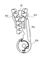
- FIGS. 17 and 18 show the slide fastener 1 according to an aspect of the present disclosure through rotation of at least one of the first base 61 of the first stopper 51 and the second base 62 of the second stopper 52.
- FIG. 17 is a schematic view for illustrating movement of the second insertion portion 72 of the second stopping member 52 toward the second slit 46 n of the slider 40 in the process of stacking and combining the two bases 61 and 62.
- FIG. 17 shows a state before the second insertion portion 72 enters the slider 40 through the second slit 46 n of the slider 40.
- FIG. 18 shows a state after the second insertion portion 72 has entered into the slider 40 through the second slit 46 n of the slider 40.
- FIG. 17 is a schematic view for illustrating movement of the second insertion portion 72 of the second stopping member 52 toward the second slit 46 n of the slider 40 in the process of stacking and combining the two bases 61 and 62.
- FIG. 17 shows a state before the second insertion portion
- FIG. 19 is a schematic view showing the slide fastener 1 of FIG. 17 from the opposite side.
- FIG. 20 is a schematic view showing the slide fastener 1 of FIG. 18 from the opposite side.
- FIG. 21 is an enlarged schematic view of a range specified by a circle indicated by a broken line in FIG.
- FIG. 22 is a slide fastener 1 according to an aspect of the present disclosure, in which the fitting portion 71c of the first insertion portion 71 is fitted to the cutout portion 74 provided in the insertion end portion 73 of the second insertion portion 72. It is a schematic cross-sectional schematic diagram which shows a state.
- FIG. 23 is a schematic top view showing the slide fastener 1 according to an embodiment of the present disclosure in which the first and second stoppers 51 and 52 are coupled.
- FIG. 23 is a schematic top view showing the slide fastener 1 according to an embodiment of the present disclosure in which the first and second stoppers 51 and 52 are coupled.
- first base 61 and the second base 62 are a schematic cross-sectional schematic view taken along the dashed-two dotted line X24-X24 in FIG. It should be noted that in some cases the combination of the first base 61 and the second base 62 means that the separation of both is restricted in at least one arbitrary direction, for example, the vertical direction or the horizontal direction. .
- the slider 40 is first disposed on the first stop member 51.
- the first insertion portion 71 of the first stop member 51 enters the slider 40 through the rear opening 50 of the slider 40.
- the upper wing portion 41 (or upper wing plate 41a) of the slider 40 contacts the upper stop wall 85a coupled to the upper plate portion 71a of the first insertion portion 71, and the lower wing portion 42 (or lower wing) of the slider 40
- the plate 42 a) contacts the lower stop wall 85 b coupled to the lower plate portion 71 b of the first insertion portion 71.
- the first base 61 and the second base 62 are coaxially arranged, and the axial projection 81 of the first base 61 is inserted into the receiving portion 82 of the second base 62.
- the first base 61 and the second base 62 are sandwiched between the thumb and forefinger, the rotation of the first base 61 and / or the second base 62 occurs, and the sliding portion 84 of the second base 62 Go down the inclined surface 83 provided on the outer peripheral portion.
- the second insertion portion 72 of the second stopping member 52 moves toward the second slit 46 n of the slider 40 and enters the slider 40 through the second slit 46 n.
- the vertical distance between the first base 61 and the second base 62 is narrowed, and finally, the first base 61 is stacked on the second base 62, and both are combined.
- the projection 84 b of the sliding portion 84 is inserted into the recess 81 j of the axial projection 81.
- the second insertion portion 72 is inserted into the insertion groove 80 between the upper plate portion 71 a and the lower plate portion 71 b of the first insertion portion 71 as the slider 40 advances.
- the fin portion 91 of the first retaining member 51 is inserted into the groove 92 of the third fastener element 23 of the second retaining member 52.
- the fitting portion 71 c provided in the insertion groove 80 of the first stopper member 51 is fitted in the notch portion 74 of the insertion end portion 73 of the second insertion portion 72 of the second stopper member 52.
- the fitting portion 71 c may be provided on the bottom surface of the insertion groove 80.
- the fitting portion 71c can be coupled to the upper plate portion 71a and / or the lower plate portion 71b. It is avoided or suppressed that the cylindrical tip portion 81b fits in the bottom hole portion 82b, and the truncated cone portion 81a slides out of the main portion 82a and the first base 61 and the second base 62 are separated.
- first fastener tape 12 second fastener tape 21 first fastener element 22 second fastener element 31 first fastener stringer 32 second fastener stringer 40 slider 71 first insertion portion 72 second insertion portion
Landscapes
- Slide Fasteners (AREA)
- Connection Of Plates (AREA)
- Snaps, Bayonet Connections, Set Pins, And Snap Rings (AREA)
Abstract
Dans la présente invention, un premier élément d'arrêt (51) comprend une première section de base (61) et une première section d'insertion (71) qui est située entre la première section de base (61) et un premier élément de fixation (21) et est insérée dans un curseur (40) par le biais d'une ouverture arrière (45) du curseur (40). Un second élément d'arrêt (52) comprend une seconde section de base (62) et une seconde section d'insertion (72) qui est située entre la seconde section de base (62) et un second élément de fixation (22) et est insérée dans le curseur (40) par le biais d'une seconde fente (46n) du curseur (40). La seconde section d'insertion (72) se déplace vers la seconde fente (46n) du curseur (40) à la suite de la rotation de la première section de base (61) et/ou de la seconde section de base (62). La seconde section d'insertion (72) comprend une section de pointe d'insertion (73) qui s'étend entre la seconde section de base (62) et le second élément de fixation (22) de sorte à avoir une forme correspondant au contour d'une section d'aile supérieure (41) ou d'une section d'aile inférieure (42).
Priority Applications (3)
| Application Number | Priority Date | Filing Date | Title |
|---|---|---|---|
| CN201780095330.5A CN111148446B (zh) | 2017-09-26 | 2017-09-26 | 拉链 |
| PCT/JP2017/034815 WO2019064355A1 (fr) | 2017-09-26 | 2017-09-26 | Fermeture à glissière |
| TW107106401A TWI678984B (zh) | 2017-09-26 | 2018-02-26 | 拉鏈 |
Applications Claiming Priority (1)
| Application Number | Priority Date | Filing Date | Title |
|---|---|---|---|
| PCT/JP2017/034815 WO2019064355A1 (fr) | 2017-09-26 | 2017-09-26 | Fermeture à glissière |
Publications (1)
| Publication Number | Publication Date |
|---|---|
| WO2019064355A1 true WO2019064355A1 (fr) | 2019-04-04 |
Family
ID=65901305
Family Applications (1)
| Application Number | Title | Priority Date | Filing Date |
|---|---|---|---|
| PCT/JP2017/034815 Ceased WO2019064355A1 (fr) | 2017-09-26 | 2017-09-26 | Fermeture à glissière |
Country Status (3)
| Country | Link |
|---|---|
| CN (1) | CN111148446B (fr) |
| TW (1) | TWI678984B (fr) |
| WO (1) | WO2019064355A1 (fr) |
Cited By (1)
| Publication number | Priority date | Publication date | Assignee | Title |
|---|---|---|---|---|
| CN114096175A (zh) * | 2019-09-10 | 2022-02-25 | Ykk株式会社 | 拉链牙链带、其制造方法以及拉链 |
Citations (4)
| Publication number | Priority date | Publication date | Assignee | Title |
|---|---|---|---|---|
| JPS55457U (fr) * | 1978-06-15 | 1980-01-05 | ||
| JP2004248809A (ja) * | 2003-02-19 | 2004-09-09 | Ykk Corp | スライドファスナー用開離嵌挿具 |
| WO2010089846A1 (fr) * | 2009-02-03 | 2010-08-12 | Ykk株式会社 | Fermeture à glissière |
| JP3170902U (ja) * | 2011-07-25 | 2011-10-06 | Ykk株式会社 | スライドファスナー用開離嵌挿具及びスライドファスナー |
Family Cites Families (9)
| Publication number | Priority date | Publication date | Assignee | Title |
|---|---|---|---|---|
| DE2603241C3 (de) * | 1976-01-29 | 1979-08-16 | Optilon W. Erich Heilmann Gmbh, Cham (Schweiz) | Reißverschluß mit teilbarer Endkupplung |
| JP2000232908A (ja) * | 1999-02-15 | 2000-08-29 | Ykk Corp | スライドファスナーの開離嵌挿具 |
| JP3733343B2 (ja) * | 2002-05-20 | 2006-01-11 | Ykk株式会社 | スライドファスナー用開離嵌挿具 |
| JP4628329B2 (ja) * | 2006-08-17 | 2011-02-09 | Ykk株式会社 | 開離嵌挿具付きスライドファスナー |
| WO2009153885A1 (fr) * | 2008-06-20 | 2009-12-23 | Ykk株式会社 | Dispositif d’ouverture pour fermeture à glissière |
| ES2537966T3 (es) * | 2008-10-06 | 2015-06-16 | Ykk Corporation | Cierre de cremallera |
| CN102106630B (zh) * | 2009-12-24 | 2013-04-10 | 福建浔兴拉链科技股份有限公司 | 闭口拉链下止及使用该下止的闭口拉链 |
| JP5414895B2 (ja) * | 2010-06-23 | 2014-02-12 | Ykk株式会社 | スライドファスナー |
| CN206507448U (zh) * | 2016-12-22 | 2017-09-22 | Ykk株式会社 | 拉链 |
-
2017
- 2017-09-26 WO PCT/JP2017/034815 patent/WO2019064355A1/fr not_active Ceased
- 2017-09-26 CN CN201780095330.5A patent/CN111148446B/zh active Active
-
2018
- 2018-02-26 TW TW107106401A patent/TWI678984B/zh active
Patent Citations (4)
| Publication number | Priority date | Publication date | Assignee | Title |
|---|---|---|---|---|
| JPS55457U (fr) * | 1978-06-15 | 1980-01-05 | ||
| JP2004248809A (ja) * | 2003-02-19 | 2004-09-09 | Ykk Corp | スライドファスナー用開離嵌挿具 |
| WO2010089846A1 (fr) * | 2009-02-03 | 2010-08-12 | Ykk株式会社 | Fermeture à glissière |
| JP3170902U (ja) * | 2011-07-25 | 2011-10-06 | Ykk株式会社 | スライドファスナー用開離嵌挿具及びスライドファスナー |
Cited By (2)
| Publication number | Priority date | Publication date | Assignee | Title |
|---|---|---|---|---|
| CN114096175A (zh) * | 2019-09-10 | 2022-02-25 | Ykk株式会社 | 拉链牙链带、其制造方法以及拉链 |
| CN114096175B (zh) * | 2019-09-10 | 2023-10-13 | Ykk株式会社 | 拉链牙链带、其制造方法以及拉链 |
Also Published As
| Publication number | Publication date |
|---|---|
| CN111148446A (zh) | 2020-05-12 |
| TWI678984B (zh) | 2019-12-11 |
| TW201914469A (zh) | 2019-04-16 |
| CN111148446B (zh) | 2022-09-13 |
Similar Documents
| Publication | Publication Date | Title |
|---|---|---|
| EP1889552B1 (fr) | Fermeture à glissière à butée inférieure détachable | |
| CN102892325B (zh) | 拉链 | |
| CN207236287U (zh) | 旋转机构、拉链用的能分离的止动件和拉链 | |
| WO2019064356A1 (fr) | Fermeture à glissière | |
| JP5106680B2 (ja) | 開離嵌挿具付きスライドファスナー | |
| JP5832522B2 (ja) | 開離嵌挿具付きスライドファスナー | |
| JP6891272B2 (ja) | スライドファスナー | |
| US20070258795A1 (en) | Parts attaching structure | |
| EP2604139A1 (fr) | Fermeture à glissière | |
| JPWO2011161784A1 (ja) | スライドファスナー | |
| EP2460430A1 (fr) | Fermeture à glissière | |
| US10188180B2 (en) | Slider for slide fastener | |
| CN111148446B (zh) | 拉链 | |
| JP7356879B2 (ja) | 開具及び逆開スライドファスナー | |
| TWI630882B (zh) | Zipper slider | |
| CN209788677U (zh) | 拉片及拉链用拉头 | |
| WO2019003318A1 (fr) | Outil de maintien pour maintenir un curseur et procédé de maintien | |
| WO2022118376A1 (fr) | Butée supérieure divisée | |
| CN116685233A (zh) | 拉链 | |
| US8894111B2 (en) | Slide fastener closing tool and method | |
| JP6926606B2 (ja) | ステープラ | |
| JP2019070251A (ja) | 引戸用の引手とその施工法 | |
| JP6926607B2 (ja) | ステープラ | |
| CN103269615A (zh) | 拉链用拉头 | |
| WO2019229851A1 (fr) | Curseur côté réception et fermeture à glissière à ouverture inversée |
Legal Events
| Date | Code | Title | Description |
|---|---|---|---|
| 121 | Ep: the epo has been informed by wipo that ep was designated in this application |
Ref document number: 17927539 Country of ref document: EP Kind code of ref document: A1 |
|
| NENP | Non-entry into the national phase |
Ref country code: DE |
|
| 122 | Ep: pct application non-entry in european phase |
Ref document number: 17927539 Country of ref document: EP Kind code of ref document: A1 |
|
| NENP | Non-entry into the national phase |
Ref country code: JP |