WO2019064539A1 - Système de pile à combustible et procédé de commande de système de pile à combustible - Google Patents
Système de pile à combustible et procédé de commande de système de pile à combustible Download PDFInfo
- Publication number
- WO2019064539A1 WO2019064539A1 PCT/JP2017/035636 JP2017035636W WO2019064539A1 WO 2019064539 A1 WO2019064539 A1 WO 2019064539A1 JP 2017035636 W JP2017035636 W JP 2017035636W WO 2019064539 A1 WO2019064539 A1 WO 2019064539A1
- Authority
- WO
- WIPO (PCT)
- Prior art keywords
- fuel
- fuel cell
- temperature
- flow rate
- raw
- Prior art date
- Legal status (The legal status is an assumption and is not a legal conclusion. Google has not performed a legal analysis and makes no representation as to the accuracy of the status listed.)
- Ceased
Links
Images






Classifications
-
- H—ELECTRICITY
- H01—ELECTRIC ELEMENTS
- H01M—PROCESSES OR MEANS, e.g. BATTERIES, FOR THE DIRECT CONVERSION OF CHEMICAL ENERGY INTO ELECTRICAL ENERGY
- H01M8/00—Fuel cells; Manufacture thereof
- H01M8/04—Auxiliary arrangements, e.g. for control of pressure or for circulation of fluids
- H01M8/04007—Auxiliary arrangements, e.g. for control of pressure or for circulation of fluids related to heat exchange
- H01M8/04014—Heat exchange using gaseous fluids; Heat exchange by combustion of reactants
- H01M8/04022—Heating by combustion
-
- H—ELECTRICITY
- H01—ELECTRIC ELEMENTS
- H01M—PROCESSES OR MEANS, e.g. BATTERIES, FOR THE DIRECT CONVERSION OF CHEMICAL ENERGY INTO ELECTRICAL ENERGY
- H01M8/00—Fuel cells; Manufacture thereof
- H01M8/04—Auxiliary arrangements, e.g. for control of pressure or for circulation of fluids
- H01M8/04223—Auxiliary arrangements, e.g. for control of pressure or for circulation of fluids during start-up or shut-down; Depolarisation or activation, e.g. purging; Means for short-circuiting defective fuel cells
- H01M8/04225—Auxiliary arrangements, e.g. for control of pressure or for circulation of fluids during start-up or shut-down; Depolarisation or activation, e.g. purging; Means for short-circuiting defective fuel cells during start-up
-
- H—ELECTRICITY
- H01—ELECTRIC ELEMENTS
- H01M—PROCESSES OR MEANS, e.g. BATTERIES, FOR THE DIRECT CONVERSION OF CHEMICAL ENERGY INTO ELECTRICAL ENERGY
- H01M8/00—Fuel cells; Manufacture thereof
- H01M8/04—Auxiliary arrangements, e.g. for control of pressure or for circulation of fluids
- H01M8/04298—Processes for controlling fuel cells or fuel cell systems
- H01M8/043—Processes for controlling fuel cells or fuel cell systems applied during specific periods
- H01M8/04302—Processes for controlling fuel cells or fuel cell systems applied during specific periods applied during start-up
-
- H—ELECTRICITY
- H01—ELECTRIC ELEMENTS
- H01M—PROCESSES OR MEANS, e.g. BATTERIES, FOR THE DIRECT CONVERSION OF CHEMICAL ENERGY INTO ELECTRICAL ENERGY
- H01M8/00—Fuel cells; Manufacture thereof
- H01M8/04—Auxiliary arrangements, e.g. for control of pressure or for circulation of fluids
- H01M8/04082—Arrangements for control of reactant parameters, e.g. pressure or concentration
- H01M8/04201—Reactant storage and supply, e.g. means for feeding, pipes
-
- H—ELECTRICITY
- H01—ELECTRIC ELEMENTS
- H01M—PROCESSES OR MEANS, e.g. BATTERIES, FOR THE DIRECT CONVERSION OF CHEMICAL ENERGY INTO ELECTRICAL ENERGY
- H01M8/00—Fuel cells; Manufacture thereof
- H01M8/04—Auxiliary arrangements, e.g. for control of pressure or for circulation of fluids
- H01M8/04223—Auxiliary arrangements, e.g. for control of pressure or for circulation of fluids during start-up or shut-down; Depolarisation or activation, e.g. purging; Means for short-circuiting defective fuel cells
- H01M8/04268—Heating of fuel cells during the start-up of the fuel cells
-
- H—ELECTRICITY
- H01—ELECTRIC ELEMENTS
- H01M—PROCESSES OR MEANS, e.g. BATTERIES, FOR THE DIRECT CONVERSION OF CHEMICAL ENERGY INTO ELECTRICAL ENERGY
- H01M8/00—Fuel cells; Manufacture thereof
- H01M8/04—Auxiliary arrangements, e.g. for control of pressure or for circulation of fluids
- H01M8/04298—Processes for controlling fuel cells or fuel cell systems
- H01M8/04313—Processes for controlling fuel cells or fuel cell systems characterised by the detection or assessment of variables; characterised by the detection or assessment of failure or abnormal function
- H01M8/0432—Temperature; Ambient temperature
-
- H—ELECTRICITY
- H01—ELECTRIC ELEMENTS
- H01M—PROCESSES OR MEANS, e.g. BATTERIES, FOR THE DIRECT CONVERSION OF CHEMICAL ENERGY INTO ELECTRICAL ENERGY
- H01M8/00—Fuel cells; Manufacture thereof
- H01M8/04—Auxiliary arrangements, e.g. for control of pressure or for circulation of fluids
- H01M8/04298—Processes for controlling fuel cells or fuel cell systems
- H01M8/04313—Processes for controlling fuel cells or fuel cell systems characterised by the detection or assessment of variables; characterised by the detection or assessment of failure or abnormal function
- H01M8/0432—Temperature; Ambient temperature
- H01M8/04328—Temperature; Ambient temperature of anode reactants at the inlet or inside the fuel cell
-
- H—ELECTRICITY
- H01—ELECTRIC ELEMENTS
- H01M—PROCESSES OR MEANS, e.g. BATTERIES, FOR THE DIRECT CONVERSION OF CHEMICAL ENERGY INTO ELECTRICAL ENERGY
- H01M8/00—Fuel cells; Manufacture thereof
- H01M8/04—Auxiliary arrangements, e.g. for control of pressure or for circulation of fluids
- H01M8/04298—Processes for controlling fuel cells or fuel cell systems
- H01M8/04313—Processes for controlling fuel cells or fuel cell systems characterised by the detection or assessment of variables; characterised by the detection or assessment of failure or abnormal function
- H01M8/0432—Temperature; Ambient temperature
- H01M8/04373—Temperature; Ambient temperature of auxiliary devices, e.g. reformers, compressors, burners
-
- H—ELECTRICITY
- H01—ELECTRIC ELEMENTS
- H01M—PROCESSES OR MEANS, e.g. BATTERIES, FOR THE DIRECT CONVERSION OF CHEMICAL ENERGY INTO ELECTRICAL ENERGY
- H01M8/00—Fuel cells; Manufacture thereof
- H01M8/04—Auxiliary arrangements, e.g. for control of pressure or for circulation of fluids
- H01M8/04298—Processes for controlling fuel cells or fuel cell systems
- H01M8/04694—Processes for controlling fuel cells or fuel cell systems characterised by variables to be controlled
- H01M8/04701—Temperature
- H01M8/04708—Temperature of fuel cell reactants
-
- H—ELECTRICITY
- H01—ELECTRIC ELEMENTS
- H01M—PROCESSES OR MEANS, e.g. BATTERIES, FOR THE DIRECT CONVERSION OF CHEMICAL ENERGY INTO ELECTRICAL ENERGY
- H01M8/00—Fuel cells; Manufacture thereof
- H01M8/04—Auxiliary arrangements, e.g. for control of pressure or for circulation of fluids
- H01M8/04298—Processes for controlling fuel cells or fuel cell systems
- H01M8/04694—Processes for controlling fuel cells or fuel cell systems characterised by variables to be controlled
- H01M8/04746—Pressure; Flow
- H01M8/04753—Pressure; Flow of fuel cell reactants
-
- H—ELECTRICITY
- H01—ELECTRIC ELEMENTS
- H01M—PROCESSES OR MEANS, e.g. BATTERIES, FOR THE DIRECT CONVERSION OF CHEMICAL ENERGY INTO ELECTRICAL ENERGY
- H01M8/00—Fuel cells; Manufacture thereof
- H01M8/04—Auxiliary arrangements, e.g. for control of pressure or for circulation of fluids
- H01M8/04298—Processes for controlling fuel cells or fuel cell systems
- H01M8/04694—Processes for controlling fuel cells or fuel cell systems characterised by variables to be controlled
- H01M8/04746—Pressure; Flow
- H01M8/04776—Pressure; Flow at auxiliary devices, e.g. reformer, compressor, burner
-
- H—ELECTRICITY
- H01—ELECTRIC ELEMENTS
- H01M—PROCESSES OR MEANS, e.g. BATTERIES, FOR THE DIRECT CONVERSION OF CHEMICAL ENERGY INTO ELECTRICAL ENERGY
- H01M8/00—Fuel cells; Manufacture thereof
- H01M8/06—Combination of fuel cells with means for production of reactants or for treatment of residues
- H01M8/0606—Combination of fuel cells with means for production of reactants or for treatment of residues with means for production of gaseous reactants
-
- H—ELECTRICITY
- H01—ELECTRIC ELEMENTS
- H01M—PROCESSES OR MEANS, e.g. BATTERIES, FOR THE DIRECT CONVERSION OF CHEMICAL ENERGY INTO ELECTRICAL ENERGY
- H01M8/00—Fuel cells; Manufacture thereof
- H01M8/06—Combination of fuel cells with means for production of reactants or for treatment of residues
- H01M8/0606—Combination of fuel cells with means for production of reactants or for treatment of residues with means for production of gaseous reactants
- H01M8/0612—Combination of fuel cells with means for production of reactants or for treatment of residues with means for production of gaseous reactants from carbon-containing material
- H01M8/0618—Reforming processes, e.g. autothermal, partial oxidation or steam reforming
-
- Y—GENERAL TAGGING OF NEW TECHNOLOGICAL DEVELOPMENTS; GENERAL TAGGING OF CROSS-SECTIONAL TECHNOLOGIES SPANNING OVER SEVERAL SECTIONS OF THE IPC; TECHNICAL SUBJECTS COVERED BY FORMER USPC CROSS-REFERENCE ART COLLECTIONS [XRACs] AND DIGESTS
- Y02—TECHNOLOGIES OR APPLICATIONS FOR MITIGATION OR ADAPTATION AGAINST CLIMATE CHANGE
- Y02E—REDUCTION OF GREENHOUSE GAS [GHG] EMISSIONS, RELATED TO ENERGY GENERATION, TRANSMISSION OR DISTRIBUTION
- Y02E60/00—Enabling technologies; Technologies with a potential or indirect contribution to GHG emissions mitigation
- Y02E60/30—Hydrogen technology
- Y02E60/50—Fuel cells
Definitions
- the present invention relates to a fuel cell system including a combustor for warming up a fuel cell and a control method thereof.
- JP2016-154067 discloses switching the supply destination of the raw fuel between the start-up combustor and the reformer when the fuel cell system is started (paragraphs 0032 and 0033). Specifically, there are provided a first fuel supply flow passage for supplying a raw fuel which is a fuel before reforming to a start-up combustor, and a second fuel supply flow passage for supplying the raw fuel to a reformer. As long as the temperature of the reformer does not reach the reformable temperature, the raw fuel is supplied to the start-up combustor through the first fuel supply passage, and the heat of the combustion gas heats the fuel cell. After the temperature reaches the reformable temperature, the raw fuel is supplied to the reformer through the second fuel supply flow path, and the amount of heat generated by the power generation further raises the temperature of the fuel cell.
- JP2016-154067 does not mention anything about control after fuel cell power generation has become possible.
- An object of the present invention is to provide a fuel cell system and a control method of the fuel cell system in consideration of the above problems.
- a fuel cell system in one aspect of the present invention, includes a fuel cell, a fuel processing unit that processes a raw fuel and generates fuel gas for the fuel cell, an oxidant gas heating unit that heats an oxidant gas of the fuel cell, and a raw fuel And a burner for generating combustion gas for heating the fuel processing unit and the oxidant gas heating unit, and supply control for controlling the supply of raw fuel to the fuel processing unit and the combustor when the fuel cell is warmed up And a power generation control unit that controls a power generation state at the time of warm-up of the fuel cell. Then, when the fuel cell reaches the power generation possible temperature, the power generation control unit causes the fuel cell to generate power, and the supply control unit supplies the raw fuel to both the fuel processing unit and the combustor.
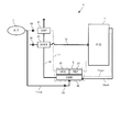
- FIG. 1 is an explanatory view conceptually showing the configuration of a fuel cell system according to an embodiment of the present invention.
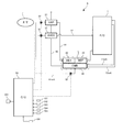
- FIG. 2 is an explanatory view showing a specific configuration of the above fuel cell system.
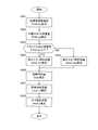
- FIG. 3 is a flow chart showing the flow of start control of the fuel cell system.
- FIG. 4 is a flowchart showing the flow of processing in the power generation heating mode.
- FIG. 5 is an explanatory view showing the relationship between the current and voltage of the fuel cell stack according to the temperature.
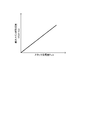
- FIG. 6 is an explanatory view showing the relationship between the current and the calorific value of the fuel cell stack.
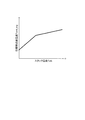
- FIG. 7 is an explanatory view showing the relationship between the temperature of the fuel cell stack and the target power generation amount.
- FIG. 1 is an explanatory view conceptually showing the configuration of a fuel cell system according to an embodiment of the present invention.
- FIG. 2 is an explanatory view showing a specific configuration of the above fuel cell system.
- FIG. 3 is a flow chart showing the flow of start control
- FIG. 8 is an explanatory view showing the relationship between the main fuel flow rate and the sub fuel flow rate at the time of system stop and at the time of power generation.
- FIG. 9 is an explanatory view showing the relationship between the amount of power generation of the fuel cell stack and the main fuel flow rate.
- FIG. 10 is an operation explanatory view (PRD1) of start control.
- FIG. 11 is an operation explanatory view (PRD4) of start control.
- FIG. 12 is an operation explanatory diagram of control at normal time after activation.
- Figure 13 is a time chart showing changes of the combustor temperature T cmb, stack temperature T stk and fuel flow m Fuel (main fuel flow rate m Fuel_m, sub fuel flow m fuel_s) in the startup control.
- FIG. 14 is a flowchart showing a flow of start control of a fuel cell system according to another embodiment of the present invention.
- FIG. 15 is an explanatory view showing the relationship between the temperature of the fuel cell stack and the target combustor temperature
- FIG. 1 conceptually shows the configuration of a fuel cell system S according to an embodiment of the present invention.
- a fuel cell system (hereinafter referred to as “fuel cell system” and may be simply referred to as “system”) S according to the present embodiment includes a fuel cell stack 1, a fuel processing unit 2, an oxidant gas heating unit 3, A combustor 4 and a control unit 5 are provided.
- a fuel cell stack (hereinafter sometimes simply referred to as "stack") 1 is configured by stacking a plurality of fuel cells or fuel cell unit cells, and each fuel cell serving as a power source is, for example, a solid oxide type It is a fuel cell (SOFC).
- Fuel cell stack 1 includes, in an anode system, an anode gas passage 11 for supplying a fuel gas to the anode electrode of the fuel cell, and an anode off gas passage 11 exh for flowing an anode off gas after a power generation reaction discharged from the anode electrode.
- a cathode gas passage 12 for supplying an oxidant gas to the cathode electrode of the fuel cell in the cathode system, and a cathode off gas after power generation reaction discharged from the cathode electrode in the cathode system.
- a cathode off gas passage 12 exh (not shown) for flowing the
- the fuel processing unit 2 is for processing a raw fuel which is a primary fuel to generate a fuel gas used for a power generation reaction in a fuel cell.
- the fuel processor 2 is interposed in the anode gas passage 11, and receives the supply of raw fuel (arrow A1).
- the oxidant gas heating unit 3 is for heating the oxidant gas.
- the oxidant gas heating unit 3 is interposed in the cathode gas passage 12 and receives the supply of oxidant gas (arrow B).
- the oxidant gas is, for example, air, and oxygen used for a power generation reaction can be supplied to the cathode electrode by supplying air in the atmosphere to the cathode electrode of the fuel cell.
- Suction of oxidant gas or air from the atmosphere to the cathode gas passage 12 is carried out, for example, by an air suction means 6 such as an air compressor or blower installed near the open end of the cathode gas passage 12.
- reaction involved in power generation at the anode and cathode of the solid oxide fuel cell can be represented by the following equation.
- the combustor 4 burns the raw fuel of the fuel cell to generate combustion gas.
- the combustor 4 receives the supply of the raw fuel (arrow A2) and receives the supply of the raw fuel oxidant (arrow C).
- the amount of heat generated by the combustion is supplied to the fuel processing unit 2 and the oxidant gas heating unit 3 and used to heat the raw fuel and the oxidant gas.
- FIG. 1 shows the transfer of heat from the combustor 4 to the fuel processor 2 and the oxidant gas heater 3 by thick dotted lines.
- the fuel cell stack 1 itself is not targeted for direct heating by the combustion gas, but the invention is not limited to this, and combustion may be performed by putting the combustor 4 and the fuel cell stack 1 in a common heat insulating case. It is also possible to configure so that the heat quantity of the gas is directly transmitted to the fuel cell stack 1.
- the control unit 5 controls the supply of the raw fuel to the fuel processing unit 2 and the combustor 4 and can be configured to include an electronic control unit.
- the control unit 5 is configured to supply the raw fuel to the controller 4 configured as an electronic control unit, the main fuel supply unit 52 for supplying the raw fuel to the fuel processing unit 2, and the combustor 4.
- the sub-fuel supply unit 53 of The fuel supply units 52 and 53 may both be injectors, and in the present embodiment, the main fuel supply unit 52 includes a first fuel injector, and the sub fuel supply unit 53 includes a second fuel injector.
- the first fuel injector 52 and the second fuel injector 53 operate in response to a command signal from the controller 51, and can continuously or intermittently supply the raw fuel to the fuel processor 2 and the combustor 4.
- the controller 51 determines whether or not the fuel cell stack 1 or the fuel cell is in a state capable of generating power. This determination can be performed based on, for example, the temperature of the fuel cell stack 1.
- the controller 51 supplies raw fuel to the fuel processing unit 2 through the first fuel injector 52 and supplies raw fuel to the combustor 4 through the second fuel injector 53 when the fuel cell stack 1 is in a state capable of generating power. Do. That is, when the temperature of the fuel cell stack 1 rises after the start of the start, and power generation becomes possible, the fuel cell stack 1 starts power generation, and both the fuel processing unit 2 and the combustor 4 Supply. As a result, the fuel cell stack 1 is heated by the amount of heat generated by power generation, and the combustion gas generated by the combustor 4 can also be used as a heat source to promote the warm-up of the fuel cell stack 1.
- the control unit 5 configures a “supply control unit” and a “power generation control unit” according to the present embodiment.
- FIG. 2 shows a specific configuration of the fuel cell system S.
- the fuel cell system S includes a solid oxide fuel cell (SOFC) as a power source, and includes a fuel tank 7 that can be mounted on a vehicle.
- the raw fuel which is the primary fuel is a mixture of oxygenated fuel (for example, ethanol) and water, and is stored in the fuel tank 7.
- the fuel tank 7 and the fuel cell stack 1 are connected via the anode gas passage 11, and the evaporator 21, the fuel heat exchanger 22, and the reformer are connected to the anode gas passage 11 sequentially from the upstream side with respect to the flow direction. 23 are interspersed.
- a branch fuel passage 11sub branches from the anode gas passage 11 on the upstream side of the evaporator 21, and the branch fuel passage 11sub is connected to the combustor 41.
- a first fuel injector 52 is interposed in the anode gas passage 11 between the branch point of the branch fuel passage 11sub and the evaporator 21, and a second fuel injector 53 is interposed in the branch fuel passage 11sub.
- the evaporator 21 receives a supply of an aqueous ethanol solution, which is a raw fuel, from the fuel tank 7 and heats it to evaporate both ethanol and water to produce ethanol gas and water vapor.
- an aqueous ethanol solution which is a raw fuel
- the fuel heat exchanger 22 receives the amount of heat of the combustion gas from the combustor 41 and heats the ethanol gas and the steam.
- the reformer 23 incorporates a reforming catalyst and generates hydrogen by steam reforming from ethanol in a gaseous state.
- Steam reforming can be represented by the following equation. Steam reforming is an endothermic reaction, and it is necessary to supply heat from the outside at the time of reforming.
- the remaining fuel in the anode off gas is burned by the combustor 41 also during reforming, and the heat quantity of the combustion gas is supplied to the reformer 23.
- the fuel gas of the fuel cell is a mixed gas of hydrogen and carbon dioxide generated by reforming ethanol.
- the oxidant gas heating unit 3 includes an air heat exchanger 31 and heats the oxidant gas flowing through the cathode gas passage 12 by heat exchange with the combustion gas supplied from the combustor 41 through the combustion gas passage 42.
- an air compressor 61 is installed near the open end of the cathode gas passage 12, and air in the atmosphere as the oxidant gas is drawn into the cathode gas passage 12 through the air compressor 61.
- the drawn air is heated from normal temperature (for example, 25 ° C.) when passing through the air heat exchanger 31, and is supplied to the fuel cell stack 1.
- the combustor 41 incorporates a combustion catalyst, receives supply of an aqueous ethanol solution which is a raw fuel through the branched fuel passage 11sub, and generates combustion gas by catalytic combustion of ethanol.
- the combustor 41 and the evaporator 21 are connected via the combustion gas passage 42, while the fuel heat exchanger 22 and the reformer 23 are housed in the heat insulating case shared with the combustor 41 (2
- the quantity of heat of the combustion gas is transmitted to the fuel heat exchanger 22 and the reformer 23 inside the common case L, which is indicated by the dotted line L).
- the combustor 41 is connected to both the anode off gas passage 11 exh and the cathode off gas passage 12 exh extending from the fuel cell stack 1, and when the fuel cell system S starts up, the combustor 41 is connected via the cathode off gas passage 12 exh It is possible to supply an oxidant gas to C.41. Furthermore, when reforming the raw fuel, the anode off gas and the cathode off gas are supplied to the combustor 41, and the remaining fuel (ethanol) in the anode off gas is reacted with the oxygen remaining in the cathode off gas over the catalyst. It is possible to heat the evaporator 21, the fuel heat exchanger 22 and the reformer 23.
- the power generated by the fuel cell stack 1 can be used to charge a battery or drive an external device such as an electric motor or a motor generator.
- the fuel cell system S can be applied to a drive system for a vehicle, and the battery generated by the rated operation of the fuel cell stack 1 is charged to the battery, and the battery is powered according to the target driving force of the vehicle. Supply to the motor generator for traveling.
- the controller 51 controls the operation of the first fuel injector 52, the second fuel injector 53, the air compressor 61, and various devices or components required to operate the fuel cell system S.
- the controller 51 is configured as an electronic control unit including a microcomputer including a central processing circuit, various storage devices such as a ROM and a RAM, an input / output interface and the like.
- the controller 51 sets the supply flow rate (hereinafter referred to as “normal supply flow rate”) of the raw fuel required for the rated operation of the fuel cell stack 1 during normal operation (hereinafter simply referred to as “normal time”).
- the raw fuel of the supply flow rate is supplied to the fuel cell stack 1 through the first fuel injector 52.
- the normal operation refers to the operation after the fuel cell stack 1 is completely warmed up
- the rated operation of the fuel cell stack 1 refers to the operation at the maximum power generation output of the fuel cell stack 1.
- the controller 51 detects the generation request of the start of the fuel cell system S based on the signal from the start switch 106, the controller 51 executes start control for warming up the fuel cell stack 1.
- the warm-up of the fuel cell stack 1 refers to raising the temperature of the fuel cell stack 1 that was at a low temperature (for example, normal temperature) while the fuel cell stack 1 is stopped to its operating temperature.
- the operating temperature of the solid oxide fuel cell is about 800 to 1000.degree.
- the controller 51 detects the oxidant gas temperature T cth A signal from the oxidant gas temperature sensor 103, a signal from the reformer temperature sensor 104 that detects the reformer temperature T ref , a signal from the combustor temperature sensor 105 that detects the combustor temperature T cmb, and the like are input.
- the stack temperature T stk is an index indicating the temperature of the fuel cell stack 1 or the fuel cell, and in the present embodiment, the stack temperature sensor 101 is installed near the cathode off gas outlet of the fuel cell stack 1 and detected by the stack temperature sensor 101 Let the stack temperature T stk be the stack temperature.
- the air flow rate m air is the flow rate of the oxidant gas supplied to the fuel cell stack 1.
- an air flow sensor 102 is installed between the cathode gas passage 12, specifically, the air compressor 61 and the air heat exchanger 31, and the air flow m air is detected by the flow detected by the air flow sensor 102. I assume.
- the oxidant gas temperature T cth is adopted as a temperature having a correlation with the inlet temperature of the fuel cell stack 1, and in the present embodiment, the oxidant gas temperature sensor 103 is installed near the oxidant gas inlet of the fuel cell stack 1. The temperature detected by the oxidant gas temperature sensor 103 is taken as the oxidant gas temperature T cth .
- the reformer temperature T ref is an index indicating the temperature of the catalyst provided in the reformer 23.
- the reformer temperature sensor 104 is installed in the anode gas passage 11 on the downstream side of the reformer 23.
- the temperature detected by the reformer temperature sensor 104 in other words, the temperature of the fuel gas generated by the reforming, is taken as the reformer temperature T ref .
- the combustor temperature T cmb is the temperature of the combustion gas generated by the combustor 4, and in the present embodiment, the combustor temperature sensor 105 is installed in the combustion gas passage 42 between the combustor 41 and the air heat exchanger 31. The temperature detected by the combustor temperature sensor 105 is set as the combustor temperature T cmb .
- FIG. 3 is a flowchart showing a flow of start control of the fuel cell system S according to the present embodiment.
- the controller 51 is programmed to execute start control of the fuel cell system S according to the flowchart shown in FIG. 3 when the start request signal is input from the start switch 106 based on the operation of the start switch 106 by the driver.
- the controller 51 starts the start control in response to the input of the start request signal, and ends the determination that the fuel cell stack 1 or the fuel cell has been warmed up.
- the air compressor 61 is operated.
- air in the atmosphere is drawn into the cathode gas passage 12 and supplied to the cathode of the fuel cell stack 1 via the air heat exchanger 31.
- the stack temperature T stk reads the air flow rate m air and the oxidizing gas temperature T cth.
- S103 it is determined whether the fuel cell stack 1 is in a state capable of generating power. Specifically, after the start control is started, it is determined whether the stack temperature Tstk rises and the power generation lower limit temperature of the fuel cell stack 1 (hereinafter referred to as "power generation start temperature") T1 is reached. If the stack temperature Tstk has reached the power generation start temperature T1, the process proceeds to S104, and if not, the process proceeds to S105.
- the power generation start temperature T1 is 500 ° C., for example.
- the power generation heating mode is selected and executed as the operation mode at the time of warm-up.
- the power generation heating mode is an operation mode that mainly uses the amount of heat generated by the power generation of the fuel cell stack 1.
- the controller 51 controls the power conversion device 201 (FIG. 1) interposed between the fuel cell stack 1 and the battery or accessory to execute the output from the fuel cell stack 1.
- an air compressor 61 can be illustrated as an auxiliary machine.
- the combustion heating mode is selected and executed as the operation mode at the time of warm-up.
- the combustion heating mode is an operation mode that mainly uses the amount of heat generated by the combustion in the combustor 41.
- S106 it is determined whether the fuel cell stack 1 has been warmed up. Specifically, it is determined whether or not has reached a predetermined temperature T wup for stack temperature T stk to determine the completion of warming up. If stack temperature T stk has reached the predetermined temperature T wup, as warming up the fuel cell stack 1 has been completed, and terminates the start control, it shifts to the normal control when. Under normal conditions, the fuel cell stack 1 is operated at the rated output. If the temperature has not reached the predetermined temperature T wup , the process returns to S102, and the air compressor 61 is continued to operate, while the processes of S102 to S105 are repeated.
- FIG. 4 is a flowchart showing the flow of processing in the power generation heating mode (S104 in FIG. 3).
- a target temperature (hereinafter referred to as "target combustor temperature”) T cmb_trg of the combustor 41 is calculated.
- the target combustor temperature T cmb_trg is a target temperature of the combustion gas generated by the combustor 41, and is calculated based on the stack temperature T stk .
- the stack temperature which is the temperature near the cathode off gas outlet of the fuel cell stack 1, Calculated by adding the temperature difference ⁇ T stk_set and ⁇ T ahx_set to T stk .
- the temperature difference ⁇ T stk_set is a set value of the temperature difference between the oxidant gas inlet of the fuel cell stack 1 and the cathode off gas outlet (hereinafter referred to as “stack inlet / outlet temperature difference”)
- the temperature difference ⁇ T ahx_set is a set value of the temperature difference between the combustion gas inlet of the air heat exchanger 31 and the oxidant gas outlet.
- the temperature difference ⁇ T stk_set is a temperature difference (eg, 300 ° C.) which is acceptable from the viewpoint of the heat load on the fuel cell
- the temperature difference ⁇ T ahx_set is given by the air heat exchanger 31 at the rated operation of the fuel cell stack 1. It is a temperature difference (for example, 150 ° C.).
- T cmb_trg T stk + ⁇ T stk_set + ⁇ T ahx_set (3)
- a target power generation amount (hereinafter referred to as "target stack power generation amount") Pstk_trg of the fuel cell stack 1 is calculated.
- the target stack power generation amount Pstk_trg is set to the maximum power generation amount that can be output by the fuel cell stack 1 according to the temperature thereof, and the calculation thereof is performed, for example, by searching from table data of the tendency shown in FIG.
- Target stack power generation amount P Stk_trg is set to a greater value as when the stack temperature T stk high.
- FIG. 5 shows the current-voltage characteristics of the fuel cell stack 1.
- the characteristic at low temperature is indicated by a thin solid line L1
- the characteristic at high temperature or in a normal state is indicated by a thick solid line Lh.
- the fuel cell stack 1 recovers its characteristics as the temperature rises, and the current I stk at the lower limit voltage Vmin at which power can be generated also increases.
- FIG. 6 shows the relationship between the current I stk of the fuel cell stack 1 and the calorific value H stk .
- the stack heat generation amount H stk tends to increase as the current I stk increases, in other words, as the voltage V stk decreases. Therefore, the stack heat generation amount Hstk is maximized when the fuel cell stack 1 is caused to generate power at the lower limit voltage Vmin. From the trends shown in FIGS. 5 and 6, it is possible to obtain the relationship shown in FIG.
- the stack inlet / outlet temperature difference ⁇ T stk is equal to or less than a predetermined value ⁇ T1.
- the process proceeds to S204, and when the temperature difference ⁇ T stk exceeds the predetermined value ⁇ T1, the process proceeds to S205.
- the predetermined value ⁇ T1 is, for example, an allowable upper limit value ⁇ T stk_set (for example, 300 ° C.) of the temperature difference.
- the flow rate (hereinafter referred to as "main fuel flow rate”) m fuel_m of the raw fuel supplied through the first fuel injector 52 is set to the minimum main fuel flow rate m fuel_min .
- Minimum main fuel flow rate m Fuel_min compared decrease a supply flow rate of the raw fuel, as a possible lower limit suppress degradation caused in the fuel cell stack 1 can be set in advance by adaptation through experiment or the like.
- fuel starvation deterioration of the electrode due to a shortage of fuel gas
- the raw fuel supplied to the fuel processing unit 2 accounts for the flow rate of the raw fuel (hereinafter referred to as “total raw fuel flow rate”) m fuel_ttl supplied to the entire system at warm-up.
- the ratio is the smallest, in other words, the ratio of the raw fuel supplied to the combustor 41 is the largest.
- the relationship between the main fuel flow rate m Fuel_m and sub fuel flow m Fuel_s shows for each of when the system is stopped (the power before starting) and power generation.
- the minimum main fuel flow rate m Fuel_min is set to a constant value.
- the amount of heat recovered by the anode gas flowing through the fuel processing unit 2 (hereinafter referred to as “the amount of exhaust heat recovery”) Q rec of the heat amount of the fuel gas is calculated.
- Heat recovery amount Q rec is generally because they have a tendency to increase with increasing main fuel flow rate m Fuel_m, can be calculated as a function of the main fuel flow rate m fuel_m. Not limited to this, the exhaust heat recovery amount Q rec may be set as a constant value.
- the total raw fuel / fuel flow rate m fuel — ttl is calculated.
- the calculation of the raw fuel total flow rate m fuel — ttl is according to the following equation.
- the following equation basically indicates that the heat balance in the whole system is balanced, with the amount of heat introduced by the supply of the raw fuel through the first and second fuel injectors 52, 53 as an input.
- m fuel_ttl A / B (4.1)
- A m air x ⁇ h air (T cmb )-h air (T stk ) ⁇ + m h2 c x ⁇ h h2 (T stk )-h h2 o (T stk ) ⁇ -Q rec ...
- m fuel_ttl Raw fuel total flow rate (molar ratio converted value)
- m air Molar flow of air
- m h 2 c Hydrogen consumption by power generation
- Q rec Exhaust heat recovery amount of anode gas
- T stk Exit temperature of fuel cell stack
- T cmb Temperature of combustion gas
- T fuel Temperature of raw fuel h air (T): Enthalpy h c2h5ohl (T) in air: Enthalpy h h2ol (T) in ethanol (liquid): Enthalpy h co2 (T) in water (liquid): Enthalpy h carbon dioxide (T): Water (gas) enthalpy h o2 of) (T): enthalpy above equation oxygen (4.2) is the mass transfer content inside the fuel cell stack 1 (specifically, oxygen transfer partial 2m H2C ⁇ between the electrodes due to power generation Considering h o2 (T stk )), it can be expressed
- A m air ⁇ ⁇ h air (T cmb) -h air (T stk) ⁇ - 2m h2c ⁇ h o2 (T stk) + ⁇ 2m h2c ⁇ h o2 (T stk) -Q rec -Q stk ⁇ -P ... (4.2a)
- Q stk variation in calorific value of anode gas inside fuel cell stack 1
- P amount of power generation
- Q stk exemplify heat reception of anode gas by power generation of fuel cell stack 1 and heat absorption by internal reforming Can.
- the following relationship may be taken into consideration when calculating the raw fuel total flow rate m fuel — ttl .
- the following equation shows that the heat balance of the anode gas is balanced between the input and output of the fuel cell stack 1.
- the following equation shows the variation of heat of the anode gas in the fuel cell stack 1, the right side third and fourth terms of the equation (4.2a) ( ⁇ 2m h2c ⁇ h o2 (T stk) -Q rec It is possible to approximate -Q stk ⁇ -P).
- C D (5.1)
- C m fuel_m ⁇ ⁇ (1/5 ) ⁇ h c2h5ohl (T fuel) + (4/5) ⁇ h h2ol (T fuel) ⁇ + ⁇ 2m h2c ⁇ h o2 (T stk) -Q rec -Q stk ⁇ -P ...
- the controller 51 sets a command signal corresponding to the main fuel flow rate m Fuel_m and sub fuel flow m Fuel_s, the first fuel injector 52, and outputs to the drive circuit of the second fuel injectors 53.
- the controller 51, the first fuel injector 52, and the second fuel injector 53 constitute a "supply control unit", and the controller 51 constitutes a "power generation control unit”.
- the function of the “power generation control unit” is embodied as the process (control of the power conversion device) of S104 of the flowchart shown in FIG. 3, and the whole of S102 to 104 of the flowchart shown in FIG.
- the function of the "supply control unit” is embodied.
- the function of "warm-up target flow rate setting unit” is embodied as the process of S102 of the flowchart shown in FIG. 3 and S201 to S207 of the flowchart shown in FIG.
- the function of the "gas temperature setting unit” is embodied, and the function of the "fuel cell temperature detection unit” is embodied as the process of S102 shown in FIG. Furthermore, the execution time of the process shown in S204 of the flowchart shown in FIG. 4 corresponds to the "second supply mode", and the execution time of the process shown in S205 corresponds to the "first supply mode”.
- FIG. 10 shows the operation at startup (before the start of power generation by the fuel cell stack 1)
- FIG. 11 shows the operation after the start of power generation at startup
- FIG. 12 shows the operation at normal times after startup. There is.
- the passage through which the gas actually flows is shown by a thick solid line
- the passage through which the flow of the gas is stopped is shown by a thin dotted line.
- FIG. 13 shows the operation of the fuel cell system S at start-up (PRD1 to PRD4) in a time chart.
- the upper part of the figure shows changes in the combustor temperature T cmb , the reformer temperature T ref and the stack temperature T stk
- the lower part of the same figure shows the change of the fuel flow rate m fuel respectively.
- the lower time chart indicated by the solid line of the main fuel flow rate m Fuel_m it shows by dashed lines the sub fuel flow m fuel_s.
- a period PRD1 indicates a period in which the reformer 23 is not in a reformable state
- periods PRD2 to PRD4 indicate a period in which the reformer 23 is in a reformable state.
- Periods PRD1 to PRD3 indicate periods in which the fuel cell stack 1 can not generate power
- period PRD4 indicates a period in which the fuel cell stack 1 can generate power.
- the temperature of the combustor 41 (combustor temperature T cmb ) is limited to the combustor upper limit temperature T cmb_max or less throughout the startup control.
- the limitation of the combustor temperature T cmb is, for example, by limiting the target combustor temperature T cmb_trg set by the process of S201 shown in FIG. 4 to the combustor upper limit temperature T cmb_max or less.
- the upper limit temperature at which the deterioration of the catalyst (for example, the oxidation catalyst) provided in the combustor 41 can be suppressed can be exemplified as the combustor upper limit temperature T cmb_max .
- the air taken in the cathode gas passage 12 by the air compressor 61 is heated by the air heat exchanger 31 by heat exchange with the combustion gas, and the air after heating is supplied to the fuel cell stack 1 to make the fuel cell stack 1 Heat up.
- warm-up of the fuel cell stack 1 proceeds, and the stack temperature Tstk rises (FIG. 13).
- the cathode off gas (oxidant gas) discharged from the fuel cell stack 1 is led to the combustor 41 via the cathode off gas passage 12exh, and the remaining oxygen in the cathode off gas is used as an oxidant for the raw fuel.
- the reformer temperature T ref is further increased, the raw fuel total flow rate m Fuel_ttl is below the rated flow m fuel_rtd (time t2), the supply of the raw fuel through the second fuel injector 53 is stopped, the raw fuel Total The raw fuel with the flow rate m fuel — ttl is supplied to the reformer 23 through the first fuel injector 52 (FIG. 13, period PRD3).
- the fuel cell stack 1 is caused to generate power, and raw fuel is generated through both the first and second fuel injectors 52 and 53. Supply. Specifically, the switch circuit (not shown) of the junction box provided between fuel cell stack 1 and power converter 201 (FIG. 2) is closed to start output from fuel cell stack 1.
- the raw fuel of the flow (minimum main fuel flow m fuel_min or maximum main fuel flow m fuel_max ) according to the stack inlet / outlet temperature difference ⁇ T stk is supplied through the first fuel injector 52 while the shortage with respect to the total raw fuel flow m fuel_ttl A minute amount of raw fuel is supplied through the second fuel injector 53.
- the combustion gas generated by the combustor 41 is controlled to the target temperature while promoting the warm-up by actively utilizing the self-heating by the power generation of the fuel cell stack 1, and it is necessary for the reforming. It is possible to heat up the fuel cell stack 1 by heating the fuel cell stack 1 together with the heat of the combustion gas.
- the main fuel flow rate m Fuel_m is increased with increasing stack temperature T stk, elevated is restricted more than the rated flow rate m fuel_rtd (time t4). That is, at the time of warm-up, although the increase of the raw fuel total flow m fuel_ttl exceeding the rated flow m fuel_rtd is permitted, the main fuel flow m fuel_m is limited to the rated flow m fuel_rtd or less.
- the fuel cell system S according to the present embodiment is configured as described above, and the operation and effects obtained by the present embodiment will be described below.
- the fuel cell stack 1 when starting up the fuel cell system S, it is determined whether the fuel cell stack 1 is in a state capable of generating power, specifically, whether the stack temperature T stk has reached the power generation start temperature T1.
- the stack temperature Tstk reaches the power generation start temperature T1
- the fuel cell stack 1 is caused to generate power, and the raw fuel is supplied through both the first and second fuel injectors 52, 53.
- the fuel flow rate (the total raw fuel flow m fuel_ttl ) increases with the progress of warm-up. It is possible to heat the fuel cell stack 1 with a large amount of heat and realize rapid warm-up, while suppressing the enlargement of the processing unit (for example, the reformer 23) and the combustor 41.
- the exhaust heat recovery amount Q rec of the anode gas and the power generation amount P stk of the fuel cell stack 1 are taken into account. allowing proper setting of the feed rate of the raw fuel (sub fuel flow rate m fuel_s) and then, the temperature of the combustion gas can be prevented from rising excessively. Thus, the deterioration of the combustor 41 can be suppressed, and the fuel cell stack 1 can be prevented from being subjected to an excessive heat load due to the expansion of the stack inlet / outlet temperature difference ⁇ Tstk .
- the target combustor temperature T cmb_trg based on the stack temperature T stk , it becomes possible to set the target combustor temperature T cmb_trg appropriately in accordance with the progress of the warm-up. Furthermore, the calculation load of the controller 51 at the setting of the target combustor temperature T cmb_trg can be reduced.
- the ratio of the main fuel flow rate m fuel _m to the total raw fuel flow rate m fuel _ttl is switched according to the stack inlet / outlet temperature difference ⁇ T stk .
- the stack inlet / outlet temperature difference ⁇ T stk is relative If the difference is smaller, the minimum main fuel flow rate m fuel_min that reduces the ratio is set (S 204), while if the stack inlet / outlet temperature difference .DELTA.T stk is relatively large, the maximum main fuel flow rate m fuel_max increases the ratio.
- S205 exhaust heat recovery by the anode gas can be promoted and warm-up can be promoted while suppressing the expansion of the stack inlet / outlet temperature difference ⁇ T stk .
- the heat generation amount H stk by the power generation of the fuel cell stack 1 is maximized to promote warm-up. It is possible to reduce the time required for activation.
- FIG. 14 shows a flow of start control (power generation heating mode) of a fuel cell system according to another embodiment of the present invention.
- the configuration of the entire system may be the same as in the previous embodiment shown in FIG. 2, and the controller 51 starts the start control when the start request signal is input from the start switch 106. According to the same flow as shown in, the generation heating mode or the combustion heating mode is selected.
- the S301 When the power heating mode is selected, the S301, and calculates the target stack power generation amount P Stk_trg based on stack temperature T stk. Specifically, the same processing as that of S202 in the flowchart shown in FIG. 4 is performed.
- a target combustor temperature T cmb_trg is calculated.
- the temperature is calculated based on the outlet temperature of the fuel cell stack 1 (for example, the stack temperature T stk ) as a temperature for suppressing excessive temperature rise of the combustor 41.
- the stack inlet / outlet temperature The temperature can be calculated based on the inlet temperature of the fuel cell stack 1 (for example, the oxidant gas temperature T cth ) as the temperature for suppressing the expansion of the difference ⁇ T stk .
- the target combustor temperature T cmb_trg is calculated as a temperature according to the stack temperature T stk by searching from table data of the tendency shown in FIG.
- the target combustor temperature T cmb_trg is set to a larger value as the stack temperature T stk is higher.
- a target combustor temperature T cmb_trg preset as a temperature giving the oxidant gas temperature Tcth is calculated.
- the calculation time can be shortened by searching the table data as in S303.
- the raw fuel total flow rate m fuel — ttl is calculated.
- the difference between the target combustor temperature T cmb_trg and the combustor temperature T cmb (the temperature detected by the combustor temperature sensor 105) is input to a feedback controller such as a PI controller (not shown), and the difference is 0
- the correction amount to be close to is added to the raw fuel total flow rate m fuel — ttl .
- the fuel flow rate m Fuel_m while simplifying the calculation of m Fuel_s, it is possible to contribute to the realization of the rapid warm-up.
Landscapes
- Engineering & Computer Science (AREA)
- Chemical & Material Sciences (AREA)
- Life Sciences & Earth Sciences (AREA)
- Manufacturing & Machinery (AREA)
- Sustainable Development (AREA)
- Sustainable Energy (AREA)
- Chemical Kinetics & Catalysis (AREA)
- Electrochemistry (AREA)
- General Chemical & Material Sciences (AREA)
- Combustion & Propulsion (AREA)
- Fuel Cell (AREA)
Abstract
La présente invention concerne un système de pile à combustible, équipé: d'une pile à combustible; d'une unité de traitement de combustible qui traite un combustible brut et génère un gaz combustible pour la pile à combustible; d'une unité de chauffage de gaz oxydant qui chauffe un gaz oxydant pour la pile à combustible; une chambre de combustion qui brûle le combustible brut et génère un gaz de combustion pour chauffer l'unité de traitement de combustible et l'unité de chauffage de gaz oxydant; d'une unité de commande d'alimentation qui, lors du chauffage de la pile à combustible, contrôle l'alimentation en combustible brut vers l'unité de traitement de combustible et vers la chambre de combustion; et d'une unité de commande de génération d'énergie qui commande la génération d'énergie pendant le chauffage de la pile à combustible. Lorsque la pile à combustible a atteint une température d'activation de génération d'énergie, l'unité de commande de génération d'énergie entraîne la génération d'énergie par la pile à combustible, et l'unité de commande d'alimentation fournit le combustible brut à l'unité de traitement de carburant et à la chambre de combustion.
Priority Applications (5)
| Application Number | Priority Date | Filing Date | Title |
|---|---|---|---|
| EP17927767.8A EP3691009B1 (fr) | 2017-09-29 | 2017-09-29 | Système de pile à combustible et procédé de commande de système de pile à combustible |
| US16/648,052 US11695130B2 (en) | 2017-09-29 | 2017-09-29 | Fuel cell system and fuel cell system control method |
| JP2019544141A JP6943285B2 (ja) | 2017-09-29 | 2017-09-29 | 燃料電池システムおよび燃料電池システムの制御方法 |
| CN201780095427.6A CN111164812B (zh) | 2017-09-29 | 2017-09-29 | 燃料电池系统和燃料电池系统的控制方法 |
| PCT/JP2017/035636 WO2019064539A1 (fr) | 2017-09-29 | 2017-09-29 | Système de pile à combustible et procédé de commande de système de pile à combustible |
Applications Claiming Priority (1)
| Application Number | Priority Date | Filing Date | Title |
|---|---|---|---|
| PCT/JP2017/035636 WO2019064539A1 (fr) | 2017-09-29 | 2017-09-29 | Système de pile à combustible et procédé de commande de système de pile à combustible |
Publications (1)
| Publication Number | Publication Date |
|---|---|
| WO2019064539A1 true WO2019064539A1 (fr) | 2019-04-04 |
Family
ID=65903783
Family Applications (1)
| Application Number | Title | Priority Date | Filing Date |
|---|---|---|---|
| PCT/JP2017/035636 Ceased WO2019064539A1 (fr) | 2017-09-29 | 2017-09-29 | Système de pile à combustible et procédé de commande de système de pile à combustible |
Country Status (5)
| Country | Link |
|---|---|
| US (1) | US11695130B2 (fr) |
| EP (1) | EP3691009B1 (fr) |
| JP (1) | JP6943285B2 (fr) |
| CN (1) | CN111164812B (fr) |
| WO (1) | WO2019064539A1 (fr) |
Families Citing this family (4)
| Publication number | Priority date | Publication date | Assignee | Title |
|---|---|---|---|---|
| JP7264932B2 (ja) * | 2021-03-29 | 2023-04-25 | 本田技研工業株式会社 | 燃料電池システムの運転方法および燃料電池システム |
| US20230211887A1 (en) * | 2022-01-04 | 2023-07-06 | General Electric Company | Control of a propulsion system having a fuel cell |
| CN114714925A (zh) * | 2022-04-28 | 2022-07-08 | 重庆金康赛力斯新能源汽车设计院有限公司 | 一种增程器的控制方法、装置和系统 |
| CN117744413B (zh) * | 2024-02-20 | 2024-06-04 | 华北电力大学 | 一种固体氧化物燃料电池电堆换热等效方法、设备及介质 |
Citations (5)
| Publication number | Priority date | Publication date | Assignee | Title |
|---|---|---|---|---|
| JP2007305390A (ja) * | 2006-05-10 | 2007-11-22 | Toyota Motor Corp | 燃料電池システム及びその循環比算出方法 |
| JP2013089497A (ja) * | 2011-10-19 | 2013-05-13 | Honda Motor Co Ltd | 燃料電池モジュール |
| JP2014154424A (ja) * | 2013-02-12 | 2014-08-25 | Nissan Motor Co Ltd | 燃料電池システム |
| JP2016154067A (ja) | 2015-02-20 | 2016-08-25 | 本田技研工業株式会社 | 燃料電池モジュール及びその運転方法 |
| JP2017010875A (ja) * | 2015-06-25 | 2017-01-12 | トヨタ自動車株式会社 | 燃料電池システム |
Family Cites Families (3)
| Publication number | Priority date | Publication date | Assignee | Title |
|---|---|---|---|---|
| CN101512815B (zh) * | 2006-09-27 | 2011-06-08 | 松下电器产业株式会社 | 燃料电池系统 |
| JP5408420B2 (ja) * | 2009-07-30 | 2014-02-05 | 日産自動車株式会社 | 燃料電池システムとこの燃料電池システムに用いる燃料電池の昇温方法 |
| JP5643712B2 (ja) * | 2011-04-14 | 2014-12-17 | 本田技研工業株式会社 | 燃料電池モジュール |
-
2017
- 2017-09-29 WO PCT/JP2017/035636 patent/WO2019064539A1/fr not_active Ceased
- 2017-09-29 US US16/648,052 patent/US11695130B2/en active Active
- 2017-09-29 JP JP2019544141A patent/JP6943285B2/ja active Active
- 2017-09-29 CN CN201780095427.6A patent/CN111164812B/zh active Active
- 2017-09-29 EP EP17927767.8A patent/EP3691009B1/fr active Active
Patent Citations (5)
| Publication number | Priority date | Publication date | Assignee | Title |
|---|---|---|---|---|
| JP2007305390A (ja) * | 2006-05-10 | 2007-11-22 | Toyota Motor Corp | 燃料電池システム及びその循環比算出方法 |
| JP2013089497A (ja) * | 2011-10-19 | 2013-05-13 | Honda Motor Co Ltd | 燃料電池モジュール |
| JP2014154424A (ja) * | 2013-02-12 | 2014-08-25 | Nissan Motor Co Ltd | 燃料電池システム |
| JP2016154067A (ja) | 2015-02-20 | 2016-08-25 | 本田技研工業株式会社 | 燃料電池モジュール及びその運転方法 |
| JP2017010875A (ja) * | 2015-06-25 | 2017-01-12 | トヨタ自動車株式会社 | 燃料電池システム |
Non-Patent Citations (1)
| Title |
|---|
| See also references of EP3691009A4 |
Also Published As
| Publication number | Publication date |
|---|---|
| CN111164812B (zh) | 2022-10-25 |
| EP3691009A1 (fr) | 2020-08-05 |
| EP3691009B1 (fr) | 2024-04-24 |
| US11695130B2 (en) | 2023-07-04 |
| CN111164812A (zh) | 2020-05-15 |
| EP3691009A4 (fr) | 2020-11-11 |
| JP6943285B2 (ja) | 2021-09-29 |
| JPWO2019064539A1 (ja) | 2020-10-22 |
| US20200266460A1 (en) | 2020-08-20 |
Similar Documents
| Publication | Publication Date | Title |
|---|---|---|
| JP3921910B2 (ja) | 燃料電池システム | |
| JP6627887B2 (ja) | 燃料電池システム、及び燃料電池システムの制御方法 | |
| JP6943285B2 (ja) | 燃料電池システムおよび燃料電池システムの制御方法 | |
| JP4147659B2 (ja) | 改質器の制御装置 | |
| JP2018110079A (ja) | 燃料電池システム及びその運転方法 | |
| JP6870737B2 (ja) | 燃料電池システムおよび燃料電池システムの制御方法 | |
| JP3889553B2 (ja) | 燃料電池システムの制御方法およびその装置 | |
| JP3999513B2 (ja) | 燃料電池発電システムおよびその運転方法 | |
| WO2017104211A1 (fr) | Système de pile à combustible et son procédé de commande | |
| JP2017162746A (ja) | 燃料電池システム及びその運転方法 | |
| JP3992423B2 (ja) | 燃料電池システムの運転起動方法およびその装置 | |
| JP7110859B2 (ja) | 燃料電池システムおよび燃料電池システムの運転方法 | |
| JP3562378B2 (ja) | 高分子電解質型燃料電池システム | |
| JP7176263B2 (ja) | 燃料電池システムおよび燃料電池システムの制御方法 | |
| JP4824915B2 (ja) | 燃料電池システム | |
| JPH05303971A (ja) | 溶融炭酸塩型燃料電池発電システム | |
| JP5021895B2 (ja) | 燃料電池発電システム | |
| CN113169363B (zh) | 燃烧系统和燃烧系统的控制方法 | |
| WO2021116725A1 (fr) | Procédé de commande de système de pile à combustible, et système de pile à combustible | |
| JPH0697618B2 (ja) | 燃料電池発電装置 | |
| JP2019079689A (ja) | 燃料電池システムおよび燃料電池システムの制御方法 | |
| JP2001158604A (ja) | 水素発生装置、およびそれを組み込んだ発電装置 | |
| JPH06251789A (ja) | 燃料電池発電設備の温度制御方法 | |
| JPWO2019026146A1 (ja) | 燃料電池システムの制御方法、及び、燃料電池システム |
Legal Events
| Date | Code | Title | Description |
|---|---|---|---|
| 121 | Ep: the epo has been informed by wipo that ep was designated in this application |
Ref document number: 17927767 Country of ref document: EP Kind code of ref document: A1 |
|
| ENP | Entry into the national phase |
Ref document number: 2019544141 Country of ref document: JP Kind code of ref document: A |
|
| NENP | Non-entry into the national phase |
Ref country code: DE |
|
| ENP | Entry into the national phase |
Ref document number: 2017927767 Country of ref document: EP Effective date: 20200429 |