WO2019065743A1 - Système de commande de train - Google Patents
Système de commande de train Download PDFInfo
- Publication number
- WO2019065743A1 WO2019065743A1 PCT/JP2018/035712 JP2018035712W WO2019065743A1 WO 2019065743 A1 WO2019065743 A1 WO 2019065743A1 JP 2018035712 W JP2018035712 W JP 2018035712W WO 2019065743 A1 WO2019065743 A1 WO 2019065743A1
- Authority
- WO
- WIPO (PCT)
- Prior art keywords
- train
- safety
- control system
- following
- ground
- Prior art date
- Legal status (The legal status is an assumption and is not a legal conclusion. Google has not performed a legal analysis and makes no representation as to the accuracy of the status listed.)
- Ceased
Links
Images


Classifications
-
- B—PERFORMING OPERATIONS; TRANSPORTING
- B60—VEHICLES IN GENERAL
- B60L—PROPULSION OF ELECTRICALLY-PROPELLED VEHICLES; SUPPLYING ELECTRIC POWER FOR AUXILIARY EQUIPMENT OF ELECTRICALLY-PROPELLED VEHICLES; ELECTRODYNAMIC BRAKE SYSTEMS FOR VEHICLES IN GENERAL; MAGNETIC SUSPENSION OR LEVITATION FOR VEHICLES; MONITORING OPERATING VARIABLES OF ELECTRICALLY-PROPELLED VEHICLES; ELECTRIC SAFETY DEVICES FOR ELECTRICALLY-PROPELLED VEHICLES
- B60L15/00—Methods, circuits, or devices for controlling the traction-motor speed of electrically-propelled vehicles
- B60L15/40—Adaptation of control equipment on vehicle for remote actuation from a stationary place
-
- B—PERFORMING OPERATIONS; TRANSPORTING
- B61—RAILWAYS
- B61L—GUIDING RAILWAY TRAFFIC; ENSURING THE SAFETY OF RAILWAY TRAFFIC
- B61L23/00—Control, warning or like safety means along the route or between vehicles or trains
- B61L23/08—Control, warning or like safety means along the route or between vehicles or trains for controlling traffic in one direction only
- B61L23/14—Control, warning or like safety means along the route or between vehicles or trains for controlling traffic in one direction only automatically operated
- B61L23/18—Control, warning or like safety means along the route or between vehicles or trains for controlling traffic in one direction only automatically operated specially adapted for changing lengths of track sections in dependence upon speed and traffic density
-
- B—PERFORMING OPERATIONS; TRANSPORTING
- B61—RAILWAYS
- B61L—GUIDING RAILWAY TRAFFIC; ENSURING THE SAFETY OF RAILWAY TRAFFIC
- B61L27/00—Central railway traffic control systems; Trackside control; Communication systems specially adapted therefor
- B61L27/20—Trackside control of safe travel of vehicle or train, e.g. braking curve calculation
- B61L2027/204—Trackside control of safe travel of vehicle or train, e.g. braking curve calculation using Communication-based Train Control [CBTC]
-
- B—PERFORMING OPERATIONS; TRANSPORTING
- B61—RAILWAYS
- B61L—GUIDING RAILWAY TRAFFIC; ENSURING THE SAFETY OF RAILWAY TRAFFIC
- B61L2201/00—Control methods
Definitions
- the present invention relates to a train control system that communicates between a train and a ground facility to operate and control a train, and more specifically, when divided into train formations, prevents collision with a divided counterpart train. It relates to technology.
- Patent Document 1 when setting a merge division permission area between trains and merging or division of trains, there are other trains to be merged or divided in the merge division permission area. If it is, it controls so that the said train is not recognized by the on-board device.
- the present invention has been made in view of the above circumstances, and the object of the present invention is to provide a train control system capable of safe train control even in the approach of trains when the train formation is divided. To provide.
- a train control system is a train control system that communicates between a train and a ground facility to perform operation and control of the train, and in the case of dividing the train formation, the preceding train and the subsequent train It is characterized in that safety areas for division which extend corresponding to the separation distance between the trains and do not overlap with each other are set in the preceding train and the succeeding train, and emergency stop is made when security in the safety area is not secured. .
- the on-vehicle device does not operate the emergency brake by regarding the other train immediately after the division as an approaching train. Then, when the safety in the safe area is not secured, for example, when the other train enters the safe area of the own train, or when the safe area of the own train overlaps with the safe area of the other train, the emergency stop of the own train Can. Therefore, after the division of the train formation, safe train control becomes possible even in a state in which the train approaches and collision with the divided opposite train can be suppressed.
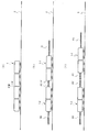
- FIG. 1A and FIG. 1B it is a figure for demonstrating the operation
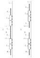
- FIG. 1A and Drawing 1B when division of train organization is performed, it is a figure for explaining operation in the state where a train separated.
- FIG. 1A and 1B respectively show a train control system according to an embodiment of the present invention.
- FIG. 1A is a schematic configuration diagram of the whole system
- FIG. 1B is a configuration diagram of a train.
- radios radio base stations
- 4-1, 4-2,..., 4-n along the track 2 of the train 1 are provided at predetermined positions at predetermined positions, and an antenna is provided.
- Information is transmitted / received by radio communication with the train 1 via 4-1a, 4-2a,..., 4-na, and the train 1 is controlled.
- the ground equipment is configured by the radios 4-1, 4-2,..., 4-n along the ground and the ground device 5.
- the ground device 5 is connected to each of the wayside radios 4-1, 4-2,..., 4-n by wire or wirelessly.
- the ground device 5 includes a train position detection unit 5a, a CBTC control unit 5b, an ATP (Automatic Train Protection) device 5c, a database 5d, and the like.
- a plurality of ground devices 5 are installed in each of the management areas set in track 2, and transmission / reception of information can be performed via a radio along a track belonging to the corresponding management area. It is possible to send and receive information to each other.
- the train position detection unit 5a detects the position of the train 1 based on the communication state between the on-board radios mounted on the train 1 and the radios 4-1, 4-2,. For example, the position of the train 1 is calculated from the propagation time taken for the round trip between the on-train radio and the on-board radio, and the position correction by the ground element is performed to calculate the train 1 Detect the position of Alternatively, a distance detection sensor such as a GPS (Global Positioning System) or an optical distance measurement device may be mounted on the train 1 to detect the position of the train 1. The detected position information of the train is frequently transmitted from the on-board device to the ground device 5 as one of the control information of the train 1.
- GPS Global Positioning System
- the CBTC control unit 5b detects the position and speed of the train 1 based on the position information of the train 1 detected by the train position detection unit 5a and the speed information detected by a speed detector or the like mounted on the train 1. And generate train control information such as driving speed and stop.
- the ATP device 5c detects the presence of the train 1 by receiving the position information from the train 1 by wireless communication.
- the database 5d includes the ID (identification code) of the on-board radio installed in the train 1 with the radios 4-1, 4-2,. I remember.
- an on-board device 6 is mounted on the leading vehicle 1a and an on-vehicle device 7 is mounted on the last vehicle 1b.
- the on-vehicle apparatus 6 is provided with an on-vehicle wireless device 8-1 and a database 9-1
- the on-vehicle apparatus 7 is provided with an on-vehicle wireless device 8-2 and a database 9-2.
- the on-vehicle apparatus 6 and the on-vehicle apparatus 7 perform data communication with each other.
- the same data as the database 5d of the ground device 5 is stored in the databases 9-1 and 9-2, that is, on the cars mounted on the train 1 and the radios 4-1, 4-2,.
- the ID (identification code) of the wireless device, the speed information and the route information of the train 1 and the like are stored.
- the onboard wireless device 8-1 is connected to the antenna 8-1a having directivity toward the traveling direction (forward) of the train 1, and the onboard wireless device 8-2 is in the opposite direction to the traveling direction of the train 1 And the antenna 8-2a having directivity. Then, information is exchanged by wireless communication between the on-board wireless device 8-1 and the along-side wireless device in front of the train 1, and between the on-board wireless device 8-2 and the along-side wireless device behind the train 1. Exchange information by wireless communication.
- the on-board wireless devices 8-1 and 8-2 and the along-side wireless devices 4-1, 4-2,..., 4-n are, for example, ISM (Industry Science Medical) which is a general-purpose wireless band standardized internationally.
- ISM Industry Science Medical
- a general-purpose radio using a 2.4 GHz band called band can be used.
- the onboard radios 8-1 and 8-2 and the on-site radios close to the train 1 establish communication in a one-to-one relationship, and exchange information.
- each on-vehicle radio 8-1 and 8-2 and each along-side radio 4-1, 4-2, ..., 4-n have a self-diagnosis function, and state information of the self-diagnosed radio, That is, information on whether the system is operating normally or is broken is stored in the databases 5d, 9-1 and 9-2 so that the ground device 5 and the on-vehicle devices 6 and 7 share the information.
- the on-board devices 6, 7 are connected to the on-board wireless units 8-1 and 8-2 as the train 1 moves, and each of the on-site wireless units 4-1, 4-2,.
- a handover is performed to sequentially switch the communication state.
- the handover is performed at the position of the on-road radio when the on-board radios 8-1 and 8-2 are close to the along-side radios 4-1, 4-2,. .
- the ground device 5 transmits the train position information wirelessly transmitted from the on-board radios 8-1 and 8-2 of the train 1 to the radios 4-1, 4-2,.
- the train position is detected by the train position detection unit 5a by two trains obtained by two railway radios close to the train 1 among them.
- the CBTC control unit 5b Based on the detected train position, the CBTC control unit 5b generates train control information, and wirelessly transmits the on-vehicle wireless units 8-1 and 8-2 from the two railway radios via the two routes described above. Do.
- the telegrams transmitted by these two paths are basically the same, and the communication paths have redundancy.
- the on-board devices 6 and 7 control the train 1 based on the train control information received by the on-vehicle wireless devices 8-1 and 8-2.
- each train 1-1, 1 is divided between the divided trains (preceding train 1-1 and subsequent train 1-2).
- the safety areas A1 and A2 are used as an approach detection zone for detecting the approach of the train, and are determined by the position error and the speed of the trains 1-1 and 1-2.
- the setting of the safety areas A1 and A2 is performed in the following procedure. First, each of the preceding train 1-1 and the following train 1-2 measures the distance traveled from the closest wayside radio and sends it to the ground apparatus 5 by wireless communication, and the train position detection unit 5a of the ground apparatus 5 precedes it. Detects the position of train 1-1 and following train 1-2.
- the preceding train 1-1 and the following train 1-2 detect the approach of the train into the safe areas A1 and A2 in the direction of each other immediately after the division, and make an emergency stop when the security is not secured. For example, when the following train 1-2 is present in the safety area A1 of the preceding train 1-1 and the preceding train 1-1 is present in the safety area A2 of the following train 1-2, the safety is not secured. When the mutual safety areas A1 and A2 overlap (in this case, it is considered that there is another train). Each train 1-1, 1-2 transmits this information from the on-board radios 8-1 and 8-2 to the ATP device 5 c via the radios 4-1, 4-2,. It transmits, and it is judged whether safety is secured by the ATP device 5c. If it is determined that the safety is not secured by the ATP device 5c, the preceding train 1-1 and / or the following train 1-2 are emergency stopped according to the situation.
- the traveling control with the normal ATP pattern is performed on the preceding train 1-1 and the following train 1-2 immediately after the division. That is, the preceding train 1-1 sets the safety buffer B1 in the normal direction in the forward direction (the original traveling direction) to detect whether there are other trains in the traveling line range immediately after the division etc. Run a normal ATP pattern to confirm the safety of the course.
- the succeeding train 1-2 sets the normal safety buffer B2 to the rear, and checks the presence of the existing line for the rear existing range immediately after the division.
- EB Ergency Brake
- the setting of the safety buffer and the presence / absence detection of other trains in the safety buffer described above are premised on transmitting information required by each train to the ATP device 5c and determining and determining the ATP device 5c.
- this ATP device 5c has been described by taking the case where it is provided in the ground device 5 as an example, it may be provided in the on-vehicle devices 6, 7.
- the “ATP pattern” is an operating system that is calculated based on the information of the remaining distance to the position where the train must stop in the system of ATP, as an operation curve that can be realized by the braking performance of the train ( Brake pattern).
- the term "safety buffer” means the conceptual range that each train has. That is, it is an error between the position of the train detected by the system and the position where the train actually exists, and there is an error in the distance traveled and an error in the data transmission delay.
- the on-vehicle devices 6 and 7 calculate the position detection error and the travel distance error of the position correction ground element arranged on the ground on the vehicle.
- the calculation result is sent to the ground device 5 by wireless communication, and the ground device 5 side corrects an error due to a delay in data transmission to set a safety buffer. Then, when there is another train within this range, it is recognized that a nearby train is present, and processing for instructing the on-board device 6 or 7 that has detected the nearby train from the ground device 5 to perform an emergency stop To be executed.
- the safety areas A1 and A2 of the preceding train 1-1 and the following train 1-2 are extended (indicated by A1 ′ and A2 ′) so as not to overlap with each other as the preceding train 1-1 travels. Accordingly, the safety areas A1 and A2 monotonously increase as the distance between the preceding train 1-1 and the following train 1-2 increases. The following two cases can be considered for the extension of the safety areas A1 and A2.
- ⁇ Case 1> The separation distance between the preceding train 1-1 and the following train 1-2 is distributed to the preceding train 1-1 and the following train 1-2 to extend the safety areas A1 and A2. However, in this case, when the following train 1-2 erroneously follows the preceding train 1-1, the train interval is not secured.
- ⁇ Case 2> The total of the travel distances of the preceding train 1-1 and / or the following train 1-2 is prorated and distributed to the safety areas A1 and A2 of the preceding train 1-1 and the following train 1-2. In this case, a state in which the preceding train 1-1 and the following train 1-2 are separated is included.
- the distance to the following train 1-2 is a predetermined distance .DELTA.D (e.g., the safety buffer B1 of the preceding train 1-1).
- the safety buffer B2 of the following train 1-2 is separated by the sum of the minimum value of the distance which should normally be)
- the setting of the safety areas A1 and A2 is switched to the setting of the safety buffers C1 and C2.
- the safety buffers C1 and C2 of the preceding train 1-1 and the following train 1-2 are set in the same normal procedure as the safety buffers B1 and B2.
- the normal length of the safety buffers C1 and C2 is determined by the position detection error on the car of the position correction ground element arranged on the ground, the running distance error accompanying the train traveling, and the like.
- the predetermined distance ⁇ D is calculated based on the detected travel distance by detecting the travel distance of each of the preceding train 1-1 and the subsequent train 1-2 using, for example, a travel detection sensor (axle rotation speed detector) mounted on the vehicle.
- a travel detection sensor as shown in FIG. 3B, the setting of the safety buffers B1, B2 and C1, C2 is maintained to run the preceding train 1-1 and the following train 1-2.
- safety regions A1, for division that extend corresponding to the separation distance between preceding train 1-1 and subsequent train 1-2 and do not overlap each other Since A2 is set to the preceding train 1-1 and the succeeding train 1-2 after division, when another train enters the safety area A1 or A2 of the own train, and the safety area A1 or A2 of the own train is the other train.
- A2 is set to the preceding train 1-1 and the succeeding train 1-2 after division, when another train enters the safety area A1 or A2 of the own train, and the safety area A1 or A2 of the own train is the other train
Landscapes
- Engineering & Computer Science (AREA)
- Mechanical Engineering (AREA)
- Power Engineering (AREA)
- Transportation (AREA)
- Train Traffic Observation, Control, And Security (AREA)
- Electric Propulsion And Braking For Vehicles (AREA)
Abstract
L'invention concerne un système de commande de train avec lequel une commande de train sécurisée est possible lorsqu'une rame est divisée, même si des wagons sont très proches. Ce système de commande de train effectue une communication entre des wagons et des installations au-dessus du sol, et actionne et commande les wagons. Ce système de commande de train est caractérisé en ce que, lorsqu'une rame est divisée, des zones de sécurité de division, qui ne se chevauchent pas et qui s'étendent en fonction de la distance de séparation entre un wagon avant et un wagon arrière, sont établies en fonction du wagon avant et du wagon arrière, et lorsque la sécurité dans ces zones de sécurité n'est pas garantie, la rame est arrêtée d'urgence.
Priority Applications (2)
| Application Number | Priority Date | Filing Date | Title |
|---|---|---|---|
| KR1020207008833A KR102687315B1 (ko) | 2017-09-27 | 2018-09-26 | 열차 제어 시스템 |
| CN201880062602.6A CN111163991B (zh) | 2017-09-27 | 2018-09-26 | 列车控制系统 |
Applications Claiming Priority (2)
| Application Number | Priority Date | Filing Date | Title |
|---|---|---|---|
| JP2017-186247 | 2017-09-27 | ||
| JP2017186247A JP7191452B2 (ja) | 2017-09-27 | 2017-09-27 | 列車制御システム |
Publications (1)
| Publication Number | Publication Date |
|---|---|
| WO2019065743A1 true WO2019065743A1 (fr) | 2019-04-04 |
Family
ID=65902513
Family Applications (1)
| Application Number | Title | Priority Date | Filing Date |
|---|---|---|---|
| PCT/JP2018/035712 Ceased WO2019065743A1 (fr) | 2017-09-27 | 2018-09-26 | Système de commande de train |
Country Status (4)
| Country | Link |
|---|---|
| JP (1) | JP7191452B2 (fr) |
| KR (1) | KR102687315B1 (fr) |
| CN (1) | CN111163991B (fr) |
| WO (1) | WO2019065743A1 (fr) |
Cited By (1)
| Publication number | Priority date | Publication date | Assignee | Title |
|---|---|---|---|---|
| US20220371634A1 (en) * | 2019-10-15 | 2022-11-24 | Traffic Control Technology Co., Ltd | Method for waking up a train which in four carriages coupling mode from sleep state on double-track-line and system therefore |
Families Citing this family (2)
| Publication number | Priority date | Publication date | Assignee | Title |
|---|---|---|---|---|
| CN115092211B (zh) * | 2022-05-31 | 2023-07-04 | 同济大学 | 动态列车间隔调整的广域联锁控制方法、装置及存储介质 |
| CN115782979B (zh) * | 2022-11-22 | 2024-09-24 | 交控科技股份有限公司 | 基于包络的列车管理方法及装置 |
Citations (4)
| Publication number | Priority date | Publication date | Assignee | Title |
|---|---|---|---|---|
| JPH0872718A (ja) * | 1994-09-05 | 1996-03-19 | Nippon Tetsudo Kensetsu Kodan | 列車自動連結・解放制御方法及びそれに用いる制御装置 |
| JP2002067904A (ja) * | 2000-08-29 | 2002-03-08 | Toyota Motor Corp | 走行制御装置 |
| JP2013075646A (ja) * | 2011-09-30 | 2013-04-25 | Nippon Signal Co Ltd:The | 列車制御システム |
| WO2015019431A1 (fr) * | 2013-08-07 | 2015-02-12 | 株式会社日立製作所 | Système de commande de trains et train le comportant |
Family Cites Families (20)
| Publication number | Priority date | Publication date | Assignee | Title |
|---|---|---|---|---|
| JP3574917B2 (ja) * | 1998-11-24 | 2004-10-06 | 株式会社日立製作所 | 無線列車の列車間隔制御システム |
| US8370006B2 (en) * | 2006-03-20 | 2013-02-05 | General Electric Company | Method and apparatus for optimizing a train trip using signal information |
| JP4974223B2 (ja) * | 2007-01-04 | 2012-07-11 | 日本信号株式会社 | 無線式列車制御システム |
| JP5275962B2 (ja) * | 2009-12-02 | 2013-08-28 | 株式会社日立製作所 | 無線列車制御システム |
| CN102139701B (zh) * | 2010-02-01 | 2013-07-17 | 同济大学 | 一种轨道交通的车辆工况在线监测方法 |
| CN101941447B (zh) * | 2010-08-26 | 2012-07-11 | 北京交大资产经营有限公司 | Cbtc系统地面设备的列车安全定位方法 |
| CN102036423A (zh) * | 2010-12-15 | 2011-04-27 | 中国神华能源股份有限公司 | 一种用于铁路运输的无线通信系统 |
| KR101279424B1 (ko) * | 2012-03-23 | 2013-06-27 | 한국철도기술연구원 | 위치정보 전송용 전파 송출기를 이용한 이동 폐색과 고정 폐색의 혼합 운행 시스템 및 방법 |
| JP6017164B2 (ja) * | 2012-03-30 | 2016-10-26 | 日本信号株式会社 | 無線通信ネットワークシステム |
| WO2014064826A1 (fr) * | 2012-10-26 | 2014-05-01 | 株式会社京三製作所 | Dispositif et procédé de détection de présence sur voie ferrée |
| JP6296676B2 (ja) * | 2012-10-30 | 2018-03-20 | 日本信号株式会社 | 列車制御システム |
| CN102963398B (zh) * | 2012-11-30 | 2015-04-08 | 北京交控科技有限公司 | 基于区域控制器的列车安全位置计算方法 |
| EP2937259B1 (fr) * | 2012-12-19 | 2017-11-22 | Kabushiki Kaisha Toshiba | Dispositif de commande de train, et procédé de commande de train |
| WO2015019432A1 (fr) * | 2013-08-07 | 2015-02-12 | 株式会社日立製作所 | Système de gestion d'exploitation |
| JP6151148B2 (ja) * | 2013-10-01 | 2017-06-21 | 株式会社日立製作所 | 信号保安システム |
| CN104908782B (zh) * | 2015-07-02 | 2018-02-06 | 株洲壹星科技股份有限公司 | 一种机车调车作业安全预警方法及系统装置 |
| JP2017088078A (ja) * | 2015-11-16 | 2017-05-25 | 株式会社日立製作所 | 列車保安装置及び信号保安システム |
| CN106218671B (zh) * | 2016-09-06 | 2018-04-03 | 兰州铁路局 | 车站列车行车作业的控制方法及装置 |
| CN106198067B (zh) * | 2016-09-28 | 2019-01-22 | 中车株洲电力机车有限公司 | 一种轨道列车碰撞试验系统 |
| CN106672018B (zh) * | 2016-12-09 | 2018-09-04 | 交控科技股份有限公司 | 两类列车控制系统的跨线运行方法 |
-
2017
- 2017-09-27 JP JP2017186247A patent/JP7191452B2/ja active Active
-
2018
- 2018-09-26 KR KR1020207008833A patent/KR102687315B1/ko active Active
- 2018-09-26 CN CN201880062602.6A patent/CN111163991B/zh active Active
- 2018-09-26 WO PCT/JP2018/035712 patent/WO2019065743A1/fr not_active Ceased
Patent Citations (4)
| Publication number | Priority date | Publication date | Assignee | Title |
|---|---|---|---|---|
| JPH0872718A (ja) * | 1994-09-05 | 1996-03-19 | Nippon Tetsudo Kensetsu Kodan | 列車自動連結・解放制御方法及びそれに用いる制御装置 |
| JP2002067904A (ja) * | 2000-08-29 | 2002-03-08 | Toyota Motor Corp | 走行制御装置 |
| JP2013075646A (ja) * | 2011-09-30 | 2013-04-25 | Nippon Signal Co Ltd:The | 列車制御システム |
| WO2015019431A1 (fr) * | 2013-08-07 | 2015-02-12 | 株式会社日立製作所 | Système de commande de trains et train le comportant |
Cited By (1)
| Publication number | Priority date | Publication date | Assignee | Title |
|---|---|---|---|---|
| US20220371634A1 (en) * | 2019-10-15 | 2022-11-24 | Traffic Control Technology Co., Ltd | Method for waking up a train which in four carriages coupling mode from sleep state on double-track-line and system therefore |
Also Published As
| Publication number | Publication date |
|---|---|
| KR20200058416A (ko) | 2020-05-27 |
| CN111163991A (zh) | 2020-05-15 |
| JP2019059374A (ja) | 2019-04-18 |
| KR102687315B1 (ko) | 2024-07-23 |
| JP7191452B2 (ja) | 2022-12-19 |
| CN111163991B (zh) | 2023-01-17 |
Similar Documents
| Publication | Publication Date | Title |
|---|---|---|
| CN107709136B (zh) | 用于为轨道车辆确定行驶授权的方法和装置 | |
| KR102118672B1 (ko) | 열차 제어 방법 및 열차 제어 시스템 | |
| CN106255615B (zh) | 列车速度临时限制装置 | |
| CN104220318B (zh) | 列车控制装置 | |
| JP7693867B2 (ja) | 自動列車運転システムにおける列車の車上装置 | |
| CA2928591A1 (fr) | Systeme et methode de navigation de vehicule | |
| CN106103236B (zh) | 用于轨道车辆再定位的方法和配置系统 | |
| KR102687315B1 (ko) | 열차 제어 시스템 | |
| JP2019089373A (ja) | 障害物監視装置及び車両運行管理システム | |
| JP2007161253A (ja) | 列車運行管理方法および列車運行管理システム | |
| CN105667543B (zh) | 辨别分块上存在铁路车辆、计算并实现安全间隔的方法 | |
| KR20160071645A (ko) | 열차의 분리-결합 시스템 | |
| CN102730028B (zh) | 信号控制系统 | |
| JP4564214B2 (ja) | 無線による自律分散型列車制御システム | |
| JP2011045207A (ja) | 車上情報集約型の高度安全列車制御システム | |
| KR101792931B1 (ko) | 트램 운행 시스템 및 방법 | |
| KR101055797B1 (ko) | 궤도회로기반 연속제어 열차방호방법 | |
| JP5897480B2 (ja) | 列車制御システム | |
| KR20150137159A (ko) | 정위치정차가 구현되는 철도 네비게이션 | |
| TWI715987B (zh) | 列車運行管理系統 | |
| JP2014054964A (ja) | 列車制御システム | |
| ES2820763T3 (es) | Sistema y procedimiento para el acoplamiento / desacoplamiento de vehículos guiados en movimiento durante el funcionamiento | |
| JP2003095104A (ja) | 列車運行管理方法および列車運行管理システム | |
| JP5452544B2 (ja) | 信号制御システム | |
| TWI715988B (zh) | 車上裝置 |
Legal Events
| Date | Code | Title | Description |
|---|---|---|---|
| 121 | Ep: the epo has been informed by wipo that ep was designated in this application |
Ref document number: 18859999 Country of ref document: EP Kind code of ref document: A1 |
|
| NENP | Non-entry into the national phase |
Ref country code: DE |
|
| 122 | Ep: pct application non-entry in european phase |
Ref document number: 18859999 Country of ref document: EP Kind code of ref document: A1 |