WO2019066089A1 - Culasse - Google Patents
Culasse Download PDFInfo
- Publication number
- WO2019066089A1 WO2019066089A1 PCT/JP2018/040111 JP2018040111W WO2019066089A1 WO 2019066089 A1 WO2019066089 A1 WO 2019066089A1 JP 2018040111 W JP2018040111 W JP 2018040111W WO 2019066089 A1 WO2019066089 A1 WO 2019066089A1
- Authority
- WO
- WIPO (PCT)
- Prior art keywords
- cylinder head
- cylinder
- intake
- side wall
- fuel
- Prior art date
- Legal status (The legal status is an assumption and is not a legal conclusion. Google has not performed a legal analysis and makes no representation as to the accuracy of the status listed.)
- Ceased
Links
Images



Classifications
-
- F—MECHANICAL ENGINEERING; LIGHTING; HEATING; WEAPONS; BLASTING
- F01—MACHINES OR ENGINES IN GENERAL; ENGINE PLANTS IN GENERAL; STEAM ENGINES
- F01M—LUBRICATING OF MACHINES OR ENGINES IN GENERAL; LUBRICATING INTERNAL COMBUSTION ENGINES; CRANKCASE VENTILATING
- F01M11/00—Component parts, details or accessories, not provided for in, or of interest apart from, groups F01M1/00 - F01M9/00
- F01M11/02—Arrangements of lubricant conduits
-
- F—MECHANICAL ENGINEERING; LIGHTING; HEATING; WEAPONS; BLASTING
- F01—MACHINES OR ENGINES IN GENERAL; ENGINE PLANTS IN GENERAL; STEAM ENGINES
- F01L—CYCLICALLY OPERATING VALVES FOR MACHINES OR ENGINES
- F01L1/00—Valve-gear or valve arrangements, e.g. lift-valve gear
- F01L1/12—Transmitting gear between valve drive and valve
- F01L1/18—Rocking arms or levers
-
- F—MECHANICAL ENGINEERING; LIGHTING; HEATING; WEAPONS; BLASTING
- F01—MACHINES OR ENGINES IN GENERAL; ENGINE PLANTS IN GENERAL; STEAM ENGINES
- F01M—LUBRICATING OF MACHINES OR ENGINES IN GENERAL; LUBRICATING INTERNAL COMBUSTION ENGINES; CRANKCASE VENTILATING
- F01M9/00—Lubrication means having pertinent characteristics not provided for in, or of interest apart from, groups F01M1/00 - F01M7/00
- F01M9/10—Lubrication of valve gear or auxiliaries
- F01M9/101—Lubrication of valve gear or auxiliaries of cam surfaces
-
- F—MECHANICAL ENGINEERING; LIGHTING; HEATING; WEAPONS; BLASTING
- F01—MACHINES OR ENGINES IN GENERAL; ENGINE PLANTS IN GENERAL; STEAM ENGINES
- F01M—LUBRICATING OF MACHINES OR ENGINES IN GENERAL; LUBRICATING INTERNAL COMBUSTION ENGINES; CRANKCASE VENTILATING
- F01M9/00—Lubrication means having pertinent characteristics not provided for in, or of interest apart from, groups F01M1/00 - F01M7/00
- F01M9/10—Lubrication of valve gear or auxiliaries
- F01M9/107—Lubrication of valve gear or auxiliaries of rocker shaft bearings
-
- F—MECHANICAL ENGINEERING; LIGHTING; HEATING; WEAPONS; BLASTING
- F01—MACHINES OR ENGINES IN GENERAL; ENGINE PLANTS IN GENERAL; STEAM ENGINES
- F01P—COOLING OF MACHINES OR ENGINES IN GENERAL; COOLING OF INTERNAL-COMBUSTION ENGINES
- F01P3/00—Liquid cooling
- F01P3/02—Arrangements for cooling cylinders or cylinder heads
-
- F—MECHANICAL ENGINEERING; LIGHTING; HEATING; WEAPONS; BLASTING
- F02—COMBUSTION ENGINES; HOT-GAS OR COMBUSTION-PRODUCT ENGINE PLANTS
- F02B—INTERNAL-COMBUSTION PISTON ENGINES; COMBUSTION ENGINES IN GENERAL
- F02B31/00—Modifying induction systems for imparting a rotation to the charge in the cylinder
- F02B31/04—Modifying induction systems for imparting a rotation to the charge in the cylinder by means within the induction channel, e.g. deflectors
-
- F—MECHANICAL ENGINEERING; LIGHTING; HEATING; WEAPONS; BLASTING
- F02—COMBUSTION ENGINES; HOT-GAS OR COMBUSTION-PRODUCT ENGINE PLANTS
- F02F—CYLINDERS, PISTONS OR CASINGS, FOR COMBUSTION ENGINES; ARRANGEMENTS OF SEALINGS IN COMBUSTION ENGINES
- F02F1/00—Cylinders; Cylinder heads
- F02F1/24—Cylinder heads
- F02F1/242—Arrangement of spark plugs or injectors
-
- F—MECHANICAL ENGINEERING; LIGHTING; HEATING; WEAPONS; BLASTING
- F02—COMBUSTION ENGINES; HOT-GAS OR COMBUSTION-PRODUCT ENGINE PLANTS
- F02F—CYLINDERS, PISTONS OR CASINGS, FOR COMBUSTION ENGINES; ARRANGEMENTS OF SEALINGS IN COMBUSTION ENGINES
- F02F1/00—Cylinders; Cylinder heads
- F02F1/24—Cylinder heads
- F02F1/243—Cylinder heads and inlet or exhaust manifolds integrally cast together
-
- F—MECHANICAL ENGINEERING; LIGHTING; HEATING; WEAPONS; BLASTING
- F02—COMBUSTION ENGINES; HOT-GAS OR COMBUSTION-PRODUCT ENGINE PLANTS
- F02F—CYLINDERS, PISTONS OR CASINGS, FOR COMBUSTION ENGINES; ARRANGEMENTS OF SEALINGS IN COMBUSTION ENGINES
- F02F1/00—Cylinders; Cylinder heads
- F02F1/24—Cylinder heads
- F02F1/26—Cylinder heads having cooling means
- F02F1/36—Cylinder heads having cooling means for liquid cooling
- F02F1/38—Cylinder heads having cooling means for liquid cooling the cylinder heads being of overhead valve type
-
- F—MECHANICAL ENGINEERING; LIGHTING; HEATING; WEAPONS; BLASTING
- F02—COMBUSTION ENGINES; HOT-GAS OR COMBUSTION-PRODUCT ENGINE PLANTS
- F02F—CYLINDERS, PISTONS OR CASINGS, FOR COMBUSTION ENGINES; ARRANGEMENTS OF SEALINGS IN COMBUSTION ENGINES
- F02F1/00—Cylinders; Cylinder heads
- F02F1/24—Cylinder heads
- F02F1/42—Shape or arrangement of intake or exhaust channels in cylinder heads
- F02F1/4285—Shape or arrangement of intake or exhaust channels in cylinder heads of both intake and exhaust channel
-
- F—MECHANICAL ENGINEERING; LIGHTING; HEATING; WEAPONS; BLASTING
- F02—COMBUSTION ENGINES; HOT-GAS OR COMBUSTION-PRODUCT ENGINE PLANTS
- F02M—SUPPLYING COMBUSTION ENGINES IN GENERAL WITH COMBUSTIBLE MIXTURES OR CONSTITUENTS THEREOF
- F02M35/00—Combustion-air cleaners, air intakes, intake silencers, or induction systems specially adapted for, or arranged on, internal-combustion engines
- F02M35/10—Air intakes; Induction systems
- F02M35/10242—Devices or means connected to or integrated into air intakes; Air intakes combined with other engine or vehicle parts
- F02M35/10288—Air intakes combined with another engine part, e.g. cylinder head cover or being cast in one piece with the exhaust manifold, cylinder head or engine block
-
- F—MECHANICAL ENGINEERING; LIGHTING; HEATING; WEAPONS; BLASTING
- F02—COMBUSTION ENGINES; HOT-GAS OR COMBUSTION-PRODUCT ENGINE PLANTS
- F02M—SUPPLYING COMBUSTION ENGINES IN GENERAL WITH COMBUSTIBLE MIXTURES OR CONSTITUENTS THEREOF
- F02M35/00—Combustion-air cleaners, air intakes, intake silencers, or induction systems specially adapted for, or arranged on, internal-combustion engines
- F02M35/10—Air intakes; Induction systems
- F02M35/104—Intake manifolds
-
- F—MECHANICAL ENGINEERING; LIGHTING; HEATING; WEAPONS; BLASTING
- F02—COMBUSTION ENGINES; HOT-GAS OR COMBUSTION-PRODUCT ENGINE PLANTS
- F02M—SUPPLYING COMBUSTION ENGINES IN GENERAL WITH COMBUSTIBLE MIXTURES OR CONSTITUENTS THEREOF
- F02M37/00—Apparatus or systems for feeding liquid fuel from storage containers to carburettors or fuel-injection apparatus; Arrangements for purifying liquid fuel specially adapted for, or arranged on, internal-combustion engines
- F02M37/0047—Layout or arrangement of systems for feeding fuel
- F02M37/0052—Details on the fuel return circuit; Arrangement of pressure regulators
-
- F—MECHANICAL ENGINEERING; LIGHTING; HEATING; WEAPONS; BLASTING
- F02—COMBUSTION ENGINES; HOT-GAS OR COMBUSTION-PRODUCT ENGINE PLANTS
- F02F—CYLINDERS, PISTONS OR CASINGS, FOR COMBUSTION ENGINES; ARRANGEMENTS OF SEALINGS IN COMBUSTION ENGINES
- F02F1/00—Cylinders; Cylinder heads
- F02F1/24—Cylinder heads
- F02F1/26—Cylinder heads having cooling means
- F02F1/36—Cylinder heads having cooling means for liquid cooling
-
- F—MECHANICAL ENGINEERING; LIGHTING; HEATING; WEAPONS; BLASTING
- F02—COMBUSTION ENGINES; HOT-GAS OR COMBUSTION-PRODUCT ENGINE PLANTS
- F02F—CYLINDERS, PISTONS OR CASINGS, FOR COMBUSTION ENGINES; ARRANGEMENTS OF SEALINGS IN COMBUSTION ENGINES
- F02F1/00—Cylinders; Cylinder heads
- F02F1/24—Cylinder heads
- F02F2001/244—Arrangement of valve stems in cylinder heads
-
- F—MECHANICAL ENGINEERING; LIGHTING; HEATING; WEAPONS; BLASTING
- F02—COMBUSTION ENGINES; HOT-GAS OR COMBUSTION-PRODUCT ENGINE PLANTS
- F02M—SUPPLYING COMBUSTION ENGINES IN GENERAL WITH COMBUSTIBLE MIXTURES OR CONSTITUENTS THEREOF
- F02M55/00—Fuel-injection apparatus characterised by their fuel conduits or their venting means; Arrangements of conduits between fuel tank and pump F02M37/00
- F02M55/02—Conduits between injection pumps and injectors, e.g. conduits between pump and common-rail or conduits between common-rail and injectors
Definitions
- the present invention relates to a cylinder head.
- Patent Document 1 discloses an engine in which a rocker housing (rocker arm case) is integrally formed on a cylinder head.
- the present invention has been made in view of such problems, and an object of the present invention is to provide a cylinder head which can achieve improvement in rigidity and downsizing.
- the cylinder head according to the first aspect of the present invention is integrally formed on the cylinder head main body, and a cylinder head main body having an intake port communicating with the cylinder of the cylinder block and an exhaust port communicating with the cylinder. And a rocker housing whose inside is a valve system accommodation space, the rocker housing extends along the side wall body and the lower end of the side wall body to connect the side wall body to the cylinder head body And a side wall having a base end thicker than the side wall main body, and in the base end, there is formed a flow path extending in the extension direction of the base end to allow fluid to flow.
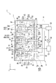
- FIG. 1 is a cross-sectional view showing an engine including a cylinder head according to an embodiment of the present invention. It is the top view which looked at the engine of FIG. 1 from upper direction.
- FIG. 3 is a cross-sectional view taken along the line III-III in FIG.
- FIG. 4 is a cross-sectional view taken along line IV-IV of FIG.
- FIG. 5 is a cross-sectional view taken along the line V-V of FIG. 3;
- a cylinder head 3 constitutes an engine 1 together with a cylinder block 2.
- the engine 1 of the present embodiment is a diesel engine. 1 to 5, the direction in which the cylinder block 2 and the cylinder head 3 are arranged is taken as the Z-axis direction. Further, a first orthogonal direction orthogonal to the Z-axis direction is taken as a Y-axis direction. Furthermore, a second orthogonal direction orthogonal to the Z-axis direction and the Y-axis direction is taken as an X-axis direction.
- cylinders 11 are formed in the cylinder block 2.
- the cylinder 11 is a space in which the piston 4 is disposed.
- the cylinder 11 opens at the top surface 2 a of the cylinder block 2.
- the piston 4 reciprocates in the vertical direction (Z-axis direction) in response to the pressure of the combustion gas burned in the cylinder 11.
- the cylinder block 2 of the present embodiment has a plurality of (three in the illustrated example) cylinders 11 as shown in FIG.
- the plurality of cylinders 11 are arranged in a line in a first orthogonal direction (Y-axis direction) orthogonal to the vertical direction.
- the first orthogonal direction in which the plurality of cylinders 11 are arranged is referred to as a cylinder row direction.
- a camshaft 5 for driving a rocker arm 52 described later is disposed in the cylinder block 2.
- the camshaft 5 extends in the cylinder row direction.
- the camshaft 5 rotates in response to the reciprocating motion of the piston 4.
- the cylinder head 3 is disposed to overlap the upper surface 2 a of the cylinder block 2.
- the cylinder head 3 includes a cylinder head body 6 and a rocker housing 7.
- the cylinder head 3 further includes an intake manifold 8.
- the cylinder head body 6 has an intake port 21 and an exhaust port 22.
- the intake port 21 and the exhaust port 22 communicate with the cylinders 11 of the cylinder block 2 respectively.
- the first end in the longitudinal direction of the intake port 21 opens to the lower surface 6 b of the cylinder head main body 6 facing the upper surface 2 a of the cylinder block 2.
- the first end of the intake port 21 is connected to the cylinder 11.
- the second end of the intake port 21 opens in the side portion of the cylinder head body 6 that faces the vertical direction and one side (X-axis positive direction side) in the second orthogonal direction orthogonal to the cylinder row direction.
- the second end of the intake port 21 is connected to an intake manifold 8 described later.
- the intake port 21 extends upward from the cylinder 11 side, and then is bent and extends to one side in the second orthogonal direction. That is, the intake port 21 is formed to intake air from the intake side of the cylinder head main body 6 which is one side in the second orthogonal direction.
- the first end in the longitudinal direction of the exhaust port 22 opens to the lower surface 6 b of the cylinder head main body 6 similarly to the intake port 21.
- the first end of the exhaust port 22 is connected to the cylinder 11.
- the second end of the exhaust port 22 opens at the side of the cylinder head body 6 facing the other side (X-axis negative direction side) in the second orthogonal direction.
- the exhaust port 22 extends upward from the cylinder 11 side, and then bends and extends to the other side in the second orthogonal direction. That is, the exhaust port 22 is formed to exhaust to the exhaust side of the cylinder head main body 6 which is the other side in the second orthogonal direction.
- the intake port 21 and the exhaust port 22 are provided at positions close to the lower end side (the cylinder block 2 side) of the cylinder head main body 6.
- the intake port 21 and the exhaust port 22 communicate with each of the plurality of cylinders 11. That is, the intake port 21 and the exhaust port 22 are formed to correspond to the respective cylinders 11. In the present embodiment, as shown in FIG. 2, two intake ports 21 and one exhaust port 22 are formed for one cylinder 11. The plurality of intake ports 21 and the plurality of exhaust ports 22 are arranged in the cylinder row direction.
- the cylinder head main body 6 is provided with an intake valve 23 for opening and closing the first end of each intake port 21 so as to be movable in the vertical direction. A portion of the intake valve 23 protrudes from the upper surface 6 a of the cylinder head body 6. Similar to the intake valve 23, the cylinder head main body 6 is provided with an exhaust valve 24 that opens and closes the first end of each exhaust port 22. The configuration and arrangement of the exhaust valve 24 are similar to those of the intake valve 23.
- the cylinder head body 6 is provided with a fuel injector 25 (injector) for injecting fuel into the cylinder 11.
- the fuel injector 25 penetrates the cylinder head body 6 in the vertical direction.
- One fuel injector 25 is provided for each of the plurality of cylinders 11. That is, in the present embodiment, the plurality of fuel injectors 25 are arranged in the cylinder row direction.
- Each fuel injector 25 is positioned to correspond to the center of each cylinder 11 in a plan view (FIG. 2) when the cylinder head body 6 is viewed from the upper side.
- Around the fuel injector 25 are located the first end of the intake port 21 and the exhaust port 22 opening to the same cylinder 11, and the intake valve 23 and the exhaust valve 24 for opening and closing these.
- a fuel supply pipe 26 extending to one side (intake side) in the second orthogonal direction is connected to an upper end portion of each fuel injector 25 projecting from the upper surface 6 a of the cylinder head main body 6.
- Each fuel supply pipe 26 penetrates an intake side wall 41A of the rocker housing 7 described later.
- the plurality of fuel supply pipes 26 are connected to the common rail 29.
- the common rail 29 is a pipe portion that holds the fuel at a predetermined pressure (high pressure).
- the common rail 29 may be fixed to, for example, the cylinder head 3.
- the fuel flows from the fuel tank 27 to the fuel pump 28 and the common rail 29 in order, and then flows through the fuel supply pipes 26 and the fuel injectors 25 in order to be injected to the cylinders 11.
- the rocker housing 7 is integrally formed on the cylinder head body 6.
- the inside of the locker housing 7 is a valve system accommodation space 40.
- the rocker housing 7 has a side wall 41 and an end wall 42.
- the side wall 41 and the end wall 42 respectively extend above the cylinder head body 6 (in the positive Z-axis direction) at the periphery of the upper surface 6 a of the cylinder head body 6.
- the side wall 41 extends in the cylinder row direction (Y-axis direction) at both ends of the cylinder head main body 6 in the second orthogonal direction (X-axis direction).
- the end wall 42 extends in the second orthogonal direction at both ends of the cylinder head body 6 in the cylinder row direction.
- a space surrounded by the pair of side walls 41 and the pair of end walls 42 is the above-described valve system accommodation space 40.
- the bottom surface of the valve system accommodation space 40 is formed by the upper surface 6 a of the cylinder head body 6.
- the valve shaft accommodation space 40 accommodates a rocker shaft 51 and a rocker arm 52 for driving the intake valve 23 and the exhaust valve 24 described above as a valve system component.
- the rocker shaft 51 is integrally formed with a rocker bracket 53 fixed to the bottom of the valve system accommodation space 40.
- the rocker shaft 51 is spaced apart above the bottom surface of the valve system accommodation space 40 by the rocker bracket 53.
- the rocker shaft 51 extends in the cylinder row direction.
- the rocker shaft 51 and the rocker bracket 53 are disposed in the region of the valve valve housing space 40 on the exhaust side (X-axis negative direction side) of the cylinder head body 6.
- the rocker arm 52 is pivotably attached to the rocker shaft 51.
- the rocker arm 52 is provided for each of the intake valve 23 and the exhaust valve 24 corresponding to each cylinder 11.
- the plurality of rocker arms 52 are arranged in the cylinder row direction.
- Each rocker arm 52 pivots about the rocker shaft 51 by the push rod 54 (FIG. 1) penetrating in the vertical direction of the cylinder head body 6 moving in the vertical direction with the rotation of the camshaft 5 described above. Do. Thereby, the intake valve 23 and the exhaust valve 24 can be driven.
- the rocker shaft 51 is divided into a plurality of parts.
- the plurality of rocker shafts 51 are arranged at intervals in the cylinder row direction.
- the rocker shaft 51 is provided to correspond to each cylinder 11. That is, the number of rocker shafts 51 is the same as the number of cylinders 11.
- a rocker arm 52 corresponding to each cylinder 11 is attached to the same rocker shaft 51.
- the rocker brackets 53 are provided for the plurality of rocker shafts 51, respectively.
- Each side wall 41 of the rocker housing 7 has a side wall body 44 and a proximal end 45.
- the base end 45 of each side wall 41 extends along the lower end of the side wall main body 44 in the cylinder row direction, and is a portion connecting the side wall main body 44 to the cylinder head main body 6.
- the thickness of the proximal end 45 of each side wall 41 is thicker than the thickness of the side wall main body 44.
- a flow passage 46 extending in the extension direction (Y-axis direction) of the proximal end 45 is formed in the proximal end 45 is formed. That is, the flow path 46 extends in the cylinder row direction.
- ⁇ Fuel return channel> As shown in FIGS. 1 to 4, in the base end portion 45 of the intake side sidewall 41A disposed on the intake side (the positive direction side in the X-axis) of the pair of side walls 41, the aforementioned flow passage As 46, a fuel return passage 46A is formed. The fuel (fluid) returned from the plurality of fuel injectors 25 flows through the fuel return passage 46A. As shown in FIGS. 2 to 4, connection paths 47 respectively extending from the plurality of fuel injectors 25 inside the cylinder head main body 6 are connected to the fuel return flow path 46A.
- connection flow paths 47 are connected to fuel return ports (not shown) formed at mid-longitudinal portions of the fuel injectors 25.
- the second end of each connection channel 47 is connected to the fuel return channel 46A.
- the fuel return port is located below the fuel return passage 46A (in the negative Z-axis direction).
- each connection flow path 47 inclines and extends upward as it goes from the fuel injector 25 to the intake side of the cylinder head body 6.
- the plurality of connection channels 47 are arranged at intervals in the longitudinal direction of the fuel return channel 46A.
- a first end of the fuel return passage 46A in the longitudinal direction (Y-axis direction) is connected to the fuel tank 27.
- the second end of the fuel return passage 46A is connected to the common rail 29. Further, a valve (not shown) is provided between the common rail 29 and the fuel return flow path 46A for opening and closing a pipe line connecting them. The valve opens when the pressure in the common rail 29 becomes excessively high and when the engine 1 stops. As a result, the fuel in the common rail 29 flows out to the fuel return passage 46A, so the pressure in the common rail 29 can be reduced. The fuel that has flowed out of the common rail 29 into the fuel return passage 46A returns to the fuel tank 27 as described above.
- ⁇ Lubricating oil flow path> As shown in FIGS. 1 to 3, in the base end portion 45 of the exhaust side sidewall 41B disposed on the exhaust side (X-axis negative direction side) of the cylinder head main body 6 among the pair of side walls 41, As the flow passage 46, a lubricating oil flow passage 46B is formed.
- the lubricating oil flow path 46B is connected to a supply flow path 48 (indicated by a broken line in FIGS.
- a plurality of supply channels 48 are connected to the lubricating oil channel 46B.
- the plurality of supply channels 48 are arranged at intervals in the longitudinal direction of the lubricating oil channel 46B.
- Each supply flow passage 48 extends toward the intake side (X-axis positive direction side) of the cylinder head main body 6 inside the cylinder head main body 6 so as to go from the lubricating oil flow passage 46B to the rocker bracket 53, From the cylinder head body 6, it is bent upward and extends into the rocker bracket 53. Furthermore, each supply flow passage 48 passes through the inside of the rocker bracket 53 and the rocker shaft 51, and opens on the outer peripheral surface of the rocker shaft 51 on which the rocker arm 52 slides. As a result, as shown in FIG. 3, lubricating oil can be supplied to the sliding portion between the rocker shaft 51 and the rocker arm 52.
- the supply path of the lubricating oil to the lubricating oil flow path 46B may be arbitrary. The lubricating oil may be supplied from, for example, the cylinder block 2 side to the lubricating oil flow path 46B.
- the intake manifold 8 is integrally formed on the intake side (X-axis positive direction side) of the cylinder head main body 6.
- the intake manifold 8 extends in the cylinder row direction so as to be connected to each intake port 21.
- the connection flow path 47 connecting the fuel return flow path 46A and the fuel injector 25 is a valve system accommodation space 40, an intake port 21, and the like in the cylinder head main body 6. It extends obliquely from the fuel injector 25 toward the intake side so as to pass between the internal space of the intake manifold 8 communicating with the intake port 21 and the internal space.
- the cylinder head 3 of the present embodiment configured as described above is fixed to the cylinder block 2 by a fixing bolt (not shown).
- the cylinder head main body 6 is formed with a plurality of bolt holes 60 which are penetrated in the vertical direction and through which fixing bolts are inserted.
- Each bolt hole 60 opens in a region of the upper surface 6 a of the cylinder head body 6 surrounded by the rocker housing 7.
- Each bolt hole 60 is formed at a position corresponding to the periphery of each cylinder 11.
- four bolt holes 60 are arranged in the circumferential direction of each cylinder 11. Some of the bolt holes 60 are located in the region between the two adjacent rocker shafts 51 on the upper surface 6 a of the cylinder head body 6.
- the thickness of the base end 45 of the side wall 41 of the rocker housing 7 is thicker than the side wall main body 44. Therefore, even if the thickness of the side wall main body 44 is thin, the rigidity of the side wall 41 of the rocker housing 7 can be improved. Further, since the side wall main body 44 can be formed thin, weight reduction of the cylinder head 3 can also be achieved. Hereinafter, this point will be described.
- the side wall 41 of the rocker housing 7 is simply formed integrally with the cylinder head body 6, stress is likely to be concentrated on the proximal end 45 of the side wall 41. Therefore, when the entire side wall 41 is thin, the base end portion 45 of the side wall 41 is easily broken. On the other hand, when the entire side wall 41 is formed thick, stress concentration on the proximal end 45 of the side wall 41 can be suppressed, but the weight of the entire cylinder head 3 becomes heavy. On the other hand, in the cylinder head 3 of the present embodiment, the base end 45 of the side wall 41 is formed thicker than the side wall main body 44. For this reason, while being able to suppress the stress concentration to the base end part 45 of the side wall 41, reduction of the weight of the cylinder head 3 whole can be aimed at.
- the flow path 46 through which the fuel and the lubricating oil flow is formed in the base end portion 45 of the side wall 41 having a large thickness. Therefore, the cylinder head main body 6 can be miniaturized as compared with the case where the flow path 46 is formed in another part (for example, the inside of the cylinder head main body 6). Further, as described above, the thickness of the side wall main body 44 can be reduced, so that the rocker housing 7 can be miniaturized. Therefore, the cylinder head 3 can be miniaturized.
- the side wall 41 of the rocker housing 7 and the fuel return passage 46A and the lubricating oil passage 46B formed in the base end 45 of the side wall 41 It extends in the cylinder row direction. That is, by forming the base end 45 of the side wall 41 of the rocker housing 7 longer than the end wall 42 of the rocker housing 7 thick, the rigidity of the side wall 41 extending in the cylinder row direction can be improved. Furthermore, by arranging the plurality of fuel injectors 25 in the cylinder row direction (the extension direction of the fuel return flow path 46A), the distances from the fuel return flow path 46A to the respective fuel injectors 25 can be made uniform. .
- connection channels 47 connecting the fuel return channel 46A and the plurality of fuel injectors 25 is not long, and all the connection channels 47 can be formed short.
- the distances from the lubricating oil channel 46B to the respective valve system components can be equalized. it can.
- a part of the plurality of supply channels 48 extending from the lubricating oil channel 46B to the plurality of valve system components is not long, and all the supply channels 48 can be formed short.
- the connecting flow path 47 connecting the fuel return flow path 46A and the fuel injector 25 communicates with the intake port 21 and the intake port 21. It extends obliquely upward from the fuel injector 25 toward the intake side so as to pass between the interior space of Therefore, the opening of the intake port 21 located below the connection flow path 47 and serving as a connection portion with the intake manifold 8 can be enlarged.
- Reference numeral 21S in FIG. 3 indicates the size of the opening of the intake port 21. Thereby, the intake resistance in the engine 1 can be reduced, and the fuel efficiency of the engine 1 can be improved.
- the intake manifold 8 is integrally formed with the cylinder head main body 6.
- the connection flow path 47 can be formed near the boundary region between the inside of the cylinder head body 6 and the intake manifold 8. Further, even if the connection flow channel 47 is formed over the inside of the cylinder head main body 6 and the inside of the intake manifold 8, fuel can flow smoothly in the connection flow channel 47.
- connection flow path 47 is formed over the inside of the cylinder head body 6 and the inside of the intake manifold 8.
- the connection becomes a flow resistance in the connection flow path 47. Therefore, it is difficult to flow the fuel smoothly in the connection flow path 47.
- the rocker shaft 51 is divided into a plurality of parts. Therefore, even if the bolt hole 60 is formed in the region between two adjacent rocker shafts 51 in the upper surface 6 a of the cylinder head main body 6, the bolt holes 60 and the fixing bolts inserted therein are made by the rocker shaft 51. It can be prevented from being covered.
- the cylinder head 3 can be attached to and detached from the cylinder block 2 while the rocker shaft 51 is attached to the cylinder head 3. That is, the cylinder head 3 can be easily attached to and detached from the cylinder block 2.
- the number of rocker shafts may be one, for example. That is, all rocker arms may be attached to the same rocker shaft.
- the fluid flowing through the flow path may be, for example, cooling water for cooling the cylinder head body.
- the flow path through which the cooling water flows may be, for example, a flow path that leads the cooling water from the cooling water flow space formed inside the cylinder head main body to the accessory (for example, a hydraulic pump).
- the cooling water led to the accessory may, for example, cool the accessory.
- the number of cylinders in the engine of the present invention may be one, for example.
- the engine of the present invention may be applied to any work vehicle such as a dump truck, a hydraulic shovel, a bulldozer, and an engine-type forklift.
Landscapes
- Engineering & Computer Science (AREA)
- Mechanical Engineering (AREA)
- General Engineering & Computer Science (AREA)
- Chemical & Material Sciences (AREA)
- Combustion & Propulsion (AREA)
- Cylinder Crankcases Of Internal Combustion Engines (AREA)
- Fuel-Injection Apparatus (AREA)
- Lubrication Of Internal Combustion Engines (AREA)
Abstract
Culasse (3) comprenant : un corps de culasse (6) comprenant un orifice d'admission (21) qui est en communication avec un cylindre (11) d'un bloc-cylindres (2), et un orifice de décharge (22) qui est en communication avec ledit cylindre ; et un boîtier de culbuteur (7) moulé d'un seul tenant sur le corps de culasse, le côté interne du boîtier de culbuteur servant d'espace de logement de système de soupape (40). Le boîtier de culbuteur comprend : une paroi latérale (41) comprenant un corps de paroi latérale (44), et une partie d'extrémité de base (45) qui s'étend le long de l'extrémité inférieure du corps de paroi latérale, relie le corps de paroi latérale au corps de culasse, et est plus épais que le corps de paroi latérale. Un passage d'écoulement (46) à travers lequel s'écoule un fluide est formé à l'intérieur de la partie d'extrémité de base, et s'étend dans la direction d'extension de la partie d'extrémité de base.
Priority Applications (5)
| Application Number | Priority Date | Filing Date | Title |
|---|---|---|---|
| DE112018000078.8T DE112018000078B4 (de) | 2018-10-29 | 2018-10-29 | Zylinderkopf mit Kraftstoffrückführungs-Strömungsweg |
| US16/318,866 US10968861B2 (en) | 2018-10-29 | 2018-10-29 | Cylinder head |
| PCT/JP2018/040111 WO2019066089A1 (fr) | 2018-10-29 | 2018-10-29 | Culasse |
| JP2018562145A JP6751449B2 (ja) | 2018-10-29 | 2018-10-29 | シリンダヘッド |
| CN201880003051.6A CN109996947B (zh) | 2018-10-29 | 2018-10-29 | 气缸盖 |
Applications Claiming Priority (1)
| Application Number | Priority Date | Filing Date | Title |
|---|---|---|---|
| PCT/JP2018/040111 WO2019066089A1 (fr) | 2018-10-29 | 2018-10-29 | Culasse |
Publications (1)
| Publication Number | Publication Date |
|---|---|
| WO2019066089A1 true WO2019066089A1 (fr) | 2019-04-04 |
Family
ID=65901495
Family Applications (1)
| Application Number | Title | Priority Date | Filing Date |
|---|---|---|---|
| PCT/JP2018/040111 Ceased WO2019066089A1 (fr) | 2018-10-29 | 2018-10-29 | Culasse |
Country Status (5)
| Country | Link |
|---|---|
| US (1) | US10968861B2 (fr) |
| JP (1) | JP6751449B2 (fr) |
| CN (1) | CN109996947B (fr) |
| DE (1) | DE112018000078B4 (fr) |
| WO (1) | WO2019066089A1 (fr) |
Families Citing this family (2)
| Publication number | Priority date | Publication date | Assignee | Title |
|---|---|---|---|---|
| US11242819B2 (en) | 2020-02-17 | 2022-02-08 | Komatsu Ltd. | Cylinder head and engine |
| GB2601191B (en) * | 2020-11-24 | 2023-02-15 | Caterpillar Shrewsbury Ltd | A rocker housing for an internal combustion engine |
Citations (4)
| Publication number | Priority date | Publication date | Assignee | Title |
|---|---|---|---|---|
| JPH046564U (fr) * | 1990-04-26 | 1992-01-21 | ||
| JPH0771311A (ja) * | 1993-08-31 | 1995-03-14 | Suzuki Motor Corp | シリンダヘッド構造 |
| JPH11280596A (ja) * | 1998-03-27 | 1999-10-12 | Nissan Diesel Motor Co Ltd | 内燃機関の燃料配管装置 |
| JP2016217244A (ja) * | 2015-05-20 | 2016-12-22 | トヨタ自動車株式会社 | 内燃機関 |
Family Cites Families (21)
| Publication number | Priority date | Publication date | Assignee | Title |
|---|---|---|---|---|
| US3174467A (en) * | 1962-04-23 | 1965-03-23 | Kaiser Jeep Corp | Diesel cylinder head |
| US4522169A (en) * | 1982-09-29 | 1985-06-11 | Aisin Seiki Kabushiki Kaisha | Variable cylinder device for internal combustion engines |
| JPS59201910A (ja) * | 1983-04-28 | 1984-11-15 | Mazda Motor Corp | エンジンの弁不作動装置 |
| JP3182948B2 (ja) | 1992-11-30 | 2001-07-03 | スズキ株式会社 | エンジンの吸気装置 |
| JP3760417B2 (ja) * | 1993-12-27 | 2006-03-29 | 本田技研工業株式会社 | ディーゼルエンジンの燃料噴射装置 |
| DE4440718A1 (de) * | 1994-11-15 | 1996-01-04 | Daimler Benz Ag | Ventilantriebssystem für eine mehrzylindrige Brennkraftmaschine |
| JPH09250321A (ja) | 1996-03-15 | 1997-09-22 | Kubota Corp | エンジンの動弁装置 |
| AT410009B (de) | 1997-04-09 | 2003-01-27 | Avl List Gmbh | Mehrzylinder-viertakt-brennkraftmaschine |
| TW358848B (en) | 1997-06-25 | 1999-05-21 | Mitsubishi Heavy Ind Ltd | Structure of overhead-valve internal combustion engine and manufacturing method for the same |
| US6098595A (en) * | 1998-08-17 | 2000-08-08 | Cummins Engine Company, Inc. | Intake port injection system with shared injectors |
| JP2000282990A (ja) * | 1999-03-31 | 2000-10-10 | Komatsu Ltd | ディーゼルエンジンの燃料配管構造 |
| DE10226688B4 (de) | 2002-06-15 | 2004-12-09 | Daimlerchrysler Ag | Zylinderkopf einer Hubkolbenbrennkraftmaschine |
| US6998334B2 (en) * | 2002-07-08 | 2006-02-14 | Micron Technology, Inc. | Semiconductor devices with permanent polymer stencil and method for manufacturing the same |
| CN2665370Y (zh) * | 2003-12-18 | 2004-12-22 | 天津朝霞摩托车技术开发有限公司 | 气缸头采用机油冷却的小型汽油机 |
| JP4540655B2 (ja) * | 2006-11-24 | 2010-09-08 | 本田技研工業株式会社 | デコンプ装置を備える内燃機関 |
| US7895992B2 (en) * | 2007-09-24 | 2011-03-01 | Ford Global Technologies, Llc | Push rod engine with inboard exhaust |
| JP5139112B2 (ja) * | 2008-02-19 | 2013-02-06 | ヤマハ発動機株式会社 | エンジン |
| JP5351588B2 (ja) * | 2009-03-31 | 2013-11-27 | 本田技研工業株式会社 | 内燃機関の吸気通路構造 |
| JP5662965B2 (ja) * | 2012-06-06 | 2015-02-04 | 大豊工業株式会社 | エンジンの潤滑油供給機構 |
| CN203441616U (zh) * | 2013-07-30 | 2014-02-19 | 中国重汽集团济南动力有限公司 | 一种整体式气缸盖 |
| US20170335791A1 (en) | 2016-05-23 | 2017-11-23 | Caterpillar Inc. | Cylinder Head |
-
2018
- 2018-10-29 WO PCT/JP2018/040111 patent/WO2019066089A1/fr not_active Ceased
- 2018-10-29 DE DE112018000078.8T patent/DE112018000078B4/de active Active
- 2018-10-29 US US16/318,866 patent/US10968861B2/en active Active
- 2018-10-29 JP JP2018562145A patent/JP6751449B2/ja active Active
- 2018-10-29 CN CN201880003051.6A patent/CN109996947B/zh active Active
Patent Citations (4)
| Publication number | Priority date | Publication date | Assignee | Title |
|---|---|---|---|---|
| JPH046564U (fr) * | 1990-04-26 | 1992-01-21 | ||
| JPH0771311A (ja) * | 1993-08-31 | 1995-03-14 | Suzuki Motor Corp | シリンダヘッド構造 |
| JPH11280596A (ja) * | 1998-03-27 | 1999-10-12 | Nissan Diesel Motor Co Ltd | 内燃機関の燃料配管装置 |
| JP2016217244A (ja) * | 2015-05-20 | 2016-12-22 | トヨタ自動車株式会社 | 内燃機関 |
Also Published As
| Publication number | Publication date |
|---|---|
| CN109996947A (zh) | 2019-07-09 |
| CN109996947B (zh) | 2021-01-29 |
| JP6751449B2 (ja) | 2020-09-02 |
| US20200132015A1 (en) | 2020-04-30 |
| DE112018000078B4 (de) | 2023-03-23 |
| JPWO2019066089A1 (ja) | 2019-11-14 |
| DE112018000078T5 (de) | 2019-08-08 |
| US10968861B2 (en) | 2021-04-06 |
Similar Documents
| Publication | Publication Date | Title |
|---|---|---|
| CN103328798B (zh) | 具有集成气门系的气缸盖罩模块 | |
| US7484479B2 (en) | Water-cooled internal combustion engine | |
| US8474417B2 (en) | Lubricating system for air-cooled general-purpose engine | |
| JP6476796B2 (ja) | 多気筒エンジンの冷却用オイル通路構造 | |
| CN107489477B (zh) | 内燃机 | |
| WO2019066089A1 (fr) | Culasse | |
| US7938094B2 (en) | Internal combustion engine | |
| JP2014152758A (ja) | オイルシャワーパイプ | |
| JP2017125467A (ja) | 内燃機関の冷却構造 | |
| JP5307061B2 (ja) | 内燃機関のオイル劣化防止装置 | |
| EP0682176A1 (fr) | Moteur à combustion interne | |
| CN109026322B (zh) | 发动机的冷却用油通路构造 | |
| EP3015355A1 (fr) | Moteur et motocyclette comportant celui-ci | |
| KR102712889B1 (ko) | 실린더 라이너 및 선박용 내연기관 | |
| CN109415958B (zh) | 发动机装置 | |
| US10634020B2 (en) | Internal combustion engine | |
| US20170184051A1 (en) | Cylinder head cooling structure | |
| JPH09151783A (ja) | 多気筒エンジン | |
| US6782864B2 (en) | Mount structure for an engine accessory | |
| JP4605607B2 (ja) | 水冷式エンジンの冷却水通路構造 | |
| JP2007064054A (ja) | 二サイクル式多気筒内燃機関 | |
| JP2016217271A (ja) | 内燃機関 | |
| JP2004308519A (ja) | 多気筒エンジン | |
| JPH06159196A (ja) | 内燃機関の燃料配管の配置 | |
| JP2013155658A (ja) | 内燃機関の油路構造 |
Legal Events
| Date | Code | Title | Description |
|---|---|---|---|
| ENP | Entry into the national phase |
Ref document number: 2018562145 Country of ref document: JP Kind code of ref document: A |
|
| 121 | Ep: the epo has been informed by wipo that ep was designated in this application |
Ref document number: 18861896 Country of ref document: EP Kind code of ref document: A1 |
|
| 122 | Ep: pct application non-entry in european phase |
Ref document number: 18861896 Country of ref document: EP Kind code of ref document: A1 |