WO2019069517A1 - 案内装置、円盤状部材移動装置、缶蓋製造システム、および、飲料缶製造システム - Google Patents
案内装置、円盤状部材移動装置、缶蓋製造システム、および、飲料缶製造システム Download PDFInfo
- Publication number
- WO2019069517A1 WO2019069517A1 PCT/JP2018/025067 JP2018025067W WO2019069517A1 WO 2019069517 A1 WO2019069517 A1 WO 2019069517A1 JP 2018025067 W JP2018025067 W JP 2018025067W WO 2019069517 A1 WO2019069517 A1 WO 2019069517A1
- Authority
- WO
- WIPO (PCT)
- Prior art keywords
- guiding
- downstream
- upstream
- guide
- members
- Prior art date
- Legal status (The legal status is an assumption and is not a legal conclusion. Google has not performed a legal analysis and makes no representation as to the accuracy of the status listed.)
- Ceased
Links
Images





Classifications
-
- B—PERFORMING OPERATIONS; TRANSPORTING
- B21—MECHANICAL METAL-WORKING WITHOUT ESSENTIALLY REMOVING MATERIAL; PUNCHING METAL
- B21D—WORKING OR PROCESSING OF SHEET METAL OR METAL TUBES, RODS OR PROFILES WITHOUT ESSENTIALLY REMOVING MATERIAL; PUNCHING METAL
- B21D51/00—Making hollow objects
- B21D51/16—Making hollow objects characterised by the use of the objects
- B21D51/26—Making hollow objects characterised by the use of the objects cans or tins; Closing same in a permanent manner
- B21D51/2692—Manipulating, e.g. feeding and positioning devices; Control systems
-
- B—PERFORMING OPERATIONS; TRANSPORTING
- B21—MECHANICAL METAL-WORKING WITHOUT ESSENTIALLY REMOVING MATERIAL; PUNCHING METAL
- B21D—WORKING OR PROCESSING OF SHEET METAL OR METAL TUBES, RODS OR PROFILES WITHOUT ESSENTIALLY REMOVING MATERIAL; PUNCHING METAL
- B21D51/00—Making hollow objects
- B21D51/16—Making hollow objects characterised by the use of the objects
- B21D51/26—Making hollow objects characterised by the use of the objects cans or tins; Closing same in a permanent manner
- B21D51/2653—Methods or machines for closing cans by applying caps or bottoms
-
- B—PERFORMING OPERATIONS; TRANSPORTING
- B21—MECHANICAL METAL-WORKING WITHOUT ESSENTIALLY REMOVING MATERIAL; PUNCHING METAL
- B21D—WORKING OR PROCESSING OF SHEET METAL OR METAL TUBES, RODS OR PROFILES WITHOUT ESSENTIALLY REMOVING MATERIAL; PUNCHING METAL
- B21D51/00—Making hollow objects
- B21D51/16—Making hollow objects characterised by the use of the objects
- B21D51/38—Making inlet or outlet arrangements of cans, tins, baths, bottles, or other vessels; Making can ends; Making closures
- B21D51/44—Making closures, e.g. caps
- B21D51/446—Feeding or removal of material
-
- B—PERFORMING OPERATIONS; TRANSPORTING
- B65—CONVEYING; PACKING; STORING; HANDLING THIN OR FILAMENTARY MATERIAL
- B65G—TRANSPORT OR STORAGE DEVICES, e.g. CONVEYORS FOR LOADING OR TIPPING, SHOP CONVEYOR SYSTEMS OR PNEUMATIC TUBE CONVEYORS
- B65G21/00—Supporting or protective framework or housings for endless load-carriers or traction elements of belt or chain conveyors
- B65G21/20—Means incorporated in, or attached to, framework or housings for guiding load-carriers, traction elements or loads supported on moving surfaces
-
- B—PERFORMING OPERATIONS; TRANSPORTING
- B65—CONVEYING; PACKING; STORING; HANDLING THIN OR FILAMENTARY MATERIAL
- B65G—TRANSPORT OR STORAGE DEVICES, e.g. CONVEYORS FOR LOADING OR TIPPING, SHOP CONVEYOR SYSTEMS OR PNEUMATIC TUBE CONVEYORS
- B65G21/00—Supporting or protective framework or housings for endless load-carriers or traction elements of belt or chain conveyors
- B65G21/20—Means incorporated in, or attached to, framework or housings for guiding load-carriers, traction elements or loads supported on moving surfaces
- B65G21/2045—Mechanical means for guiding or retaining the load on the load-carrying surface
- B65G21/2054—Mechanical means for guiding or retaining the load on the load-carrying surface comprising elements movable in the direction of load-transport
-
- B—PERFORMING OPERATIONS; TRANSPORTING
- B65—CONVEYING; PACKING; STORING; HANDLING THIN OR FILAMENTARY MATERIAL
- B65G—TRANSPORT OR STORAGE DEVICES, e.g. CONVEYORS FOR LOADING OR TIPPING, SHOP CONVEYOR SYSTEMS OR PNEUMATIC TUBE CONVEYORS
- B65G21/00—Supporting or protective framework or housings for endless load-carriers or traction elements of belt or chain conveyors
- B65G21/20—Means incorporated in, or attached to, framework or housings for guiding load-carriers, traction elements or loads supported on moving surfaces
- B65G21/2045—Mechanical means for guiding or retaining the load on the load-carrying surface
- B65G21/2063—Mechanical means for guiding or retaining the load on the load-carrying surface comprising elements not movable in the direction of load-transport
- B65G21/2072—Laterial guidance means
-
- B—PERFORMING OPERATIONS; TRANSPORTING
- B65—CONVEYING; PACKING; STORING; HANDLING THIN OR FILAMENTARY MATERIAL
- B65G—TRANSPORT OR STORAGE DEVICES, e.g. CONVEYORS FOR LOADING OR TIPPING, SHOP CONVEYOR SYSTEMS OR PNEUMATIC TUBE CONVEYORS
- B65G11/00—Chutes
- B65G11/14—Chutes extensible, e.g. telescopic
- B65G11/143—Chutes extensible, e.g. telescopic for articles
-
- B—PERFORMING OPERATIONS; TRANSPORTING
- B67—OPENING, CLOSING OR CLEANING BOTTLES, JARS OR SIMILAR CONTAINERS; LIQUID HANDLING
- B67B—APPLYING CLOSURE MEMBERS TO BOTTLES JARS, OR SIMILAR CONTAINERS; OPENING CLOSED CONTAINERS
- B67B3/00—Closing bottles, jars or similar containers by applying caps
- B67B3/02—Closing bottles, jars or similar containers by applying caps by applying flanged caps, e.g. crown caps, and securing by deformation of flanges
- B67B3/06—Feeding caps to capping heads
Definitions
- the present invention relates to a guiding device, a disc-like member moving device, a can lid manufacturing system, and a beverage can manufacturing system.
- the supply includes an annular flange portion and a guide member provided between two flange portions, and a central portion surrounded by the flange portion and the guide member forms a passage of the can lid.
- An alignment arrangement is disclosed.
- a guiding device for guiding a disc-like member used as a can lid a plurality of guiding members are arranged side by side along the conveying direction of the disc-like member, and a part of the guiding members is located upstream in the conveying direction of the disc
- the overall length of the guiding device can be changed by moving it to the side or the downstream side.
- this one part guide member interferes with the other guide member located coaxially with this one part guide member.
- the strength of the guide device may be reduced due to the hollow guide member or the like.
- An object of the present invention is to make it possible to change the overall length of a guiding device for guiding a disc-like member used for a can lid while suppressing a reduction in strength.
- the guiding device to which the present invention is applied is a disc-like member used as a can lid, and is disposed and transported along the transport path of the disc-like member transported in the thickness direction.
- a plurality of upstream guiding members arranged so as to be different in circumferential position from each other, the upstream guiding portion for guiding the disc-like member and the circumferential position of the transported disc-like member being different from each other
- a downstream guide portion for guiding the disc-like member guided and conveyed by the upstream guide member, the upstream guide in the circumferential direction.
- each of the side guide members is different from the position of each of the downstream side guide members in the circumferential direction, and at least one of the upstream side guide portion and the downstream side guide portion is opposed to the other It is configured guide device so that it can advance and retreat.
- a portion where both the upstream guide portion and the downstream guide portion are located exists beside the transfer path of the disc-like member, and the upstream portion guides the disc-like member. It can be characterized in that the guide of the discoid member by the downstream guide part is started during the process.
- the plurality of upstream guiding members and the plurality of downstreams are planes that are orthogonal to the transport direction of the disk-shaped member and pass through both the upstream guiding portion and the downstream guiding portion.
- the side guides may be characterized in that they rest on the same circle. Further, in the circumferential direction of the same circle, the upstream guide member and the downstream guide member may be alternately arranged. Further, the end portion of the plurality of upstream guide members and the end portion located on the upstream side in the conveyance direction of the disk-like member, and the end portion of the plurality of downstream guide members, the conveyance of the disk-like member A fixed member fixed to a fixed place is attached to at least one end of the end located on the downstream side of the direction, and a through hole for passing a fastening member is formed in the fixed member. The through hole may be formed in an elongated hole shape.
- the guiding device to which the present invention is applied includes a plurality of upstream guiding members disposed along the conveyance path of the disc-like member used as a can lid, and the guidance of the disc-like member And a downstream guiding unit for guiding the disc-like member guided and conveyed by the upstream guiding member.
- the upstream guiding portion is a guiding area for guiding the disc-like member, and the guiding area in the conveying direction of the disc-like member and the guiding area for the downstream guiding part to guide the disc-like member
- the guide region in the transport direction partially overlaps in the transport direction, and at least one of the upstream guide portion and the downstream guide portion is moved relative to the other guide portion.
- a plurality of portions in the longitudinal direction of each of the plurality of downstream guide members constituting the downstream guide portion are configured such that the length in the transport direction of the portion where the It is a guide device which is fixed to the upstream side guide part, and a plurality of places in a longitudinal direction of each of a plurality of upstream side guide members which constitute the upstream side guide part are fixed to the downstream side guide part.
- the upstream guide member is fixed to a portion positioned on the downstream side in the transport direction among the plurality of upstream guide members, and the plurality of upstream guide members are connected and fixed to the downstream guide member
- the fixing member is fixed to a portion of the plurality of downstream guide members located on the upstream side in the transport direction, and the plurality of downstream guide members are connected and fixed to the upstream guide member.
- the upstream side guide member is fixed to the downstream side guide member via the first fixing member and the second fixing member, the upstream side A plurality of locations in the longitudinal direction of the guide member are fixed to the downstream guide portion, and the downstream guide member is fixed to the upstream guide member via the first fixing member and the second fixing member.
- the disk-shaped member moving device to which the present invention is applied applies the driving force to the disk-shaped member used as a can lid to transport the disk-shaped member.
- An apparatus for moving a disc-like member comprising: a device; and a guiding device for guiding the disc-like member transported by the transporting device, the guiding device including the guiding device described above.
- the can lid manufacturing system to which the present invention is applied is a transfer device for transferring the discoid member by applying a driving force to the disc shaped member used as the can lid.
- the beverage can production system to which the present invention is applied is a transport device for applying a driving force to a disc-like member used as a can lid to transport the disc-like member
- a guiding device for guiding the disc-like member transported by the transporting device and an attaching device for attaching the disc-like member to the opening of the can main body filled with the beverage
- a beverage can manufacturing system comprising the guiding device described above.
- the present invention it is possible to change the total length of the guiding device for guiding the disc-like member used for the can lid while suppressing the reduction in strength.
- FIG. 7 is a cross-sectional view taken along the line VII-VII in FIG. 3 and shows a cross-sectional view after the cover member is attached. It is sectional drawing of the expansion-contraction part in the VIII-VIII line of FIG. 4 (B). It is the figure which showed the comparative example of the expansion-contraction part.
- FIG. 1 is a view showing a can lid manufacturing system 1 according to the present embodiment.
- the can lid manufacturing system 1 of the present embodiment is provided with a delivery device 10 for delivering the base material in the extended state from the roll base material.
- the can lid manufacturing system 1 is provided with a first press device 20, a sealant application device 30, and a second press device 40 that perform predetermined processing on the base material.
- the first press device 20 performs a punching process and a rough forming process on the base material delivered by the delivery apparatus 10, and has a disk-like member having a flange at its outer peripheral edge (hereinafter referred to as a "disk-like member") Form). Thereafter, in the present embodiment, curling (edge bending) is performed on the outer peripheral portion of the disk-like member (not shown).
- the sealant application device 30 as an example of the processing device applies the sealant on one surface of the disk-like member.
- the mold is pressed against the disk-shaped member to which the sealing agent is applied by the second press device 40 to form the spout (the formation of the groove for opening (score)).
- the second press device 40 attachment of the tab for opening is performed.
- the can lid with the tab attached is completed.
- the completed can lid is conveyed to the packing device 60 through the inspection device 50.
- the can lid manufacturing system 1 of the present embodiment is provided with a moving device 100 (an example of a disk-like member moving device) for moving a disk-like member between the respective devices.
- a moving device 100 an example of a disk-like member moving device
- a conveying device 110 which conveys the disk-like member downstream by applying a driving force to the disk-like member
- a guiding device 120 which guides the disk-like member conveyed by the conveying device 110 It is provided.
- the guiding device 120 is configured of a guiding device main body portion 130 and an expansion and contraction portion 140 located on the downstream side of the guiding device main body portion 130.
- the guiding device main body 130 is provided with a round rod-shaped guiding member 131 along the conveyance path of the disk-shaped member, and the guiding member 131 disposed around the conveyance path of the disk-shaped member.
- the guiding member 131 guides the disc-like member.
- the expansion and contraction unit 140 is disposed between the sealant application device 30 and the guiding device main body 130 located downstream, and connects the sealant application device 30 and the guidance device main body 130.
- the transport device 110 and the guiding device 120 are provided similarly to the moving device 100 other than the moving device 100 indicated by the reference numeral 1A.
- the can lid attached to the can main body (not shown) for drinks is manufactured.
- the manufactured can lid is attached to the can body (not shown) after being filled with the beverage. More specifically, the manufactured can lid is attached to the opening of the cylindrical can body through which the beverage can be filled. This completes the beverage can filled with the beverage.
- a metal can lid can be mentioned, for example. More specifically, there can be mentioned, for example, a can lid made of aluminum or an aluminum alloy. Further, in the can lid manufacturing system 1 of the present embodiment, a so-called steon tab (SOT) can lid is formed in which the tab is not separated from the can lid even after the opening is formed in the can lid.
- SOT steon tab
- the metal can main body is mentioned as an example. More specifically, a can body manufactured by subjecting aluminum or aluminum alloy to draw and average (DI) forming can be mentioned as an example. In addition, as a can body, a two-piece can made of aluminum or an aluminum alloy can be mentioned as an example. Moreover, as a drink with which a can main body is filled, alcoholic beverages, such as beer and Choi Hai, and soft drinks (non-alcoholic beverages) are mentioned as an example.
- FIG. 2 is a view of the transport device 110 provided in the transfer device 100 as viewed from above.
- the transport device 110 applies a driving force to the disc-like member 300 to transport the disc-like member 300 toward the downstream side.
- the transport device 110 is provided with a drive power supply device 111 that transports the disc-like member 300 by applying a drive force to the disc-like member 300.
- the driving force supply device 111 is provided with belt members 112 positioned on both sides of the conveyance path of the disk-shaped member 300 and performing a circulation movement.
- the belt member 112 comes in contact with both sides of the disc-like member 300.
- a driving force (propulsive force) is applied to the disc-like member 300, and the disc-like member 300 is transported to the downstream side.
- the moving device 100 the conveying device 110 and the guiding device 120
- the disc-like member 300 is conveyed in the thickness direction while being stacked in the thickness direction.
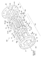
- FIG. 3 is a perspective view showing the expandable portion 140 of the guiding device 120. As shown in FIG. Although only one disc-like member 300 is shown in FIG. 3, in actuality, as shown in FIG. 2, the disc-like member 300 is in the thickness direction while being stacked in the thickness direction. It is transported. Moreover, in FIG. 3, the state at the time of looking at the expansion-contraction part 140 from the conveyance direction downstream side of the disk shaped member 300 is shown.
- FIG. 4A, 4B, and 4C are cross-sectional views of the stretchable portion 140.
- FIG. 4A is a cross-sectional view of the stretchable portion 140 taken along line IVA-IVA in FIG. 3
- FIG. 4B is a cross-sectional view of the stretchable portion 140 taken along line IVB-IVB in FIG. 4C is a cross-sectional view of the stretchable portion 140 taken along the line IVC-IVC of FIG.
- the stretchable portion 140 is provided with an upstream guide portion 400 for guiding the disk-shaped member 300 and a downstream guide portion 500 for guiding the disk-shaped member 300.
- the upstream guiding unit 400 guides the disc-like member 300 guided by the guiding device main body 130 (see FIG. 1).
- the downstream guiding unit 500 guides the disc-like member 300 guided and conveyed by the upstream guiding unit 400.
- the installation area of the upstream guide portion 400 and the installation area of the downstream guide portion 500 partially overlap in the transport direction of the disk-like member 300 (hereinafter simply referred to as “transport direction”).
- transport direction the transport direction of the disk-like member 300
- the guiding area GA in which the upstream guiding section 400 guides the disc-like member 300 and the guiding area GB in which the downstream guiding section 500 guides the disc-like member 300 are in the transport direction. Partially overlapping.
- the guide area GA in the transport direction which is the guide area by the upstream guide section 400
- the guide area GB in the transport direction which is the guide area by the downstream guide section 500. It partially overlaps in the transport direction.
- overlap portion GE a portion where the guide area GA where the upstream side guide portion 400 guides the disc-like member 300 and the guide area GB where the downstream side guide portion 500 guides the disc-like member 300 overlap
- the guidance of the disk-shaped member 300 by the downstream guiding unit 500 is started while the guiding of the disk-shaped member 300 by the upstream guiding unit 400 is being performed.
- the disc-like member 300 is guided by both the upstream guiding portion 400 and the downstream guiding portion 500 at the overlapping portion GE.
- the upstream guiding portion 400 is provided with a plurality of round rod-shaped upstream guiding members 410.
- the plurality of upstream guide members 410 are disposed along the transport path of the disc-like member 300 to be transported. Further, as shown in FIG. 4A, the plurality of upstream guide members 410 are disposed around the transport path of the disk-shaped member 300.
- the plurality of upstream guide members 410 are arranged such that the positions in the circumferential direction of the conveyed disk-shaped member 300 are different from each other. More specifically, the plurality of upstream guide members 410 are arranged to be placed on one circle (virtual circle) 420 located around the transport path of the disk-shaped member 300. In the present embodiment, the disc-like member 300 passes through the inside (the center side of the circle 420 on which the plurality of upstream guiding members 410 are placed) of the plurality of upstream guiding members 410 provided.
- the downstream guide portion 500 is also provided with a plurality of round rod-shaped downstream guide members 510.
- the plurality of downstream guide members 510 are also disposed around the transport path of the disk-shaped member 300, as shown in FIG. 4 (B). Furthermore, as shown in FIG. 4 (B), the plurality of downstream guide members 510 are also arranged such that the positions in the circumferential direction of the conveyed disc-like members 300 are different from each other.
- the plurality of downstream guide members 510 are also arranged to be placed on one circle (virtual circle) 520 located around the transport path of the disk-shaped member 300. ing. And, in the present embodiment, the disc-like member 300 passes through the inside of the plurality of downstream guide members 510 provided.
- the upstream guide member 410 and the downstream guide member 510 may be made of, for example, stainless steel as long as they have good corrosion resistance, scratch resistance, wear resistance, lubricity, strength and the like.
- the upstream guide member 410 and the downstream guide member 510 are not limited to stainless steel, and may be formed of other materials. Further, the upstream guide member 410 and the downstream guide member 510 may be configured such that the surface of a cylindrical base material is covered with a member made of a material other than the material of the base material.
- FIG. 4C is a cross-sectional view taken along line IVC-IVC of FIG.
- FIG. 4C is a cross-sectional view of a plane perpendicular to the transport direction of the disk-shaped member 300, which passes through both the upstream guide 400 and the downstream guide 500.
- FIG. 4C is a cross-sectional view in a plane perpendicular to the transport direction of the disk-like member 300 and passing through the overlapping portion GE.
- the guide area GA where the upstream guide section 400 guides the disc-like member 300 and the guide area GB where the downstream guide section 500 guides the disc-like member 300 overlap each other. Overlapping at GE. More specifically, in the present embodiment, the downstream guiding member 510 constituting the downstream guiding portion 500 is inserted between each of the upstream guiding members 410 constituting the upstream guiding portion 400. Thereby, the guide area GA by the upstream guide unit 400 and the guide area GB by the downstream guide unit 500 overlap.
- both the upstream guide member 410 and the downstream guide member 510 appear.
- the plurality of upstream guiding members 410 and the plurality of downstream guiding members 510 are placed on the same circle (virtual circle) 620. Further, in the circumferential direction of the same circle 620, the upstream guide member 410 and the downstream guide member 510 are alternately arranged.
- each position of the upstream guide member 410 and the downstream side The position of each of the guide members 510 is different.
- upstream guide members 410 are provided.
- the upstream guide member 410 is disposed at every 60 ° in the circumferential direction of the disc-like member 300.
- each of the downstream guide members 510 also has a regular hexagonal shape (not shown) whose central portion is located at the center CB of a circle 520 (see FIG. 4B) on which each of the downstream guide members 510 is placed. It is arranged to be located at the top.
- the downstream guide member 510 is disposed at an interval of 60 ° in the circumferential direction of the disc-like member 300. Furthermore, in the present embodiment, as shown in FIG. 4C, the upstream guide member 410 and the downstream guide member 510 are arranged at an interval of 30 ° in the circumferential direction of the disk-shaped member 300.
- the number of each of the upstream guide member 410 and the downstream guide member 510 is not particularly limited. However, the numbers of the upstream guide member 410 and the downstream guide member 510 need to be such that the disc-like member 300 does not fall.
- the preferred number of each of the upstream guide member 410 and the downstream guide member 510 is four to six.
- the reaction force acting on the disc 300 from the upstream guide 410 and the downstream guide 510 becomes large, and the disc 300 becomes difficult to move.
- the number of upstream guide members 410 and the number of downstream guide members 510 are too large, the cost of the moving apparatus 100 will increase.
- the gap (the difference between the inscribed circle with respect to the plurality of upstream guide members 410 and the diameter of the disc member 300) located between the upstream guide member 410 and the disc-like member 300 being transported is The size is set such that the disc-like member 300 is conveyed without stagnation.
- the gap (the difference between the inscribed circle for the plurality of downstream guiding members 510 and the diameter of the disc 300) between the downstream guiding member 510 and the disc 300 to be transported is also a disc. It is set to the size by which the rod-like member 300 is conveyed without stagnation.
- the gap is too small, clogging of the disk-shaped member 300 or damage to the outer peripheral edge of the disk-shaped member 300 is likely to occur. If the gap is too large, the disc-like member 300 may be inclined or clogging of the disc-like member 300 may easily occur. If the gap is too large, the disc-like member 300 may fall through the gap between the upstream guide members 410 adjacent to each other and the gap between the downstream guide members 510 adjacent to each other.
- the diameter of the circle 425 shown in FIG. 4A, the diameter of the circle 525 shown in FIG. 4B, and the diameter of the circle 625 shown in FIG. It is equal.
- the diameter of the inscribed circle for the plurality of upstream guide members 410 and the diameter of the inscribed circle for the plurality of downstream guide members 510 are equal to each other.
- the gap formed between the upstream guide member 410 and the disc-shaped member 300 and the gap formed between the downstream guide member 510 and the disc-shaped member 300 become equal. ing.
- a defect such as the disk-like member 300 being caught by the downstream side guide member 510 or the like is less likely to occur.
- the upstream guide portion 400 is provided with an annular (flange-like) first fixing member 430.
- the first fixing member 430 is fixed to a portion of the plurality of upstream guide members 410 provided on the downstream side in the transport direction. More specifically, the first fixing member 430 is fixed to the downstream end of the plurality of upstream guide members 410 provided.
- annular (flange-like) second fixing member 530 is also provided on the downstream side guide portion 500.
- the second fixing member 530 is fixed to a portion of the plurality of downstream guide members 510 provided on the upstream side in the transport direction. More specifically, the second fixing member 530 is fixed to the upstream end of the plurality of downstream guide members 510.
- the first fixing member 430 is a member connecting the plurality of upstream guide members 410
- the second fixing member 530 is a member connecting the plurality of downstream guiding members 510.
- the upstream side guide portion 400 is provided with the upstream side fixed member 440
- the downstream side guide portion 500 is provided with the downstream side fixed member 540.
- the upstream fixed member 440 is formed in an annular shape (flange shape). Further, the upstream fixed member 440 is fixed to the upstream end of the plurality of upstream guiding members 410.
- the upstream fixed member 440 has a function of connecting the upstream ends of the plurality of upstream guiding members 410. Further, the upstream fixed member 440 is fixed to the guiding device main body 130 (see FIG. 1), and positions the expandable portion 140 with respect to the guiding device main body 130.
- the downstream fixed member 540 is also formed in an annular shape (flange shape).
- the downstream fixed member 540 is fixed to the downstream end of the plurality of downstream guiding members 510.
- the downstream fixed member 540 has a function of connecting the plurality of downstream guiding members 510.
- the downstream fixed member 540 is fixed to a fixed location located downstream of the downstream fixed member 540. Specifically, the downstream fixed member 540 is fixed to the sealant application device 30 (see FIG. 1).
- Each of the upstream fixed member 440 and the downstream fixed member 540 is formed in an annular shape, and a plurality of through holes 80 formed along the thickness direction are formed inside the outer peripheral edge 68.
- a rod-like fastening member such as a bolt is passed through the through hole 80. Then, the upstream fixed member 440 is fixed to the guiding device main body 130 using this fastening member.
- the downstream fixed member 540 is fixed to the sealant application device 30 using this fastening member.
- the through hole 80 formed in the downstream fixed member 540 is formed in a long hole shape. More specifically, the through hole 80 formed in the downstream fixed member 540 is formed in an elongated hole shape extending along the circumferential direction of the downstream fixed member 540.
- the downstream fixed member 540 can be easily fixed to the fixing location as compared to the case where the through hole 80 is formed as a round hole.
- the through hole 80 when the through hole 80 is formed as a round hole, when the bolt hole or the like formed at the fixed location and the through hole 80 are deviated, the downstream fixed member 540 to the fixed location is fixed. It becomes difficult to fix the On the other hand, when the through hole 80 is formed as a long hole, the downstream fixed member 540 can be easily fixed to the fixing location.
- the through hole 80 formed in the downstream fixed member 540 is formed in a long hole shape, but the through hole 80 formed in the upstream fixed member 440 may be formed in a long hole shape. Further, the through hole 80 may have an elongated shape in both the upstream fixed member 440 and the downstream fixed member 540.
- the upstream fixed member 440 is fixed for fixing the upstream guide member 410 inside the through hole 80 in the radial direction of the upstream fixed member 440.
- a hole 81 is provided.
- the upstream guide member 410 is fixed to the upstream fixed member 440 by inserting the end of the upstream guide member 410 into the fixing hole 81 and performing a welding process.
- the upstream fixed member 440 has a passage through hole 83 for passing the disc-like member 300 at the central portion in the radial direction of the upstream fixed member 440. It is formed.
- downstream side fixed member 540 and in the downstream side fixed member 540, as shown in FIG. 3, the downstream side guide is provided inside the through hole 80 in the radial direction of the downstream side fixed member 540.
- a fixing hole 81 for fixing the member 510 is provided.
- the downstream guide member 510 is fixed to the downstream fixed member 540 by inserting the end of the downstream guide member 510 into the fixing hole 81 and performing a welding process.
- a passage through hole 83 for passing the disc-like member 300 is formed at the central portion in the radial direction of the downstream fixed member 540.
- through holes 95 are also formed in each of the first fixing member 430 and the second fixing member 530.
- a plurality of the through holes 95 are formed, and are arranged side by side along the circumferential direction of the first fixing member 430 and the second fixing member 530 and at predetermined regular intervals (at equal intervals). There is.
- one guiding portion of the upstream side guiding portion 400 and the downstream side guiding portion 500 is opposed to the other guiding portion.
- a through hole 83 for passage of the disc-like member 300 is formed at the central portion in the radial direction.
- each of the plurality of upstream guiding members 410 is passed through the through hole 95 of the second fixing member 530, and each of the plurality of downstream guiding members 510 is the first The through holes 95 of the fixing member 430 of FIG.
- the upstream guide member 410 is passed through the through holes 95 located at every other of the plurality of through holes 95 formed in the second fixing member 530. Furthermore, in the present embodiment, among the plurality of through holes 95 formed in the second fixing member 530, the downstream side with respect to the through hole 95 located between the through holes 95 through which the upstream guide member 410 passes. The end (upstream end) of the side guide member 510 is inserted.
- the second fixing member 530 is formed with the same number of through holes 95 as the total value of the number of installed upstream guide members 410 and the number of installed downstream guide members 510. Then, in the present embodiment, the upstream guide member 410 is passed through a part of the through hole 95, and the end of the downstream guide member 510 is inserted into the other part of the through hole 95. More specifically, in the second fixing member 530, twelve through holes 95 are formed. The upstream guide member 410 is passed through the six through holes 95, and the end of the downstream guide member 510 is inserted into the other six through holes 95.
- downstream guide member 510 is passed through the through holes 95 located at every other one of the plurality of through holes 95 formed in the first fixing member 430. Furthermore, in the present embodiment, among the plurality of through holes 95 formed in the first fixing member 430, the upstream side with respect to the through hole 95 positioned between the through holes 95 through which the downstream guide member 510 is passed. The end (downstream end) of the side guide member 410 is inserted.
- the first fixing member 430 is formed with the same number of through holes 95 as the total value of the number of installed upstream guide members 410 and the number of installed downstream guide members 510,
- the downstream guide member 510 is passed through a part of the through hole 95, and the end of the upstream guide member 410 is inserted into the other part of the through hole 95.
- twelve through holes 95 are formed in the first fixing member 430.
- the downstream guide member 510 is passed through the six through holes 95, and the end of the upstream guide member 410 is inserted into the other six through holes 95.
- screw through holes 98 corresponding to the respective through holes 95 are formed.
- a helical internal thread is formed on the inner peripheral surface 98A of the through hole 98 for screw.
- the screw through holes 98 are formed from the outer peripheral surface 92 of each of the first fixing member 430 and the second fixing member 530 toward the passing through hole 83.
- fixing of (the downstream end portion 410A of) the upstream guide member 410 to the first fixing member 430 is performed by attaching a screw to the screw through hole 98 (screw through hole 98 indicated by reference numeral 3A). This is performed by pressing the tip of this screw against the upstream guide member 410.
- fixing of (the upstream end 510A of) the downstream guide member 510 to the second fixing member 530 is performed by attaching a screw to the screw through hole 98 (screw through hole 98 shown by reference numeral 3B) This is performed by pressing the tip end of the lower guide member against the downstream guide member 510.
- a screw is attached to the screw through hole 98 (the screw through hole 98 indicated by reference numeral 3C) of the first fixing member 430, and the tip of the screw is pressed against the downstream guide member 510. And fix the upstream guiding portion 400 to the downstream guiding portion 500. Further, in the present embodiment, a screw is attached to the screw through hole 98 (the screw through hole 98 indicated by reference numeral 3D) of the second fixing member 530, and the tip of the screw is pressed against the upstream guide member 410. And fix the downstream side guiding unit 500 to the upstream side guiding unit 400.
- the first fixing member 430, the second fixing member 530, the upstream fixed member 440, and the downstream fixed member 540 have rust resistance, scratch resistance, wear resistance, lubricity, strength, and the like. It is good if it is good, and it is preferable to form with stainless steel. In addition, you may form not only stainless steel but another material.
- the first fixing member 430, the second fixing member 530, the upstream fixed member 440, and the downstream fixed member 540 are made of a material other than the material of the annular member. It may be a coated configuration.
- one of the guide portions of the upstream side guide portion 400 and the downstream side guide portion 500 is configured to be able to move forward and backward with respect to the other guide portion. Changes. More specifically, in the present embodiment, the downstream guide member 510, the second fixing member 530, and the downstream fixed member 540 are integrated into a unit. Then, for example, by moving the unitized portion toward the upstream guide portion 400, the stretchable portion 140 is contracted. Also, conversely, by moving the unitized part in a direction away from the upstream guide 400 side, the stretchable part 140 is extended.
- the upstream guide member 410, the first fixing member 430, and the upstream fixed member 440 are integrated into a unit, and the unitized portion is moved to the downstream guide 500 side.
- the stretchable portion 140 shrinks.
- this unitized part is extended.
- two unitized parts are provided, and the two unitized parts are disposed such that a part thereof overlaps in the transport direction, and further, the discoid member 300 Are arranged in a mutually offset state in the circumferential direction. And in this embodiment, if one unitized part is advanced or retracted with respect to the other unitized part, the expansion-contraction part 140 will contract or the expansion-contraction part 140 will expand.
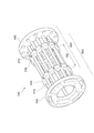
- FIG. 5 is a view showing the state of the stretchable portion 140 after the stretchable portion 140 is shrunk.
- the stretchable portion 140 is contracted, the upstream fixed member 440 and the downstream fixed member 540 come closer to each other. Thereby, the full length of the expansion-contraction part 140 becomes small.
- the stretchable portion 140 is contracted, the length of the overlapping portion GE located between the first fixing member 430 and the second fixing member 530 (the length of the first fixing member 430 and the second fixing member 530 Separation distance) becomes large.
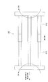
- FIG. 6 is a view showing the state of the stretchable portion 140 after the stretchable portion 140 is stretched.
- the stretchable portion 140 extends, the upstream fixed member 440 and the downstream fixed member 540 are separated from each other. Thereby, in the present embodiment, the total length of the stretchable portion 140 is increased.
- the stretchable portion 140 is extended, the length of the overlapping portion GE located between the first fixing member 430 and the second fixing member 530 (the length of the first fixing member 430 and the second fixing member 530 The separation distance is smaller.
- the upstream guide member 410 and the downstream guide member 510 The clearance (clearance) between the disk-shaped member 300 is constant.
- the moving device 100 is installed between various processing devices, and the disk-shaped member 300 is moved between the processing devices.
- the total length of the moving apparatus 100 may become larger than necessary due to dimensional tolerances of the respective apparatuses, installation errors, etc.
- the total length of 100 may be smaller than the required length.
- the total length of the moving apparatus 100 when the total length of the moving apparatus 100 is increased or decreased, installation of the moving apparatus 100 and the processing apparatus takes time and effort. Specifically, when the total length of the moving device 100 is increased, it is necessary to cut and polish members constituting the moving device 100, which requires time and effort. In addition, when the total length of the transfer device 100 is reduced, for example, it is necessary to remove the end portion of the transfer device 100, which has already been assembled, to manufacture a longer end portion, and then to attach the long end portion.
- the stretchable portion 140 when the total length of the moving device 100 is larger or smaller than necessary, the stretchable portion 140 is stretched or the stretchable portion 140 is shrunk. More specifically, at least one of the upstream guide portion 400 and the downstream guide portion 500 is moved along the conveying direction of the disc-like member 300. Thereby, in the present embodiment, the entire length of the mobile apparatus 100 can be changed more easily.
- the first fixing member 430 (see FIG. 3) is fixed to the downstream guiding member 510, and the second fixing member 530 is guided upstream. It is fixed to the member 410.
- a plurality of first fixing members 430 can be provided. It is fixed to each of the provided downstream guide members 510.
- a plurality of second fixing members 530 are provided by attaching a screw to each of the screw through holes 98 of the second fixing member 530 (the screw through holes 98 indicated by reference numeral 3D in FIG. 3). It is fixed to each of the upstream guide members 410.
- the first fixing member 430 is fixed to each of the downstream side guiding members 510
- the second fixing member 530 is fixed to each of the upstream side guiding members 410.
- the plurality of downstream guide members 510 in the longitudinal direction are fixed to the upstream guide portion 400 in the longitudinal direction.
- a plurality of locations in the longitudinal direction of each of the plurality of upstream guide members 410 provided are fixed to the downstream guide portion 500.
- the downstream guiding member 510 is fixed to the upstream guiding portion 400 (upstream guiding member 410) at a portion where the second fixing member 530 is provided, and the first fixing The portion where the member 430 is provided is fixed to the upstream guiding portion 400 (upstream guiding member 410).
- the downstream guiding member 510 is fixed to the upstream guiding portion 400 at two places, where the first fixing member 430 is provided and where the second fixing member 530 is provided.
- downstream side guide member 510 is fixed to the upstream side guide part 400 (upstream side guide member 410) at two points shown by 3X and 3Y in FIG.
- downstream guiding member 510 is fixed to the upstream guiding member 410 via the first fixing member 430 and the second fixing member 530 which are different in the installation position in the transport direction. Thereby, a plurality of locations in the longitudinal direction of each of the downstream guide members 510 are fixed to the upstream guide portion 400.
- the upstream guiding member 410 is fixed to the downstream guiding portion 500 (the downstream guiding member 510) at a portion where the first fixing member 430 is provided, and the second fixing member 530 is provided. It fixes to the downstream guide part 500 (downstream side guide member 510) in the part currently carried out.
- the upstream guiding member 410 is fixed to the downstream guiding portion 500 at two places, where the first fixing member 430 is provided and where the second fixing member 530 is provided. Ru. More specifically, the upstream guide member 410 is fixed to the downstream guide portion 500 (downstream guide member 510) at two points indicated by reference numerals 3X and 3Y in FIG.
- the upstream guide member 410 is fixed to the downstream guide member 510 via the first fixing member 430 and the second fixing member 530 which are different in the installation position in the transport direction.
- a plurality of locations in the longitudinal direction of each of the plurality of upstream guide members 410 are fixed to the downstream guide portion 500.
- cover member In the present embodiment, after the expansion and contraction of the expansion and contraction part 140 is completed and the upstream guide part 400 and the downstream guide part 500 are mutually fixed using the above-mentioned screw, the upstream guide member 410 and the downstream guide member 510 A cover member 89 made of a resin material is attached to each of the above. In addition, the cover member 89 is similarly attached also to the guide member 131 provided in the guide apparatus main-body part 130 (refer FIG. 1).
- FIG. 7 is a cross-sectional view taken along the line VII-VII in FIG. 3 and shows a cross-sectional view after the cover member 89 is attached.
- FIG. 7 shows a state after the cover member 89 is attached to the portion of the upstream guide member 410 located between the upstream fixed member 440 and the second fixing member 530.
- a cover member 89 made of a resin material and having a C-shaped cross section is attached to each of the upstream guide members 410.
- cover member 89 is also attached to the upstream guide member 410 and the downstream guide member 510 located at the overlapping portion GE. In addition, the cover member 89 is also attached to a portion of the downstream guide member 510 located between the first fixing member 430 and the downstream fixed member 540 (a portion shown by reference numeral 3H in FIG. 3).
- FIG. 8 is a cross-sectional view of the stretchable portion 140 taken along line VIII-VIII in FIG. 4 (B).
- the state of the cross section in the entire area in the longitudinal direction of the stretchable portion 140 is displayed.
- the upstream guide member 410 which is not originally present on the line VIII-VIII in FIG. 4 (B) is also displayed.
- the cover member 89 is also displayed.
- each of the upstream fixed member 440, the downstream fixed member 540, the first fixing member 430, and the second fixing member 530 It is tapered. Specifically, in each of the upstream fixed member 440, the downstream fixed member 540, the first fixing member 430, and the second fixing member 530, the diameter of the inner circumferential surface 79 is not constant, and a disc-like member is used. The diameter of the inner circumferential surface 79 becomes larger as it goes upstream in the conveying direction of 300.
- each of the upstream fixed member 440, the downstream fixed member 540, the first fixing member 430, and the second fixing member 530 is the inner peripheral surface as it goes to the upstream side in the transport direction. It is tapered to increase the diameter of 79. Accordingly, in the present embodiment, each of the upstream fixed member 440, the downstream fixed member 540, the first fixing member 430, and the second fixing member 530 is compared with the case where no taper is provided. The disc-like member 300 can easily pass through.
- the surface of the cover member 89 is positioned closer to the center of the conveyance path of the discoid member 300 than the upstream end 79A of the inner circumferential surface 79. doing. More specifically, when the upstream end 79A is compared with the surface of the cover member 89 located upstream of the upstream end 79A, the surface of the cover member 89 is the upstream end. It is located on the center side of the conveyance path of the disk-shaped member 300 rather than 79A.
- the upstream end 79A is less likely to be caught by the disk-like member 300 than the case where the upstream end 79A is positioned closer to the center of the transport path than the surface of the cover member 89.
- the discoid member 300 is transported smoothly.
- the downstream end 79B of the inner circumferential surface 79 is located closer to the center of the conveyance path of the discoid member 300 than the surface of the cover member 89. doing. More specifically, when the downstream end 79B is compared with the surface of the cover member 89 located downstream of the downstream end 79B, the downstream end 79B is the same as that of the cover 89. It is located on the center side of the conveyance path of the disk-shaped member 300 than the surface. As a result, the surface of the cover member 89 is less likely to be caught by the disc-like member 300 on the cover member 89 than when it is located closer to the center of the transport path than the downstream end 79B. The disc-like member 300 is smoothly transported.
- FIG. 9 is a view showing a comparative example of the stretchable part 140. As shown in FIG. In addition, in FIG. 9, the state when the expansion-contraction part 140 is seen from the side is shown.
- the upstream guide member 410 and the downstream guide member 510 are coaxially arranged. Further, the upstream guide member 410 is formed in a cylindrical shape, and the downstream guide member 510 is configured to enter the upstream guide member 410.
- the downstream side guide member 510 moves in and out of the upstream side guide member 410, the total length of the stretchable part 140 changes.
- the upstream guide member 410 and the downstream guide member 510 interfere with each other.
- this interference is avoided by making the upstream guide member 410 a hollow cylindrical member.
- the upstream guiding member 410 and the downstream guiding member 510 are not coaxially arranged, and the installation position of the upstream guiding member 410 in the circumferential direction of the discoid member 300 And the installation position of the downstream guide member 510 are different.
- both the upstream guide member 410 and the downstream guide member 510 can be made solid members, and the reduction in the strength of the stretchable portion 140 is unlikely to occur.
- the stretchable portion 140 when a rotational moment as shown by an arrow 9A in the drawing acts on the upstream side guide member 410 and the downstream side guide member 510, deformation of the stretchable portion 140 tends to occur. More specifically, the stretchable portion 140 is bent, for example, around the central portion in the longitudinal direction of the stretchable portion 140 (around the junction of the upstream guide member 410 and the downstream guide member 510); Deformation is likely to occur. In addition, in the comparative example, when a load to move the end portions on the free end side of the upstream guide member 410 and the downstream guide member 510 in the direction intersecting the transport direction acts on the stretchable portion 140, Deformation of the stretchable portion 140 is likely to occur.
- a plurality of locations in the longitudinal direction of each of the downstream guide members 510 are fixed to the upstream guide portion 400.
- a plurality of locations in the longitudinal direction of each of the upstream guide members 410 are fixed to the downstream guide portion 500. In this case, even if a load acting in the direction intersecting the transport direction acts on the stretchable portion 140, deformation of the stretchable portion 140 is less likely to occur.
- the upstream guide member 410 when the upstream guide member 410 is formed in a cylindrical shape and the downstream guide member 510 is inserted into the upstream guide member 410, the upstream guide member 410 and the downstream guide member 510 there is a level difference at the junction of On the other hand, in the configuration of the present embodiment, the occurrence of the step can be suppressed, and the discoid member 300 can be transported more smoothly.
- the stretchable parts 140 may be vertically or diagonally (a direction crossing the horizontal direction and the vertical direction) It may be arranged along).
- each of the upstream guide member 410 and the downstream guide member 510 is given a predetermined curvature. It is also good.
- the overall length of the stretchable part 140 is changed by moving at least one of the upstream guide 400 and the downstream guide 500 along an arc-shaped transport path having this curvature.
- the moving apparatus 100 was installed in the manufacturing process of the can lid was demonstrated above, you may install the moving apparatus 100 in the manufacturing process of a beverage can. Also in the manufacturing process of the beverage can, the disc-like member 300 (the disc-like member 300 with the tab attached thereto (the disc-like member 300 in a state of being completed as a can lid)) is transported. Also in this case, the total length of the moving device 100 may be larger than necessary or the total length of the moving device 100 may be smaller than the necessary length, due to dimensional tolerances of the respective devices as described above.
- each processing apparatus can be performed more easily also in the process of manufacturing a beverage can (a factory for manufacturing a beverage can).
- the attachment apparatus is provided and the disk shaped member 300 (The disk shaped member 300 to which the tab was attached is attached with respect to the opening part of the can main body after being filled with the drink through the opening part. Attach).
- the disc-like member 300 is placed on the can body, bending is performed on both the outer peripheral edge of the disc-like member 300 and the opening edge of the can body, to the opening of the can body.
- the disc-shaped member 300 is attached.
- the disc-like member 300 is attached to the opening of the can body by so-called tightening. This completes the beverage can filled with the beverage.
Landscapes
- Engineering & Computer Science (AREA)
- Mechanical Engineering (AREA)
- Automation & Control Theory (AREA)
- Framework For Endless Conveyors (AREA)
- Structure Of Belt Conveyors (AREA)
- Attitude Control For Articles On Conveyors (AREA)
- Electroplating Methods And Accessories (AREA)
- Feeding Of Articles To Conveyors (AREA)
Priority Applications (3)
| Application Number | Priority Date | Filing Date | Title |
|---|---|---|---|
| US16/648,231 US11213876B2 (en) | 2017-10-05 | 2018-07-02 | Guidance device, device for moving disc-shaped member, can lid manufacturing system and beverage can manufacturing system |
| CN201880059928.3A CN111093855B (zh) | 2017-10-05 | 2018-07-02 | 引导装置、圆盘状构件移动装置、罐盖制造系统以及饮料罐制造系统 |
| EP18864335.7A EP3693097B1 (en) | 2017-10-05 | 2018-07-02 | Guidance device, device for moving disc-shaped member, can lid manufacturing system, and beverage can manufacturing system |
Applications Claiming Priority (2)
| Application Number | Priority Date | Filing Date | Title |
|---|---|---|---|
| JP2017195051A JP6843724B2 (ja) | 2017-10-05 | 2017-10-05 | 案内装置、円盤状部材移動装置、缶蓋製造システム、および、飲料缶製造システム |
| JP2017-195051 | 2017-10-05 |
Publications (1)
| Publication Number | Publication Date |
|---|---|
| WO2019069517A1 true WO2019069517A1 (ja) | 2019-04-11 |
Family
ID=65995124
Family Applications (1)
| Application Number | Title | Priority Date | Filing Date |
|---|---|---|---|
| PCT/JP2018/025067 Ceased WO2019069517A1 (ja) | 2017-10-05 | 2018-07-02 | 案内装置、円盤状部材移動装置、缶蓋製造システム、および、飲料缶製造システム |
Country Status (5)
| Country | Link |
|---|---|
| US (1) | US11213876B2 (2) |
| EP (1) | EP3693097B1 (2) |
| JP (1) | JP6843724B2 (2) |
| CN (1) | CN111093855B (2) |
| WO (1) | WO2019069517A1 (2) |
Families Citing this family (2)
| Publication number | Priority date | Publication date | Assignee | Title |
|---|---|---|---|---|
| EP3075772B1 (de) | 2015-04-02 | 2020-08-26 | tesa SE | Wiederablösbarer haftklebestreifen |
| CN113582105A (zh) * | 2021-08-19 | 2021-11-02 | 广州达意隆包装机械股份有限公司 | 可伸缩供盖滑道及封盖系统 |
Citations (2)
| Publication number | Priority date | Publication date | Assignee | Title |
|---|---|---|---|---|
| JPS6310947U (2) * | 1986-07-08 | 1988-01-25 | ||
| JPH01118833U (2) | 1988-01-29 | 1989-08-11 |
Family Cites Families (16)
| Publication number | Priority date | Publication date | Assignee | Title |
|---|---|---|---|---|
| US2720302A (en) * | 1953-09-09 | 1955-10-11 | Homer W Madden | Telescopic can and package conveying chute |
| US2717089A (en) * | 1953-12-23 | 1955-09-06 | American Can Co | Apparatus for manually bulk loading cans into freight cars and other compartments |
| US3618550A (en) * | 1970-01-26 | 1971-11-09 | Fleetwood Syst Inc | Method and apparatus for controlling the supply in a can end processing system |
| JPS5434747Y2 (2) * | 1977-04-26 | 1979-10-23 | ||
| JPS5434747A (en) | 1977-08-24 | 1979-03-14 | Victor Co Of Japan Ltd | Fm demodulation circuit of phase tracking loop system |
| JPS6310947A (ja) | 1986-07-02 | 1988-01-18 | Nippon Telegr & Teleph Corp <Ntt> | 音声パケツト送受信方式 |
| US4795018A (en) * | 1987-04-22 | 1989-01-03 | Anderson Jon V | Contained trackwork for can conveying |
| DE3717037A1 (de) | 1987-05-21 | 1988-12-08 | Basf Ag | Photopolymerisierbare aufzeichnungsmaterialien sowie photoresistschichten und flachdruckplatten auf basis dieser aufzeichnungsmaterialien |
| US5161919A (en) * | 1991-08-06 | 1992-11-10 | Simplimatic Engineering Company | Bottle air conveyor |
| CN1081941A (zh) * | 1992-08-11 | 1994-02-16 | 雷诺兹金属公司 | 罐头盖成型的方法和装置 |
| JPH0952133A (ja) * | 1995-08-16 | 1997-02-25 | Mitsubishi Heavy Ind Ltd | 缶蓋供給装置 |
| US7721876B2 (en) * | 2006-10-27 | 2010-05-25 | Illinois Tool Works Inc. | Adjustable side rails for article conveying system, and conveyor and system incorporating same |
| CN102814426B (zh) * | 2012-07-19 | 2015-01-28 | 东莞市精丽制罐有限公司 | 罐体生产系统 |
| CA2882922C (en) * | 2014-02-21 | 2020-12-01 | Septimatech Group Inc. | Guide rail system with cover element |
| CN204524085U (zh) * | 2014-12-31 | 2015-08-05 | 广州市金峰机械科技有限公司 | 一种气雾罐面盖自动冲压机 |
| JP6727098B2 (ja) * | 2016-10-26 | 2020-07-22 | 昭和アルミニウム缶株式会社 | 力測定方法および力測定装置 |
-
2017
- 2017-10-05 JP JP2017195051A patent/JP6843724B2/ja active Active
-
2018
- 2018-07-02 US US16/648,231 patent/US11213876B2/en active Active
- 2018-07-02 WO PCT/JP2018/025067 patent/WO2019069517A1/ja not_active Ceased
- 2018-07-02 CN CN201880059928.3A patent/CN111093855B/zh active Active
- 2018-07-02 EP EP18864335.7A patent/EP3693097B1/en active Active
Patent Citations (2)
| Publication number | Priority date | Publication date | Assignee | Title |
|---|---|---|---|---|
| JPS6310947U (2) * | 1986-07-08 | 1988-01-25 | ||
| JPH01118833U (2) | 1988-01-29 | 1989-08-11 |
Also Published As
| Publication number | Publication date |
|---|---|
| JP6843724B2 (ja) | 2021-03-17 |
| CN111093855B (zh) | 2022-02-22 |
| EP3693097B1 (en) | 2023-09-06 |
| EP3693097C0 (en) | 2023-09-06 |
| CN111093855A (zh) | 2020-05-01 |
| EP3693097A4 (en) | 2021-06-30 |
| EP3693097A1 (en) | 2020-08-12 |
| JP2019063855A (ja) | 2019-04-25 |
| US20200261960A1 (en) | 2020-08-20 |
| US11213876B2 (en) | 2022-01-04 |
Similar Documents
| Publication | Publication Date | Title |
|---|---|---|
| ES2865277T3 (es) | Cojinete con segmentos de reborde | |
| JP6109064B2 (ja) | 溶接ワイヤ用矯正装置 | |
| WO2019069517A1 (ja) | 案内装置、円盤状部材移動装置、缶蓋製造システム、および、飲料缶製造システム | |
| US20140263327A1 (en) | Container End Closure with Buckle Control Feature | |
| US20130153705A1 (en) | Retainer for welding wire container and welding wire container with retainer | |
| JPS62502057A (ja) | 転動形荷重担体用軸受とその製造方法 | |
| WO2022066552A1 (en) | Roller conveyor gap blocker | |
| JPWO2013035378A1 (ja) | 缶蓋の巻き締め方法 | |
| EP3333133B1 (en) | Sleeve for glass tube molding and method of manufacturing a glass tube using the sleeve | |
| CA3010339A1 (en) | Pipe spacing wedge systems | |
| JP6707562B2 (ja) | 物品をカールさせるための方法および装置 | |
| CN101098817A (zh) | 椭圆横截面管、用于制造该产品的方法和设备 | |
| WO2014057737A1 (ja) | 円筒容器の製造方法 | |
| US20110192940A1 (en) | Pipe locator and support | |
| US20050023770A1 (en) | Pressure energized metallic seal | |
| US2947401A (en) | Flexible chute | |
| US7516522B2 (en) | Clamping collar | |
| US4795018A (en) | Contained trackwork for can conveying | |
| KR101226101B1 (ko) | 기판 이송장치용 이송롤러 | |
| US9656773B2 (en) | Bottle filling/capping methods and apparatus | |
| US10059526B2 (en) | Railing support | |
| US20160363244A1 (en) | Pipe clamp with worm drive mechanism | |
| US3969032A (en) | Rod splice | |
| EP3266600B1 (en) | Bead core forming former | |
| AU2020402848B2 (en) | Container rotator apparatus for a container manufacturing line |
Legal Events
| Date | Code | Title | Description |
|---|---|---|---|
| 121 | Ep: the epo has been informed by wipo that ep was designated in this application |
Ref document number: 18864335 Country of ref document: EP Kind code of ref document: A1 |
|
| NENP | Non-entry into the national phase |
Ref country code: DE |
|
| ENP | Entry into the national phase |
Ref document number: 2018864335 Country of ref document: EP Effective date: 20200506 |