WO2019073602A1 - Pompe à engrenages ou moteur - Google Patents
Pompe à engrenages ou moteur Download PDFInfo
- Publication number
- WO2019073602A1 WO2019073602A1 PCT/JP2017/037223 JP2017037223W WO2019073602A1 WO 2019073602 A1 WO2019073602 A1 WO 2019073602A1 JP 2017037223 W JP2017037223 W JP 2017037223W WO 2019073602 A1 WO2019073602 A1 WO 2019073602A1
- Authority
- WO
- WIPO (PCT)
- Prior art keywords
- side plate
- gear
- sliding surface
- gear pump
- gears
- Prior art date
- Legal status (The legal status is an assumption and is not a legal conclusion. Google has not performed a legal analysis and makes no representation as to the accuracy of the status listed.)
- Ceased
Links
Images


Classifications
-
- F—MECHANICAL ENGINEERING; LIGHTING; HEATING; WEAPONS; BLASTING
- F04—POSITIVE - DISPLACEMENT MACHINES FOR LIQUIDS; PUMPS FOR LIQUIDS OR ELASTIC FLUIDS
- F04C—ROTARY-PISTON, OR OSCILLATING-PISTON, POSITIVE-DISPLACEMENT MACHINES FOR LIQUIDS; ROTARY-PISTON, OR OSCILLATING-PISTON, POSITIVE-DISPLACEMENT PUMPS
- F04C2/00—Rotary-piston machines or pumps
- F04C2/08—Rotary-piston machines or pumps of intermeshing-engagement type, i.e. with engagement of co-operating members similar to that of toothed gearing
- F04C2/12—Rotary-piston machines or pumps of intermeshing-engagement type, i.e. with engagement of co-operating members similar to that of toothed gearing of other than internal-axis type
- F04C2/14—Rotary-piston machines or pumps of intermeshing-engagement type, i.e. with engagement of co-operating members similar to that of toothed gearing of other than internal-axis type with toothed rotary pistons
-
- F—MECHANICAL ENGINEERING; LIGHTING; HEATING; WEAPONS; BLASTING
- F04—POSITIVE - DISPLACEMENT MACHINES FOR LIQUIDS; PUMPS FOR LIQUIDS OR ELASTIC FLUIDS
- F04C—ROTARY-PISTON, OR OSCILLATING-PISTON, POSITIVE-DISPLACEMENT MACHINES FOR LIQUIDS; ROTARY-PISTON, OR OSCILLATING-PISTON, POSITIVE-DISPLACEMENT PUMPS
- F04C15/00—Component parts, details or accessories of machines, pumps or pumping installations, not provided for in groups F04C2/00 - F04C14/00
- F04C15/0003—Sealing arrangements in rotary-piston machines or pumps
- F04C15/0023—Axial sealings for working fluid
- F04C15/0026—Elements specially adapted for sealing of the lateral faces of intermeshing-engagement type machines or pumps, e.g. gear machines or pumps
-
- F—MECHANICAL ENGINEERING; LIGHTING; HEATING; WEAPONS; BLASTING
- F01—MACHINES OR ENGINES IN GENERAL; ENGINE PLANTS IN GENERAL; STEAM ENGINES
- F01C—ROTARY-PISTON OR OSCILLATING-PISTON MACHINES OR ENGINES
- F01C1/00—Rotary-piston machines or engines
- F01C1/08—Rotary-piston machines or engines of intermeshing engagement type, i.e. with engagement of co- operating members similar to that of toothed gearing
- F01C1/12—Rotary-piston machines or engines of intermeshing engagement type, i.e. with engagement of co- operating members similar to that of toothed gearing of other than internal-axis type
- F01C1/14—Rotary-piston machines or engines of intermeshing engagement type, i.e. with engagement of co- operating members similar to that of toothed gearing of other than internal-axis type with toothed rotary pistons
-
- F—MECHANICAL ENGINEERING; LIGHTING; HEATING; WEAPONS; BLASTING
- F03—MACHINES OR ENGINES FOR LIQUIDS; WIND, SPRING, OR WEIGHT MOTORS; PRODUCING MECHANICAL POWER OR A REACTIVE PROPULSIVE THRUST, NOT OTHERWISE PROVIDED FOR
- F03C—POSITIVE-DISPLACEMENT ENGINES DRIVEN BY LIQUIDS
- F03C2/00—Rotary-piston engines
- F03C2/08—Rotary-piston engines of intermeshing-engagement type, i.e. with engagement of co- operating members similar to that of toothed gearing
-
- F—MECHANICAL ENGINEERING; LIGHTING; HEATING; WEAPONS; BLASTING
- F04—POSITIVE - DISPLACEMENT MACHINES FOR LIQUIDS; PUMPS FOR LIQUIDS OR ELASTIC FLUIDS
- F04C—ROTARY-PISTON, OR OSCILLATING-PISTON, POSITIVE-DISPLACEMENT MACHINES FOR LIQUIDS; ROTARY-PISTON, OR OSCILLATING-PISTON, POSITIVE-DISPLACEMENT PUMPS
- F04C15/00—Component parts, details or accessories of machines, pumps or pumping installations, not provided for in groups F04C2/00 - F04C14/00
- F04C15/0042—Systems for the equilibration of forces acting on the machines or pump
- F04C15/0046—Internal leakage control
-
- F—MECHANICAL ENGINEERING; LIGHTING; HEATING; WEAPONS; BLASTING
- F04—POSITIVE - DISPLACEMENT MACHINES FOR LIQUIDS; PUMPS FOR LIQUIDS OR ELASTIC FLUIDS
- F04C—ROTARY-PISTON, OR OSCILLATING-PISTON, POSITIVE-DISPLACEMENT MACHINES FOR LIQUIDS; ROTARY-PISTON, OR OSCILLATING-PISTON, POSITIVE-DISPLACEMENT PUMPS
- F04C2/00—Rotary-piston machines or pumps
- F04C2/08—Rotary-piston machines or pumps of intermeshing-engagement type, i.e. with engagement of co-operating members similar to that of toothed gearing
- F04C2/12—Rotary-piston machines or pumps of intermeshing-engagement type, i.e. with engagement of co-operating members similar to that of toothed gearing of other than internal-axis type
- F04C2/14—Rotary-piston machines or pumps of intermeshing-engagement type, i.e. with engagement of co-operating members similar to that of toothed gearing of other than internal-axis type with toothed rotary pistons
- F04C2/18—Rotary-piston machines or pumps of intermeshing-engagement type, i.e. with engagement of co-operating members similar to that of toothed gearing of other than internal-axis type with toothed rotary pistons with similar tooth forms
-
- F—MECHANICAL ENGINEERING; LIGHTING; HEATING; WEAPONS; BLASTING
- F04—POSITIVE - DISPLACEMENT MACHINES FOR LIQUIDS; PUMPS FOR LIQUIDS OR ELASTIC FLUIDS
- F04C—ROTARY-PISTON, OR OSCILLATING-PISTON, POSITIVE-DISPLACEMENT MACHINES FOR LIQUIDS; ROTARY-PISTON, OR OSCILLATING-PISTON, POSITIVE-DISPLACEMENT PUMPS
- F04C2210/00—Fluid
- F04C2210/20—Fluid liquid, i.e. incompressible
-
- F—MECHANICAL ENGINEERING; LIGHTING; HEATING; WEAPONS; BLASTING
- F04—POSITIVE - DISPLACEMENT MACHINES FOR LIQUIDS; PUMPS FOR LIQUIDS OR ELASTIC FLUIDS
- F04C—ROTARY-PISTON, OR OSCILLATING-PISTON, POSITIVE-DISPLACEMENT MACHINES FOR LIQUIDS; ROTARY-PISTON, OR OSCILLATING-PISTON, POSITIVE-DISPLACEMENT PUMPS
- F04C2230/00—Manufacture
- F04C2230/60—Assembly methods
-
- F—MECHANICAL ENGINEERING; LIGHTING; HEATING; WEAPONS; BLASTING
- F05—INDEXING SCHEMES RELATING TO ENGINES OR PUMPS IN VARIOUS SUBCLASSES OF CLASSES F01-F04
- F05B—INDEXING SCHEME RELATING TO WIND, SPRING, WEIGHT, INERTIA OR LIKE MOTORS, TO MACHINES OR ENGINES FOR LIQUIDS COVERED BY SUBCLASSES F03B, F03D AND F03G
- F05B2210/00—Working fluid
- F05B2210/10—Kind or type
- F05B2210/11—Kind or type liquid, i.e. incompressible
Definitions
- the present invention relates to a gear pump or motor that delivers hydraulic fluid by using tooth spaces of a drive gear and a driven gear that form a meshing gear pair.
- a casing 1 internally provided with a gear storage chamber 11a for storing a pair of gears 2 and 3, and a side plate interposed between the casing 1 and the gears 2 and 3 6 and the non-sliding surface 6b opposite to the sliding surface 6a which is the surface of the side plate 6 facing the gears 2 and 3, and the space between the non-sliding surface 6b and the casing 1
- the gear pump or motor provided with the gasket 8 that divides the pressure into the high pressure side and the low pressure side, the sliding surface 6a of the side plate 6 is processed to suppress the friction between the gears 2, 3 and the side plate 6. The thing is widely done.
- a flat portion 6p is provided at a position corresponding to the meshing position of the pair of gears 2 and 3 in the side plate 6, and the hydraulic fluid leaks from the high pressure side to the low pressure side.
- this flat portion 6p suppresses the generation of abnormal noise due to the hydraulic fluid in the space defined by the side plate 6 and the teeth of the gears 2 and 3 being compressed in the space.
- the hydraulic fluid in the space defined by the side plate 6 and the teeth of the gears 2 and 3 is delivered after delivery of the gear pump or motor.
- noise such as noise caused by compression in the space resonates with the gear pump or the vehicle body of a vehicle equipped with the motor, a problem such as a large noise may occur. It may be overlooked.
- the present invention focuses on the above points, and has an object to enable early detection that the side plate is mounted in an incorrect posture, such as the reverse of the front and back, and the high pressure part and the low pressure part are reversed.
- the gear pump or motor according to the present invention has a configuration as described below. That is, the gear pump or motor according to the present invention comprises: a casing internally provided with a gear storage chamber for storing a pair of gears; a side plate interposed between the casing and the gear; and a surface of the side plate facing the gear And a gasket provided on a non-sliding surface opposite to the sliding surface and defining a space between the non-sliding surface and the casing into a high pressure side and a low pressure side,
- the attitude of the side plate is other than the predetermined attitude, the flow efficiency is reduced as compared with the case where the attitude of the side plate is the predetermined attitude.
- a flat portion is provided at a location corresponding to the meshing position of the pair of gears in the side plate, and this flat portion
- the sliding surface may be larger than the non-sliding surface.
- the flat portion having a small area located on the non-sliding surface side faces the gear, so that the effect of the seal between the high pressure portion and the low pressure portion by this flat portion becomes thin, and the flow efficiency It can lead to a decrease in
- the gear storage is performed on the side of the side plate to be disposed on the high pressure side.
- the gear storage is performed on the side of the side plate to be disposed on the high pressure side.
- the present invention it is possible to detect early that the side plate is mounted in an incorrect posture, such as the upside down, the high pressure part side and the low pressure part side reversed, through the decrease of the flow efficiency. it can.
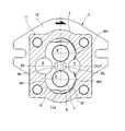
- FIG. 1 is a schematic view showing a gear pump according to a first embodiment of the present invention.
- Sectional drawing corresponded in FIG. 4 in the state equipped with the high voltage
- FIGS. 1-10 A first embodiment of the present invention is shown below with reference to FIGS.
- the gear pump according to the present embodiment mainly includes, as shown in FIG. 1, a body 11 having a gear storage chamber 11a inside, a front cover 12 for closing the gear storage chamber 11a of the body 11 from the front, and the body 11 A casing 1 formed by joining a rear cover 13 closing the gear storage chamber 11a from the rear, and an external gear pair housed and held in the first gear storage chamber 11a of the casing 1, that is, a drive gear 2 And the driven gear 3, the drive shaft 4 and the driven shaft 5 supporting the drive gear 2 and the driven gear 3, the side plate 6 contacting the side surfaces of the drive gear 2 and the driven gear 3, and the drive shaft 4.
- a bush 7 is a bearing portion disposed respectively, and a gasket 8 is disposed between the side plates 6 and the casing 1.
- the casing 1, the drive gear 2, the driven gear 3, the drive shaft 4, the driven shaft 5 and the bush 7 are all similar to those known as being used in this type of gear pump. Therefore, the detailed description is omitted.
- the side plates 6 are disposed at two places so as to be in contact with the side surfaces 2a and 3a of the drive gear 2 and the driven gear 3 as shown in FIG. 1, and the side surfaces 2a and 3a of the drive gear 2 and the driven gear 3 are provided. To seal each. As shown in FIGS. 2 and 3, of the outer peripheral edge of the side plate 6, the low-pressure side, ie, the inlet X side and the high-pressure side, ie, the outlet Y side, have edges corresponding to the inner surface of the gear storage chamber 11a. I am The sliding surface 6a of the side plate is processed to reduce the friction generated between the side plate 6 and the drive gear 2 or the driven gear 3.
- the part corresponding to the meshing part of the said drive gearwheel 2 and the driven gearwheel 3 in this side plate 6 is comprised as follows. At portions closer to the suction port X and the discharge port Y, a total of two communication holes 6x and 6y for guiding the hydraulic fluid to the side opposite to the gears 2 and 3 beyond the side plate 6 are provided in total.
- the portion between the communication holes 6x and 6y has a flat plate shape to mesh the gears 2 and 3 in order to seal that the hydraulic fluid leaks from the high pressure side (discharge port Y side) to the low pressure side (suction port X).
- the plane portions 6p and 6q are opposed to the portion.
- the flat portion 6p on the sliding surface 6a side is configured to be larger than the flat portion 6q on the non-sliding surface 6b side.
- a bottomed groove 6z opened on the non-sliding surface 6b side is continued at the end edge of the communication hole 6x on the low pressure side opposite to the suction port X. It is set up. That is, in the portion where the bottomed groove 6z is provided, the surface on the sliding surface 6a side is continuous with the surface of the adjacent portion to form the flat portion 6p, while the surface on the non-sliding surface 6b side
- the surface is a groove bottom of the bottomed groove 6z and does not constitute the flat portion 6q.
- the width d1 of the flat portion 6p on the sliding surface 6a side is equal to that of the flat portion 6q on the non-sliding surface 6b side. It is larger than the width dimension d2.
- the area of the flat portion 6p on the sliding surface 6a side is larger than the flat portion 6q on the non-sliding surface 6b side by the bottom surface integral of the bottomed groove 6z.
- the area of the plane portion 6 q facing the location corresponding to the meshing location of the drive gear 2 and the driven gear 3 is the side plate 6. It is smaller than the area of the flat portion 6p when incorporated in the correct direction. Therefore, during operation of the gear pump, the amount of hydraulic fluid leaking from the discharge port Y to the suction port X increases, and the flow efficiency decreases.
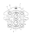
- FIGS. 4 and 5 a second embodiment of the present invention is shown below with reference to FIGS. 4 and 5.
- the gear pump according to the present embodiment has the same configuration as that according to the first embodiment described above, except for the shape of the side plate as described below.
- the parts corresponding to those in the first embodiment are given the same names and reference numerals, and the detailed description is omitted.
- the side plates of the gear pump according to the present embodiment are disposed at two places so as to be in contact with the side surfaces 2a and 3a of the drive gear 2 and the driven gear 3, and the side surfaces 2a and 3a of the drive gear 2 and the driven gear 3 are used. Each is for sealing.
- an end edge 6e on the low pressure side ie, the suction port X side
- the edge 6 f on the high pressure side that is, the discharge port Y side has a shape as shown below.
- an abutting portion 6f1 that abuts on the gear storage chamber 11a is provided.
- the end edge 6f is configured to face the inner surface of the gear storage chamber 11a with a slight gap only by the contact portion 6f1 and to be largely separated from the inner surface of the gear storage chamber 11a in other places.
- the circumferential length of the contact 6f portion is set shorter than one pitch of the gears 2 and 3.
- the side plate 6 When the side plate 6 is correctly mounted, as shown in FIG. 4, the side plate 6 is pressed toward the suction port X by a force derived from the hydraulic pressure, and the edge 6e on the suction port X side is It strikes against the inner surface of the gear storage chamber 11a, and prevents the hydraulic fluid from leaking to the suction port X side beyond the side plate 6.
- the edge 6f located on the suction port X side is only the contact portion 6f1.
- the inner surface of the gear storage chamber 11a is hit.
- the contact portion 6f1 is shorter than one pitch of the gear as described above. Therefore, when the space between the teeth of the gears 2 and 3 reaches the position facing the contact portion 6f1, the space filled with the high-pressure hydraulic fluid passes through the space between the teeth and the teeth. It communicates with the low pressure side (the suction port X side). This reduces the flow efficiency during operation of the gear pump.
- the present invention is not limited to the embodiments described above.
- the configurations according to the features of the first and second embodiments described above may be simultaneously applied to the same side plate. That is, while providing a bottomed groove opened to the non-sliding surface of the side plate, and providing a contact portion to be in contact with the gear storage chamber at a part of the high pressure side edge, the circumferential length of the contact portion A mode may be adopted in which the height is set shorter than one pitch of the gear.
- worn the side plate upside down via the fall of flow rate efficiency is not restricted to what concerns on 1st embodiment mentioned above.
- the area of the flat portion facing the location corresponding to the meshing location of the drive gear and the driven gear has the side plate incorporated in the correct direction.
- the configuration for promoting the discovery of reverse installation of the high-pressure side and the low-pressure side of the side plate via the decrease in the flow efficiency is not limited to that according to the second embodiment described above.
- the configuration according to the second embodiment as described above, when the high-pressure side and the low-pressure side of the side plate are mounted reversely, the length of the contact portion of the edge to be disposed on the high-pressure side If this edge and the contact part are disposed on the low pressure side by making the pitch shorter than one pitch of the gear, the flow efficiency will be greatly reduced, so this is also a simple configuration and effectively the side plate A difference in flow efficiency with orientation can be produced.
Landscapes
- Engineering & Computer Science (AREA)
- Mechanical Engineering (AREA)
- General Engineering & Computer Science (AREA)
- Chemical & Material Sciences (AREA)
- Combustion & Propulsion (AREA)
- Rotary Pumps (AREA)
- Hydraulic Motors (AREA)
- Physics & Mathematics (AREA)
- Fluid Mechanics (AREA)
Abstract
Priority Applications (7)
| Application Number | Priority Date | Filing Date | Title |
|---|---|---|---|
| CN201780094501.2A CN111051697B (zh) | 2017-10-13 | 2017-10-13 | 齿轮泵或马达 |
| JP2019547885A JP6954366B2 (ja) | 2017-10-13 | 2017-10-13 | 歯車ポンプ又はモータ |
| KR1020207005944A KR102231824B1 (ko) | 2017-10-13 | 2017-10-13 | 기어 펌프 또는 모터 |
| US16/651,351 US10975863B2 (en) | 2017-10-13 | 2017-10-13 | Gear pump or motor with features for determining if assembled correctly |
| PCT/JP2017/037223 WO2019073602A1 (fr) | 2017-10-13 | 2017-10-13 | Pompe à engrenages ou moteur |
| EP17928684.4A EP3696414A1 (fr) | 2017-10-13 | 2017-10-13 | Pompe à engrenages ou moteur |
| CN202111191974.9A CN113847237B (zh) | 2017-10-13 | 2017-10-13 | 齿轮泵或马达 |
Applications Claiming Priority (1)
| Application Number | Priority Date | Filing Date | Title |
|---|---|---|---|
| PCT/JP2017/037223 WO2019073602A1 (fr) | 2017-10-13 | 2017-10-13 | Pompe à engrenages ou moteur |
Publications (1)
| Publication Number | Publication Date |
|---|---|
| WO2019073602A1 true WO2019073602A1 (fr) | 2019-04-18 |
Family
ID=66100483
Family Applications (1)
| Application Number | Title | Priority Date | Filing Date |
|---|---|---|---|
| PCT/JP2017/037223 Ceased WO2019073602A1 (fr) | 2017-10-13 | 2017-10-13 | Pompe à engrenages ou moteur |
Country Status (6)
| Country | Link |
|---|---|
| US (1) | US10975863B2 (fr) |
| EP (1) | EP3696414A1 (fr) |
| JP (1) | JP6954366B2 (fr) |
| KR (1) | KR102231824B1 (fr) |
| CN (2) | CN113847237B (fr) |
| WO (1) | WO2019073602A1 (fr) |
Families Citing this family (1)
| Publication number | Priority date | Publication date | Assignee | Title |
|---|---|---|---|---|
| CN112709692B (zh) * | 2020-12-29 | 2023-02-17 | 西安精密机械研究所 | 一种提高海水泵容积效率的轴向补偿机构以及海水泵 |
Citations (6)
| Publication number | Priority date | Publication date | Assignee | Title |
|---|---|---|---|---|
| JPS504883B1 (fr) * | 1966-08-15 | 1975-02-25 | ||
| US4311445A (en) * | 1979-10-30 | 1982-01-19 | Tyrone Hydraulics, Inc. | Contaminant resistant gear pumps and motors with wear inserts |
| JPS6385275A (ja) * | 1986-09-26 | 1988-04-15 | Kayaba Ind Co Ltd | ギヤポンプ |
| JPS647257U (fr) * | 1987-06-29 | 1989-01-17 | ||
| JP2007239621A (ja) | 2006-03-09 | 2007-09-20 | Toyota Industries Corp | ギヤポンプ |
| JP2017150387A (ja) * | 2016-02-24 | 2017-08-31 | ダイキン工業株式会社 | 歯車ポンプ又は歯車モータ |
Family Cites Families (11)
| Publication number | Priority date | Publication date | Assignee | Title |
|---|---|---|---|---|
| US4087216A (en) * | 1976-10-05 | 1978-05-02 | Permco, Inc. | Flow diverter pressure plate |
| JPS60147786U (ja) * | 1984-03-13 | 1985-10-01 | 小松ゼノア株式会社 | 歯車式油圧回転装置 |
| JP2787706B2 (ja) * | 1989-04-30 | 1998-08-20 | 株式会社島津製作所 | 歯車ポンプ |
| CN201335011Y (zh) * | 2008-12-18 | 2009-10-28 | 四川长江液压件有限责任公司 | 用于高压齿轮泵的浮动侧板 |
| CN101571123B (zh) * | 2009-06-05 | 2013-04-03 | 合肥长源液压股份有限公司 | 等压力全平衡式浮动侧板 |
| CN202441590U (zh) * | 2012-02-21 | 2012-09-19 | 徐州尚品通合精密机械有限公司 | 一种高压齿轮泵 |
| WO2014199489A1 (fr) * | 2013-06-13 | 2014-12-18 | 株式会社 島津製作所 | Pompe ou moteur à engrenages |
| CN104564658A (zh) * | 2013-10-10 | 2015-04-29 | 宁夏琪凯节能设备有限公司 | 一种节能型外啮合齿轮泵 |
| CN103912485B (zh) * | 2014-04-29 | 2016-07-13 | 郑州机械研究所 | 一种结构紧凑型大流量低脉动齿轮泵 |
| JP6226067B2 (ja) * | 2014-05-28 | 2017-11-08 | 株式会社島津製作所 | 歯車ポンプ又はモータ |
| CN106989011A (zh) * | 2017-05-11 | 2017-07-28 | 常州大学 | 外啮合球齿泵 |
-
2017
- 2017-10-13 CN CN202111191974.9A patent/CN113847237B/zh active Active
- 2017-10-13 CN CN201780094501.2A patent/CN111051697B/zh active Active
- 2017-10-13 JP JP2019547885A patent/JP6954366B2/ja active Active
- 2017-10-13 KR KR1020207005944A patent/KR102231824B1/ko active Active
- 2017-10-13 EP EP17928684.4A patent/EP3696414A1/fr not_active Withdrawn
- 2017-10-13 US US16/651,351 patent/US10975863B2/en active Active
- 2017-10-13 WO PCT/JP2017/037223 patent/WO2019073602A1/fr not_active Ceased
Patent Citations (6)
| Publication number | Priority date | Publication date | Assignee | Title |
|---|---|---|---|---|
| JPS504883B1 (fr) * | 1966-08-15 | 1975-02-25 | ||
| US4311445A (en) * | 1979-10-30 | 1982-01-19 | Tyrone Hydraulics, Inc. | Contaminant resistant gear pumps and motors with wear inserts |
| JPS6385275A (ja) * | 1986-09-26 | 1988-04-15 | Kayaba Ind Co Ltd | ギヤポンプ |
| JPS647257U (fr) * | 1987-06-29 | 1989-01-17 | ||
| JP2007239621A (ja) | 2006-03-09 | 2007-09-20 | Toyota Industries Corp | ギヤポンプ |
| JP2017150387A (ja) * | 2016-02-24 | 2017-08-31 | ダイキン工業株式会社 | 歯車ポンプ又は歯車モータ |
Also Published As
| Publication number | Publication date |
|---|---|
| US10975863B2 (en) | 2021-04-13 |
| CN111051697B (zh) | 2021-12-07 |
| KR102231824B1 (ko) | 2021-03-24 |
| CN113847237B (zh) | 2023-05-30 |
| CN111051697A (zh) | 2020-04-21 |
| JPWO2019073602A1 (ja) | 2020-04-02 |
| KR20200037327A (ko) | 2020-04-08 |
| CN113847237A (zh) | 2021-12-28 |
| EP3696414A1 (fr) | 2020-08-19 |
| US20200232326A1 (en) | 2020-07-23 |
| JP6954366B2 (ja) | 2021-10-27 |
Similar Documents
| Publication | Publication Date | Title |
|---|---|---|
| CN103362816B (zh) | 旋转式压缩机 | |
| CN107835902A (zh) | 涡旋式压缩机 | |
| US20130164164A1 (en) | Scroll compressor | |
| WO2019073602A1 (fr) | Pompe à engrenages ou moteur | |
| JP2016196842A (ja) | 歯車ポンプ又はモータ | |
| JP6252802B2 (ja) | 歯車ポンプ又はモータ | |
| JPWO2013186839A1 (ja) | 歯車ポンプ又はモータ | |
| JP4211871B2 (ja) | スクリュー圧縮機 | |
| JP4400689B2 (ja) | スクリュー圧縮機 | |
| JP2015105594A (ja) | スクロール圧縮機 | |
| JP6422280B2 (ja) | 内接歯車ポンプ | |
| JP6395155B2 (ja) | 外接ギヤポンプ | |
| JP4721319B2 (ja) | 水用内接歯車ポンプ | |
| JP2006009576A (ja) | スクロール圧縮機 | |
| JP2013170552A (ja) | ギヤポンプ及びそれに用いられるシール部材 | |
| JP6631106B2 (ja) | 歯車ポンプ又は歯車モータ | |
| JP2005344538A (ja) | 歯車ポンプ | |
| JP2010106706A (ja) | 密閉型電動圧縮機 | |
| KR20180125665A (ko) | 스크롤 압축기 | |
| WO2020183661A1 (fr) | Pompe à engrenages et moteur à engrenages | |
| JP2016205290A (ja) | 内接歯車ポンプ | |
| JP2014109249A (ja) | 歯車ポンプまたはモータ | |
| KR101964800B1 (ko) | 스크롤 압축기 | |
| JP2014005731A (ja) | スクロール圧縮機 | |
| JPWO2016024519A1 (ja) | 液圧装置 |
Legal Events
| Date | Code | Title | Description |
|---|---|---|---|
| 121 | Ep: the epo has been informed by wipo that ep was designated in this application |
Ref document number: 17928684 Country of ref document: EP Kind code of ref document: A1 |
|
| ENP | Entry into the national phase |
Ref document number: 2019547885 Country of ref document: JP Kind code of ref document: A |
|
| ENP | Entry into the national phase |
Ref document number: 20207005944 Country of ref document: KR Kind code of ref document: A |
|
| NENP | Non-entry into the national phase |
Ref country code: DE |
|
| ENP | Entry into the national phase |
Ref document number: 2017928684 Country of ref document: EP Effective date: 20200513 |