WO2019073605A1 - Compresseur à spirale - Google Patents
Compresseur à spirale Download PDFInfo
- Publication number
- WO2019073605A1 WO2019073605A1 PCT/JP2017/037229 JP2017037229W WO2019073605A1 WO 2019073605 A1 WO2019073605 A1 WO 2019073605A1 JP 2017037229 W JP2017037229 W JP 2017037229W WO 2019073605 A1 WO2019073605 A1 WO 2019073605A1
- Authority
- WO
- WIPO (PCT)
- Prior art keywords
- balancer
- slider
- main shaft
- centrifugal force
- scroll compressor
- Prior art date
- Legal status (The legal status is an assumption and is not a legal conclusion. Google has not performed a legal analysis and makes no representation as to the accuracy of the status listed.)
- Ceased
Links
Images







Classifications
-
- F—MECHANICAL ENGINEERING; LIGHTING; HEATING; WEAPONS; BLASTING
- F04—POSITIVE - DISPLACEMENT MACHINES FOR LIQUIDS; PUMPS FOR LIQUIDS OR ELASTIC FLUIDS
- F04C—ROTARY-PISTON, OR OSCILLATING-PISTON, POSITIVE-DISPLACEMENT MACHINES FOR LIQUIDS; ROTARY-PISTON, OR OSCILLATING-PISTON, POSITIVE-DISPLACEMENT PUMPS
- F04C18/00—Rotary-piston pumps specially adapted for elastic fluids
- F04C18/02—Rotary-piston pumps specially adapted for elastic fluids of arcuate-engagement type, i.e. with circular translatory movement of co-operating members, each member having the same number of teeth or tooth-equivalents
Definitions
- the present invention relates to a scroll-type compressor used for refrigeration or air conditioning applications.
- variable radius crank mechanisms In the scroll type compressor, in order to reduce the leakage loss, the side clearance between the scrolls is minimized by bringing the sides of the scroll of the swing scroll and the scroll of the fixed scroll into contact with each other.
- Variable radius crank mechanisms are known.
- the component force of the gas load acting on the rocking scroll by compression is used as the pressing force of the side surface of the spiral body so that the centrifugal force acting on the parts moving rocking is not supported by the spiral side surface It has been proposed to use the following (see, for example, Patent Document 1).
- the compressor disclosed in Patent Document 1 balances (cancels out) the centrifugal force of a rocking moving part (such as a rocking scroll, a bush, or a slider) on a mechanical part (for example, a bush or a slider) whose crank radius is variable.
- a rocking moving part such as a rocking scroll, a bush, or a slider
- a mechanical part for example, a bush or a slider
- variable radius crank mechanism integrated with a balance weight that cancels the centrifugal force of the swinging motion parts
- pressing force there are some which use an elastic body such as a spring to generate it.
- a so-called over-canceling type variable radius crank mechanism has been proposed in which a balance weight integral with the variable radius crank mechanism is provided to generate a larger canceling (centrifugal) force than the swinging motion parts group (for example, , Patent Document 2).
- the cancellation rate exceeds 100%
- pressing of the side of the scroll is performed by the component force of the gas load or the spring force at low speed operation.
- the centrifugal force due to the portion exceeding the cancellation rate 100% at high speed operation becomes larger than the side pressing force by the gas force or the spring force, the side pressing of the spiral body is not performed.
- the supporting ratio of the centrifugal force acting on the rocking component between the spiral side surface and the rocking bearing depends on the cancellation rate .
- the cancellation rate is 0% (without the balance weight)
- the support by the spiral side surface is 100%.
- the cancellation rate is 100%, or when the cancellation rate exceeds 100% and the variable radius crank mechanism is provided with a stopper in the cancellation direction
- the support by the rocking bearing is 100%.
- the centrifugal force acting on the swinging component between the spiral side surface and the rocking bearing is proportionally supported in accordance with the cancellation rate.
- the support ratio of the spiral side surface is 30%
- the support ratio of the rocking bearing is 70%. This support ratio is constant regardless of the rotational speed.
- a relatively low cancellation rate close to 0% is selected to ensure contact between the side surfaces of the spiral bodies and to suppress the increase in leakage loss in the low speed region, the support of centrifugal force on the spiral side surfaces is high.
- the load resulting from the centrifugal force during operation concentrates on the side of the scroll and the main bearing.
- the cancellation rate to reduce the pressing load on the side of the scroll during high-speed operation, or set the cancellation rate to a high value of around 100% in order to reduce noise without bringing the sides of the scroll into contact with each other during medium to high speed operation.
- the load caused by the centrifugal force at the time of high speed operation is concentrated on the rocking bearing.
- the intermediate cancellation ratio is set so that the load supporting ratio by centrifugal force is not biased to either the swing bearing or the spiral side during high speed operation, the spiral side seal in the low speed operation region as described above. Characteristics and noise reduction during medium to high speed operation can not be obtained sufficiently.
- the present invention has been made to solve the above-mentioned problems, and it achieves both dispersion support of centrifugal force at high speed operation, side sealability at low speed operation and quietness at medium to high speed operation. It is an object of the present invention to provide a scroll compressor that can be driven.
- the scroll compressor according to the present invention comprises a compression mechanism having a fixed scroll and a swing scroll that swings relative to the fixed scroll, a rotating main shaft, and a rotating force of the main shaft from the center of the main shaft.
- a variable radius crank mechanism that transmits the swinging scroll as a swinging force via a moving member having a variable speed, and a balancer that generates a centrifugal force opposite to a centrifugal force generated on the swinging component by rotation of the main shaft;
- a scroll compressor having a stopper portion connected to the main shaft, and a mechanism for displacing the balancer by a change in rotational speed of the main shaft, wherein the centrifugal force of the balancer is controlled by the stopper portion and the variable radius by the change in rotational speed of the main shaft
- the ratio supported by the moving member of the crank mechanism changes.
- the scroll compressor according to the present invention has the stopper portion connected to the main shaft and the mechanism in which the balancer is displaced by the change of the rotational speed of the main shaft, and the centrifugal force of the balancer is stopped by the change of the rotational speed of the main shaft.
- the ratio supported by the moving part and the moving member of the variable radius crank mechanism changes. Therefore, the scroll compressor can automatically change the indicated ratio of the spiral side surface of the centrifugal force of the rocking component and the rocking bearing depending on the rotational speed. For this reason, the centrifugal force acting on the rocking parts is supported 100% by the rocking bearing or spiral side at low speed rotation, and the load capacity of the rocking bearing and the spiral side at the high speed rotation range close to the upper limit rotation speed respectively. It can support by the ratio which considered the sliding characteristic. As a result, the scroll compressor can achieve characteristics such as centrifugal force dispersion support at high speed operation, side sealability at low speed operation, and quietness at medium to high speed operation.
- FIG. 1 is a schematic longitudinal sectional view of a scroll compressor having a general variable radius crank mechanism using a slider. It is a longitudinal cross-sectional view which shows the variable radius crank mechanism of FIG. It is a model top view which shows the variable radius crank mechanism of FIG. It is an exploded perspective view of a slider balancer part of a scroll compressor concerning Embodiment 1 of the present invention. It is a schematic diagram which shows the longitudinal cross-section of the slider balancer part of the scroll compressor which concerns on Embodiment 1 of this invention.
- FIG. 7 is a schematic cross-sectional view of the slider balancer portion taken along the line AA in FIG. FIG.
- FIG. 7 is a schematic cross-sectional view of the slider balancer portion taken along the line BB in FIG. It is a graph which shows the change pattern with respect to rotation speed [rps] of each bearing load and pressing force F [kgf] of the spiral side surface in the scroll compressor concerning Embodiment 1 of this invention. It is a graph which shows the change pattern with respect to rotation speed [rps] of the support ratio of the rocking bearing of the rocking part and the side surface of the spiral in the scroll compressor according to Embodiment 1 of the present invention. It is a graph which shows the pattern of the change with respect to rotation speed [rps] of each bearing load and pressing force F [kgf] of the spiral side surface in the scroll compressor using the conventional slider balancer.
- FIG. 14 is a cross-sectional view of the slider balancer portion of FIG. 13 taken along the line CC. Operation explanation showing changes in centrifugal force and reaction force acting on the slider balancer at each rotation speed from low speed operation (a) to high speed operation (e) of the scroll compressor according to Embodiment 2 of the present invention.
- FIG. 1 is a schematic longitudinal sectional view showing a structure of a scroll compressor 1 according to a first embodiment of the present invention.
- the scroll compressor 1 sucks and compresses a fluid such as a refrigerant, and discharges the fluid in a high temperature and high pressure state.
- the scroll compressor 1 includes a compression mechanism portion 2 for compressing a refrigerant, a motor 3 for driving the compression mechanism portion 2, and a closed container 21 for accommodating the compression mechanism portion 2 and the motor 3.
- a compression mechanism portion 2 for compressing a refrigerant
- a motor 3 for driving the compression mechanism portion 2
- a closed container 21 for accommodating the compression mechanism portion 2 and the motor 3.
- the closed container 21 constitutes an outer shell of the scroll compressor 1.
- the compression mechanism 2, the motor 3, and the main shaft 15 are accommodated.
- a suction pipe 23 communicating with the inside of the closed container 21 is connected to the side surface of the closed container 21.
- a discharge pipe 24 to which the refrigerant compressed by the compression mechanism 2 is discharged is connected to an upper portion of the closed container 21.
- lubricating oil 22 is stored at the bottom of the closed container 21.
- the compression mechanism 2 compresses a fluid (for example, a refrigerant) drawn into the closed container 21 from the suction pipe 23.
- the compression mechanism portion 2 has a fixed scroll 11 fixed to a frame 14 attached to the closed container 21 and a swing scroll 12 swinging (that is, revolving) relative to the fixed scroll 11. .
- the fixed scroll 11 can be configured to be fixed to the closed container 21 without being fixed to the frame 14.
- the fixed scroll 11 and the oscillating scroll 12 are combined such that the respective spiral teeth 114 and the spiral teeth 126 mesh with each other. Between the spiral teeth 114 and the spiral teeth 126, a compression chamber in which the refrigerant is compressed is formed.
- An Oldham ring 13 is provided between the rocking scroll 12 and the frame 14 to regulate the rotation of the rocking scroll 12 with respect to the fixed scroll 11.
- the Oldham ring 13 is disposed below the base plate portion 122 of the rocking scroll 12 and is used to block the rotational movement of the rocking scroll 12 during the rocking movement.
- the fixed scroll 11 compresses the refrigerant together with the oscillating scroll 12.
- the fixed scroll 11 is disposed to face the oscillating scroll 12.
- the fixed scroll 11 has a flat plate-shaped base plate portion 113, and spiral teeth 114 formed to project from the base plate portion 113 to the oscillating scroll 12 side.
- the spiral teeth 114 correspond to the “first spiral” in the present invention.
- the base plate portion 113 together with the spiral teeth 114, the oscillating scroll 12 and the frame 14, constitutes a compression chamber.
- the base plate portion 113 is fixed in the sealed container 21 so that the outer peripheral surface thereof faces the inner peripheral surface of the sealed container 21 and the outer side of the lower end surface of the base plate portion 113 faces the upper portion of the frame 14 It is done.
- a discharge port 111 for discharging the compressed refrigerant from the compression chamber is formed at a central portion of the base plate portion 113 so as to penetrate the base plate portion 113.
- a discharge valve 25 having a reed valve structure is provided at the outlet side of the discharge port 111.
- the discharge valve 25 closes the discharge port 111 if the pressure is smaller than a preset pressure and restricts the flow of the refrigerant from the compression chamber side to the discharge pipe 24. However, when the pressure exceeds the predetermined pressure, the discharge port 111 Open.
- the spiral teeth 114 together with the spiral teeth 126 of the oscillating scroll 12, compress the refrigerant. Further, the spiral teeth 114 together with the base plate portion 113 and the rocking scroll 12 form a compression chamber whose volume is changed by the rocking of the rocking scroll 12.
- the spiral teeth 114 have a horizontal cross section formed in a spiral shape.
- the oscillating scroll 12 compresses the refrigerant together with the fixed scroll 11.
- the spiral teeth 126 for compressing the refrigerant are formed together with the spiral teeth 114, and a compression chamber is formed between the fixed scroll 11 and the spiral teeth 126.
- the oscillating scroll 12 is disposed to face the fixed scroll 11.
- the rocking scroll 12 has a flat plate-shaped base plate portion 122 and spiral teeth 126 formed to project from the base plate portion 122 to the fixed scroll 11 side.
- the spiral teeth 126 correspond to the “second spiral” of the present invention.
- the base plate portion 122 together with the spiral teeth 126, the fixed scroll 11, and the frame 14, constitutes a compression chamber.
- the base plate portion 122 is a disk-shaped member, and swings in the frame 14 by rotation of the main shaft 15.
- an axial thrust load is supported by an overhang portion 141 installed as a separate member from the frame 14.
- a cylindrical boss portion 121 is formed at a central portion of a surface (a lower surface in FIG. 1) opposite to the surface on which the spiral teeth 126 are formed.
- the spiral teeth 126 compress the refrigerant together with the spiral teeth 114 of the fixed scroll 11.
- the spiral teeth 126 together with the base plate portion 122 and the fixed scroll 11 constitute a compression chamber.
- the spiral teeth 126 have a horizontal cross section formed in a spiral shape.
- the boss portion 121 has a function as a rocking bearing.
- the end portion of the main shaft 15 is connected to the boss portion 121.
- the variable radius crank mechanism 5 using the moving member 30 is adopted, and the moving member 30 is rotatably provided on the inner peripheral side of the boss portion 121.
- the motor 3 rotates the main shaft 15.
- the electric motor 3 has a stator 19 fixed to the inner peripheral wall of the sealed container 21 and a rotor 18 disposed on the inner peripheral side of the stator 19.
- the stator 19 is configured by attaching multi-phase windings to a laminated core.
- the rotor 18 has a permanent magnet (not shown) inside.
- a main shaft 15 for transmitting the rotational driving force of the motor 3 to the oscillating scroll 12 is fixed to the rotor 18. That is, when the stator 19 is energized, the rotor 18 is configured to rotate integrally with the main shaft 15.
- the motor 3 can change the number of rotations of the rotor 18 by inverter control or the like, for example.
- a second balancer 17 is provided below the rotor 18.
- the main shaft 15 transmits rotational drive force to the oscillating scroll 12.
- the upper portion of the main shaft 15 is rotatably supported by a main bearing 143 provided on the frame 14, and the lower portion of the main shaft 15 is rotatably supported by the auxiliary bearing 20.
- the sub bearing 20 is provided on the sub frame 28, and is configured of, for example, a ball bearing.
- An eccentric shaft portion 151 is provided at an upper end portion of the main shaft 15.
- the eccentric shaft portion 151 is eccentrically arranged in a predetermined eccentric direction with respect to the central axis of the main shaft 15.
- the eccentric shaft 151 is slidably inserted into the groove 31 of the moving member 30.
- the main shaft 15 is provided with a first balancer 16 that balances the swinging motion below the eccentric shaft 151 and above the rotor 18 of the motor 3.
- the first balancer 16 and the second balancer 17 are provided in order to offset the unbalance associated with the eccentricity due to the oscillating scroll 12, the moving member 30, and the oldham ring 13, and to balance the balance as a whole rotation system.
- an oil pump (not shown) for sucking up the lubricating oil 22 in the oil reservoir is provided at the lower end of the main shaft 15.
- an oil hole (not shown) is formed inside the main shaft 15 along the central axis direction of the main shaft 15. The lubricating oil 22 sucked up by an oil pump provided at the lower end of the main shaft 15 is supplied to each sliding portion through an oil hole formed in the main shaft 15.
- the relationship between the variable radius crank mechanism 5 and the slider balancer unit 301 will be described later.
- the gas refrigerant sucked into the sealed container 21 from the suction pipe 23 with the rocking motion of the rocking scroll 12 is taken into the compression chamber between the spiral teeth of the fixed scroll 11 and the rocking scroll 12 and compressed. Thereafter, the compressed refrigerant is discharged from the discharge port 111 provided on the fixed scroll 11 against the discharge valve 25 and discharged from the discharge pipe 24 to the circuit.
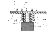
- FIG. 2 is a schematic longitudinal sectional view of a scroll compressor 1t having a general variable radius crank mechanism using a slider.
- FIG. 3 is a longitudinal sectional view showing the variable radius crank mechanism of FIG.
- FIG. 4 is a schematic plan view showing the variable radius crank mechanism of FIG.
- the variable radius crank mechanism 5t includes a moving member 30t disposed in a boss 121t of the oscillating scroll 12t, an eccentric shaft 151t provided on a main shaft 15t, and the like.
- the variable radius crank mechanism 5t makes the swing radius variable when swinging movement of the swing scroll 12t by the rotation of the main shaft 15t.
- the oscillating component is configured of the oscillating scroll 12 and the moving member 30 and the like.
- the pressing force on the side surface of the spiral means the force at which the spiral tooth 114 and the spiral tooth 126 press each other, and the pressure side reaction force on the spiral side acts on each of the spiral tooth 114 and the spiral tooth 126 as a result of pressing each other. Point to the reaction force.
- symbol of the structure corresponding to the various structures demonstrated by the scroll compressor 1 of Embodiment 1 the symbol t is attached
- the scroll compressor 1t which is a comparative example adopts a variable radius crank mechanism 5t using a moving member 30t.
- the moving member 30t has a cylindrical outer peripheral surface, and is rotatably and slidably disposed on the inner peripheral side of the boss portion 121t. Further, the moving member 30t is formed with an elongated hole shaped groove portion 301t into which the eccentric shaft portion 151t is slidably inserted in one direction in a reciprocating manner. In FIG. 4, the eccentric shaft 151t is eccentric to the right of the drawing with respect to the main shaft 15t.
- the groove 301t is formed to be inclined at an angle ⁇ with respect to the eccentric direction in a plan view (a cross section perpendicular to the central axes of the main shaft 15t and the eccentric shaft 151t). Further, on the eccentric shaft 151t sliding in the groove 301t, there is formed a slope P which is inclined at an angle ⁇ with respect to the eccentric direction in a plan view.
- the inclined surface P of the eccentric shaft 151t having an angle ⁇ with respect to the eccentric direction of the eccentric shaft 151t of the main shaft 15t drives the boss 121 of the oscillating scroll 12t via the moving member 30t.
- the variable radius crank mechanism 5t is configured.
- the circumferential gas load Fg ⁇ is supported by the slope P at the angle ⁇ , so a radial component force is generated, and the radial load acting on the oscillating motion parts group is ⁇ Fgr + Fc + Fg ⁇ ⁇ tan ⁇ Become. From the balance of the forces related to the swinging scroll 12t and the moving member 30t, a pressing force Fs to the spiral side surface equal to this is generated, and the spiral teeth 126t of the rocking scroll 12t press the spiral teeth 114t of the fixed scroll 11t to the spiral side Forced by force Fs. Thus, the generation of a gap between the spiral tooth 114t and the spiral tooth 126t can be suppressed.
- the pressing force Fs on the side surface of the spiral is determined by the force (centrifugal force Fc) dependent on the number of rotations of the main spindle 15t and the force independent of the number of rotations (gas load Fgr, Fg ⁇ , or spring force), and the square of the number of rotations
- the centrifugal force Fc that increases at the time of the high speed operation causes the pressing force Fs on the spiral side surface to become excessive.
- a variable radius crank mechanism which cancels the centrifugal force mentioned to the above-mentioned prior art is known.
- the centrifugal force canceling variable radius crank mechanism is provided with a balancer unit (a so-called slider balancer unit) which is integrated with the crank mechanism component and cancels the centrifugal force of the swinging component (generates a reverse centrifugal force).
- a balancer unit a so-called slider balancer unit
- the centrifugal force cancelable variable radius crank mechanism does not exert an excessive pressing force on the spiral side surface during high speed operation.
- the centrifugal force is applied to the rocking bearing between the rocking scroll generating the centrifugal force and the slider generating the canceling force (the centrifugal force in the reverse direction). It will be. That is, the centrifugal force generated in the rocking scroll is supported by the spiral side surface or the rocking bearing, and the supporting ratio depends on the cancel ratio which is the ratio of the canceling force to the centrifugal force.
- the canceling force is a force that cancels out the centrifugal force.
- FIG. 5 is an exploded perspective view of the slider balancer portion 301 of the scroll compressor 1 according to Embodiment 1 of the present invention.
- FIG. 6 is a schematic view showing a vertical cross section of the slider balancer portion 301 of the scroll compressor 1 according to Embodiment 1 of the present invention.
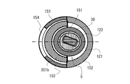
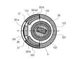
- FIG. 7 is a schematic sectional view taken along the line AA of the slider balancer portion 301 in FIG.
- FIG. 8 is a schematic sectional view taken along the line BB of the slider balancer portion 301 in FIG.
- the variable radius crank mechanism of the scroll compressor 1 which appropriately avoids that the pressing force against the spiral side surface at high speed operation and the swing bearing load at high speed operation become excessive using FIGS. 1 and 5 to 8. 5 and the slider balancer unit 301 will be described.
- variable radius crank mechanism 5 transmits the rotating force of the main shaft 15 as a force with which the oscillating scroll 12 oscillates via the moving member 30 whose distance from the center of the main axis is variable.
- the variable radius crank mechanism 5 defines a swing radius when the swing scroll 12 is caused to swing by the rotation of the main shaft 15.
- the variable radius crank mechanism 5 is provided at one end of the main shaft 15.
- the variable radius crank mechanism 5 has an eccentric shaft 151 eccentric to the central axis of the main shaft 15 and an eccentric shaft 151 inserted therein, and is provided on the inner peripheral side of a cylindrical boss 121 provided on the oscillating scroll 12. It comprises the moving member 30 provided rotatably and slidably.
- the main shaft 15 has, at the upper end portion on the compression mechanism 2 side, a cylindrical base shaft portion 150, a disk portion 155 protruding radially from the end of the base shaft portion 150, and a disk And an eccentric shaft portion 151 protruding from the portion 155 in the opposite direction to the base shaft portion 150.
- the eccentric shaft portion 151 is provided at one end of the main shaft 15, as shown in FIG. 6, and the central axis C2 of the eccentric shaft portion 151 is eccentric with respect to the central axis C1 of the main shaft 15.
- the central axis C2 of the eccentric shaft 151 is eccentric to the right in the drawing with respect to the central axis C1 of the main shaft 15.
- the main shaft 15 has a peripheral wall portion 156 which protrudes from the peripheral edge portion of the disk portion 155 in the same direction as the eccentric shaft portion 151.
- the peripheral wall portion 156 is provided at one end of the main shaft 15, has the same central axis C1 as the main shaft 15, and forms an inner peripheral wall facing the outer peripheral surface of the boss portion 121, as shown in FIG.
- the variable radius crank mechanism 5 is disposed inside the peripheral wall portion 156.
- the peripheral wall portion 156 is formed in a cylindrical shape, and a notch portion 154 is formed in a part of the wall portion on the opposite side to the side where the eccentric shaft portion 151 is eccentric.
- the notch portion 154 is formed in the circumferential direction and in the axial direction, and is notched from the end portion of the peripheral wall portion 156 on the side of the disk portion 155 to the end portion on the opposite side to the disk portion 155.
- the peripheral wall portion 156 refers to the wall portion of the semicircular portion on the side on which the eccentric shaft portion 151 is eccentric in plan view in the axial direction of the main shaft 15 as the offset balance portion 152 and opposite to the side on which the eccentric shaft portion 151 is eccentric.
- the wall portion of the side semicircular portion is referred to as a stopper portion 153.
- the main shaft 15 is provided from both ends of the counterbalance portion 152 constituting the wall portion of the semicircular portion on the side where the eccentric shaft 151 is eccentric, and both ends of the counterbalance portion 152 in the circumferential direction.
- a pair of stopper portions 153 that constitute extended wall portions.
- the stopper portion 153 is connected to the main shaft 15.
- the stopper portion 153 is a cylindrical peripheral wall portion which is formed at one end of the main shaft 15 and in which the variable radius crank mechanism 5 is disposed.
- the counterbalance portion 152 is provided at an end of the main shaft 15, and generates a centrifugal force in a direction opposite to a centrifugal force generated in a slider balancer 301 described later.
- the thickness of the counterbalance portion 152 is larger than the thickness of the pair of stopper portions 153, and the stopper portion 153 and the counterbalance portion 152 are integrally formed. Therefore, in the peripheral wall portion 156, the inner peripheral wall of the stopper portion 153 is recessed compared to the inner peripheral wall of the counterbalance portion 152, and the inner peripheral wall of the peripheral wall portion 156 extends from the stopper portion 153 to the counterbalance portion 152 It is formed.
- the circumferential lengths of the stopper portions 153 located at both ends of the counterbalance portion 152 are desirably equal, but may be different.
- a notch portion 154 is formed between the pair of stopper portions 153.
- the outer peripheral wall of the stopper portion 153 and the outer peripheral wall of the counterbalance portion 152 are formed flush with each other.
- the moving member 30 is a member whose distance from the center of the main shaft 15 changes, and is interposed between the boss 121 and the eccentric shaft 151 to determine the swing radius of the swing scroll 12.
- the moving member 30 is, for example, a slider.
- the moving member 30 has a cylindrical outer peripheral surface, and is provided rotatably and slidably on the inner peripheral side of the boss portion 121. Further, the moving member 30 is formed with an elongated hole shaped groove portion 31 into which the eccentric shaft portion 151 is inserted slidably in one direction.
- the moving member 30 is provided on a flat substrate portion 35. In FIG.
- the moving member 30 and the substrate unit 35 are integrally formed, but for example, the moving member 30 and the substrate unit 35 are separately formed and a circular opening formed in the substrate unit 35.
- the moving member 30 may be inserted into the The substrate portion 35 is extended in the direction opposite to the eccentric direction of the eccentric shaft portion 151 with respect to the main shaft 15, and the non-supporting slider balancer portion 301a is provided at the end in the extending direction.
- the eccentric shaft portion 151 of the main shaft 15 is inserted into the moving member 30, and the substrate portion 35 is disposed on the disk portion 155.
- the moving member 30, the base plate portion 35, and the non-supporting slider balancer portion 301 a are accommodated in a space surrounded by the peripheral wall portion 156 of the main shaft 15.
- the non-supporting slider balancer portion 301a is a weight and cancels the centrifugal force generated in the rocking scroll 12 and other rocking parts.
- the non-supporting slider balancer unit 301 a is connected to the moving member 30 via the substrate unit 35.
- the non-supporting slider balancer portion 301a has an outer peripheral wall formed in an arc shape, and an inner wall surface portion 301a1 facing the moving member 30 is formed in a planar shape.
- the non-supporting slider balancer portion 301 a has a length in the axial direction of the main shaft 15 shorter than a length of the peripheral wall portion 156 of the main shaft 15 and a length in the circumferential direction shorter than a length of the notch portion 154 of the main shaft 15.
- the non-supporting slider balancer portion 301a and the substrate portion 35 correspond to the "first balance weight” in the present invention.
- the non-supporting slider balancer portion 301a corresponds to the "weight main body portion" of the present invention.
- the half support slider balancer portion 301 b is a weight and cancels the centrifugal force generated in the rocking scroll 12 and other rocking parts.
- the semi-supporting slider balancer portion 301 b is formed in a semicircular arc shape.
- the semi-supporting slider balancer portion 301 b is disposed on the substrate portion 35.
- a notch 36 cut in an arc shape in a horizontal cross section is formed in a wall portion of a portion facing the non-supporting slider balancer portion 301a.
- the non-supporting slider balancer portion 301 a and the elastic member 26 are disposed in the bow-shaped cutout portion 36.
- the respective side surface portions 37 in the circumferential direction of the semi-supporting slider balancer portion 301 b constituting the notch portion 36 constitute a virtual identical plane.
- the axial length of the semi-supporting slider balancer portion 301b is desirably equal to the length of the peripheral wall portion 156 in a state of being disposed on the substrate portion 35.
- the semi-supporting slider balancer portion 301 b is slidably disposed between the boss portion 121 and the non-supporting slider balancer portion 301 a.
- the semi-support slider balancer portion 301 b corresponds to the “second balance weight” in the present invention.
- the slider balancer portion 301 includes two balance weights of the non-supporting slider balancer portion 301 a and the semi-supporting slider balancer portion 301 b which are disposed inside the peripheral wall portion 156 and whose mutual positions are variable. That is, the non-supporting slider balancer unit 301 a and the semi-supporting slider balancer unit 301 b constitute the slider balancer unit 301.
- the slider balancer unit 301 generates a centrifugal force that is reverse to the centrifugal force generated in the swinging part by the rotation of the main shaft 15. In addition, the slider balancer unit 301 generates a centrifugal force that exceeds the centrifugal force generated in the swinging component.
- the non-supporting slider balancer portion 301a and the semi-supporting slider balancer portion 301b correspond to the "two balance weights" of the present invention, and the outer peripheral side of the boss 121 in the direction of the notch 154 in the peripheral wall 156 Is located in That is, the non-supporting slider balancer portion 301 a and the semi-supporting slider balancer portion 301 b are disposed inside the peripheral wall portion 156 and disposed at a position facing the variable radius crank mechanism 5. These two balance weights cancel the centrifugal force generated in the rocking scroll 12 and other rocking parts.
- the slider balancer portion 301 can suppress the spiral tooth 114 from being pressed against the spiral tooth 126, and can suppress the abrasion with the moving member 30 and the eccentric shaft portion 151. Further, the slider balancer portion 301 can suppress the wear of the main bearing 143 and the sub bearing 20. Furthermore, the slider balancer portion 301 is positioned closer to the unbalanced barycenter of the swinging part as compared to the first balancer 16 and the second balancer 17. Thereby, the weight of the 1st balancer 16 and the 2nd balancer 17 can be reduced.
- the unbalance amount in the canceling direction of the non-supporting slider balancer portion 301a and the semi-supporting slider balancer portion 301b is a so-called over-cancellation that exceeds the unbalance amount of the swinging parts.
- the offset balance portion 152 of the peripheral wall portion 156 generates a load that balances with the amount of cancellation for the overrun.
- An elastic member 26 is disposed between the nonsupporting slider balancer portion 301a and the semisupporting slider balancer portion 301b as a mechanism for displacing the slider balancer portion 301.
- the slider balancer unit 301 corresponds to the “balancer” in the present invention.
- the elastic member 26 supports the load generated by the centrifugal force acting on the semi-supporting slider balancer portion 301 b by the rotation of the main shaft 15.
- the elastic member 26 is a mechanism in which the slider balancer portion 301 is displaced by a change in the rotational speed of the main shaft 15.
- the elastic member 26 is formed in a flat plate shape, and is disposed between the side surface portion 37 of the semi-supporting slider balancer portion 301 b and the inner wall surface portion 301 a 1 of the non-supporting slider balancer portion 301 a. Both ends of the elastic member 26 face the side surface portion 37, and on the opposite side to the side facing the side surface portion 37, the center faces the inner wall surface portion 301a1.
- the elastic member 26 has a structure in which a second moment of area and a support span are set so as to operate within a relatively narrow displacement range on the premise of the longitudinal elastic modulus of a general spring material. Also, since the displacement amount of the elastic member 26 fluctuates when the support cancel force changes due to the change of the rotational speed of the main shaft 15, the elastic member 26 does not lead to fatigue in normal use. . Therefore, the elastic member 26 does not need to use a special material to suppress stress assuming fatigue, but the shape of the detail is set in consideration of the minute movement of the support position at the time of deformation and the fretting associated therewith. There is a need.
- the semi-supporting slider balancer portion 301 b when the number of revolutions of the main shaft 15 is less than the threshold (for example, less than 90 rpm), the semi-supporting slider balancer portion 301 b is in contact with the elastic member 26.
- the centrifugal force in the cancel direction acting on the half-support slider balancer portion 301 b acts on the non-support slider balancer portion 301 a via the elastic member 26.
- the semi-supporting slider balancer portion 301 b and the non-supporting slider balancer portion 301 a have the same configuration as the integrally configured overcanceling slider, Component centrifugal force is offset.
- the spiral side surface is pressed by a component force corresponding to the slider angle of the gas load.
- the centrifugal force in the cancel direction acting on the non-supporting slider balancer portion 301a from the semi-supporting slider balancer portion 301b via the elastic member 26 increases.
- the centrifugal force of the half-support slider balancer portion 301b increases, the amount of movement of the half-support slider balancer portion 301b in the anti-eccentric (cancel) direction increases due to the deformation of the elastic member 26.
- a threshold for example, 90 rpm
- the semi-supporting slider balancer portion 301 b is supported by the stopper portion 153.
- the semi-supported slider balancer portion 301 b is supported by being in contact with the non-supported slider balancer portion 301 a and the stopper portion 153, the movement of the semi-supported slider balancer portion 301 b is restricted by the stopper portion 153. Therefore, even if the rotational speed of the main shaft 15 is further increased and the cancel force of the half support slider balancer portion 301b is increased, the deformation amount of the elastic member 26 is constant. The cancellation force transmitted to the non-supporting slider balancer portion 301a also becomes constant.
- the cancellation ratio is a ratio at which the slider balancer unit 301 cancels the centrifugal force of the swinging component.
- the scroll compressor 1 supports the centrifugal force of the slider balancer portion 301 only by either the stopper portion 153 or the moving member 30 when the rotation of the main shaft 15 is low.
- the scroll compressor 1 changes the centrifugal force of the slider balancer portion 301 so that the stopper portion 153 and the moving member 30 support the centrifugal force.
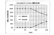
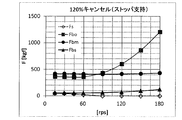
- FIG. 9 is a graph showing a pattern of changes with respect to the rotational speed [rps] of each bearing load and pressing force F [kgf] of the spiral side surface in the scroll compressor 1 according to Embodiment 1 of the present invention.
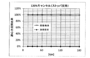
- FIG. 10 is a graph showing a change pattern of the centrifugal force of the swinging component in the scroll compressor 1 according to Embodiment 1 of the present invention with respect to the rotational speed [rps] of the support ratio between the swing bearing and the spiral side surface.
- An example of the cancellation characteristic of the scroll compressor 1 which concerns on Embodiment 1 of this invention is shown using FIG.9 and FIG.10. Note that FIG.
- FIG. 10 shows changes in the pressing force Fs on the spiral side surface, the swing bearing load Fbo, the main bearing load Fbm, and the auxiliary bearing load Fbs with the horizontal axis as the number of rotations of the main shaft 15. Moreover, FIG. 10 makes a horizontal axis the rotation speed of the main axis
- the ratio of the unbalanced amount of the semi-support slider balancer portion 301b to the unbalanced amount of the swinging parts is 70%, and the ratio of the unbalanced amount of the non-supported slider balancer portion 301a is 50. %
- the semi-supporting slider balancer portion 301b contacts the stopper portion 153 at an overcancellation of 120% of the total unbalance amount by the semi-supporting slider balancer portion 301b and the non-supporting slider balancer portion 301a and at a rotational speed of 90 rps or more. It is set as.
- the support ratio of the centrifugal force changes at 100% of the rocking bearing and 0% of the spiral side surface until 90 rps when the semi-supported slider balancer portion 301b starts contacting the stopper portion 153. Then, after 90 rps when the semi-supporting slider balancer portion 301b starts to contact the stopper portion 153, the support ratio on the rocking bearing side decreases, and the support ratio on the spiral side surface increases accordingly.
- the pressing force Fs on the side surface of the spiral depends on the component force of the gas load according to the slider angle up to 90 rps, but gradually decreases with an increase of over 20%. , 90 rps once the pressing force becomes zero.
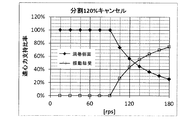
- FIG. 11 is a graph showing a pattern of change with respect to the rotational speed [rps] of each bearing load and pressing force F [kgf] on the spiral side surface in the scroll compressor using the conventional slider balancer.
- FIG. 12 is a graph showing a change pattern of the centrifugal force of the swinging component in the scroll compressor using the conventional slider balancer and the rotational ratio [rps] of the support ratio between the swing bearing and the spiral side surface.
- FIG. 11 and FIG. 12 are used to show the characteristics of the scroll compressor using the conventional slider balancer.
- FIGS. 11 and 12 show the characteristics of the conventional scroll compressor in the case of a slider balancer having a cancellation rate of 120%.
- the side pressing force is 90 rps or later where the cancel force of 20% over-cancellation balances the slider component of the gas load.
- the setting is 0 (noncontact).
- Conventional scroll compressors do not have a "semi-supporting" structure in which the slider balancer portion is supported across the shaft side and the slider side at high speed. Therefore, in the conventional scroll compressor, as shown in FIG. 12, the centrifugal force supporting ratio is 100% for the rocking bearing and 0% for the spiral side even after 90 rps when "non-contact". For this reason, in the conventional scroll compressor, the rocking bearing load Fbo rapidly increases as shown in FIG.
- the scroll compressor 1 has the stopper portion 153 connected to the main shaft 15 and the mechanism in which the slider balancer portion 301 is displaced by the change of the rotation speed of the main shaft 15.
- the ratio of supporting the centrifugal force of the slider balancer 301 by the stopper 153 and the moving member 30 of the variable radius crank mechanism changes. Therefore, the scroll compressor 1 can automatically change the instruction ratio of the spiral side surface of the centrifugal force of the rocking component and the rocking bearing depending on the rotational speed.
- the centrifugal force acting on the rocking parts is 100% supported by the rocking bearing or spiral side at low speed rotation below the threshold, and each of the rocking bearings in the high speed rotation area above the threshold close to the upper limit rotational speed It can be supported at a ratio that takes into consideration the load capacity and the sliding characteristics of the spiral side surface.
- the scroll compressor 1 can balance characteristics such as centrifugal force dispersion support at high speed operation, side sealability at low speed operation, and quietness at medium to high speed operation. Therefore, the scroll compressor 1 can ensure the reliability up to the high rotation speed range, and can be a compressor having a wide capacity range.
- the scroll compressor 1 supports only the centrifugal force of the slider balancer portion 301 by either the stopper portion 153 or the moving member 30, and the rotational speed of the main shaft 15 increases.
- the centrifugal force of the portion 301 is changed so that the stopper portion 153 and the moving member 30 support. Therefore, the scroll compressor 1 can automatically change the instruction ratio of the spiral side surface of the centrifugal force of the rocking component and the rocking bearing depending on the rotational speed.
- the centrifugal force acting on the rocking parts is 100% supported by the rocking bearing or spiral side at low speed rotation below the threshold, and each of the rocking bearings in the high speed rotation area above the threshold close to the upper limit rotational speed It can be supported at a ratio that takes into consideration the load capacity and the sliding characteristics of the spiral side surface.
- the scroll compressor 1 can balance characteristics such as centrifugal force dispersion support at high speed operation, side sealability at low speed operation, and quietness at medium to high speed operation. Therefore, the scroll compressor 1 can ensure the reliability up to the high rotation speed range, and can be a compressor having a wide capacity range.
- the slider balancer portion 301 generates a centrifugal force that exceeds the centrifugal force generated in the swinging parts, and the main shaft 15 has a centrifugal force in the opposite direction to the centrifugal force generated in the slider balancer portion 301 at the end.
- the scroll compressor 1 is a cylindrical peripheral wall portion in which a stopper portion 153 is formed at one end of the main shaft and in which the variable radius crank mechanism is disposed. Therefore, the stopper portion 153 can restrict the movement of the slider balancer portion 301 in the radial direction.
- the scroll compressor 1 includes two balance weights in which the slider balancer portion 301 is disposed inside the peripheral wall portion 156 and the mutual position is variable.
- the movement of the two balance weights inside the peripheral wall portion 156 automatically changes the indicated ratio of the spiral side surface of the centrifugal force of the rocking part and the rocking bearing depending on the rotational speed. It can be done.
- the scroll compressor 1 also includes a non-supporting slider balancer unit 301a connected to the moving member 30, and a semi-supporting slider balancer unit 301b slidably disposed between the boss 121 and the non-supporting slider balancer unit 301a. And.
- the elastic member 26 is disposed between the non-supporting slider balancer portion 301 a and the semi-supporting slider balancer portion 301 b. Therefore, in the scroll compressor 1, since the reaction force of the centrifugal force is all supported on the crank mechanism side at low speed operation of the rotation speed less than the threshold, the centrifugal force acting on the swinging parts contributes to pressing of the spiral side.
- the sealing performance is secured by the component force of the gas load or the spring force.
- the reaction force of the centrifugal force exceeding 100% exceeds the gas force or the spring force due to the increase of the rotational speed, and the quietness due to the non-contact of the spiral side surface in the medium speed region is obtained. Furthermore, the scroll compressor 1 increases the ratio of supporting the reaction force of the centrifugal force on the side of the main shaft 15 having the stopper portion 153 at the high speed of the rotation speed equal to or higher than the threshold, and the spiral of the centrifugal force acting on the swinging parts Since the side supporting ratio increases, it is possible to avoid that the swing bearing load becomes excessive.
- the scroll compressor 1 can automatically change the support ratio of the centrifugal force of the swinging part depending on the number of rotations of the main shaft 15 between the spiral side surface and the swing bearing. Therefore, the scroll compressor 1 can have characteristics such as centrifugal force dispersion support at high speed operation, side sealability at low speed operation, and quietness at medium to high speed operation. As a result, the scroll compressor 1 can ensure reliability up to the high rotation speed region, and can be a compressor with a wide capacity range.
- the non-supporting slider balancer portion 301a has an outer peripheral wall formed in an arc shape, and an inner wall surface portion 301a1 facing the moving member 30 is formed in a planar shape.
- the semi-supporting slider balancer portion 301 b is formed in a semi-circular arc shape, and an arch-shaped cutout portion 36 is formed.
- the non-supporting slider balancer portion 301 a and the elastic member 26 are disposed in the bow-shaped cutout portion 36. Therefore, in the scroll compressor 1, since the reaction force of the centrifugal force is all supported on the crank mechanism side at low speed operation of the rotation speed less than the threshold, the centrifugal force acting on the swinging parts contributes to pressing of the spiral side.
- the sealing performance is secured by the component force of the gas load or the spring force.
- the reaction force of the centrifugal force exceeding 100% exceeds the gas force or the spring force due to the increase of the rotational speed, and the quietness due to the non-contact of the spiral side surface in the medium speed region is obtained.
- the scroll compressor 1 increases the ratio of supporting the reaction force of the centrifugal force on the side of the main shaft 15 having the stopper portion 153 at the high speed of the rotation speed equal to or higher than the threshold, and the spiral of the centrifugal force acting on the swinging parts Since the side supporting ratio increases, it is possible to avoid that the swing bearing load becomes excessive.
- the scroll compressor 1 can automatically change the support ratio of the centrifugal force of the swinging part depending on the number of rotations of the main shaft 15 between the spiral side surface and the swing bearing. Therefore, the scroll compressor 1 can have characteristics such as centrifugal force dispersion support at high speed operation, side sealability at low speed operation, and quietness at medium to high speed operation. As a result, the scroll compressor 1 can ensure reliability up to the high rotation speed region, and can be a compressor with a wide capacity range.
- the semi-supporting slider balancer unit 301 b contacts the elastic member 26 when the number of revolutions of the main shaft 15 is less than the threshold, and semi-supporting when the number of revolutions of the main shaft 15 is equal to or more than the threshold.
- the slider balancer portion 301 b contacts the stopper portion 153. Therefore, in the scroll compressor 1, since the reaction force of the centrifugal force is all supported on the crank mechanism side at low speed operation of the rotation speed less than the threshold, the centrifugal force acting on the swinging parts contributes to pressing of the spiral side.
- the sealing performance is secured by the component force of the gas load or the spring force.
- the reaction force of the centrifugal force exceeding 100% exceeds the gas force or the spring force due to the increase of the rotational speed, and the quietness due to the non-contact of the spiral side surface in the medium speed region is obtained. Furthermore, the scroll compressor 1 increases the ratio of supporting the reaction force of the centrifugal force on the side of the main shaft 15 having the stopper portion 153 at the high speed of the rotation speed equal to or higher than the threshold, and the spiral of the centrifugal force acting on the swinging parts Since the side supporting ratio increases, it is possible to avoid that the swing bearing load becomes excessive.
- the scroll compressor 1 can automatically change the support ratio of the centrifugal force of the swinging part depending on the number of rotations of the main shaft 15 between the spiral side surface and the swing bearing. Therefore, the scroll compressor 1 can have characteristics such as centrifugal force dispersion support at high speed operation, side sealability at low speed operation, and quietness at medium to high speed operation. As a result, the scroll compressor 1 can ensure reliability up to the high rotation speed region, and can be a compressor with a wide capacity range.
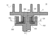
- FIG. 13 is a schematic view showing a vertical cross section of the slider balancer portion 302 of the scroll compressor 10 according to the second embodiment of the present invention.
- FIG. 14 is a cross-sectional view of the slider balancer portion 302 of FIG. 13 taken along the line CC. Note that, in FIG. 14, in order to explain the slider balancer portion 302, the boss portion 121 is omitted.
- the parts having the same configuration as that of the scroll compressor 1 of FIGS. 1 to 12 are denoted by the same reference numerals, and the description thereof will be omitted.
- the scroll compressor 10 according to the second embodiment of the present invention differs in the structure of the slider balancer 302 from the structure of the slider balancer 301 according to the first embodiment.
- the structure of the main shaft 15 of the scroll compressor 10 according to the second embodiment of the present invention is the same as the structure of the scroll compressor 1 according to the first embodiment.
- the main shaft 15 projects from the disk portion 155 in the direction opposite to the shaft portion 150 from the disk portion 155 protruding radially from the end portion of the shaft portion 150 at the upper end portion on the compression mechanism portion 2 side.
- an eccentric shaft portion 151 is provided at one end of the main shaft 15, as shown in FIG. 13, and the central axis C2 of the eccentric shaft 151 is eccentric to the central axis C1 of the main shaft 15.
- the peripheral wall portion 156 is provided at one end of the main shaft 15, has a central axis C1 identical to the main shaft 15, and forms an inner peripheral wall facing the outer peripheral surface of the boss portion 121, as shown in FIG.
- the variable radius crank mechanism 5 is disposed inside the peripheral wall portion 156.
- the peripheral wall portion 156 is formed in a cylindrical shape, and a notch portion 154 is formed in a part of the wall portion on the opposite side to the side where the eccentric shaft portion 151 is eccentric.
- the peripheral wall portion 156 of the main shaft 15 is, as shown in FIG. 5, from both ends of the counterbalance portion 152 constituting the wall portion of the semicircular portion on the side where the eccentric shaft portion 151 is eccentric; And a pair of stopper portions 153 that constitute extended wall portions.
- the stopper portion 153 is connected to the main shaft 15.
- the stopper portion 153 is a cylindrical peripheral wall portion which is formed at one end of the main shaft 15 and in which the variable radius crank mechanism 5 is disposed.
- the counterbalance portion 152 is provided at an end of the main shaft 15, and generates a centrifugal force in a direction opposite to a centrifugal force generated in a slider balancer 302 described later.
- the thickness of the counterbalance portion 152 is larger than the thickness of the pair of stopper portions 153, and the stopper portion 153 and the counterbalance portion 152 are integrally formed.
- line segment L1 is a virtual line segment passing through the central axis of main shaft 15 and the central axis of eccentric shaft portion 151.
- one side of the peripheral wall portion 156 is referred to as a U side with the virtual line segment L1 as a boundary, and the other side is referred to as a D side.
- the upper side in the drawing is the circumferential wall 156 on the U side
- the lower side in the drawing is the circumferential wall 156 on the D side.
- the peripheral wall portion 156 on the U side and the peripheral wall portion 156 on the D side have symmetrical shapes with a virtual line segment L1 passing through the center of the eccentric shaft portion 151 as a boundary.
- the moving member 30A is a member whose distance from the center of the main shaft 15 changes, is interposed between the boss portion 121 and the eccentric shaft portion 151, and determines the swing radius of the swing scroll 12.
- the moving member 30A has a cylindrical outer peripheral surface, and is provided rotatably and slidably on the inner peripheral side of the boss portion 121.
- the moving member 30A is, for example, a slider.
- the moving member 30A is formed with an elongated hole shaped groove portion 31 into which the eccentric shaft portion 151 is inserted slidably in one direction.
- the moving member 30A constitutes the variable radius crank mechanism 5 in combination with the eccentric shaft 151.
- the moving member 30A is not integrated with the slider balancer portion 302, and is a general bush-like shaped part.
- FIG. 14 shows the slider balancer 302 in the case where the number of rotations of the main shaft 15 is less than the threshold.
- the slider balancer portion 302 generates a centrifugal force that is reverse to the centrifugal force generated in the swinging part by the rotation of the main shaft 15.
- the slider balancer portion 302 generates a centrifugal force that exceeds the centrifugal force generated in the rocking component.
- the slider balancer portion 302 is disposed on the disk portion 155 between the moving member 30A and the peripheral wall portion 156.
- the slider balancer portion 302 includes a slider balancer portion 302c and a slider balancer portion 302d which are formed in symmetrical shapes on both sides of a virtual line segment L1 passing through the central axis of the main shaft 15 and the central axis of the eccentric shaft portion 151. It is configured.
- the slider balancer portion 302 has a structure divided into two, and includes a slider balancer portion 302 c disposed on the U side of the peripheral wall portion 156 and a slider balancer portion 302 d disposed on the D side of the peripheral wall portion 156.
- the slider balancer portion 302 includes two balance weights, a slider balancer portion 302c and a slider balancer portion 302d, which are disposed inside the peripheral wall portion 156 and whose mutual position is variable.
- the slider balancer portion 302c and the slider balancer portion 302d are formed in a symmetrical structure in plan view with the moving member 30A interposed therebetween.
- the slider balancer portion 302c and the slider balancer portion 302d correspond to "two balance weights" in the present invention.
- the slider balancer portion 302c and the slider balancer portion 302d are disposed so as not to contact with the moving member 30A and to sandwich the moving member 30A.
- the slider balancer portion 302 has a flat plate base portion 302a formed in a ring shape in plan view, and the inner peripheral side of the base portion 302a is disposed to face the outer peripheral side of the moving member 30A.
- the inner peripheral edge of the substrate portion 302a is formed larger than the outer diameter of the moving member 30A, and a gap is formed between the substrate portion 302a and the moving member 30A.
- a notch portion S ⁇ b> 3 is formed in a part of the eccentric shaft portion 151 in the eccentric direction.
- the slider balancer portion 302c has the base portion 302a1 formed in a flat plate and arc shape in which the inner peripheral edge is formed larger than the outer diameter of the moving member 30A and the moving member 30A is disposed on the inner peripheral side.
- the slider balancer portion 302d has a base portion 302a2 formed in a flat and arc shape in which the inner peripheral edge is formed larger than the outer diameter of the moving member 30A and the moving member 30A is disposed on the inner peripheral side.
- the notch portion S3 is a gap between the end portion 303c of the slider balancer portion 302c and the end portion 303d of the slider balancer portion 302d.
- An elastic member 26A is disposed between the end portion 303c of the slider balancer portion 302c and the end portion 303d of the slider balancer portion 302d as a mechanism for displacing the slider balancer portion 302. That is, in the substrate portion 302a, the elastic member 26A is disposed in the notch portion S3 formed in a part of the eccentric shaft portion 151 in the eccentric direction.
- the slider balancer unit 302 corresponds to the “balancer” in the present invention.
- the slider balancer portion 302 has a weight main body portion 302 b on the outer peripheral side of the substrate portion 302 a, which is opposite to the eccentric direction of the eccentric shaft portion 151.
- the weight main body portion 302b is integrally formed with the substrate portion 302a, and has a thickness in the axial direction of the main shaft 15 as compared with the substrate portion 302a. Further, the weight main body portion 302 b bulges into a notch portion 154 formed in the stopper portion 153.
- the weight main body portion 302b is constituted by the weight main body portion 302b1 of the slider balancer portion 302c and the weight main body portion 302b2 of the slider balancer portion 302d.
- the weight main body portion 302b1 of the slider balancer portion 302c and the weight main body portion 302b2 of the slider balancer portion 302d face each other.
- the weight main body portion 302b1 and the weight main body portion 302b2 are weights and cancel the centrifugal force generated in the rocking scroll 12 and other rocking parts.
- the elastic member 26A supports the load generated by the centrifugal force acting on the weight main body portion 302b1 and the weight main body portion 302b2 by the rotation of the main shaft 15.
- the elastic member 26A is a mechanism in which the slider balancer portion 302 is displaced by the change of the rotational speed of the main shaft 15.
- the elastic member 26A is disposed between the end portion 303c of the base portion 302a1 located opposite to the weight main portion 302b1 and the end portion 303d of the base portion 302a2 located opposite to the weight main portion 302b2. There is.
- the specific shape of the elastic member 26A is not shown in FIGS.
- the elastic member 26A is compressed, the displacement of the elastic member 26A is small, and a high load acts on the elastic member 26A.
- the elastic member 26 ⁇ / b> A like the elastic member 26 ⁇ / b> A used in the scroll compressor 1 according to the first embodiment, makes the position of the supporting reaction force at the time of deformation clear.
- a mechanical element such as a flat spring may be designed and used to have a predetermined spring constant, and there is no need to use a specific material having physical property values satisfying the predetermined condition.
- the scroll compressor 10 changes the ratio of supporting the centrifugal force of the slider balancer portion 302 by the stopper portion 153 and the moving member 30 of the variable radius crank mechanism 5 according to the change of the rotational speed of the main shaft 15.
- the configuration of the scroll compressor 1 will be described below.
- the slider balancer portion 302 is in contact with the inner peripheral wall of the peripheral wall portion 156 at the time of stop or low speed operation where the number of rotations of the main shaft 15 is less than the threshold value.
- one point of the outer edge portion of the slider balancer portion 302c is in contact with the stopper portion 153 on the U side of the peripheral wall portion 156 at the contact point U1
- one point of the outer edge portion of the slider balancer portion 302d is a stopper on the D side of the peripheral wall portion 156d.
- the portion 153 is in contact with the contact point D1.
- a gap is formed between the substrate portion 302a1 and the moving member 30A in plan view, and the gap between the slider balancer portion 302c and the stopper portion 153 is expanded from the contact point U1 to the notch portion 154.
- a gap S1 is formed.
- a gap is formed between the substrate portion 302a2 and the moving member 30A, and between the slider balancer portion 302d and the stopper portion 153, a notch is cut from the contact point D1.
- a gap S2 is formed which widens to 154.
- the weight main body portion 302b1 of the slider balancer portion 302c and the weight main body portion 302b2 of the slider balancer portion 302d are in contact with each other.
- the contact point U1 and the contact point D1 are located at the stopper portion 153 between the notch portion 154 of the peripheral wall portion 156 and the counterbalance portion 152.
- the slider balancer portion 302 is in contact with the inner peripheral wall of the peripheral wall portion 156 even when the number of rotations of the main shaft 15 is equal to or higher than the threshold. At this time, one point of the outer edge portion of the slider balancer portion 302c is in contact with the stopper portion 153 on the U side of the peripheral wall portion 156 at the contact point U1, and one point of the outer edge portion of the slider balancer portion 302d is a stopper on the D side of the peripheral wall portion 156d. The portion 153 contacts the contact D1. When the slider balancer portion 302c and the slider balancer portion 302d contact the stopper portion 153 at the contact point U1 and the contact point D1, the planar position and attitude of the slider balancer portion 302 are determined.
- the substrate portion 302a compresses the elastic member 26A and is in contact with the moving member 30A.
- a reaction force from the stopper portion 153 and the elastic member 26A acts on the slider balancer portion 302c and the slider balancer portion 302d with respect to the centrifugal force.
- a gap is formed between the weight main portions 302b of the two balance weights, that is, between the weight main portion 302b1 of the slider balancer portion 302c and the weight main portion 302b2 of the slider balancer portion 302d (described later) See Figure 15).
- the substrate portion 302a is formed with a gap S4 that expands from the inner peripheral side to the outer peripheral side.
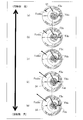
- FIG. 15 shows changes in centrifugal force and reaction force acting on the slider balancer portion 302c at each rotation speed from low speed operation (a) to high speed operation (e) of the scroll compressor 10 according to the second embodiment of the present invention. It is a top view for operation explanation which showed a.
- the contact point U1 with the stopper portion 153 on which the reaction force F3u acts is not on the line of the centrifugal force Fcsbu.
- the slider balancer portion 302c rotates so as to narrow the gap S1 with the point U1 as a fulcrum to cancel the moment, and the end portion 303c moves in the direction of the elastic member 26A.
- the slider balancer portion 302c slightly rotates about the point U1, and the substrate portion 302a contacts the moving member 30A.
- the reaction force Fdu from the elastic member 26A is generated in the portion 303c.
- the operation of the slider balancer portion 302d is also symmetrical to that of the slider balancer portion 302c, that is, the operation of being vertically symmetrical on the sheet of FIG. 15, the centrifugal force and reaction force acting on the slider balancer portion 302d are determined, and the slider balancer portion 302d is The attitude of is determined.
- the centrifugal force acting on the slider balancer 302 until the slider balancer 302c and the slider balancer 302d contact the moving member 30A is the main shaft 15 (stopper 153). Supported by the side). At this time, since the centrifugal force acting on each of the slider balancer portion 302c and the slider balancer portion 302d does not act on the variable radius crank mechanism 5 (moving member 30A) side, the canceling rate is 0%.
- the centrifugal force acting on the slider balancer portion 302 has a cancellation rate of 0% because it is all supported by the stopper portion 153.
- the centrifugal force acting on the slider balancer portion 302 is supported across the stopper portion 153 and the moving member 30A so that the cancellation rate becomes 0% or more.
- the cancel rate changes before the contact start with the moving member 30A and after the contact start with the moving member 30A.
- the cancellation rate of the centrifugal force acting on the slider balancer portion 302 is determined by the magnitude of the centrifugal force acting on the slider balancer portion 302, the center of gravity of the slider balancer portion 302, and the position of the contact point between the slider balancer portion 302 and the stopper portion 153. Ru. Furthermore, the cancellation rate of the centrifugal force acting on the slider balancer portion 302 is determined by the position where the reaction force of the elastic member 26A is generated, and the reaction force of the elastic member 26A at the start of contact between the slider balancer portion 302 and the moving member 30. .
- the scroll compressor 10 adjusts the design parameters to increase the number of rotations at which the slider balancer unit 302 and the moving member 30 start contact and the cancellation ratio after the start of the contact. Can be set.
- the scroll compressor 10 supports the centrifugal force of the slider balancer portion 302 only by either the stopper portion 153 or the moving member 30.
- the scroll compressor 10 changes the centrifugal force of the slider balancer portion 302 so that the stopper portion 153 and the moving member 30 support the centrifugal force.
- FIG. 16 is a graph showing a pattern of change with respect to the rotational speed [rps] of each bearing load and pressing force F [kgf] of the spiral side surface in the scroll compressor 10 according to Embodiment 2 of the present invention.
- FIG. 17 is a graph showing a change pattern of the centrifugal force of the swinging component in the scroll compressor 10 according to Embodiment 2 of the present invention with respect to the rotational speed [rps] of the support ratio of the swing bearing and the spiral side surface.
- FIGS. 16 and 17 An example of the cancellation characteristic of the scroll compressor 10 according to the second embodiment of the present invention is shown using FIGS. 16 and 17.
- FIG. 16 shows the changes in the pressing force Fs on the spiral side surface, the swing bearing load Fbo, the main bearing load Fbm, and the auxiliary bearing load Fbs with the horizontal axis as the number of rotations of the main shaft 15.
- FIG. 17 makes a horizontal axis the rotation speed of the main axis
- the cancel imbalance amount of each of the slider balancer portion 302c and the slider balancer portion 302d is 60% (120% in total) in the positional relationship in the plan view of FIG. .
- the slider balancer portion 302c and the slider balancer portion 302d contact the moving member 30A when the number of rotations of the main shaft 15 is 90 rps or more.
- the support ratio of the centrifugal force is 100% of the rocking bearing, the spiral side surface up to 90 rps when the semi-supported slider balancer portion 301b starts contacting the stopper portion 153. It will be at 0%.
- the scroll compressor 10 according to the second embodiment of the present invention is centrifugal until 90 rps at which the slider balancer portion 302 starts contacting the moving member 30A.
- the force support ratio changes at 0% of the swing bearing and 100% of the spiral side surface.
- the slider balancer portion 301 is supported by the spiral side surface by both the rocking bearing and the spiral side surface in the high speed region where the rotational speed is equal to or more than the threshold. Transfer to support.
- the scroll compressor 10 has the stopper portion 153 connected to the main shaft 15 and the mechanism in which the slider balancer portion 302 is displaced by the change of the rotational speed of the main shaft 15.
- the ratio of supporting the centrifugal force of the slider balancer portion 302 by the stopper portion 153 and the moving member 30 of the variable radius crank mechanism changes according to the change of the rotational speed of the main shaft 15. Therefore, the scroll compressor 10 can automatically change the instruction ratio of the spiral side surface of the centrifugal force of the rocking component and the rocking bearing depending on the rotational speed.
- the centrifugal force acting on the rocking parts is 100% supported by the rocking bearing or spiral side at low speed rotation below the threshold, and each of the rocking bearings in the high speed rotation area above the threshold close to the upper limit rotational speed It can be supported at a ratio that takes into consideration the load capacity and the sliding characteristics of the spiral side surface.
- the scroll compressor 10 can have characteristics such as centrifugal force dispersion support at high speed operation, side sealability at low speed operation, and quietness at medium to high speed operation. Therefore, the scroll compressor 10 can ensure the reliability up to the high rotation speed region, and can be a compressor with a wide capacity range.
- the scroll compressor 10 when the rotation of the main shaft 15 is low, only the stopper portion 153 or the moving member 30 supports the centrifugal force of the slider balancer 302, and the rotational speed of the main shaft 15 increases.
- the centrifugal force of the portion 302 is changed so that the stopper portion 153 and the moving member 30 support. Therefore, the scroll compressor 10 can automatically change the instruction ratio of the spiral side surface of the centrifugal force of the rocking component and the rocking bearing depending on the rotational speed.
- the centrifugal force acting on the rocking parts is 100% supported by the rocking bearing or spiral side at low speed rotation below the threshold, and each of the rocking bearings in the high speed rotation area above the threshold close to the upper limit rotational speed It can be supported at a ratio that takes into consideration the load capacity and the sliding characteristics of the spiral side surface.
- the scroll compressor 10 can have characteristics such as centrifugal force dispersion support at high speed operation, side sealability at low speed operation, and quietness at medium to high speed operation. Therefore, the scroll compressor 10 can ensure the reliability up to the high rotation speed region, and can be a compressor with a wide capacity range.
- the stopper portion 153 is a cylindrical peripheral wall portion which is formed at one end of the main shaft and in which the variable radius crank mechanism is disposed. Therefore, the stopper portion 153 can restrict the movement of the slider balancer portion 302 in the radial direction.
- the scroll compressor 10 includes two balance weights in which the slider balancer portion 302 is disposed inside the peripheral wall portion 156 and the mutual position is variable.
- the movement of the two balance weights inside the peripheral wall portion 156 automatically changes the indicated ratio of the spiral side surface of the centrifugal force of the rocking component and the rocking bearing depending on the rotational speed. It can be done.
- the scroll compressor 10 includes two slider balancers 302 c and a slider balancer 302 d between the moving member 30 A and the peripheral wall 156.
- the two slider balancer portions 302c and the slider balancer portion 302d have a substrate portion 302a1 formed in a flat plate and arc shape in which the inner peripheral edge is formed larger than the outer diameter of the moving member 30A and the moving member 30A is disposed on the inner peripheral side. And a substrate portion 302a1.
- the two slider balancer portions 302c and 302b are provided with a weight body portion 302b1 and a weight body portion 302b1 provided on the outer peripheral edge of the substrate portion 302a1 and the substrate portion 302a1 opposite to the eccentric direction of the eccentric shaft 151.
- the two slider balancer portions 302c and the slider balancer portions 302d are formed in a symmetrical structure in plan view with the moving member 30A interposed therebetween.
- the centrifugal force acting on the rocking parts is 100% supported by the rocking bearing or spiral side at low speed rotation below the threshold, and each of the rocking bearings in the high speed rotation area above the threshold close to the upper limit rotational speed It can be supported at a ratio that takes into consideration the load capacity and the sliding characteristics of the spiral side surface.
- the scroll compressor 10 can have characteristics such as centrifugal force dispersion support at high speed operation, side sealability at low speed operation, and quietness at medium to high speed operation. Further, the scroll compressor 10 can ensure reliability up to the high rotation speed range, and can be a compressor having a wide capacity range.
- one point of the outer edge of the slider balancer portion 302c and the outer edge portion of the slider balancer portion 302d is in contact with the stopper portion 153, respectively.
- a gap is formed between the substrate portion 302a and the moving member 30A.
- the substrate portion 302a compresses the elastic member 26A and is in contact with the moving member 30A when the number of rotations of the main shaft 15 is equal to or greater than the threshold.
- the scroll compressor 10 Since the scroll compressor 10 is provided with these configurations, all reaction forces of centrifugal force are supported on the main shaft 15 side having the stopper portion 153 at low speed operation, so that the centrifugal force acting on the swinging parts has a spiral side surface. Sealability is secured by contributing to pressing.
- the base portion 302a At the time of high speed operation with a rotational speed equal to or higher than the threshold, the base portion 302a contacts the moving member 30A, and the ratio of supporting the reaction force of the centrifugal force on the crank mechanism side increases. It can avoid that the pressing force to a side becomes excessive.
- the scroll compressor 10 can automatically change the support ratio of the centrifugal force of the rocking component depending on the number of rotations of the main shaft 15 between the spiral side surface and the rocking bearing. Therefore, the scroll compressor 10 can have characteristics such as centrifugal force dispersion support at high speed operation, side sealability at low speed operation, and quietness at medium to high speed operation.
- Reference Signs List 1 scroll compressor, 1 t scroll compressor, 2 compression mechanism portion, 3 electric motor, 5 variable radius crank mechanism, 5 t variable radius crank mechanism, 10 scroll compressor, 11 fixed scroll, 11 t fixed scroll, 12 rocking scroll, 12 t rock Dynamic scroll, 13 Oldham rings, 14 frames, 15 spindles, 15t spindles, 16 first balancers, 17 second balancers, 18 rotors, 19 stators, 20 auxiliary bearings, 21 closed containers, 22 lubricating oil, 23 suction pipes, 24 discharges Tube, 25 discharge valve, 26 elastic member, 26A elastic member, 28 sub frame, 30 moving member, 30A moving member, 30t slider, 31 groove portion, 35 substrate portion, 36 notch portion, 37 side surface portion, 111 discharge port, 113 Base plate, 14 spiral tooth, 114t spiral tooth, 121 boss portion, 121t boss portion, 122 base plate portion, 126 spiral tooth, 126t spiral tooth, 141 overhang portion, 143 main bearing, 150 base shaft portion, 151 eccentric shaft portion, 151t eccentric
Landscapes
- Engineering & Computer Science (AREA)
- Mechanical Engineering (AREA)
- General Engineering & Computer Science (AREA)
- Rotary Pumps (AREA)
Abstract
Ce compresseur à spirale comprend : une section mécanisme de compression comportant une volute fixe et une volute orbitale qui tourne par rapport à la volute fixe ; un arbre principal rotatif ; un mécanisme à manivelle radiale variable qui, par l'intermédiaire d'un élément de déplacement, transmet la force de rotation de l'arbre principal en tant que force qui amène la volute orbitale à tourner, la distance de l'élément de déplacement par rapport au centre de l'arbre principal étant variable ; et un dispositif d'équilibrage qui génère une force centrifuge qui agit dans la direction opposée à la direction de la force centrifuge générée dans un composant orbital par la rotation de l'arbre principal. Le compresseur à spirale comporte en outre une section d'arrêt qui se raccorde à l'arbre principal, et un mécanisme dans lequel le dispositif d'équilibrage est déplacé par une variation de la vitesse de rotation de l'arbre principal. La variation de la vitesse de rotation de l'arbre principal change le rapport entre lorsque la force centrifuge du dispositif d'équilibrage est supportée par la section d'arrêt et lorsque la force centrifuge est soutenue par l'élément de déplacement du mécanisme à manivelle radiale variable.
Priority Applications (2)
| Application Number | Priority Date | Filing Date | Title |
|---|---|---|---|
| JP2019547540A JP6632784B2 (ja) | 2017-10-13 | 2017-10-13 | スクロール圧縮機 |
| PCT/JP2017/037229 WO2019073605A1 (fr) | 2017-10-13 | 2017-10-13 | Compresseur à spirale |
Applications Claiming Priority (1)
| Application Number | Priority Date | Filing Date | Title |
|---|---|---|---|
| PCT/JP2017/037229 WO2019073605A1 (fr) | 2017-10-13 | 2017-10-13 | Compresseur à spirale |
Publications (1)
| Publication Number | Publication Date |
|---|---|
| WO2019073605A1 true WO2019073605A1 (fr) | 2019-04-18 |
Family
ID=66100549
Family Applications (1)
| Application Number | Title | Priority Date | Filing Date |
|---|---|---|---|
| PCT/JP2017/037229 Ceased WO2019073605A1 (fr) | 2017-10-13 | 2017-10-13 | Compresseur à spirale |
Country Status (2)
| Country | Link |
|---|---|
| JP (1) | JP6632784B2 (fr) |
| WO (1) | WO2019073605A1 (fr) |
Cited By (2)
| Publication number | Priority date | Publication date | Assignee | Title |
|---|---|---|---|---|
| CN110005607A (zh) * | 2019-04-30 | 2019-07-12 | 南安紫鲸铃工业设计有限公司 | 一种涡旋压缩机背压装置 |
| JP2023014161A (ja) * | 2018-03-30 | 2023-01-26 | 株式会社豊田自動織機 | スクロール型圧縮機 |
Citations (3)
| Publication number | Priority date | Publication date | Assignee | Title |
|---|---|---|---|---|
| JPS63159689A (ja) * | 1986-12-23 | 1988-07-02 | Sanyo Electric Co Ltd | スクロ−ル圧縮機 |
| JPH03275902A (ja) * | 1990-03-23 | 1991-12-06 | Mitsubishi Heavy Ind Ltd | スクロール型流体機械 |
| JPH09195957A (ja) * | 1996-01-17 | 1997-07-29 | Nippon Soken Inc | スクロール型圧縮機 |
-
2017
- 2017-10-13 JP JP2019547540A patent/JP6632784B2/ja not_active Expired - Fee Related
- 2017-10-13 WO PCT/JP2017/037229 patent/WO2019073605A1/fr not_active Ceased
Patent Citations (3)
| Publication number | Priority date | Publication date | Assignee | Title |
|---|---|---|---|---|
| JPS63159689A (ja) * | 1986-12-23 | 1988-07-02 | Sanyo Electric Co Ltd | スクロ−ル圧縮機 |
| JPH03275902A (ja) * | 1990-03-23 | 1991-12-06 | Mitsubishi Heavy Ind Ltd | スクロール型流体機械 |
| JPH09195957A (ja) * | 1996-01-17 | 1997-07-29 | Nippon Soken Inc | スクロール型圧縮機 |
Cited By (4)
| Publication number | Priority date | Publication date | Assignee | Title |
|---|---|---|---|---|
| JP2023014161A (ja) * | 2018-03-30 | 2023-01-26 | 株式会社豊田自動織機 | スクロール型圧縮機 |
| JP7380811B2 (ja) | 2018-03-30 | 2023-11-15 | 株式会社豊田自動織機 | スクロール型圧縮機 |
| CN110005607A (zh) * | 2019-04-30 | 2019-07-12 | 南安紫鲸铃工业设计有限公司 | 一种涡旋压缩机背压装置 |
| CN110005607B (zh) * | 2019-04-30 | 2020-12-04 | 浙江颐顿机电有限公司 | 一种涡旋压缩机背压装置 |
Also Published As
| Publication number | Publication date |
|---|---|
| JPWO2019073605A1 (ja) | 2019-11-21 |
| JP6632784B2 (ja) | 2020-01-22 |
Similar Documents
| Publication | Publication Date | Title |
|---|---|---|
| CN106499628B (zh) | 涡旋压缩机 | |
| JP6903826B2 (ja) | スクロール圧縮機における動的半径方向コンプライアンス | |
| JPH03222801A (ja) | スクロール流体機械 | |
| JPH07253084A (ja) | スクロール型機械 | |
| JPH0545800B2 (fr) | ||
| CN110319001A (zh) | 涡旋型压缩机 | |
| CN108603500B (zh) | 涡旋压缩机 | |
| JPH06346863A (ja) | スクロール圧縮機の旋回スクロール駆動装置 | |
| CN100371603C (zh) | 径向顺从性涡旋式压缩机中的偏心衬套装置 | |
| JPH0263117B2 (fr) | ||
| JP6632784B2 (ja) | スクロール圧縮機 | |
| JPH04321785A (ja) | スクロール圧縮機の可変クランク機構 | |
| JPH0152591B2 (fr) | ||
| JPH07208351A (ja) | スクロール圧縮機 | |
| JP2011127435A (ja) | スクロール圧縮機 | |
| JPH02149783A (ja) | スクロール形流体機械 | |
| JPH01262393A (ja) | スクロール圧縮機 | |
| JP2020112143A (ja) | スクロール型流体機械 | |
| CN112384699B (zh) | 涡旋式压缩机 | |
| JPH09170572A (ja) | スクロール型流体機械 | |
| JP4618645B2 (ja) | スクロール圧縮機 | |
| JP7408011B2 (ja) | 二段スクロール圧縮機 | |
| JPH0330684B2 (fr) | ||
| KR20250100849A (ko) | 전동압축기의 회전축 | |
| JPH0343476B2 (fr) |
Legal Events
| Date | Code | Title | Description |
|---|---|---|---|
| 121 | Ep: the epo has been informed by wipo that ep was designated in this application |
Ref document number: 17928778 Country of ref document: EP Kind code of ref document: A1 |
|
| ENP | Entry into the national phase |
Ref document number: 2019547540 Country of ref document: JP Kind code of ref document: A |
|
| NENP | Non-entry into the national phase |
Ref country code: DE |
|
| 122 | Ep: pct application non-entry in european phase |
Ref document number: 17928778 Country of ref document: EP Kind code of ref document: A1 |