WO2019077793A1 - Matériau de revêtement isolant pour bobines de stator et machine rotative l'utilisant - Google Patents
Matériau de revêtement isolant pour bobines de stator et machine rotative l'utilisant Download PDFInfo
- Publication number
- WO2019077793A1 WO2019077793A1 PCT/JP2018/019885 JP2018019885W WO2019077793A1 WO 2019077793 A1 WO2019077793 A1 WO 2019077793A1 JP 2018019885 W JP2018019885 W JP 2018019885W WO 2019077793 A1 WO2019077793 A1 WO 2019077793A1
- Authority
- WO
- WIPO (PCT)
- Prior art keywords
- particle
- core
- particles
- mica
- stator
- Prior art date
- Legal status (The legal status is an assumption and is not a legal conclusion. Google has not performed a legal analysis and makes no representation as to the accuracy of the status listed.)
- Ceased
Links
Images


Classifications
-
- H—ELECTRICITY
- H01—ELECTRIC ELEMENTS
- H01B—CABLES; CONDUCTORS; INSULATORS; SELECTION OF MATERIALS FOR THEIR CONDUCTIVE, INSULATING OR DIELECTRIC PROPERTIES
- H01B17/00—Insulators or insulating bodies characterised by their form
- H01B17/56—Insulating bodies
- H01B17/60—Composite insulating bodies
-
- H—ELECTRICITY
- H01—ELECTRIC ELEMENTS
- H01B—CABLES; CONDUCTORS; INSULATORS; SELECTION OF MATERIALS FOR THEIR CONDUCTIVE, INSULATING OR DIELECTRIC PROPERTIES
- H01B3/00—Insulators or insulating bodies characterised by the insulating materials; Selection of materials for their insulating or dielectric properties
-
- H—ELECTRICITY
- H01—ELECTRIC ELEMENTS
- H01B—CABLES; CONDUCTORS; INSULATORS; SELECTION OF MATERIALS FOR THEIR CONDUCTIVE, INSULATING OR DIELECTRIC PROPERTIES
- H01B3/00—Insulators or insulating bodies characterised by the insulating materials; Selection of materials for their insulating or dielectric properties
- H01B3/02—Insulators or insulating bodies characterised by the insulating materials; Selection of materials for their insulating or dielectric properties mainly consisting of inorganic substances
- H01B3/04—Insulators or insulating bodies characterised by the insulating materials; Selection of materials for their insulating or dielectric properties mainly consisting of inorganic substances mica
-
- H—ELECTRICITY
- H01—ELECTRIC ELEMENTS
- H01F—MAGNETS; INDUCTANCES; TRANSFORMERS; SELECTION OF MATERIALS FOR THEIR MAGNETIC PROPERTIES
- H01F5/00—Coils
- H01F5/06—Insulation of windings
-
- H—ELECTRICITY
- H02—GENERATION; CONVERSION OR DISTRIBUTION OF ELECTRIC POWER
- H02K—DYNAMO-ELECTRIC MACHINES
- H02K15/00—Processes or apparatus specially adapted for manufacturing, assembling, maintaining or repairing of dynamo-electric machines
- H02K15/12—Impregnating, moulding insulation, heating or drying of windings, stators, rotors or machines
-
- H—ELECTRICITY
- H02—GENERATION; CONVERSION OR DISTRIBUTION OF ELECTRIC POWER
- H02K—DYNAMO-ELECTRIC MACHINES
- H02K3/00—Details of windings
- H02K3/30—Windings characterised by the insulating material
-
- H—ELECTRICITY
- H02—GENERATION; CONVERSION OR DISTRIBUTION OF ELECTRIC POWER
- H02K—DYNAMO-ELECTRIC MACHINES
- H02K3/00—Details of windings
- H02K3/32—Windings characterised by the shape, form or construction of the insulation
- H02K3/34—Windings characterised by the shape, form or construction of the insulation between conductors or between conductor and core, e.g. slot insulation
Definitions
- the present invention relates to an insulating covering material used for a stator coil of a rotating machine, and a rotating machine using the same.
- a large-sized rotating machine used for a turbine generator or the like has a stator coil housed in a plurality of slots formed on the inner peripheral side of a stator core.
- the stator coil is composed of a coil conductor and an insulating covering material wound around it.
- an insulating tape obtained by bonding a fiber reinforcing material such as glass cloth to a mica sheet is wound around the coil conductor a plurality of times, and a low viscosity liquid thermosetting resin composition (insulating varnish) is obtained.
- a method of heat pressing after impregnation under reduced pressure (vacuum pressure impregnation method) or a method of placing a semi-cured resin on an insulating tape, winding this tape around a coil conductor and then heating pressing (resin rich method) are generally used.
- stator coils are housed in upper and lower two stages in the slot, and a spacer is inserted between these stator coils and the stator coil is fixed to the open end of the slot By inserting the wedge, the electromagnetic vibration generated from the stator coil during operation of the rotating machine is suppressed.
- the stator coil In such a rotating machine, the stator coil generates heat due to the current flowing through the coil conductor during operation. If the temperature of the stator coil rises due to this heat generation, there is a fear that the insulation of the stator coil may be deteriorated due to thermal expansion of the coil conductor made of metal such as copper or thermal degradation of the resin component contained in the insulation coating material. There is.
- the thermal conductivity of the insulation coating material is very small compared to the thermal conductivity of other materials such as the coil conductor and the stator core, so it is necessary to increase the thermal conductivity of the insulation coating material
- forced rotation methods such as water direct cooling method and hydrogen indirect cooling method are adopted in rotating machines where large current flows, such as turbine generators, and it is strongly desired to increase the thermal conductivity of the insulation coating of stator coils ing.
- the insulation coating material of the stator coil is also desired to improve the withstand voltage performance.
- a conventional stator coil insulation coating material includes a mica layer, a reinforcing layer laminated on the mica layer and containing filler particles and a fiber reinforcing material, and a cellulose derivative layer laminated on the reinforcing layer.
- An insulating covering material is disclosed (see, for example, Patent Document 1).
- the insulation coating material comprised with the filler layer containing a mica layer and a filler particle as an insulation coating material of another stator coil what used the scale-like hexagonal boron nitride filler particle as a filler particle is disclosed. (See, for example, Patent Document 2).
- the generation of the electrical tree can not be suppressed, and it is difficult to improve the withstand voltage performance.
- the present invention has been made to solve the problems as described above, and it is an object of the present invention to simultaneously achieve high thermal conductivity and high withstand voltage of the insulation coating material of the stator coil.
- the insulation coating material of the stator coil according to the present invention has the mica layer containing mica and the reinforcing layer laminated on the mica layer and containing the filler particles and the reinforcing material, and the filler particles have an average particle diameter of
- the composite particle is composed of core particles of 1 ⁇ m or more and a plurality of fine particles having an average particle diameter of 300 nm or less fixed on the surface of the core particles.
- the present invention uses composite particles composed of core particles and a plurality of fine particles fixed on the surface of the core particles as the filler particles of the reinforcing layer. Coexistence with high withstand voltage can be realized.
- FIG. 1 is a schematic view showing an enlarged part of a stator of a rotary machine according to Embodiment 1 for carrying out the present invention.
- stator coils 3 are accommodated in two stages in slots 2 of a stator core 1.
- a spacer is inserted between the two stages of stator coils 3 (not shown), and a wedge 4 for fixing the stator coil 3 is inserted into the open end of the slot 2.
- the wedge 4 has an effect of suppressing electromagnetic vibration generated from the stator coil 3 at the time of operation of the rotating machine.
- the stator coil 3 is composed of a coil conductor 5 and an insulating covering material 6 wound around the outer periphery of the coil conductor 5.
- the coil conductor 5 can use, for example, a strand of copper, aluminum, silver or the like.
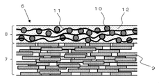
- FIG. 2 is a schematic cross-sectional view of the insulating covering material 6 in the present embodiment.
- the insulating covering material 6 of the present embodiment is configured of a mica layer 7 and a reinforcing layer 8 laminated on the mica layer.
- the mica layer 7 and the reinforcing layer 8 are filled with an insulating resin material 12.
- the mica layer 7 is composed of mica particles 9.
- mica particles 9 it is possible to use scale-like mica, for example, hard mica or soft mica which is a layered silicate rim mineral.
- examples of the form of the mica particles 9 include block mica, peeled mica, and assembled mica. Among these, it is preferable to use an integrated mica having a uniform thickness and an economic advantage.
- the mica layer 7 is configured by laminating flat surfaces of scaly mica particles 9 in the thickness direction of the mica layer. These mica particles are present in such a manner that the particles to be stacked overlap each other, or the particles are shifted in the surface direction.
- the density of the mica layer 7 is preferably 100 to 200 g / m 2 of the mica layer. Within this range, the balance between the withstand voltage performance and the film thickness of the mica layer is good, and the electrical insulating property and the workability for forming the insulating coating material around the coil conductor are compatible.
- These mica particles are obtained by micronizing the ore of mica by water grinding, shear grinding or the like.
- the average particle size of the mica particles is desirably 50 to 800 ⁇ m.
- the average particle size of the mica particles can be measured by a laser diffraction type particle size distribution analyzer.
- the thickness of the scaly mica particles is preferably 30 ⁇ m or less, and more preferably 15 ⁇ m or less.
- the reinforcing layer 8 is laminated on the mica layer 7 and is provided to maintain the strength of the insulating covering material 6 and to improve the workability in the process of winding the insulating covering material 6 around the outer periphery of the coil conductor 5.
- the reinforcing layer 8 is composed of the filler particles 10 and the reinforcing material 11.
- a fibrous material or a film-like material can be used as the reinforcing material 11.
- a fibrous material glass fiber, alumina fiber, polyamide fiber etc. can be used, for example.
- a film-form material a polyimide film, a polyamide film, a polyester film etc. can be used, for example.
- glass fiber is excellent in terms of properties and price. Although there are glass fibers subjected to a coupling treatment on the surface for the purpose of improving the adhesion to the resin, it is preferable that the glass fibers be untreated because this treatment tends to lower the strength of the glass fibers themselves.
- the weight of those deposits is preferably 3% or less of the glass fiber weight.
- the above adhesion weight ratio can be estimated as a weight loss when the glass fiber is heated at 900 ° C. for 30 hours. When the adhesion weight ratio exceeds 3%, peeling occurs between the resin and the glass fiber in aged use, and the insulation performance is reduced.
- the filler particles 10 are held in the gaps of the reinforcing material 11.
- the reinforcing material 11 is a fibrous material, it is held between the fibers, and when the reinforcing material 11 is a film-like material, it is held between the layers of the film.
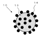
- FIG. 3 is a schematic view of the filler particle 10 in the present embodiment.
- the filler particle 10 is a composite particle composed of a core particle 13 having a particle size of 1 ⁇ m or more and a plurality of fine particles 14 having an average particle size of 300 nm or less fixed to the surface of the core particle 13.
- the core particles 13 are insulating inorganic particles such as silica, boron nitride, alumina, magnesia, aluminum nitride, magnesium hydroxide, magnesium oxide, calcium carbonate and magnesium carbonate.
- the thermal conductivity of these insulating inorganic particles is higher than the thermal conductivity of the resin material filled in the reinforcing layer, so the thermal conductivity of the reinforcing layer can be improved.
- the core particle 13 is preferably a spherical dense particle. If it is spherical, suppression of mechanical destruction, such as a crack at the time of the stress load to insulation coating material, and suppression of the dielectric breakdown by the electric field concentration of particle periphery can be anticipated.
- the dense particles that is, the inside of the particles be free of voids and be filled with the above-described insulating material. The packing of the insulating material improves the thermal conductivity inside the particle, and as a result, the thermal conductivity of the reinforcing layer improves.
- the particle size said here is a value obtained by observing the cross section of insulation coating material with an electron microscope, and observing the particle size of the particle
- the fine particles 14 are also insulating inorganic particles such as silica, boron nitride, alumina, magnesia, aluminum nitride, magnesium hydroxide, magnesium oxide, calcium carbonate and magnesium carbonate.
- the fine particles 14 are mechanically or chemically fixed to the surface of the core particle 13.
- the filler particle 10 By forming the filler particle 10 as a composite particle including the core particle 13 having a particle diameter of 1 ⁇ m to 100 ⁇ m and the plurality of fine particles 14 having an average particle diameter of 300 nm or less fixed on the surface of the core particle 13, The ability to increase the withstand voltage of the insulation coating material will be described next.
- an electrical tree may occur inside the insulating resin filled in the reinforcing layer.
- the electrical tree propagates in the resin in a lightning-like manner, but when the front end of the electrical tree reaches the filler particle, it propagates along the interface between the filler particle and the resin, that is, the surface of the filler particle. The reason is that the difference between the dielectric constant of the filler particles and the dielectric constant of the resin causes the surface of the filler particles to locally increase the electric field strength.
- the tip of the electrical tree reaching the surface of the filler particle travels along the surface of the filler particle according to the electric field strength distribution substantially uniformly distributed on the surface of the filler particle Be
- the filler particles were composite particles composed of core particles and fine particles
- the electric field strength distribution on the surface of the core particles reached the surface of the core particles because the cloth was deformed largely due to the presence of the fine particles.
- the tip of the electrical tree will diverge and evolve. It is believed that part of the branched electrical tree spreads to the resin away from the filler particles, and the development of the electrical tree is suppressed because the electric field strength is lower than that of the surface of the core particle.
- the interparticle distance of the plurality of fine particles on the surface of the core particle is 500 nm or less.
- the probability that an electrical tree traveling on the surface of the core particle encounters the microparticles and is branched increases.
- the number of the fine particles fixed to the outer peripheral part of the hemisphere of the core particle is other than the hemisphere. It is preferably 25% or more and 400% or less of the number of particles fixed to the outer peripheral portion, and more preferably 50% or more and 200% or less. Within these ranges, there is a high probability that the tip of the electrical tree reaching the surface of the core particle is branched even if the electrical tree develops from all directions of the filler particles.
- the electrical tree will become those when the tip of the electrical tree reaches the surface of the core particle or particulate.
- the probability of branching is low only by progressing according to the electric field intensity distribution distributed almost uniformly on the surface of the particles of. As a result, the effect of suppressing the development of the electrical tree is small.
- the particle size of the core particle 13 constituting the composite particle needs to be 1 ⁇ m or more and 100 ⁇ m or less. If the particle size of the core particle is smaller than 1 ⁇ m, the thermal conductivity at the interface between the resin and the core particle is increased, the effect of improving the thermal conductivity by the core particle is reduced, and the desired high thermal conductivity effect can not be obtained. is there.
- the particle size of the core particles exceeds 100 ⁇ m and the thickness of the coil insulating material is constant, the thickness of the reinforcing layer 8 increases due to the increase of the particle size, so the thickness of the mica layer 7 becomes relatively thin and the insulation coating There is a problem that the strength of the material decreases. Furthermore, when the thickness of the insulating covering material is increased when the particle size of the particles exceeds 100 ⁇ m, there is a problem that the thermal resistance of the insulating covering material increases and the heat dissipation decreases.
- the particle diameter of the fine particles 14 constituting the composite particles needs to be 300 nm or less. If the particle size of the fine particles exceeds 300 nm, the probability of the electric tree developing on the surface of the fine particles without branching is high, so that there is a problem that the effect of the fine particles on suppressing the progress of the electric tree decreases.
- the partial discharge repeatedly occurs due to high electric field stress inside the insulation coating material, and the voids resulting from the thermal decomposition of the resin are generated and enlarged.
- the withstand voltage performance of the resin it is preferable to improve the adhesion between the surface of the core particles and the fine particles and the resin.
- the coupling agent for surface modification of these particles can be appropriately selected according to the type of the resin, but when the resin is an epoxy resin, 3-glycidoxypropylmethyldimethoxysilane, 3-glidoxy Cidoxypropyltrimethoxysilane, 3-glycidoxypropylmethyldiethoxysilane, 3-glycidoxypropyltriethoxysilane, 2- (3,4-epoxycyclohexyl) ethyltrimethoxysilane, p-styryltrimethoxysilane, It is desirable to use any one or more of 3-methacryloxypropylmethyldimethoxysilane, 3-methacryloxypropyltrimethoxysilane, 3-methacryloxypropylmethyldiethoxysilane, and 3-methacryloxypropyltriethoxysilane.
- the insulating resin material filled in the mica layer 7 and the reinforcing layer 8 is preferably an epoxy resin, a phenol resin, a silicon resin or an imide resin from the viewpoint of heat resistance, adhesion, electrical insulation and mechanical strength, particularly the resin Among them, epoxy resin is preferable.
- epoxy resin examples include epoxy group in the skeleton, and bisphenol A epoxy resin, bisphenol F epoxy resin, bisphenol S epoxy resin, biphenol epoxy resin, phenol novolac epoxy resin, cresol novolac epoxy Resin, bisphenol A novolac epoxy resin, bisphenol F novolac epoxy resin, alicyclic epoxy resin, aliphatic chain epoxy resin, glycidyl ester epoxy resin, glycidyl amine epoxy resin, hydantoin epoxy resin, isocyanurate Type epoxy resin, salicylaldehyde novolac type epoxy resin, diglycidyl ether compounds of other bifunctional phenols, diglycidyl ether compounds of difunctional alcohols and the like Et halide, such as hydrogen additives and the like, which may be used in combination several types.
- the reaction product of epichlorohydrin and a bisphenol A compound is preferable from the balance of cost, viscosity, and heat resistance.
- the products include Epicoat 828, Epicoat 825 (trade name: made by Yuka Shell Epoxy Co., Ltd.), Epototo YD128 (trade name: made by Toto Kasei Co., Ltd.), Epiclon 850 (trade name: Dai Nippon Ink Chemical Industrial Co., Ltd. product, Sumi epoxy ELA-128 (brand name: Sumitomo Chemical Co., Ltd. product) etc. are mentioned.
- an epoxy resin containing three or more epoxy groups can be used alone or in combination with the above epoxy resin.
- these resins can improve heat resistance according to the addition amount, generally the viscosity is high and the workability of the step of forming the coil insulation coating material is lowered, so a balance between the addition amount and the heat resistance is required. .
- phenol novolac epoxy or cresol novolac epoxy is particularly preferable.
- epoxy resins although it will not be specifically limited if it can harden an epoxy resin, for example, the following acid anhydride, an amine compound, and an imidazole compound are mentioned.
- hexahydrophthalic anhydride hexahydrophthalic anhydride, tetrahydrophthalic anhydride, methylhexahydrophthalic anhydride, methyltetrahydrophthalic anhydride, methyl nadic anhydride and the like can be mentioned. These can be used alone or in combination of two or more.
- the compounding amount of the acid anhydride is not particularly limited, and may be appropriately adjusted according to the type of acid anhydride to be used.
- the compounding amount of the acid anhydride is preferably 10 parts by mass to 150 parts by mass, more preferably 30 parts by mass to 120 parts by mass, and still more preferably 50 parts by mass to 100 parts by mass with respect to 100 parts by mass of bisphenol epoxy resin is there. If it is such a compounding quantity, hardening of a thermosetting resin composition can be performed appropriately.
- the equivalent ratio of the acid anhydride group of the acid anhydride to the epoxy group of the bisphenol type epoxy resin is not particularly limited, but preferably 0.7 to 1.3, more preferably 0.8 to 1.2, and further preferably Preferably, it is 0.9 to 1.1. If this equivalent ratio is less than 0.7, the workability of the molding process of the insulation coating material tends to decrease. On the other hand, when this equivalent ratio exceeds 1.3, the heat resistance of the cured product and the like tend to decrease.
- examples of the amine-based curing agent include, for example, ethylene diamine, 1,3-diaminopropane, 1,4-diaminobutane, hexamethylene diamine, dipropene diamine, polyether diamine, 2, 5-dimethyl hexa methylene diamine, trimethyl hexa Methylenediamine, diethylenetriamine, iminobispropylamine, bis (hexamethyl) triamine, triethylenetetramine, tetraethylenepentamine, pentaethylenehexamine, aminoethylethanolamine, tri (methylamino) hexane, dimethylaminopropylamine, diethylaminopropylamine Methyliminobispropylamine, mensene diamine, isophorone diamine, bis (4-amino-3-methyldicyclohexyl) methane, diaminodicycline Hexylmethane, bis (aminomethyl) cyclo
- examples of the imidazole-based curing agent include 2-methylimidazole, 2-undecylimidazole, 1,2-dimethylimidazole, 2-ethyl-4-methylimidazole, 2-heptadecylimidazole, 2-phenylimidazole, 2 -Phenyl-4-methylimidazole, 1-benzyl-2-methylimidazole, 1-benzyl-2-phenylimidazole and the like, but not limited thereto.
- a reactive diluent can be added to these epoxy resin and curing agent as a third component, as appropriate.
- a styrene monomer, or a monomer having a functional group of hydrocarbon added to its phenyl group, or a methacrylic monomer or an acrylic monomer can be used.
- the (meth) acrylic monomer is not particularly limited as long as it does not impair the curing of the epoxy resin, and linear (meth) acrylate, branched (meth) acrylate, cyclic (meth) acrylate and the like can be used. . Among them, linear (meth) acrylate is preferable from the viewpoint of heat resistance.
- linear (meth) acrylates examples include 2-ethylhexyl acrylate, cyclohexyl acrylate, diethylene glycol mono 2-ethylhexyl ether acrylate, diethylene glycol monophenyl ether acrylate, tetraethylene glycol monophenyl ether acrylate, trimethylolpropane triacrylate, lauryl acrylate Lauryl methacrylate, isobornyl acrylate, isobornyl methacrylate, 2-phenoxyethyl acrylate, tetrahydrofurfuryl acrylate, 2-hydroxypropyl acrylate, benzyl acrylate, tetrahydrofurfuryl methacrylate, 2-hydroxyethyl methacrylate, benzyl methacrylate, cyclohexyl methacrylate Les DOO, 2- (2,4,6-tribromophenoxy) ethyl acrylate. These can be used alone or in combination of two or more
- the compounding amount of the reactive diluent is not particularly limited and may be appropriately adjusted.
- the heat resistance of the epoxy resin is not impaired, it is preferably 50 parts by mass to 310 parts by mass, more preferably 70 parts by mass to 250 parts by mass with respect to 100 parts by mass of the bisphenol type epoxy resin.
- the insulating covering material is described as two layers of a mica layer and a reinforcing layer laminated on this mica layer, but in order to express voltage resistance and high thermal conductivity, this configuration
- a three-layer structure in which the mica layer is added on the reinforcing layer, or a multiple structure in which a plurality of combinations of the mica layer and the reinforcing layer are stacked may be employed.
- a film layer such as a resin film material such as polyester may be added.
- Second Embodiment In a second embodiment for carrying out the present invention, a method of manufacturing a stator coil will be described. There are a vacuum pressure impregnation method and a resin rich method as a method of forming the insulation coating material on the coil conductor, but in the following, the formation method by the vacuum pressure impregnation method will be described.
- a mica tape to be a mica layer of the insulation coating material described in the first embodiment is prepared.
- a glass fiber to be a reinforcing layer and the composite particles described in Embodiment 1 are disposed on this mica tape, and a resin is applied using a roll coater or the like to prepare a tape-shaped insulating covering material.
- a resin used here the epoxy resin etc. which were illustrated in Embodiment 1 are used.
- a coil conductor is prepared by bundling a plurality of metal wires of rectangular cross section covered with insulation.
- a tape-shaped insulating covering material is wound around the outer peripheral portion of the coil conductor a plurality of times so that parts thereof overlap each other.
- the coil conductor wound with the tape-shaped insulation covering material is impregnated with the liquid thermosetting resin.
- the liquid thermosetting resin used for the impregnation one containing the epoxy resin and the reactive diluent exemplified in Embodiment 1 is used.
- liquid thermosetting resin is pressure impregnated in a vacuum in a coil conductor around which the tape-shaped insulation covering material is wound.
- liquid thermosetting resin is cured in a temperature range of 90 ° C. to 180 ° C. to fabricate the stator coil of the present embodiment.
- stator coil manufactured in this manner has the structure of the stator coil described in the first embodiment, it is possible to achieve both the high thermal conductivity and the high withstand voltage of the insulating covering material.
- the composite particles are disposed on the mica tape together with the glass fibers, but only the glass fibers are disposed on the mica tape, and the resin in which the composite particles are mixed is applied by a roll coater. May be
- FIG. 4 is a schematic view of a rotary machine according to a third embodiment of the present invention.
- 4 (b) is a cross-sectional view of the rotating machine along the rotation axis
- FIG. 4 (a) is a cross-sectional view of the rotating machine taken along the dotted line AA in FIG. 4 (b). is there.
- the rotor is omitted in FIG.
- the rotary machine 20 of the present embodiment is provided at a predetermined interval in the circumferential direction on the outer periphery of a cylindrical stator core 21 accommodating the rotor (not shown) and the stator core 21.
- a plurality of (eight in this example) iron core tightening members 22 for axially tightening the stator core and an outer peripheral portion of the stator iron core 21 are provided at predetermined axial intervals, and the stator iron core 21 is clamped
- a plurality of axially flat (in this example, four places) holding rings 23 for clamping and holding from the outer periphery of the attachment member 22 in the rotational axis direction, and a cylindrical frame surrounding the stator iron core 21 at intervals.
- the rotating machine shown here constitutes, for example, an armature of a turbine generator, and although not shown in FIG. 4, an axially formed slot is formed circumferentially in the inner peripheral portion of the stator core 21.
- a predetermined number of stator coils are provided, and stator coils are provided in the slots.
- the slots of the stator core and the stator coils are the same as those shown in FIG. 1 of the first embodiment.
- the rotating machine configured as described above can achieve both the high thermal conductivity and the high withstand voltage of the insulating coating material of the stator coil, so that the high output and the miniaturization can be achieved.
Landscapes
- Engineering & Computer Science (AREA)
- Power Engineering (AREA)
- Manufacturing & Machinery (AREA)
- Chemical & Material Sciences (AREA)
- Inorganic Chemistry (AREA)
- Insulation, Fastening Of Motor, Generator Windings (AREA)
- Inorganic Insulating Materials (AREA)
- Insulating Bodies (AREA)
- Manufacture Of Motors, Generators (AREA)
Abstract
Un matériau de revêtement isolant (6) pour des bobines de stator, qui vise à obtenir un bon équilibre entre l'amélioration de la conduction thermique et l'amélioration de la tension de tenue, et qui est constitué d'une couche de mica (7) qui contient du mica et d'une couche de renforcement (8) qui est stratifiée sur la couche de mica (7) et contient des particules de charge (10) et un matériau de renforcement (11). Les particules de charge (10) sont des particules composites qui sont composées de particules noyau (13) qui ont un diamètre moyen des particules supérieur ou égal à 1 µm et d'une pluralité de particules fines (14) qui sont fixées à la surface de chaque particule noyau (13) et ont un diamètre moyen des particules inférieur ou égal à 300 nm.
Priority Applications (1)
| Application Number | Priority Date | Filing Date | Title |
|---|---|---|---|
| JP2019502268A JPWO2019077793A1 (ja) | 2017-10-18 | 2018-05-23 | 固定子コイルの絶縁被覆材およびそれを用いた回転機 |
Applications Claiming Priority (2)
| Application Number | Priority Date | Filing Date | Title |
|---|---|---|---|
| JP2017-201734 | 2017-10-18 | ||
| JP2017201734 | 2017-10-18 |
Publications (1)
| Publication Number | Publication Date |
|---|---|
| WO2019077793A1 true WO2019077793A1 (fr) | 2019-04-25 |
Family
ID=66173207
Family Applications (1)
| Application Number | Title | Priority Date | Filing Date |
|---|---|---|---|
| PCT/JP2018/019885 Ceased WO2019077793A1 (fr) | 2017-10-18 | 2018-05-23 | Matériau de revêtement isolant pour bobines de stator et machine rotative l'utilisant |
Country Status (2)
| Country | Link |
|---|---|
| JP (1) | JPWO2019077793A1 (fr) |
| WO (1) | WO2019077793A1 (fr) |
Cited By (2)
| Publication number | Priority date | Publication date | Assignee | Title |
|---|---|---|---|---|
| WO2022024181A1 (fr) * | 2020-07-27 | 2022-02-03 | 三菱電機株式会社 | Composition de résine thermodurcissable, bobine de stator et machine électrique rotative |
| JP7203285B1 (ja) * | 2021-09-21 | 2023-01-12 | 三菱電機株式会社 | 回転機コイル、その製造方法および回転機 |
Citations (7)
| Publication number | Priority date | Publication date | Assignee | Title |
|---|---|---|---|---|
| JPH06263542A (ja) * | 1993-03-11 | 1994-09-20 | Sumitomo Metal Ind Ltd | 熱伝導性に優れた低温焼結型AlN基板 |
| WO2013073496A1 (fr) * | 2011-11-14 | 2013-05-23 | 三菱電機株式会社 | Bobine électromagnétique, procédé pour sa fabrication, et ruban isolant |
| JP2013136658A (ja) * | 2011-12-28 | 2013-07-11 | Nippon Sheet Glass Co Ltd | 熱伝導性フィラー |
| JP2014017212A (ja) * | 2012-07-11 | 2014-01-30 | Hitachi Chemical Co Ltd | 複合粒子及び異方導電性接着剤 |
| JP2015231322A (ja) * | 2014-06-06 | 2015-12-21 | 三菱電機株式会社 | マイカテープ及び固定子コイル |
| WO2017175875A1 (fr) * | 2016-04-08 | 2017-10-12 | 日立化成株式会社 | Bobine pour machine électrique tournante, procédé de fabrication de bobine pour machine électrique tournante, bande de mica, produit durci de bande de mica, et matériau isolant |
| JP2017222527A (ja) * | 2016-06-14 | 2017-12-21 | 株式会社日立製作所 | 複合粒子、ワニス、有機−無機複合材料、半導体装置及び回転機用固定子コイル |
Family Cites Families (3)
| Publication number | Priority date | Publication date | Assignee | Title |
|---|---|---|---|---|
| JP5615475B2 (ja) * | 2006-03-23 | 2014-10-29 | 一般財団法人電力中央研究所 | 全固体変圧器用絶縁材の製造方法 |
| JP2016162515A (ja) * | 2015-02-27 | 2016-09-05 | 株式会社日立製作所 | 電気絶縁樹脂組成物及びこれを用いた電気絶縁樹脂硬化物、受変電設備 |
| JPWO2017098566A1 (ja) * | 2015-12-07 | 2018-08-30 | 株式会社日立製作所 | 高電圧機器用電気絶縁材料 |
-
2018
- 2018-05-23 WO PCT/JP2018/019885 patent/WO2019077793A1/fr not_active Ceased
- 2018-05-23 JP JP2019502268A patent/JPWO2019077793A1/ja active Pending
Patent Citations (7)
| Publication number | Priority date | Publication date | Assignee | Title |
|---|---|---|---|---|
| JPH06263542A (ja) * | 1993-03-11 | 1994-09-20 | Sumitomo Metal Ind Ltd | 熱伝導性に優れた低温焼結型AlN基板 |
| WO2013073496A1 (fr) * | 2011-11-14 | 2013-05-23 | 三菱電機株式会社 | Bobine électromagnétique, procédé pour sa fabrication, et ruban isolant |
| JP2013136658A (ja) * | 2011-12-28 | 2013-07-11 | Nippon Sheet Glass Co Ltd | 熱伝導性フィラー |
| JP2014017212A (ja) * | 2012-07-11 | 2014-01-30 | Hitachi Chemical Co Ltd | 複合粒子及び異方導電性接着剤 |
| JP2015231322A (ja) * | 2014-06-06 | 2015-12-21 | 三菱電機株式会社 | マイカテープ及び固定子コイル |
| WO2017175875A1 (fr) * | 2016-04-08 | 2017-10-12 | 日立化成株式会社 | Bobine pour machine électrique tournante, procédé de fabrication de bobine pour machine électrique tournante, bande de mica, produit durci de bande de mica, et matériau isolant |
| JP2017222527A (ja) * | 2016-06-14 | 2017-12-21 | 株式会社日立製作所 | 複合粒子、ワニス、有機−無機複合材料、半導体装置及び回転機用固定子コイル |
Cited By (5)
| Publication number | Priority date | Publication date | Assignee | Title |
|---|---|---|---|---|
| WO2022024181A1 (fr) * | 2020-07-27 | 2022-02-03 | 三菱電機株式会社 | Composition de résine thermodurcissable, bobine de stator et machine électrique rotative |
| JPWO2022024181A1 (fr) * | 2020-07-27 | 2022-02-03 | ||
| JP7262677B2 (ja) | 2020-07-27 | 2023-04-21 | 三菱電機株式会社 | 熱硬化性樹脂組成物、固定子コイルおよび回転電機 |
| JP7203285B1 (ja) * | 2021-09-21 | 2023-01-12 | 三菱電機株式会社 | 回転機コイル、その製造方法および回転機 |
| WO2023047439A1 (fr) * | 2021-09-21 | 2023-03-30 | 三菱電機株式会社 | Bobine de machine tournante, son procédé de fabrication et machine tournante |
Also Published As
| Publication number | Publication date |
|---|---|
| JPWO2019077793A1 (ja) | 2019-11-14 |
Similar Documents
| Publication | Publication Date | Title |
|---|---|---|
| JP6094683B2 (ja) | プリプレグマイカテープ及びそれを用いたコイル | |
| JP6058169B2 (ja) | 絶縁テープ及びその製造方法、固定子コイル及びその製造方法、並びに回転電機 | |
| EP2945169B1 (fr) | Bande d'isolation, procédé de fabrication associé et bobine de stator | |
| EP4262059A1 (fr) | Stator, machine électrique rotative et procédé de fabrication de stator | |
| KR102648722B1 (ko) | 전자 강판용 코팅 조성물, 접착용 표면 피복 전자 강판 및 적층 철심 | |
| CN109415554B (zh) | 热固化性树脂组合物及使用其的定子线圈、以及旋转电机 | |
| JP6899785B2 (ja) | 絶縁ワニス、絶縁ワニス硬化物、固定子コイル及び回転電機 | |
| WO2016104141A1 (fr) | Bande isolante et son procédé de fabrication, bobine de stator et son procédé de fabrication, et générateur | |
| WO2019077793A1 (fr) | Matériau de revêtement isolant pour bobines de stator et machine rotative l'utilisant | |
| JP7203285B1 (ja) | 回転機コイル、その製造方法および回転機 | |
| JP6758526B1 (ja) | 回転機コイル、その製造方法及び回転機 | |
| US9890277B2 (en) | Liquid thermosetting resin composition for insulating stator coil of rotating electric machine | |
| JP7292525B2 (ja) | 回転機コイルと回転電機、および回転機コイルの製造方法 | |
| JP7262677B2 (ja) | 熱硬化性樹脂組成物、固定子コイルおよび回転電機 | |
| JP7397876B2 (ja) | 絶縁シート、ステータおよびステータの製造方法 | |
| JP6703341B1 (ja) | 絶縁ワニス組成物、回転機コイル及び回転機 | |
| JP7459389B1 (ja) | モータ用ステータ、モータ、およびモータ用ステータの製造方法 | |
| EP3866307A1 (fr) | Bobine de stator, son procédé de fabrication, et machine électrique tournante |
Legal Events
| Date | Code | Title | Description |
|---|---|---|---|
| ENP | Entry into the national phase |
Ref document number: 2019502268 Country of ref document: JP Kind code of ref document: A |
|
| 121 | Ep: the epo has been informed by wipo that ep was designated in this application |
Ref document number: 18868258 Country of ref document: EP Kind code of ref document: A1 |
|
| NENP | Non-entry into the national phase |
Ref country code: DE |
|
| 122 | Ep: pct application non-entry in european phase |
Ref document number: 18868258 Country of ref document: EP Kind code of ref document: A1 |