WO2019082243A1 - Dispositif de distribution de liquide et chromatographe fluidique - Google Patents
Dispositif de distribution de liquide et chromatographe fluidiqueInfo
- Publication number
- WO2019082243A1 WO2019082243A1 PCT/JP2017/038208 JP2017038208W WO2019082243A1 WO 2019082243 A1 WO2019082243 A1 WO 2019082243A1 JP 2017038208 W JP2017038208 W JP 2017038208W WO 2019082243 A1 WO2019082243 A1 WO 2019082243A1
- Authority
- WO
- WIPO (PCT)
- Prior art keywords
- pump
- discharge
- pressure
- mobile phase
- stroke
- Prior art date
- Legal status (The legal status is an assumption and is not a legal conclusion. Google has not performed a legal analysis and makes no representation as to the accuracy of the status listed.)
- Ceased
Links
Images



Classifications
-
- B—PERFORMING OPERATIONS; TRANSPORTING
- B01—PHYSICAL OR CHEMICAL PROCESSES OR APPARATUS IN GENERAL
- B01D—SEPARATION
- B01D15/00—Separating processes involving the treatment of liquids with solid sorbents; Apparatus therefor
- B01D15/08—Selective adsorption, e.g. chromatography
- B01D15/10—Selective adsorption, e.g. chromatography characterised by constructional or operational features
- B01D15/16—Selective adsorption, e.g. chromatography characterised by constructional or operational features relating to the conditioning of the fluid carrier
- B01D15/163—Pressure or speed conditioning
-
- F—MECHANICAL ENGINEERING; LIGHTING; HEATING; WEAPONS; BLASTING
- F04—POSITIVE - DISPLACEMENT MACHINES FOR LIQUIDS; PUMPS FOR LIQUIDS OR ELASTIC FLUIDS
- F04B—POSITIVE-DISPLACEMENT MACHINES FOR LIQUIDS; PUMPS
- F04B11/00—Equalisation of pulses, e.g. by use of air vessels; Counteracting cavitation
- F04B11/005—Equalisation of pulses, e.g. by use of air vessels; Counteracting cavitation using two or more pumping pistons
- F04B11/0058—Equalisation of pulses, e.g. by use of air vessels; Counteracting cavitation using two or more pumping pistons with piston speed control
-
- F—MECHANICAL ENGINEERING; LIGHTING; HEATING; WEAPONS; BLASTING
- F04—POSITIVE - DISPLACEMENT MACHINES FOR LIQUIDS; PUMPS FOR LIQUIDS OR ELASTIC FLUIDS
- F04B—POSITIVE-DISPLACEMENT MACHINES FOR LIQUIDS; PUMPS
- F04B23/00—Pumping installations or systems
- F04B23/04—Combinations of two or more pumps
- F04B23/06—Combinations of two or more pumps the pumps being all of reciprocating positive-displacement type
-
- F—MECHANICAL ENGINEERING; LIGHTING; HEATING; WEAPONS; BLASTING
- F04—POSITIVE - DISPLACEMENT MACHINES FOR LIQUIDS; PUMPS FOR LIQUIDS OR ELASTIC FLUIDS
- F04B—POSITIVE-DISPLACEMENT MACHINES FOR LIQUIDS; PUMPS
- F04B49/00—Control, e.g. of pump delivery, or pump pressure of, or safety measures for, machines, pumps, or pumping installations, not otherwise provided for, or of interest apart from, groups F04B1/00 - F04B47/00
- F04B49/06—Control using electricity
- F04B49/065—Control using electricity and making use of computers
-
- F—MECHANICAL ENGINEERING; LIGHTING; HEATING; WEAPONS; BLASTING
- F04—POSITIVE - DISPLACEMENT MACHINES FOR LIQUIDS; PUMPS FOR LIQUIDS OR ELASTIC FLUIDS
- F04B—POSITIVE-DISPLACEMENT MACHINES FOR LIQUIDS; PUMPS
- F04B49/00—Control, e.g. of pump delivery, or pump pressure of, or safety measures for, machines, pumps, or pumping installations, not otherwise provided for, or of interest apart from, groups F04B1/00 - F04B47/00
- F04B49/08—Regulating by delivery pressure
-
- F—MECHANICAL ENGINEERING; LIGHTING; HEATING; WEAPONS; BLASTING
- F04—POSITIVE - DISPLACEMENT MACHINES FOR LIQUIDS; PUMPS FOR LIQUIDS OR ELASTIC FLUIDS
- F04B—POSITIVE-DISPLACEMENT MACHINES FOR LIQUIDS; PUMPS
- F04B49/00—Control, e.g. of pump delivery, or pump pressure of, or safety measures for, machines, pumps, or pumping installations, not otherwise provided for, or of interest apart from, groups F04B1/00 - F04B47/00
- F04B49/20—Control, e.g. of pump delivery, or pump pressure of, or safety measures for, machines, pumps, or pumping installations, not otherwise provided for, or of interest apart from, groups F04B1/00 - F04B47/00 by changing the driving speed
-
- G—PHYSICS
- G01—MEASURING; TESTING
- G01N—INVESTIGATING OR ANALYSING MATERIALS BY DETERMINING THEIR CHEMICAL OR PHYSICAL PROPERTIES
- G01N30/00—Investigating or analysing materials by separation into components using adsorption, absorption or similar phenomena or using ion-exchange, e.g. chromatography or field flow fractionation
- G01N30/02—Column chromatography
- G01N30/26—Conditioning of the fluid carrier; Flow patterns
- G01N30/28—Control of physical parameters of the fluid carrier
- G01N30/32—Control of physical parameters of the fluid carrier of pressure or speed
-
- G—PHYSICS
- G01—MEASURING; TESTING
- G01N—INVESTIGATING OR ANALYSING MATERIALS BY DETERMINING THEIR CHEMICAL OR PHYSICAL PROPERTIES
- G01N30/00—Investigating or analysing materials by separation into components using adsorption, absorption or similar phenomena or using ion-exchange, e.g. chromatography or field flow fractionation
- G01N30/02—Column chromatography
- G01N30/26—Conditioning of the fluid carrier; Flow patterns
- G01N30/28—Control of physical parameters of the fluid carrier
- G01N30/34—Control of physical parameters of the fluid carrier of fluid composition, e.g. gradient
-
- B—PERFORMING OPERATIONS; TRANSPORTING
- B01—PHYSICAL OR CHEMICAL PROCESSES OR APPARATUS IN GENERAL
- B01D—SEPARATION
- B01D15/00—Separating processes involving the treatment of liquids with solid sorbents; Apparatus therefor
- B01D15/08—Selective adsorption, e.g. chromatography
- B01D15/26—Selective adsorption, e.g. chromatography characterised by the separation mechanism
- B01D15/40—Selective adsorption, e.g. chromatography characterised by the separation mechanism using supercritical fluid as mobile phase or eluent
-
- F—MECHANICAL ENGINEERING; LIGHTING; HEATING; WEAPONS; BLASTING
- F04—POSITIVE - DISPLACEMENT MACHINES FOR LIQUIDS; PUMPS FOR LIQUIDS OR ELASTIC FLUIDS
- F04B—POSITIVE-DISPLACEMENT MACHINES FOR LIQUIDS; PUMPS
- F04B2201/00—Pump parameters
- F04B2201/02—Piston parameters
- F04B2201/0202—Linear speed of the piston
-
- G—PHYSICS
- G01—MEASURING; TESTING
- G01N—INVESTIGATING OR ANALYSING MATERIALS BY DETERMINING THEIR CHEMICAL OR PHYSICAL PROPERTIES
- G01N30/00—Investigating or analysing materials by separation into components using adsorption, absorption or similar phenomena or using ion-exchange, e.g. chromatography or field flow fractionation
- G01N30/02—Column chromatography
- G01N2030/022—Column chromatography characterised by the kind of separation mechanism
- G01N2030/027—Liquid chromatography
-
- G—PHYSICS
- G01—MEASURING; TESTING
- G01N—INVESTIGATING OR ANALYSING MATERIALS BY DETERMINING THEIR CHEMICAL OR PHYSICAL PROPERTIES
- G01N30/00—Investigating or analysing materials by separation into components using adsorption, absorption or similar phenomena or using ion-exchange, e.g. chromatography or field flow fractionation
- G01N30/02—Column chromatography
- G01N30/26—Conditioning of the fluid carrier; Flow patterns
- G01N30/28—Control of physical parameters of the fluid carrier
- G01N30/32—Control of physical parameters of the fluid carrier of pressure or speed
- G01N2030/326—Control of physical parameters of the fluid carrier of pressure or speed pumps
Definitions
- the present invention relates to a liquid delivery apparatus that stably delivers a mobile phase by operating a plurality of plunger pumps in a complementary manner, and high performance liquid chromatography (HPLC) and supercritical fluid chromatograph using the liquid delivery apparatus. It relates to a fluid chromatograph such as (SFC).
- HPLC high performance liquid chromatography
- SFC fluid chromatograph
- the liquid delivery apparatus used in the HPLC system is required to have the ability to stably deliver the mobile phase at high pressure. Therefore, a double plunger type liquid delivery apparatus in which two plunger pumps are connected in series or in parallel is generally used.
- the upstream primary plunger pump and the downstream secondary plunger pump operate complementarily, but the discharge stroke of the primary side There are a liquid feeding stroke by the plunger pump and a liquid feeding stroke by the secondary side plunger pump.
- the secondary side plunger pump In the discharge stroke by the primary side plunger pump, the secondary side plunger pump performs suction operation while the primary side plunger pump discharges the liquid, and a part of the liquid discharged by the primary side plunger pump is the secondary side plunger Pump suctions. In the discharge stroke by the secondary side plunger pump, the secondary side plunger pump performs a discharge operation, while the primary side plunger pump performs a suction operation.
- the flow rate obtained by subtracting the suction flow rate of the secondary side plunger pump from the discharge flow rate of the primary side plunger pump becomes the liquid transfer flow rate of the liquid transfer device.
- the discharge flow rate of the next plunger pump is the liquid transfer flow rate of the liquid transfer device.
- Such an in-line double plunger type liquid delivery apparatus is provided with valves for preventing backflow on the inlet side and the outlet side of the primary side plunger pump.
- the inlet valve closes and the outlet valve opens, and when the primary plunger pump performs a suction operation, the inlet valve opens and the outlet valve closes. It has become.
- the pressure in the pump chamber of the primary side plunger pump after the suction operation of the primary side plunger pump is completed is the system pressure (HPLC or SFC It becomes a state lower than the pressure in the analysis channel.
- the pump performing discharge operation in this state is switched from the secondary plunger pump to the primary plunger pump, the fluid is not discharged from the primary plunger pump until the pump chamber of the primary plunger pump rises to the same pressure as the system pressure.
- the liquid transfer flow rate temporarily decreases and the stability of the liquid transfer flow rate decreases.
- the driving speed of the plunger of the liquid transfer device in order to accurately control the volumetric flow rate of the mobile phase at the outlet side of the analysis column to the set flow rate, it is necessary to determine the driving speed of the plunger of the liquid transfer device in consideration of the compressibility of the mobile phase. .
- the compression rate input by the user or the compression rate selected by the apparatus based on the type of the mobile phase input by the user is used It is conceivable to configure to calculate the driving speed of the plunger.
- the present invention has been made in view of the above problems, and the volume flow rate of the mobile phase under the atmospheric pressure can be a predetermined flow rate even if there is no prior information on the type and compression ratio of the mobile phase. It is an object of the present invention to more precisely control the driving speed of the plunger and to improve the deviation of the liquid flow rate caused by the compressibility of the mobile phase.
- the liquid transfer device includes a discharge flow channel, a pump unit, a liquid transfer pressure sensor, a precompression stroke execution unit, a discharge speed calculation unit, and a discharge operation control unit.
- the pump unit has a plurality of plunger pumps connected in series or in parallel to each other, and discharges the mobile phase to the discharge flow channel. At least one of the plunger pumps of the plurality of plunger pumps of the pump unit communicates with the discharge flow path during a non-discharge time during which the discharge stroke for discharging the mobile phase to the discharge flow path is not performed. Is a closed pump that is shut off.
- the liquid transfer pressure sensor detects the pressure in the discharge flow path as a liquid transfer pressure.
- the pre-compression stroke execution unit is a pump for the closed pump after the suction stroke for suctioning the liquid into the pump chamber is completed based on at least the output of the liquid feed pressure sensor and during the non-discharge time period. It is configured to execute a pre-pressure stroke for performing a discharge operation so that the pressure in the room becomes substantially the same as the liquid transfer pressure.
- the discharge speed calculation unit includes a volume V of the mobile phase in the pump chamber of the closed pump immediately before the preload stroke is started, a volume ⁇ V of the mobile phase in the pump chamber of the closed pump reduced by the preload stroke, And the flow rate L SET such that the conversion value L ATM at atmospheric pressure of the flow rate L PRE of the mobile phase discharged from the pump unit to the discharge flow path using the liquid transfer pressure P becomes the set flow rate L SET It is comprised so that the discharge speed v of a plunger pump may be calculated
- the discharge operation control unit is configured to operate the plunger pump in the discharge stroke at the discharge speed v determined by the discharge speed calculation unit.
- the preload stroke execution section makes the non-discharge pressure substantially the same as the feed pressure based on the output of the liquid transfer pressure sensor and the output of the non-discharge pressure sensor.
- the closing pump is configured to discharge.
- Patent Document 2 discloses a technique for performing preloading accurately by performing constant pressure feedback control based on the liquid transfer pressure.
- the compression stroke is performed by discharging the closing pump by a predetermined amount, and the discharge stroke of the closing pump is performed immediately after that. If the precompression at the closing pump is insufficient, a negative pulse will be generated during the discharge stroke of the closing pump, in which case a positive plunger displacement is applied to the closing pump. Conversely, if the precompression at the closing pump is excessive, a positive pulse will be generated, in which case a negative plunger displacement is applied to the closing pump.
- the discharge speed calculation unit determines the volume V of the mobile phase in the pump chamber of the closed pump immediately before the preload stroke starts (hereinafter referred to as “pre-preload internal volume V), the volume ⁇ V of the mobile phase in the pump chamber of the closed pump reduced by the preload stroke (hereinafter referred to as “preload volume ⁇ V”), and the transfer pressure P using the liquid transfer pressure P.
- pre-preload internal volume V the volume V of the mobile phase in the pump chamber of the closed pump reduced by the preload stroke
- preload volume ⁇ V the transfer pressure P using the liquid transfer pressure P
- the compression rate ⁇ of the phase is determined, and the discharge speed v of the plunger pump is determined based on the compression rate ⁇ and the fluid delivery pressure P.
- the discharge speed calculation unit reads the liquid transfer pressure P in a cycle shorter than the cycle in which the precompression stroke of the closed pump is performed, and in each case, reads the latest liquid feed pressure P and the movement.
- the discharge speed v of the plunger pump is determined using the latest compression ratio ⁇ of the phase. Then, even when the liquid delivery pressure P changes with time during the execution cycle of the preload stroke, it is possible to determine the appropriate discharge speed of the plunger pump according to the liquid delivery pressure P in real time.
- the pre-preload internal volume V a value based on the mechanical design of the plunger pump can be used as the pre-preload internal volume V.
- the actual internal volume V of the pump chamber may be deviated from the design value due to processing errors or the like of the parts constituting the plunger pump.
- the mobile phase having a known compression rate is sucked into the pump chamber of the compression pump to execute the pre-compression stroke, and the discharge operation of the compression pump at that time.
- An internal volume calculation unit configured to obtain information on the internal volume of the pump chamber using the amount, the liquid transfer pressure, and the known compression rate of the mobile phase; and the pump determined by the internal volume calculation unit
- an internal volume storage unit for storing information on the internal volume of the chamber, wherein the discharge speed calculation unit is configured to store the information on the internal volume stored in the internal volume storage unit just before the preload stroke starts.
- the discharge velocity v is calculated using the volume V of the mobile phase in the pump chamber of the closed pump.
- a fluid chromatograph according to the present invention comprises an analysis channel, a liquid delivery apparatus according to the present invention for sending a mobile phase in the analysis channel, and a sample is injected into the analysis channel.
- a detector provided downstream for detecting the sample component separated by the analysis column.
- the volume V of the mobile phase in the pump chamber of the closed pump immediately before the preload stroke is started, the volume of the mobile phase in the pump chamber of the closed pump reduced by the preload stroke
- the converted value L ATM at atmospheric pressure of the flow rate L PRE of the mobile phase discharged from the pump unit to the discharge flow path using the ⁇ V and the liquid transfer pressure P becomes the set flow rate L SET
- a discharge speed calculation unit configured to calculate the discharge speed v of the plunger pump, and a discharge speed configured to operate the plunger pump during the discharge stroke at the discharge speed v calculated by the discharge speed calculation unit an operation control unit is provided with the, without using information on the type and the compression rate of the mobile phase, the flow rate L sET the volumetric flow rate of the mobile phase at atmospheric pressure is set It is possible to accurately control the driving speed of the sea urchin plunger. Thereby, the deviation of the liquid flow rate due to the compressibility of the mobile phase is reduced.
- the flow rate at the outlet side of the analysis column is controlled to the set flow rate, and the deviation of the liquid delivery flow rate due to the compressibility of the mobile phase Becomes smaller.
- the liquid chromatograph 100 includes a liquid delivery device 1, an analysis channel 102, a sample injection unit 104, an analysis column 106, and a detector 108.
- the liquid delivery device 1 is for delivering a mobile phase in the analysis channel 102.
- the sample injection unit 104 injects a sample into the analysis channel 102, and is realized by, for example, an auto sampler.
- the analysis column 106 is provided downstream of the sample injection unit 104 on the analysis flow channel 102, and is for separating the sample injected into the analysis flow channel 102 by the sample injection unit 104.
- the detector 108 is provided downstream of the analysis column 106 on the analysis flow channel 102 and is for detecting sample components separated by the analysis column 106.
- the upstream side of the analysis channel 102 with respect to the analysis column 106 has a high pressure (a pressure higher than the atmospheric pressure), while the downstream side of the analysis column 106 has the atmospheric pressure. That is, the mobile phase sent by the liquid delivery apparatus 1 flows in a compressed state in the upstream portion of the analysis channel 102 with respect to the analytical column 106, while in the downstream portion with respect to the analytical column 106. It flows in an uncompressed state. Therefore, the volume flow rate of the mobile phase is different between the upstream side and the downstream side of the analysis column 106.
- the liquid delivery apparatus 1 operates so that the volumetric flow rate of the mobile phase in the downstream side of the analysis column 106 of the analysis channel 102, that is, the volumetric flow rate of the mobile phase under atmospheric pressure, becomes a preset flow rate. It is a thing.
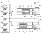
- the liquid delivery apparatus 1 includes two plunger pumps, ie, a primary pump 2 and a secondary pump 22.
- the primary pump 2 and the secondary pump 22 are connected in series with each other.
- the primary side pump 2 and the secondary side pump 22 constitute a pump unit for feeding the liquid through the discharge flow path 38.
- the primary side pump 2 includes a pump head 3 having a pump chamber 4 therein and a pump body 6.
- the pump head 3 is provided at the tip of the pump body 6.
- the pump head 3 is provided with an inlet for introducing the liquid into the pump chamber 4 and an outlet for discharging the liquid from the pump chamber 4.
- a check valve 16 is provided at the inlet of the pump head 3 to prevent backflow of the liquid.
- the distal end of the plunger 10 is slidably inserted into the pump chamber 4.
- the proximal end of the plunger 10 is held by a crosshead 8 housed within the pump body 6.
- the crosshead 8 is moved in one direction (left and right direction in the drawing) in the pump body 6 by the rotation of the feed screw 14, and the plunger 10 is moved in one direction accordingly.
- a primary pump drive motor 12 is provided to rotate the feed screw 14.
- the primary side pump drive motor 12 is a stepping motor.
- the secondary side pump 22 includes a pump head 23 having a pump chamber 24 therein, and a pump body 28.
- the pump head 23 is provided at the tip of the pump body 28.
- the pump head 23 is provided with an inlet portion for introducing the liquid into the pump chamber 24 and an outlet portion for discharging the liquid from the pump chamber 24.
- a check valve 26 is provided at the inlet of the pump head 23 to prevent backflow of the liquid.
- the tip of the plunger 32 is slidably inserted into the pump chamber 24.
- the proximal end of the plunger 32 is held by a crosshead 30 housed within the pump body 28.
- the crosshead 30 is moved in one direction (left and right direction in the drawing) in the pump body 28 by the rotation of the feed screw 36, and the plunger 32 is moved in one direction accordingly.
- a secondary pump drive motor 34 for rotating the feed screw 36 is provided at the proximal end of the pump body 28 .
- the secondary pump drive motor 34 is a stepping motor.
- the inlet of the pump head 3 is connected to a container (not shown) for storing the liquid to be fed via a flow path.
- the inlet of the pump head 23 is connected to the outlet of the pump head 3 via the connection channel 18.
- a primary side pressure sensor 20 for detecting the pressure (P1) in the pump chamber 4 is provided on the connection flow passage 18.
- the primary side pressure sensor 20 is for detecting the pressure in the pump chamber 4 of the primary side pump 2 during a non-discharge time during which the primary pump 2 is not in the discharge stroke as a non-discharge pressure.
- a discharge flow path 38 is connected to the outlet of the pump head 23.
- the discharge channel 38 communicates with, for example, an analysis channel of a liquid chromatograph.
- a secondary pressure sensor 40 for detecting the pressure (P2) in the pump chamber 24 as the liquid transfer pressure is provided on the discharge flow path 38.
- the operations of the primary pump drive motor 12 and the secondary pump drive motor 34 are controlled by the control unit 42.
- the control unit 42 is configured to cause the primary pump 2 and the secondary pump 22 to operate complementarily so that the flow rate of the liquid fed through the discharge flow path 38 becomes a preset target flow rate. There is.
- the complementary operation of the primary side pump 2 and the secondary side pump 22 will be described. While the primary side pump 2 is performing the discharge stroke for discharging the liquid, the secondary side pump 22 sucks the liquid. And a part of the liquid discharged from the primary pump 2 is sucked into the pump chamber 24 of the secondary pump 22. When the suction stroke of the secondary pump 22 is completed, the secondary pump 2 shifts to the discharge stroke. At this time, the primary side pump 2 shifts to the suction stroke, and after the suction stroke is completed, the preload stroke is performed.
- the check valve 26 is in a closed state.
- the communication between the pump chamber 4 of the primary pump 2 and the discharge flow path 38 is cut off.
- a pump in which communication with the discharge flow path 38 is interrupted during non-discharge time is referred to herein as a closed pump. Since the liquid delivery apparatus of this embodiment is an in-line double plunger system, only the primary side pump 2 corresponds to a closed pump, but in the case of a parallel double plunger system, both plunger pumps correspond to a closed pump.
- the control unit 42 is configured to control the operation of the primary-side pump drive motor 12 based on the non-discharge pressure P1 and the liquid feeding pressure P2 in the pre-compression stroke described later.
- the control unit 42 includes a preload stroke execution unit 44, a discharge speed calculation unit 46, and a discharge operation control unit 48.
- the control unit 42 includes, for example, a computer circuit having an arithmetic element such as a microcomputer and a program executed in the computer circuit, and includes a preload stroke execution unit 44, a discharge speed calculation unit 46, and a discharge operation control unit 48. Is a function obtained by the arithmetic element of the control unit 42 executing a predetermined program.
- the preload stroke execution unit 44 executes the preload stroke to the primary pump 2 after the suction stroke for sucking the liquid into the pump chamber 4 is completed during the non-discharge time when the primary pump 2 is not in the discharge stroke.
- the precompression stroke is the timing before the primary pump 2 that completed the suction stroke shifts to the discharge stroke, and the primary pump 2 is discharged until the non-discharge pressure P1 becomes approximately the same pressure as the liquid delivery pressure P2. It is a process that The timing at which the primary side pump 2 starts the preload stroke is, for example, immediately after the suction stroke of the primary side pump 2 is completed.
- the pre-discharge stroke is performed using the non-discharge pressure P1 detected by the primary side pressure sensor 20
- the present invention is not limited to this, and the primary side pressure sensor 20 may be used.
- the present invention can also be applied to a liquid delivery apparatus that is not provided.
- the preloading stroke execution unit 44 first carries out the preloading stroke by discharging the primary side pump 2 by a predetermined amount. In the discharge stroke of the primary pump 2 immediately after that, constant pressure feedback control is performed such that the liquid delivery pressure P2 detected by the secondary pressure sensor 40 becomes constant, as the operation of the primary pump 2.
- the pre-load of the immediately preceding primary side pump 2 is insufficient, a negative pulsation occurs in the fluid delivery pressure P2, so the speed of the discharge operation of the primary side pump 2 is increased.
- the pre-load of the immediately preceding primary side pump 2 is excessive, a positive pulsation occurs in the liquid delivery pressure P2, so the speed of the discharge operation of the primary side pump 2 is reduced.
- the correction pattern of the operating speed of the primary side pump 2 is stored and reflected in the preload stroke of the next cycle, so that the pressure in the pump chamber 4 of the primary side pump 2 in the preload stroke is repeated while repeating the cycle.
- the pressure can be made substantially the same as the pressure P2.
- the discharge speed calculation unit 46 calculates the volume V (pre-preload internal volume V) of the mobile phase in the pump chamber 4 immediately before the preload stroke of the primary pump 2 is started, and the movement in the pump chamber 4 reduced by the preload stroke. Calculate the optimum value of the velocity v (discharge velocity v) of the discharge operation during the discharge stroke of the primary pump 2 and the secondary pump 22 using the phase volume ⁇ V (pre-pressure volume ⁇ V) and the liquid transfer pressure P2. Is configured as.
- the optimal value of the discharge speed v is a discharge speed such that the converted value L ATM for the atmospheric pressure of the flow rate L PRE of the mobile phase discharged through the discharge flow path 38 becomes a preset flow rate L SET. .
- V ATM is the volume of fluid under atmospheric pressure.
- V PRE (1 ⁇ ⁇ P) ⁇ V ATM (1)
- L PRE is a volumetric flow rate (also referred to as a discharge flow rate) of the mobile phase discharged from the pump chamber of the plunger pump at a discharge pressure P PUMP
- L ATM is a volumetric flow rate of the mobile phase under atmospheric pressure
- L PRE plunger cross sectional area ⁇ plunger speed (3)
- L ATM L PRE / (1 ⁇ ⁇ P PUMP ) ⁇ L PRE (4)
- the above equation (4) indicates that the atmospheric pressure flow rate LATM is increased by the amount of decompression and expansion with respect to the discharge flow rate LPRE that can be controlled by the liquid delivery apparatus.
- the user of HPLC sets a desired flow rate as the analysis condition, but if the value is applied to the discharge flow rate L PRE discharged purely from the liquid transfer apparatus, the atmospheric pressure flow rate L ATM is higher than the set flow rate L SET. It is observed as an increased value.
- vendor or a user may implement a validation of measuring the deviation between the set flow rate L SET and atmospheric pressure flow L ATM.
- there is a divergence between the two which is an obstacle to determining the result of the validation even though it can not be said that it originates from the failure of the liquid delivery device itself.
- Adiabatic compression ratio ⁇ isothermal compression ratio (6) Known as a relationship. That is, the compression rate is dependent on the preload time, which also becomes an obstacle to preparing an accurate compression rate in advance.
- V is the volume of the mobile phase in the pump chamber 4 immediately before the start of the preload stroke (internal volume of the pump chamber 4)
- V PRE is the volume of the mobile phase in the pump chamber 4 immediately after the preload stroke is completed ( Internal volume of the pump chamber 4).
- P 1 is the pressure in the pump chamber 4.
- V PRE (1 ⁇ ⁇ P1) ⁇ V (7)
- the internal volume of the pump chamber 4 refers to the check valve 16 on the inlet side of the primary pump 2 and the non-return valve on the inlet side of the secondary pump 22 in the case of an in-line double plunger pump as in this embodiment.
- the volume in the system between the valves 20 is meant. Also, in the case of a parallel side double plunger pump, it means the volume in the system between the check valve on the inlet side of one pump and the check valve on the outlet side.
- the discharge flow rate L PRE can be obtained such that the flow rate L ATM of the mobile phase at atmospheric pressure becomes the set flow rate L SET . That is, in terms of value L ATM for atmospheric pressure in the discharge passage L PRE is set flow rate L SET.
- the discharge speed calculation unit 46 of the control unit 42 calculates the discharge flow rate L PRE using the above equation (11), and the flow rate of the mobile phase discharged through the discharge flow path 38 corresponds to the discharge flow rate L PRE .
- the driving speed (dispensing speed) v of the plunger 10, 32 of each pump 2, 22 as described above is determined.
- the discharge operation control unit 48 drives the plungers 10 and 32 at the driving speed v determined by the discharge speed calculation unit 46.
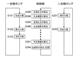
- FIG. 2 is a flow chart showing an example of the liquid feeding operation of the liquid feeding apparatus 1.
- the primary pump 2 and the secondary pump 22 operate in a complementary manner, and the secondary pump 22 performs a suction stroke while the primary pump 2 is performing a discharge stroke.
- the operation is performed (steps S101 and S201), and when the secondary pump 22 is performing the discharge stroke, the primary pump 2 executes the suction stroke and the preload stroke (steps S102, S103 and S202).
- the discharge speed calculation unit 46 of the control unit 42 determines the compression volume ⁇ V based on the driving amount of the plunger 10 during the compression stroke (step S301), and the compression volume ⁇ V
- the discharge flow rate L PRE is calculated by applying the above equation (11) to the equation (11) (step 302). Then, the discharge velocity calculating unit 46, the driving speed (discharging speed) of the plunger 10 and 32 of the discharge passage 38 discharge flow rate L PRE become each such pumps 2 and 22 the flow rate of the mobile phase was calculated to be ejected through v Decide.
- the discharge operation control unit 48 controls the plungers of the pumps 2 and 22 at the discharge speed v determined by the discharge speed calculation unit 46 in the next discharge stroke (steps S101 and S202) of the primary pump 2 and the secondary pump 22. Discharge drive 10 and 32.
- the sending pressure P2 may change during the analysis due to the change of the mobile phase composition or the like.
- the discharge speed v determined by the above-described operation is fixed without being recalculated at least until the pre-compression stroke (step S103) of the next primary side pump 2 is performed. Therefore, when the liquid feed pressure P2 between the preload stroke and the next preload stroke varies greatly, there is a possibility that the volume flow rate L ATM at atmospheric pressure of the mobile phase will deviate from the set flow rate L SET. In such a case, when the flow ratio of one of the high pressure gradient pumps is small, or when the set flow rate is very small as in a so-called micro / nano LC, the pump cycle becomes longer than the analysis time. It is easy to occur.
- the discharge speed calculation unit 46 may be configured to recalculate the discharge speed v of each of the pumps 2 and 22 following the change of the discharge pressure P2.
- a preferred embodiment of the discharge speed calculation unit 46 configured as described above will be described using the flowchart of FIG. 3.
- the discharge speed calculation unit 46 calculates the compression volume ⁇ V (step S301), and uses the compression volume ⁇ V and the discharge pressure P2 at the completion of the compression stroke.
- the compression ratio ⁇ is obtained (step S304).
- the compression ratio ⁇ obtained here is stored in a storage area provided in the control unit 42.
- the fluid delivery pressure P2 is taken into the control unit 42 at regular intervals (step S305).
- the discharge speed calculation unit 46 applies the stored compression ratio ⁇ and the latest liquid transfer pressure P2 to the following expression (13), which is equivalent to the above expression (5), every time the liquid transfer pressure P2 is taken.
- the discharge flow rate L PRE is determined, and the discharge speed v of each of the pumps 2 and 22 is determined based on the discharge flow rate L PRE (step S306).
- L PRE (1 ⁇ ⁇ P2) ⁇ L SET (13)
- the discharge operation control unit 48 adjusts the discharge speed of the pump 2 or 22 during the discharge stroke to the recalculated speed v each time the discharge speed calculation unit 46 recalculates the discharge speed of the pumps 2 and 22. As a result, even when the liquid transfer pressure P2 changes during liquid transfer, the discharge speed of the pumps 2 and 22 can be recalculated to an optimal value following the change.
- the compression ratio ⁇ is updated for each cycle of the primary side pump preload stroke (S103).
- a value based on the mechanical design of the primary side pump 2 is used as the internal volume V of the pump chamber 4 before starting the preload stroke.
- the actual internal volume of the pump chamber 4 may deviate from the design value due to processing errors of the respective parts. Therefore, the function of calculating the actual internal volume V of the pump chamber 4 may be provided to the liquid delivery apparatus 1.
- an internal volume calculation unit 50 and an internal volume storage unit 52 can be provided as a function of the control unit 42.
- the internal volume V before starting the pre-compression stroke can be expressed by the following equation (14) obtained by modifying the equation (9) described above.
- V ⁇ V / ( ⁇ ⁇ P2) (14)
- the preload volume ⁇ V can be determined by the driving distance of the plunger 10 during the preload operation, and the fluid delivery pressure P2 can be read from the pressure sensor 40. Therefore, by using the mobile phase whose compression ratio ⁇ is known, the internal volume V before starting the pre-compression stroke can be determined.
- the internal volume calculation unit 50 acquires the preload volume ⁇ V and the delivery pressure P2 in the preload stroke of the primary side pump 2 when the mobile phase (for example, water) having a known compression ratio ⁇ is known, It applies to (14) and it is comprised so that the internal volume V may be calculated
- the internal volume storage unit 52 is a storage area for storing the value of the internal volume V calculated by the internal volume calculation unit 50.
- the discharge speed calculation unit 46 is configured to calculate the discharge speed of each pump 2 using the value of the internal volume V stored in the internal volume storage unit 52. Thereby, the discharge speed of each pump 2 can be determined using the value of the exact internal volume V, and the accuracy of the liquid transfer flow rate can be improved.
- calculation of the discharge speed v of each of the pumps 2 and 22 and calculation of the compression ratio ⁇ are performed each time the pre-compression stroke of the primary side pump 2 is completed.
- filtering such as moving average may be applied to the calculation results of several cycles of the pump.
- the calculation of the compression rate ⁇ and the calculation of the discharge speed v may be performed once, and thereafter, the calculated value may be fixed and applied.
- the embodiment of the present invention has been described based on the state in which the mobile phase is continuously discharged to the downstream of the liquid delivery apparatus 1.
- the discharge flow path 38 is sealed using valve means or the like.
- the compression rate ⁇ may be determined and stored by feeding the liquid in the above state, and the discharge rate v may be determined using the compression rate ⁇ in actual analysis.
Landscapes
- Engineering & Computer Science (AREA)
- General Engineering & Computer Science (AREA)
- Mechanical Engineering (AREA)
- Chemical & Material Sciences (AREA)
- Analytical Chemistry (AREA)
- Biochemistry (AREA)
- General Health & Medical Sciences (AREA)
- General Physics & Mathematics (AREA)
- Immunology (AREA)
- Pathology (AREA)
- Physics & Mathematics (AREA)
- Life Sciences & Earth Sciences (AREA)
- Health & Medical Sciences (AREA)
- Chemical Kinetics & Catalysis (AREA)
- Computer Hardware Design (AREA)
- Control Of Positive-Displacement Pumps (AREA)
- Details Of Reciprocating Pumps (AREA)
Abstract
La présente invention concerne un dispositif de distribution de liquide qui est pourvu de : une unité de calcul de taux d'évacuation configurée pour utiliser le volume V d'une phase mobile à l'intérieur d'une chambre de pompe d'une pompe fermée juste avant de démarrer une course de précompression, le volume ΔV de la phase mobile à l'intérieur de la chambre de pompe de la pompe fermée après avoir été diminué par la course de précompression, et une pression de distribution de liquide P, et obtenir un taux d'évacuation de pompe à piston v auquel une valeur de conversion LATM, sous pression atmosphérique, du débit LPRE de la phase mobile évacuée vers un passage d'écoulement d'évacuation depuis une unité de pompe devient un débit de consigne LSET ; et une unité de commande d'opération d'évacuation configurée pour actionner la pompe à piston au taux de décharge v obtenu par l'unité de calcul de taux d'évacuation.
Priority Applications (4)
| Application Number | Priority Date | Filing Date | Title |
|---|---|---|---|
| PCT/JP2017/038208 WO2019082243A1 (fr) | 2017-10-23 | 2017-10-23 | Dispositif de distribution de liquide et chromatographe fluidique |
| CN201780092525.4A CN110809713B (zh) | 2017-10-23 | 2017-10-23 | 送液装置及流体色谱仪 |
| US16/648,077 US11307179B2 (en) | 2017-10-23 | 2017-10-23 | Liquid feeding device and fluid chromatograph |
| JP2019549691A JP6849095B2 (ja) | 2017-10-23 | 2017-10-23 | 送液装置及び流体クロマトグラフ |
Applications Claiming Priority (1)
| Application Number | Priority Date | Filing Date | Title |
|---|---|---|---|
| PCT/JP2017/038208 WO2019082243A1 (fr) | 2017-10-23 | 2017-10-23 | Dispositif de distribution de liquide et chromatographe fluidique |
Publications (1)
| Publication Number | Publication Date |
|---|---|
| WO2019082243A1 true WO2019082243A1 (fr) | 2019-05-02 |
Family
ID=66246286
Family Applications (1)
| Application Number | Title | Priority Date | Filing Date |
|---|---|---|---|
| PCT/JP2017/038208 Ceased WO2019082243A1 (fr) | 2017-10-23 | 2017-10-23 | Dispositif de distribution de liquide et chromatographe fluidique |
Country Status (4)
| Country | Link |
|---|---|
| US (1) | US11307179B2 (fr) |
| JP (1) | JP6849095B2 (fr) |
| CN (1) | CN110809713B (fr) |
| WO (1) | WO2019082243A1 (fr) |
Cited By (5)
| Publication number | Priority date | Publication date | Assignee | Title |
|---|---|---|---|---|
| CN110794069A (zh) * | 2019-10-08 | 2020-02-14 | 北京卫星制造厂有限公司 | 基于微升级体积有机溶剂液体压缩率在线测试方法及系统 |
| CN115569620A (zh) * | 2022-10-31 | 2023-01-06 | 浙江硕而博化工有限公司 | 一种连续化碳酸乙烯酯的光氯化反应的生产工艺 |
| WO2023127327A1 (fr) * | 2021-12-28 | 2023-07-06 | 株式会社日立ハイテク | Pompe de distribution de liquide |
| WO2023203881A1 (fr) | 2022-04-19 | 2023-10-26 | 株式会社日立ハイテク | Pompe d'alimentation en liquide et procédé d'alimentation en liquide |
| US12467908B2 (en) | 2020-11-19 | 2025-11-11 | Hitachi High-Tech Corporation | Liquid feeding pump and liquid feeding method |
Families Citing this family (7)
| Publication number | Priority date | Publication date | Assignee | Title |
|---|---|---|---|---|
| JP7307271B2 (ja) * | 2020-03-24 | 2023-07-11 | 株式会社日立ハイテク | 送液装置および送液方法 |
| EP3991820A1 (fr) * | 2020-11-03 | 2022-05-04 | Sartorius Stedim Biotech GmbH | Système de chromatographie à membrane |
| CN114135460B (zh) * | 2021-12-15 | 2024-01-26 | 大连依利特分析仪器有限公司 | 一种直驱型高压恒流泵装置及控制方法 |
| JP7771803B2 (ja) * | 2022-02-14 | 2025-11-18 | 株式会社島津製作所 | 液体クロマトグラフ |
| CN114910215B (zh) * | 2022-05-18 | 2024-05-14 | 杭州谱育科技发展有限公司 | 液体输送装置和液相色谱仪的校正方法 |
| AU2023277540A1 (en) * | 2022-05-26 | 2024-12-05 | Schwing Bioset, Inc. | Continuous flow multi-piston pump |
| EP4524396A1 (fr) * | 2023-09-12 | 2025-03-19 | Airbus Operations GmbH | Système hydraulique pour véhicule, tel qu'un aéronef |
Citations (8)
| Publication number | Priority date | Publication date | Assignee | Title |
|---|---|---|---|---|
| JPH0772130A (ja) * | 1993-03-05 | 1995-03-17 | Waters Investments Ltd | 溶剤ポンプ送り装置 |
| JPH07119627A (ja) * | 1993-10-29 | 1995-05-09 | Nikkiso Co Ltd | 無脈動ポンプの脈動調整機構 |
| JPH08114177A (ja) * | 1994-08-23 | 1996-05-07 | Nikkiso Co Ltd | 無脈動ポンプ |
| JP2005156218A (ja) * | 2003-11-21 | 2005-06-16 | Shimadzu Corp | 送液装置 |
| JP2007327449A (ja) * | 2006-06-09 | 2007-12-20 | Nikkiso Co Ltd | 無脈動ポンプ |
| WO2012014741A1 (fr) * | 2010-07-29 | 2012-02-02 | 株式会社日立ハイテクノロジーズ | Pompe pour chromatographe en phase liquide, et chromatographe en phase liquide |
| JP2013119800A (ja) * | 2011-12-07 | 2013-06-17 | Tosoh Corp | プランジャポンプ |
| US9360006B2 (en) * | 2009-04-29 | 2016-06-07 | Agilent Technologies, Inc. | Primary piston correction during transfer |
Family Cites Families (13)
| Publication number | Priority date | Publication date | Assignee | Title |
|---|---|---|---|---|
| CN1003396B (zh) * | 1985-04-01 | 1989-02-22 | 株式会社岛津制作所 | 液相色谱分析仪 |
| GB2195473B (en) * | 1986-09-17 | 1990-08-15 | Philips Electronic Associated | Liquid chromatograph |
| JPS63173866A (ja) * | 1987-01-09 | 1988-07-18 | Hitachi Ltd | 無脈動ポンプの制御方式 |
| JP4480808B2 (ja) * | 1999-03-19 | 2010-06-16 | ジーエルサイエンス株式会社 | 液体クロマトグラフ等の送液方法及び装置 |
| GB2428073B (en) * | 2004-03-05 | 2009-02-25 | Waters Investments Ltd | Device and methods of measuring pressure in a pump for use in liquid chromatography |
| JP4709629B2 (ja) * | 2005-10-19 | 2011-06-22 | 株式会社日立ハイテクノロジーズ | ポンプ装置 |
| EP2000790B1 (fr) * | 2006-03-29 | 2012-09-12 | JMS Co., Ltd. | Dispositif de detection de la pression |
| EP1785623B1 (fr) * | 2006-10-25 | 2009-05-06 | Agilent Technologies, Inc. | Appareil de pompage avec différence de phases variable entre les pistons de pompage |
| JP2008215978A (ja) * | 2007-03-02 | 2008-09-18 | Shimadzu Corp | 送液ポンプ及びそれを用いた液体クロマトグラフ |
| US9551625B2 (en) * | 2011-05-31 | 2017-01-24 | Nxstage Medical, Inc. | Pressure measurement devices, methods, and systems |
| CN108291897B (zh) * | 2015-11-26 | 2021-04-09 | 株式会社岛津制作所 | 送液装置、送液装置的送液控制方法以及送液装置的送液控制程序 |
| JP6439881B2 (ja) * | 2015-12-01 | 2018-12-19 | 株式会社島津製作所 | 送液装置 |
| CN110799754B (zh) * | 2017-07-28 | 2020-12-29 | 株式会社岛津制作所 | 送液装置 |
-
2017
- 2017-10-23 US US16/648,077 patent/US11307179B2/en active Active
- 2017-10-23 JP JP2019549691A patent/JP6849095B2/ja active Active
- 2017-10-23 CN CN201780092525.4A patent/CN110809713B/zh active Active
- 2017-10-23 WO PCT/JP2017/038208 patent/WO2019082243A1/fr not_active Ceased
Patent Citations (8)
| Publication number | Priority date | Publication date | Assignee | Title |
|---|---|---|---|---|
| JPH0772130A (ja) * | 1993-03-05 | 1995-03-17 | Waters Investments Ltd | 溶剤ポンプ送り装置 |
| JPH07119627A (ja) * | 1993-10-29 | 1995-05-09 | Nikkiso Co Ltd | 無脈動ポンプの脈動調整機構 |
| JPH08114177A (ja) * | 1994-08-23 | 1996-05-07 | Nikkiso Co Ltd | 無脈動ポンプ |
| JP2005156218A (ja) * | 2003-11-21 | 2005-06-16 | Shimadzu Corp | 送液装置 |
| JP2007327449A (ja) * | 2006-06-09 | 2007-12-20 | Nikkiso Co Ltd | 無脈動ポンプ |
| US9360006B2 (en) * | 2009-04-29 | 2016-06-07 | Agilent Technologies, Inc. | Primary piston correction during transfer |
| WO2012014741A1 (fr) * | 2010-07-29 | 2012-02-02 | 株式会社日立ハイテクノロジーズ | Pompe pour chromatographe en phase liquide, et chromatographe en phase liquide |
| JP2013119800A (ja) * | 2011-12-07 | 2013-06-17 | Tosoh Corp | プランジャポンプ |
Cited By (12)
| Publication number | Priority date | Publication date | Assignee | Title |
|---|---|---|---|---|
| CN110794069A (zh) * | 2019-10-08 | 2020-02-14 | 北京卫星制造厂有限公司 | 基于微升级体积有机溶剂液体压缩率在线测试方法及系统 |
| US12467908B2 (en) | 2020-11-19 | 2025-11-11 | Hitachi High-Tech Corporation | Liquid feeding pump and liquid feeding method |
| WO2023127327A1 (fr) * | 2021-12-28 | 2023-07-06 | 株式会社日立ハイテク | Pompe de distribution de liquide |
| JP2023097906A (ja) * | 2021-12-28 | 2023-07-10 | 株式会社日立ハイテク | 送液ポンプ |
| JP7675644B2 (ja) | 2021-12-28 | 2025-05-13 | 株式会社日立ハイテク | 送液ポンプ |
| EP4459276A4 (fr) * | 2021-12-28 | 2025-06-18 | Hitachi High-Tech Corporation | Pompe de distribution de liquide |
| US12546299B2 (en) | 2021-12-28 | 2026-02-10 | Hitachi High-Tech Corporation | Liquid delivery pump |
| WO2023203881A1 (fr) | 2022-04-19 | 2023-10-26 | 株式会社日立ハイテク | Pompe d'alimentation en liquide et procédé d'alimentation en liquide |
| JP2023158680A (ja) * | 2022-04-19 | 2023-10-31 | 株式会社日立ハイテク | 送液ポンプ及び送液方法 |
| JP7756594B2 (ja) | 2022-04-19 | 2025-10-20 | 株式会社日立ハイテク | 送液ポンプ及び送液方法 |
| EP4513035A4 (fr) * | 2022-04-19 | 2026-02-18 | Hitachi High Tech Corp | Pompe d'alimentation en liquide et procédé d'alimentation en liquide |
| CN115569620A (zh) * | 2022-10-31 | 2023-01-06 | 浙江硕而博化工有限公司 | 一种连续化碳酸乙烯酯的光氯化反应的生产工艺 |
Also Published As
| Publication number | Publication date |
|---|---|
| CN110809713B (zh) | 2022-06-21 |
| JP6849095B2 (ja) | 2021-03-24 |
| JPWO2019082243A1 (ja) | 2020-04-02 |
| CN110809713A (zh) | 2020-02-18 |
| US11307179B2 (en) | 2022-04-19 |
| US20200278329A1 (en) | 2020-09-03 |
Similar Documents
| Publication | Publication Date | Title |
|---|---|---|
| WO2019082243A1 (fr) | Dispositif de distribution de liquide et chromatographe fluidique | |
| JP4887295B2 (ja) | 流れを補償するポンプと注入器の同期のための装置、システム、および方法 | |
| CN108291897B (zh) | 送液装置、送液装置的送液控制方法以及送液装置的送液控制程序 | |
| WO2018198234A1 (fr) | Dispositif d'alimentation en liquide et chromatographe en phase fluide | |
| JP7123968B2 (ja) | 医療流体のための容積式ポンプおよび医療流体のための容積式ポンプを備える血液処理装置ならびに医療流体のための容積式ポンプを制御するための方法 | |
| WO2019021475A1 (fr) | Dispositif d'alimentation en liquide | |
| GB2446321A (en) | Flow control for chromatography high pressure pump. | |
| JP2009053098A (ja) | 送液装置、液体クロマトグラフ、および送液装置の運転方法 | |
| JP2014215125A (ja) | 高圧力定流量ポンプ及び高圧力定流量送液方法 | |
| JP6780780B2 (ja) | 送液装置 | |
| JP6439881B2 (ja) | 送液装置 | |
| US20240408301A1 (en) | System and method for fluid delivery using pressure-based motor control for fluid injector devices | |
| JP3508378B2 (ja) | 液体加圧装置 | |
| CN113892030B (zh) | 送液泵及液相色谱仪 | |
| CN113795673B (zh) | 二元泵及液相色谱仪 | |
| JP2008019823A (ja) | 液体定量送り装置の制御方法 |
Legal Events
| Date | Code | Title | Description |
|---|---|---|---|
| 121 | Ep: the epo has been informed by wipo that ep was designated in this application |
Ref document number: 17929870 Country of ref document: EP Kind code of ref document: A1 |
|
| ENP | Entry into the national phase |
Ref document number: 2019549691 Country of ref document: JP Kind code of ref document: A |
|
| NENP | Non-entry into the national phase |
Ref country code: DE |
|
| 122 | Ep: pct application non-entry in european phase |
Ref document number: 17929870 Country of ref document: EP Kind code of ref document: A1 |