WO2019087267A1 - 空気圧式アクチュエータ - Google Patents
空気圧式アクチュエータ Download PDFInfo
- Publication number
- WO2019087267A1 WO2019087267A1 PCT/JP2017/039200 JP2017039200W WO2019087267A1 WO 2019087267 A1 WO2019087267 A1 WO 2019087267A1 JP 2017039200 W JP2017039200 W JP 2017039200W WO 2019087267 A1 WO2019087267 A1 WO 2019087267A1
- Authority
- WO
- WIPO (PCT)
- Prior art keywords
- sleeve
- cord
- constituting
- actuator
- cords
- Prior art date
- Legal status (The legal status is an assumption and is not a legal conclusion. Google has not performed a legal analysis and makes no representation as to the accuracy of the status listed.)
- Ceased
Links
Images







Classifications
-
- F—MECHANICAL ENGINEERING; LIGHTING; HEATING; WEAPONS; BLASTING
- F15—FLUID-PRESSURE ACTUATORS; HYDRAULICS OR PNEUMATICS IN GENERAL
- F15B—SYSTEMS ACTING BY MEANS OF FLUIDS IN GENERAL; FLUID-PRESSURE ACTUATORS, e.g. SERVOMOTORS; DETAILS OF FLUID-PRESSURE SYSTEMS, NOT OTHERWISE PROVIDED FOR
- F15B15/00—Fluid-actuated devices for displacing a member from one position to another; Gearing associated therewith
- F15B15/08—Characterised by the construction of the motor unit
- F15B15/10—Characterised by the construction of the motor unit the motor being of diaphragm type
- F15B15/103—Characterised by the construction of the motor unit the motor being of diaphragm type using inflatable bodies that contract when fluid pressure is applied, e.g. pneumatic artificial muscles or McKibben-type actuators
-
- F—MECHANICAL ENGINEERING; LIGHTING; HEATING; WEAPONS; BLASTING
- F15—FLUID-PRESSURE ACTUATORS; HYDRAULICS OR PNEUMATICS IN GENERAL
- F15B—SYSTEMS ACTING BY MEANS OF FLUIDS IN GENERAL; FLUID-PRESSURE ACTUATORS, e.g. SERVOMOTORS; DETAILS OF FLUID-PRESSURE SYSTEMS, NOT OTHERWISE PROVIDED FOR
- F15B15/00—Fluid-actuated devices for displacing a member from one position to another; Gearing associated therewith
- F15B15/08—Characterised by the construction of the motor unit
- F15B15/10—Characterised by the construction of the motor unit the motor being of diaphragm type
Definitions
- the present invention relates to a pneumatic actuator.
- an air pressure having a rubber tube (tubular body) that inflates and contracts using air as a working fluid and a sleeve (mesh reinforcing structure) covering the outer circumferential surface of the tube
- An actuator so-called Mackben type
- Mackben type is widely used (see, for example, Patent Document 1).
- Both ends of the actuator body constituted by the tube and the sleeve are crimped using a sealing member formed of metal.
- the sleeve is a tubular structure in which a high tension fiber such as polyamide fiber or a metal cord is woven, and regulates the expansion movement of the tube within a predetermined range.
- Such a pneumatic actuator is used in various fields, but is particularly suitably used as an artificial muscle of a care and welfare device.
- the above-mentioned conventional actuators do not necessarily have high strength (pressure resistance), and in particular, when the sleeve is not properly designed, the load on the tube becomes large, and there is room for improvement in durability.
- this invention solves the problem of the said prior art, and makes it a subject to provide the pneumatic actuator which improved durability in the actuator which uses gas as a working fluid.
- the gist configuration of the present invention for solving the above problems is as follows.
- the pneumatic actuator of the present invention is constituted by a tubular tube which is expanded and contracted by air pressure, and a tubular structure in which a cord oriented in a predetermined direction is woven and which covers the outer peripheral surface of the tube.
- An actuator body that is In the no load and no pressure state, the average angle of the cords forming the sleeve with respect to the axial direction of the actuator is 20 degrees or more and less than 45 degrees, In a state where the average angle of the cords constituting the sleeve with respect to the axial direction of the actuator is 45 degrees at an air pressure of 5 MPa, the total of the gaps of the cords constituting the sleeve with respect to the area (S1) of the outer surface of the actuator main body It is characterized in that the ratio (S2 / S1) of the area (S2) is 35% or less.
- Such a pneumatic actuator of the present invention has a small load on the tube and improved durability because the sleeve is properly designed.
- the cord constituting the sleeve is made of at least one fiber material selected from polyamide fiber, polyester fiber, polyurethane fiber, rayon, acrylic fiber and polyolefin fiber. In this case, the durability of the actuator is further improved.
- a cord group oriented in one direction and a cord group intersecting with each other are alternated with two or one cord of each cord group. , And the positions at which they cross each other are shifted one by one. In this case, the durability of the actuator is further improved.
- the sleeve is formed by twill weave or plain weave of the cord. Also in this case, the durability of the actuator is further improved.
- the breaking strength of the cord constituting the sleeve is 200 N / cord or more. In this case, the durability of the actuator is further improved. In the present invention, the breaking strength of the cord is measured in accordance with JIS L1017.
- the breaking elongation of the cord constituting the sleeve is 2.0% or more. In this case, the durability of the actuator is further improved. In the present invention, the breaking elongation of the cord is measured in accordance with JIS L1017.
- the thickness of the cord constituting the sleeve is 0.3 mm to 1.5 mm. In this case, the durability of the actuator is further improved.
- the implantation density of the cords constituting the sleeve is 6.8 cords / cm to 25.5 cords / cm. In this case, the durability of the actuator is further improved.
- the sleeve has a thickness t (mm) of the tube, a thickness d (mm) of a cord constituting the sleeve, and the sleeve under no load and no pressure.
- the average angle ⁇ 2 of the cords constituting the sleeve at the time of contraction of the actuator with respect to the axial direction of the actuator is a value measured with a load of 2.5 kN and an air pressure of 5 MPa.
- the thickness t (mm) of the tube, the thickness d (mm) of the cord constituting the sleeve, and in the no load and no pressure state, the cord constituting the sleeve has an average in the axial direction of the actuator.
- the angle ⁇ 1 and the average angle ⁇ 2 of the cords constituting the sleeve with respect to the axial direction of the actuator at the time of contraction of the actuator are expressed by the following formula (2) It is further preferable that In this case, the durability of the actuator is further improved.
- the cord constituting the sleeve has the following formula (3): [Wherein, T 2 is the number of twists of the cord (count / 10 cm), provided that the cord has a single-twist structure, the number of twist T 2 (count / 10 cm) is the number of twist T 1 (count / 10 cm) And D is the fineness (dtex) per yarn of the yarn constituting the cord, and ⁇ is the density of the yarn constituting the cord (g / cm 3 ) The coefficient K is 0.14 to 0.50. In this case, since the sleeve is properly designed, the load on the tube is reduced and the durability of the actuator is further improved.
- the cord constituting the sleeve has a ratio (T 1 ) between the number of first twist T 1 (times / 10 cm) and the fineness D (dtex) per one of the raw yarns constituting the cord. It is preferable that / D) be 0.004 to 0.03. In this case, the durability of the actuator is further improved.
- the cord constituting the sleeve has a ratio (T 1 / T 2 ) of the number of first twist T 1 (twice / 10 cm) to the number of upper twist T 2 (twice / 10 cm) is 0. It is preferably 8 to 1.2. In this case, the durability of the actuator is further improved.
- the fineness D of one per yarn constituting the code is 800 ⁇ 5000dtex
- the number of first twists T 1 is 3.2 to 150 times /
- the number of twists is preferably 10 cm
- the number of upper twists T 2 is 2.6 to 180 times / 10 cm
- the number of twists is 2 to 4. In this case, the durability of the actuator is further improved.
- the thickness of the tube is 1.0 mm to 6.0 mm under no load and no pressure. In this case, the durability of the actuator is further improved.
- a pneumatic actuator with improved durability can be provided.
- FIG. 1 is a side view of one embodiment of a pneumatic actuator 10.
- FIG. FIG. 1 is a partially exploded perspective view of an embodiment of a pneumatic actuator 10.
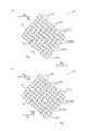
- FIG. 7A is a partial side view of two embodiments of the sleeve 120 in a no load and no pressure condition.
- FIG. 7A is a partial side view of two embodiments of the sleeve 120 with the cord 121 comprising the sleeve 120 at an average angle of 45 degrees to the axial direction of the actuator.
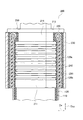
- FIG. 10 is a partial cross-sectional view along an axial direction D AX of a pneumatic actuator 10 including a sealing mechanism 200 according to Embodiment 1-1.
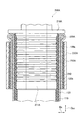
- FIG. 7 is a partial cross-sectional view along an axial direction D AX of a pneumatic actuator 10 including a sealing mechanism 200 according to Embodiment 1-2.
- FIG. 10 is a partial cross-sectional view along an axial direction D AX of a pneumatic actuator 10 including a sealing mechanism 200 according to Embodiment 1-3.
- FIG. 21 is a partial cross-sectional view of the pneumatic actuator 10 including the sealing mechanism 200A according to Embodiment 2-1 along the axial direction D AX .
- FIG. 21 is a partial cross-sectional view of the pneumatic actuator 10 including the sealing mechanism 200A according to Embodiment 2-2 along the axial direction D AX .
- FIG. 21 is a partial cross-sectional view of the pneumatic actuator 10 including the sealing mechanism 200A according to Embodiment 2-3 along the axial direction D AX .
- FIG. 31 is a partial cross-sectional view of the pneumatic actuator 10 including the sealing mechanism 200B according to Embodiment 3-1 along the axial direction D AX .
- FIG. 31 is a partial cross-sectional view of the pneumatic actuator 10 including the sealing mechanism 200C according to Embodiment 3-2 along the axial direction D AX .
- FIG. 1 is a side view of a pneumatic actuator 10 according to the present embodiment.
- the pneumatic actuator 10 includes an actuator body 100, a sealing mechanism 200 and a sealing mechanism 300.
- the connection part 20 is provided in the both ends of the pneumatic actuator 10, respectively.
- the actuator body 100 is constituted by a tube 110 and a sleeve 120.
- the working fluid flows into the actuator body 100 through the fitting 400 and the passage hole 410.
- the actuator of the present invention is a pneumatic type, and a gas is used as a working fluid, and examples of the gas include air and nitrogen.
- Actuator body portion 100 by the working fluid into the tube 110 flows, contracts in the axial direction D AX of the actuator body portion 100 expands radially D R. Further, the actuator body portion 100, by which the working fluid flows out of the tube 110, and expands in the axial direction D AX of the actuator body portion 100, to radially contract D R. Due to such a change in the shape of the actuator body 100, the pneumatic actuator 10 exhibits a function as an actuator.
- Such a pneumatic actuator 10 is a so-called McKibben type and can be applied not only to artificial muscles, but also to the limbs (upper and lower limbs, etc.) of a robot that requires higher ability (contraction force) It can also be suitably used as
- the connecting portion 20 is connected to a member or the like that constitutes the body limb.
- the sealing mechanism 200 and the sealing mechanism 300 seal both ends of the actuator body 100 in the axial direction D AX .
- the sealing mechanism 200 includes a sealing member 210 and a caulking member 230.
- the sealing member 210 seals the end of the actuator body 100 in the axial direction D AX .
- the caulking member 230 caulks the actuator body 100 together with the sealing member 210.
- an indentation 231 is formed which is a trace of caulking of the caulking member 230 by a jig.
- the difference between the sealing mechanism 200 and the sealing mechanism 300 is that the roles of the fittings 400 and 500 (and the passage holes 410 and 510) are different.
- the fitting 400 provided in the sealing mechanism 200 protrudes so as to attach a hose (pipeline) connected to a driving pressure source of the pneumatic actuator 10, specifically, a compressor for working fluid.
- the working fluid that has flowed in via the fitting 400 passes through the passage hole 410 and flows into the inside of the actuator body 100, specifically, the inside of the tube 110.
- the fitting 500 provided in the sealing mechanism 300 protrudes so that it can be used as degassing when injecting the working fluid into the actuator.
- gas originally present inside the actuator is discharged from the fitting 500 through the passage hole 510.
- FIG. 2 is a partial exploded perspective view of the pneumatic actuator 10.
- the pneumatic actuator 10 comprises an actuator body 100 and a sealing mechanism 200.
- the actuator body 100 is configured by the tube 110 and the sleeve 120 as described above.
- the tube 110 is a cylindrical cylindrical body that expands and contracts by air pressure.
- the tube 110 is made of an elastic material such as rubber to repeat contraction and expansion by the working fluid.
- the thickness of the tube 110 is preferably in the range of 1.0 mm to 6.0 mm, and more preferably in the range of 1.4 mm to 5.0 mm.
- the thickness of the tube 110 is 1.0 mm or more, the strength of the tube 110 is improved, the protrusion of the tube 110 from the gap of the cords constituting the sleeve 120 can be suppressed, and the durability as the actuator is further improved.
- the thickness of the tube 110 is 6.0 mm or less, the contraction rate of the tube 110 becomes large, and a sufficient operation length can be secured.
- the tube 110 shown in FIG.1 and FIG.2 is 1 layer structure, in this invention, the tube may have a structure of two or more layers.
- the diameter (outer diameter) of the tube 110 can be suitably selected according to the intended application.
- the sleeve 120 is cylindrical and covers the outer circumferential surface of the tube 110.
- the sleeve 120 is a structure in which cords oriented in a predetermined direction are woven, and the rhombic shape is repeated by crossing the oriented cords. By having such a shape, the sleeve 120 is pantograph deformed and follows while restricting contraction and expansion of the tube 110.
- FIG. 3 is a partial side view of two embodiments of the sleeve 120 in a no load and no pressure condition.
- the cord 121 constituting the sleeve 120 with respect to the axial direction D AX of the actuator in the no load and no pressure state (that is, the initial state), the cord 121 constituting the sleeve 120 with respect to the axial direction D AX of the actuator.
- the average angle ⁇ 1 is 20 degrees or more and less than 45 degrees.
- the durability of the sleeve 120 is improved because the average angle ⁇ 1 of the cord 121 constituting the sleeve 120 with respect to the axial direction D AX of the actuator is 20 degrees or more.
- the average angle ⁇ 1 of the cord 121 constituting the sleeve 120 with respect to the axial direction D AX of the actuator exceeds 45 degrees in the no load and no pressure state, the contraction at the time of actuation of the actuator is small and sufficient as the actuator Not functional.
- the average angle theta 1 is preferably 22 degrees or more, more preferably 23 degrees or more. As the average angle ⁇ 1 is larger, the load on the tube 110 is smaller, the breakage of the tube 110 in the portion not in direct contact with the cord 121 is suppressed, and the function as the actuator can be maintained for a long time.
- the average angle ⁇ 1 is preferably 37 degrees or less.
- the actuator shrinkage becomes large, it with an adequate length.
- the average angle ⁇ 1 of the cords 121 constituting the sleeve 120 with respect to the axial direction D AX of the actuator adjusts, for example, the direction of the cords 121 at the time of knitting the sleeve 120. It can adjust by adjusting the direction of the cord 121 at the time of doing.
- FIG. 4 is a partial side view of two embodiments of the sleeve 120 with the cord 121 comprising the sleeve 120 at an average angle of 45 degrees with respect to the axial direction D AX of the actuator.
- ⁇ 1 degree is allowed as an error range.
- FIG. 4 shows that when measuring the angle of the cord 121, ⁇ 1 degree is allowed as an error range. In the present invention, as shown in FIG.
- the ratio (S2 / S1) of the total area (S2) of the gap 122 of the cord 121 constituting the sleeve 120 to the area (S1) of the outer surface of the actuator body 100 is 35% or less, preferably 32 % Or less, more preferably 30% or less, still more preferably 25% or less, particularly preferably 20% or less.
- the durability of the The lower limit of the ratio (S2 / S1) is not particularly limited, but the ratio (S2 / S1) is preferably 5% or more from the viewpoint of the operating length of the actuator.
- the total area (S2) of the gaps 122 of the cords 121 constituting the sleeve 120 can be adjusted by selecting the knitting method of the sleeve 120, the thickness of the cords 121 to be used, the material, the insertion density and the like.
- the total area of the gap 122 of the code 121 constituting the sleeve 120 (S2) is pneumatically 5 MPa, code 121 constituting the sleeve 120, the average angle theta 3 with respect to the axial direction D AX of the actuator 45
- the load applied to the actuator is adjusted and measured so that At that time, the diameter of the sleeve 120 is evaluated in the range up to the range of minus 5% with respect to the maximum diameter of the sleeve 120, and the total area of the gap 122 in the region is S2.
- the ratio (S2 / S1) is calculated, where the area of the outer surface is S1.
- the area of the gap 122 of the cords 121 constituting the sleeve 120 corresponds to the area where the cords 121 do not exist when the sleeve is viewed from the outside, and the tube 110 present inside is exposed.
- the average angle theta 1 with respect to the axial direction D AX of the actuator, theta 2, theta 3 refers to the acute angle side of the angle formed by the axial direction D AX code 121 and the actuator.
- cords 121 constituting the sleeve 120 polyamide fibers such as aramid fibers (aromatic polyamide fibers), polyhexamethylene adipamide (nylon 6, 6) fibers, polycaprolactam (nylon 6) fibers, etc., polyethylene terephthalate (PET) It is preferable to use a fiber cord made of at least one fiber material selected from fibers, polyester fibers such as polyethylene naphthalate (PEN) fibers, polyurethane fibers, rayon, acrylic fibers, and polyolefin fibers. In this case, the durability of the sleeve is further improved.
- PEN polyethylene naphthalate
- a cord made of aramid fiber from the viewpoint of the strength of the sleeve 120, it is particularly preferable to use a cord made of aramid fiber.
- the present invention is not limited to such a type of fiber cord, and for example, using a high strength fiber such as PBO (polyparaphenylene benzo bis oxazole) fiber or a metal cord constituted by an extra-fine filament It is also good.
- the surface of the above-mentioned fiber cord or metal cord may be coated with rubber, a mixture of thermosetting resin and latex, or the like.
- the coefficient of friction of the surface of the cord can be appropriately reduced while improving the durability of the cord.
- 15 mass% or more and 50 mass% or less are preferable, and, as for the solid fraction in the mixture of a thermosetting resin and latex, 20 mass% or more and 40 mass% or less are still more preferable.
- thermosetting resin may, for example, be a phenol resin, resorcinol resin or urethane resin
- the latex may, for example, be vinylpyridine (VP) latex, styrene-butadiene rubber (SBR) latex or acrylonitrile-butadiene rubber (NBR) latex.
- VP vinylpyridine
- SBR styrene-butadiene rubber
- NBR acrylonitrile-butadiene rubber
- a cord group 121A oriented in one direction and a cord group 121B intersecting with each other are each cord group 121A, It is preferable that two cords 121B of the cord 121 are alternately and alternately formed, and the intersecting positions are configured to be shifted by one by one, that is, they are formed by twill weave (twill weave). In this case, the load on the tube 110 is further reduced, and the durability as an actuator is further improved.
- the cord group 121A oriented in one direction and the cord group 121B intersecting with each other are each cord group
- one cord 121 of each of the cords 121A and 121B be alternately and alternately configured, that is, it be composed of a plain weave.
- the load on the tube 110 is further reduced, and the durability as the actuator is further improved.
- the sleeve 120 be formed by braiding the cord 121. Also in this case, the load on the tube 110 is further reduced, and the durability as the actuator is further improved.
- the number of cords to be aligned is not particularly limited in the case of Hashiko, in the present invention, two cords are aligned and two separate cords separately aligned are punched in. Is preferred.
- the breaking strength of the cord 121 constituting the sleeve 120 is preferably 200 N / cord or more, more preferably in the range of 250 N / cord to 1000 N / cord, more preferably in the range of 300 N / cord to 1000 N / cord. Is more preferable, the range of 500 N / piece to 1000 N / piece is still more preferable, and the range of 600 N / piece to 1000 N / piece is particularly preferable. In this case, the load on the tube 110 is further reduced, and the durability of the actuator is further improved.
- the breaking elongation of the cord 121 constituting the sleeve 120 is preferably 2.0% or more, and more preferably in the range of 3.0% to 6.0%. In this case, the load on the tube 110 is further reduced, and the durability of the actuator is further improved.
- the thickness of the cord 121 constituting the sleeve 120 is preferably 0.3 mm to 1.5 mm, more preferably 0.4 mm to 1.5 mm, and further preferably 0.5 mm to 1 It is more preferable that the diameter is 0.5 mm, still more preferably 0.6 mm to 1.3 mm, and particularly preferably 0.6 mm to 1.0 mm. In this case, the load on the tube 110 is further reduced, and the durability of the actuator is further improved.
- the implantation density of the cord 121 constituting the sleeve 120 is preferably 6.8 cords / cm to 25.5 cords / cm, and 10.0 cords / cm to 23.5 cords / cm. More preferably, it is 10.0 cords / cm to 20.0 cords / cm. In this case, the load on the tube 110 is further reduced, and the durability of the actuator is further improved.
- the thickness t (mm) of the tube 110 the thickness d (mm) of the cord 121 constituting the sleeve 120, and the cord 121 constituting the sleeve 120 in no load and no pressure state.
- the average angle ⁇ ⁇ ⁇ ⁇ 1 of the actuator with respect to the axial direction D AX and the average angle ⁇ 2 of the cord 121 constituting the sleeve 120 with respect to the axial direction D AX of the actuator at the time of contraction of the actuator It is preferable to satisfy When Formula (1) is satisfied, the load on the tube 110 is further reduced, and the durability as an actuator is further improved.
- the cord 121 constituting the sleeve 120 has the following formula (3): [Wherein, T 2 is the number of twists of the cord (count / 10 cm), provided that the cord has a single-twist structure, the number of twist T 2 (count / 10 cm) is the number of twist T 1 (count / 10 cm) And D is the fineness (dtex) per yarn of the yarn constituting the cord, and ⁇ is the density of the yarn constituting the cord (g / cm 3 )
- the coefficient K is preferably 0.14 to 0.50, more preferably 0.16 to 0.50.
- twist coefficient K of the cord 121 constituting the sleeve 120 is 0.14 or more, the load on the fiber is reduced, the durability of the actuator is further improved, and the twist coefficient K of the cord 121 constituting the sleeve 120 is When it is 0.50 or less, the load on the tube is reduced, and the durability of the actuator is further improved.
- the twist coefficient K of the cord 121 can be adjusted by selecting the density and fineness of the raw yarn to be used, or adjusting the number of lower twists when forming the cord.
- the cord 121 constituting the sleeve 120 has a ratio (T 1 / D) of the number of first twist T 1 (times / 10 cm) to the fineness D (dtex) per one of the raw yarns constituting the cord 121 Is preferably 0.004 to 0.03, and more preferably 0.004 to 0.02. In this case, the load on the tube 110 is further reduced, and the durability of the actuator is further improved.
- the cord 121 constituting the sleeve 120 has a ratio (T 1 / T 2 ) of the first twist number T 1 (times / 10 cm) to the first twist number T 2 (twice / 10 cm) is 0.8 to 1 .2 is preferable, and 0.9 to 1.1 is more preferable. In this case, the load on the tube 110 is further reduced, and the durability of the actuator is further improved.
- the cord 121 constituting the sleeve 120 preferably has a fineness D per one filament of the raw yarn constituting the cord 121 of 800 to 5000 dtex, more preferably 800 to 4000 dtex, and 1000 to 1000 It is more preferably 4000 dtex, still more preferably 1500 to 4000 dtex, and particularly preferably 2000 to 4000 dtex. In this case, the load on the tube 110 is further reduced, and the durability of the actuator is further improved.
- the cord 121 constituting the sleeve 120 preferably has a first twist number T 1 of 3.2 to 150 times / 10 cm, preferably 10 to 36 times / 10 cm, and 10 to 30 times / More preferably, it is 10 cm.
- T 1 3.2 to 150 times / 10 cm, preferably 10 to 36 times / 10 cm, and 10 to 30 times / More preferably, it is 10 cm.
- the load on the tube 110 is further reduced, and the durability of the actuator is further improved.
- the upper twist number T 2 of the cord 121 constituting the sleeve 120 is preferably 2.6 to 180 times / 10 cm, preferably 10 to 36 times / 10 cm, and 10 to 30 times / More preferably, it is 10 cm. In this case, the load on the tube 110 is further reduced, and the durability of the actuator is further improved.
- the number of twists of the cords 121 constituting the sleeve 120 be 2 to 4, and it is particularly preferable that the number of the cords be 2. In this case, the load on the tube 110 is further reduced, and the durability of the actuator is further improved.
- the cord 121 constituting the sleeve 120 has a fineness D per one filament of the raw yarn constituting the cord 121 of 800 to 5000 dtex, and has a first twist number T 1 of 3.2 to 150 times / 10 cm. It is preferable that the number of upper twists T 2 is 2.6 to 180 times / 10 cm and the number of twists is 2 to 4.
- the number of first twist T 1 , the number of upper twist T 2 , and the number of twists of the cord 121 constituting the sleeve 120 satisfy one of the above-described preferred ranges, The burden is particularly reduced, and the durability of the actuator is significantly improved.
- the method for producing the cord 121 is not particularly limited.
- the cord 121 has a so-called twin-twist structure in which a plurality of, preferably two to four, raw yarns are twisted together, for example, an original The yarn can be obtained as a twisted yarn cord by priming the yarn, then combining a plurality of yarns, and twisting the yarn in the reverse direction.
- the cord 121 has a so-called single-twist structure in which one raw yarn is twisted, for example, it can be obtained as a twisted yarn cord by laying the raw yarn and twisting in one direction. .
- the number of first twist T1 refers to the number of twists when one original yarn is twisted.
- the number of upper twists T 2 (cycle / 10 cm) in the formula (1) is replaced with the number of lower twists T 1 (cycle / 10 cm). That is, when the cord 121 has a single-twist structure, T 2 in the formula (1) indicates the number of twists when one original yarn is twisted.
- the sealing mechanism 200 seals an end of the actuator body 100 in the axial direction D AX .
- the sealing mechanism 200 is constituted by the sealing member 210, the first locking ring 220 and the caulking member 230.
- the sealing member 210 has a body portion 211 and a collar portion 212.
- a metal such as stainless steel can be suitably used, but not limited to such a metal, a hard plastic material or the like may be used.
- the body portion 211 has a circular tubular shape, and the body portion 211 is formed with a passage hole 215 through which the working fluid passes.
- the passage hole 215 communicates with the passage hole 410 (see FIG. 1).
- the tube 110 is inserted into the body portion 211.
- the collar portion 212 is continuous with the body portion 211, and is positioned closer to the end of the pneumatic actuator 10 in the axial direction D AX than the body portion 211.
- the flange portion 212 has a larger outer diameter in the radial direction D R than the body portion 211.
- the collar portion 212 locks the tube 110 and the first locking ring 220 which are inserted into the body portion 211.
- An uneven portion 213 is formed on the outer peripheral surface of the body portion 211.
- the uneven portion 213 contributes to the slip suppression of the tube 110 inserted in the body portion 211. It is preferable that three or more convex portions formed by the uneven portion 213 be formed.
- a first small diameter portion 214 having an outer diameter smaller than that of the body portion 211 is formed at a position near the buttocks portion 212 of the body portion 211.
- the shape of the first small diameter portion 214 will be further described in FIG.
- the first locking ring 220 locks the sleeve 120. Specifically, the sleeve 120 is folded radially D R outward through the first locking ring 220 (not shown in FIG. 2, see FIG. 5).
- the outer diameter of the first locking ring 220 is larger than the outer diameter of the body portion 211.
- the first locking ring 220 locks the sleeve 120 at the position of the first small diameter portion 214 of the body portion 211. That is, the first locking ring 220, a radial direction D R outside of the body 211, in a position adjacent to the flange portion 212, locking the sleeve 120.
- the first locking ring 220 has a shape of two.
- the first locking ring 220 may be divided into more than two parts, or part of the divided parts may be rotatably connected.
- the same metal or hard plastic material as the sealing member 210 can be used.
- the caulking member 230 caulks the actuator body 100 together with the sealing member 210.
- metals such as aluminum alloy, brass and iron can be used.
- an indentation 231 as shown in FIG. 1 is formed on the caulking member 230.
- FIG. 5 is a partial sectional view along the axial direction D AX of the pneumatic actuator 10 including the sealing mechanism 200 according to Embodiment 1-1.
- the sealing member 210 has the first small diameter portion 214 having an outer diameter smaller than the outer diameter of the body portion 211.
- the first locking ring 220 is disposed in the radial direction D R outside of the first small-diameter portion 214.
- the inner diameter R1 of the first locking ring 220 is smaller than the outer diameter R3 of the body portion 211.
- the outer diameter R2 of the first locking ring 220 may also be smaller than the outer diameter R3 of the body portion 211.
- the tube 110 is inserted into the body portion 211 until it abuts on the collar portion 212.
- the sleeve 120 is folded back radially D R outward through the first locking ring 220.
- the sleeve 120 has the first folded portion 120 a folded back via the first locking ring 220 at the end in the axial direction D AX .
- the sleeve 120 is disposed on the outer peripheral side of the sleeve main portion 120b by being folded back at the sleeve main portion 120b covering the outer peripheral surface of the tube 110 and the end of the sleeve main portion 120b in the axial direction D AX.
- a first folded portion 120a is disposed on the outer peripheral side of the sleeve main portion 120b by being folded back at the sleeve main portion 120b covering the outer peripheral surface of the tube 110 and the end of the sleeve main portion 120b in the axial direction D AX.
- a first folded portion 120a is
- First folded portion 120a is bonded to the sleeve body portion 120b located radially D R outside of the tube 110.
- an adhesive layer 240 is formed between the sleeve body 120b and the first folded portion 120a, and the sleeve body 120b and the first folded portion 120a are adhered by the adhesive layer 240.
- an appropriate adhesive may be used depending on the type of cord that constitutes the sleeve 120.
- the adhesive layer 240 is not essential, and the first folded portion 120a may not be bonded to the sleeve body 120b.
- the caulking member 230 is larger than the outer diameter of the body portion 211 of the sealing member 210, and after being inserted into the body portion 211, the caulking member 230 is caulked by a jig.
- the caulking member 230 caulks the actuator body 100 together with the sealing member 210.
- the caulking member 230 caulks the tube 110, the sleeve main body portion 120b, and the first folded portion 120a which are inserted into the body portion 211. That is, the caulking member 230 caulks the tube 110, the sleeve main body portion 120 b and the first folded portion 120 a together with the sealing member 210.
- FIG. 6 is a partial cross-sectional view along the axial direction D AX of the pneumatic actuator 10 including the sealing mechanism 200 according to Embodiment 1-2.
- a sheet-like elastic member is provided between the first folded portion 120 a of the sleeve 120 and the caulking member 230.
- a rubber sheet 250 is provided between the first folded portion 120 a and the caulking member 230.
- the rubber sheet 250 is provided to cover the outer peripheral surface of the cylindrical first folded portion 120a.
- the type of the rubber sheet 250 is not particularly limited, but the same type of rubber as the tube 110 can be used.
- the caulking member 230 including the rubber sheet 250, caulks the actuator body 100 together with the sealing member 210.
- FIG. 7 is a partial cross-sectional view along the axial direction D AX of the pneumatic actuator 10 including the sealing mechanism 200 according to Embodiment 1-3.
- a rubber sheet 260 is used instead of the adhesive layer 240 of Embodiment 1-1.
- the rubber sheet 260 is a sheet-like elastic member, and is provided between the sleeve main body 120b and the first folded portion 120a.
- the same type of rubber as the rubber sheet 250 can be used.
- FIG. 8 is a partial cross-sectional view of the pneumatic actuator 10 including the sealing mechanism 200A according to the embodiment 2-1 along the axial direction D AX .
- a sealing mechanism 200A is used instead of the sealing mechanism 200 of the first embodiment.
- the difference between the sealing mechanism 200 and the sealing mechanism 200A is that the first small diameter portion 214 such as the sealing member 210 is not formed.
- the sealing mechanism 200A is configured of a sealing member 210A, a first locking ring 220A, and a caulking member 230A.
- the tube 110 is inserted into the body portion 211A of the sealing member 210A. Since the first small diameter portion 214 like the sealing member 210 is not formed in the sealing member 210A, the outer diameter of the first locking ring 220A is larger than the outer diameter of the body portion 211A. For this reason, the first locking ring 220A is locked by the hook portion 212A and the caulking member 230A.
- the caulking member 230A does not abut on the collar portion 212A. That is, the portion of the first locking ring 220A in which the sleeve 120 is folded back is exposed to the outside. Furthermore, since the outer diameter of the first locking ring 220A is larger than the outer diameter of the body portion 211A, the first locking ring 220 may not be divided as in the first locking ring 220 of the first embodiment.
- An adhesive layer 240 is formed between the sleeve body portion 120b and the first folded portion 120a, as in the embodiment 1-1.
- FIG. 9 is a partial cross-sectional view of the pneumatic actuator 10 including the sealing mechanism 200A according to the embodiment 2-2 along the axial direction D AX .
- a sheet-like elastic member is provided between the first folded portion 120a of the sleeve 120 and the caulking member 230A.
- a rubber sheet 250A is provided between the first folded portion 120a and the caulking member 230A. Similar to the rubber sheet 250 of the embodiment 1-2, the rubber sheet 250A is provided to cover the outer peripheral surface of the cylindrical first folded portion 120a.
- FIG. 10 is a partial cross-sectional view along the axial direction D AX of the pneumatic actuator 10 including the sealing mechanism 200A according to Embodiment 2-3.
- a rubber sheet 260 is used instead of the adhesive layer 240 of the embodiment 2-1. Similar to Embodiment 1-3, the rubber sheet 260 is a sheet-like elastic member, and is provided between the sleeve main body portion 120b and the first folded portion 120a.
- FIG. 11 is a partial cross-sectional view of the pneumatic actuator 10 including the sealing mechanism 200B according to the embodiment 3-1 along the axial direction D AX .
- two locking rings are used.
- the sealing mechanism 200B is configured by a sealing member 210B, a first locking ring 220B, a caulking member 230B, and a second locking ring 270.
- the sealing mechanism 200B has the second locking ring 270 in addition to the first locking ring 220B.
- the second locking ring 270 a radial direction D R outside of the body 211B, at a position on the center side in the axial direction D AX of the actuator body portion 100 than the first locking ring 220B, locking the sleeve 120 Do.
- the sealing member 210B has a second small diameter portion 216B having an outer diameter smaller than the outer diameter of the body portion 211B.
- the second locking ring 270 is disposed in the radial direction D R outside of the second small diameter portion 216B.
- the inner diameter of the second locking ring 270 is preferably smaller than the outer diameter of the body portion 211B.
- the outer diameter of the second locking ring 270 may also be smaller than the outer diameter of the body portion 211B. Thereby, the second locking ring 270 is locked by the second small diameter portion 216B.
- the sleeve 120 has a second folded portion 120 c folded back via the second locking ring 270.
- the second folded back portion 120c is continuous with the first folded back portion 120a. That is, the second folded back portion 120c is folded back at the end of the first folded back portion 120a in the axial direction D AX and is disposed on the outer peripheral side of the first folded back portion 120a.
- the sleeve 120 is folded back to the center side in the axial direction D AX of the actuator main body 100 via the first locking ring 220B to form a first folded portion 120a.
- the sleeve 120 forms a second folded portion 120 c by the first folded portion 120 a being folded back to the end side in the axial direction D AX of the actuator body 100.
- the tube 110 is inserted into the body portion 211B, the sleeve body 120b located radially D R outer tube 110, a first folded portion 120a, and a second folded portion 120c, or with a sealing member 210B Close.
- a rubber sheet 260 similar to that of the embodiment 1-3 is provided between the sleeve main body 120b and the first folded portion 120a.
- a sheet-like elastic member is also provided between the first folded portion 120a and the second folded portion 120c.
- a rubber sheet 280 is provided between the first folded portion 120a and the second folded portion 120c.
- the rubber sheet 280 is provided to cover the outer peripheral surface of the cylindrical first folded portion 120a.
- a rubber sheet 290 having substantially the same shape as the rubber sheet 250 of the embodiment 1-3 is provided between the second folded portion 120c and the caulking member 230B.
- the rubber sheet 290 is provided to cover the outer peripheral surface of the cylindrical second folded portion 120c.
- FIG. 12 is a partial cross-sectional view of the pneumatic actuator 10 including the sealing mechanism 200C according to Embodiment 3-2 along the axial direction D AX .
- the differences from the embodiment 3-1 will be mainly described below.
- the sealing member 210C in which the first small diameter portion 214B and the second small diameter portion 216B are not formed is used.
- the sealing member 210C has a body portion 211C. Since the first small diameter portion 214B and the second small diameter portion 216B like the sealing member 210B are not formed in the sealing member 210C, the inner diameter of the first locking ring 220C and the inner diameter of the second locking ring 270C are , The outer diameter of the body portion 211C.
- the caulking member 230C is located between the first locking ring 220C and the second locking ring 270C in the axial direction D AX . That is, the portion of the first locking ring 220C and the portion of the second locking ring 270C in which the sleeve 120 is folded back are exposed to the outside.
- a rubber sheet 281 having substantially the same shape as the rubber sheet 280 of Embodiment 3-1 is provided between the first folded portion 120a and the second folded portion 120c. Further, a rubber sheet 291 having substantially the same shape as the rubber sheet 290 of Embodiment 3-1 is provided between the second folded portion 120c of the sleeve 120 and the caulking member 230C.
- the obtained rubber composition was processed by an extruder to produce a cylindrical tube of 300 mm in length.
- the outer diameter and thickness of the produced tube are shown in Table 1.
- a mesh-like, cylindrical sleeve was prepared by weaving 64 aramid fiber cords having the specifications shown in Table 1. Each aramid fiber cord was prepared by first twisting the aramid fiber of the raw yarn and further twisting the upper yarn. Further, this sleeve was a reticulated cylindrical body in which 64 aramid fiber cords were observed on the circumference in the cross section.
- the sleeves are 32 cords of aramid fiber cords arranged at regular intervals, in parallel and in a spiral shape, and the other 32 diagonally arranged with the 32 aramid fiber cords at regular intervals, in parallel and in a spiral form
- It is a reticulated tubular body in which 32 aramid fibers are alternately woven, and as shown in FIG. 3A, two cords of each cord group are alternately crossed, and The crossing position was configured to be shifted one by one (twill weave).
- the specifications of each sleeve and the cords constituting each sleeve are shown in Table 1.
- FIGS. 1 and 2 An actuator having a structure shown in FIGS. 1 and 2 was manufactured using the tube and the reticulated sleeve. Air was used as the working fluid of the tube incorporated into the actuator. The angles of the cords constituting the sleeve of the manufactured actuator and the durability of the actuator were evaluated by the following methods.
- the angle formed by the cord constituting the sleeve with respect to the axial direction of the actuator was calculated as follows. (1) Take a picture of the relevant part. (2) Select the central part of the actuator (the area within the range of minus 5% of the diameter of the sleeve with respect to the maximum diameter of the sleeve at the time of contraction of the actuator). Do. (3) In this part, measure the angle formed by the straight line connecting the center of the sealing mechanism and the cord constituting the sleeve. (4) Evaluate 5 points, take an average, and take a measured value.
- the angle of the cord is measured at no load and no pressure, and at the time of contraction of the actuator under specified load and air pressure (internal pressure), and in the table, the former is referred to as “initial cord angle ⁇ 1 ” The latter was marked as “contraction cord angle ⁇ 2 ".
- the operation fluid injection operation was performed so that the pressure of the working fluid in the tube was repeated at 0 MPa and 5 MPa, respectively, every 3 seconds, and the number of times until the tube became cracked and could not express the function of the actuator was measured.
- the number of times of Example 1 was set to 100, and it displayed as an index. The larger the index value, the higher the durability. Further, the failure mode was visually observed and evaluated according to the following criteria.
- B Failure due to tube damage in direct contact with no cord
- C Failure due to cord breakage
- 10 pneumatic actuator
- 20 connection portion
- 100 actuator body portion
- 110 tube
- 120 sleeve
- 120a first folded portion
- 120b sleeve body portion
- 120c second folded portion
- 121 cord
- 121A , 121B cord group
- 122 cord gap
- 200, 200A, 200B, 200C sealing mechanism
- 210, 210A, 210B, 210C sealing member, 211, 211A, 211B, 211C: body portion
- 212, 212A Collar part
- 213 uneven part
- 214, 214B first small diameter part
- 215 passage hole
- 216B second small diameter part
- 220, 220A, 220B, 220C first locking ring
- 230, 230A, 230B, 230C crimped member
- 231 indentation
- 240 adhesive layer
- 260 rubber sheet
- 270, 270C second locking ring
Landscapes
- Engineering & Computer Science (AREA)
- Physics & Mathematics (AREA)
- Fluid Mechanics (AREA)
- Mechanical Engineering (AREA)
- General Engineering & Computer Science (AREA)
- Chemical & Material Sciences (AREA)
- Analytical Chemistry (AREA)
- Actuator (AREA)
Abstract
本発明の課題は、耐久性を向上させた空気圧式アクチュエータを提供することであり、その解決手段は、空気圧によって膨張及び収縮する筒状のチューブ(110)と、所定方向に配向されたコード(121)を編み込んだ筒状のスリーブ(120)と、によって構成されるアクチュエータ本体部(100)を具え、無負荷且つ無加圧状態において、前記コード(121)のアクチュエータの軸方向(DAX)に対する平均角度(Θ1)が20度以上45度未満であり、空気圧5MPaで、前記コード(121)のアクチュエータの軸方向(DAX)に対する平均角度(Θ3)が45度である状態において、前記アクチュエータ本体部(100)の外表面の面積(S1)に対する前記コード(121)の間隙(122)の総面積(S2)の比(S2/S1)が35%以下であることを特徴とする、空気圧式アクチュエータ(10)である。
Description
本発明は、空気圧式アクチュエータに関するものである。
従来、チューブを膨張及び収縮させるアクチュエータとしては、作動流体として空気を用いて膨張、収縮するゴム製のチューブ(管状体)と、チューブの外周面を覆うスリーブ(網組補強構造)とを有する空気圧式アクチュエータ(いわゆるマッキベン型)が広く用いられている(例えば、特許文献1を参照)。
チューブ及びスリーブによって構成されるアクチュエータ本体部の両端は、金属で形成された封止部材を用いてかしめられる。
スリーブは、ポリアミド繊維などの高張力繊維または金属のコードを編み込んだ筒状の構造体であり、チューブの膨張運動を所定範囲に規制する。
このような空気圧式アクチュエータは、様々な分野で用いられているが、特に、介護・福祉用機器の人工筋肉として好適に用いられている。
しかしながら、前述した従来のアクチュエータは、強度(耐圧力)が必ずしも高くなく、特に、スリーブが適切に設計されていない場合、チューブへの負荷が大きくなり、耐久性に改善の余地がある。
そこで、本発明は、上記従来技術の問題を解決し、作動流体として気体を用いるアクチュエータにおいて、耐久性を向上させた空気圧式アクチュエータを提供することを課題とする。
上記課題を解決する本発明の要旨構成は、以下の通りである。
本発明の空気圧式アクチュエータは、空気圧によって膨張及び収縮する筒状のチューブと、所定方向に配向されたコードを編み込んだ筒状の構造体であって前記チューブの外周面を覆うスリーブと、によって構成されるアクチュエータ本体部を具え、
無負荷且つ無加圧状態において、前記スリーブを構成するコードの、アクチュエータの軸方向に対する平均角度が20度以上45度未満であり、
空気圧5MPaで、前記スリーブを構成するコードの、アクチュエータの軸方向に対する平均角度が45度である状態において、前記アクチュエータ本体部の外表面の面積(S1)に対する前記スリーブを構成するコードの間隙の総面積(S2)の比(S2/S1)が35%以下であることを特徴とする。
かかる本発明の空気圧式アクチュエータは、スリーブが適切に設計されているため、チューブへの負荷が小さく、耐久性が向上している。
無負荷且つ無加圧状態において、前記スリーブを構成するコードの、アクチュエータの軸方向に対する平均角度が20度以上45度未満であり、
空気圧5MPaで、前記スリーブを構成するコードの、アクチュエータの軸方向に対する平均角度が45度である状態において、前記アクチュエータ本体部の外表面の面積(S1)に対する前記スリーブを構成するコードの間隙の総面積(S2)の比(S2/S1)が35%以下であることを特徴とする。
かかる本発明の空気圧式アクチュエータは、スリーブが適切に設計されているため、チューブへの負荷が小さく、耐久性が向上している。
本発明の空気圧式アクチュエータの好適例においては、前記スリーブを構成するコードが、ポリアミド繊維、ポリエステル繊維、ポリウレタン繊維、レーヨン、アクリル繊維、ポリオレフィン繊維から選ばれる少なくとも1種の繊維材料からなる。この場合、アクチュエータの耐久性が更に向上する。
本発明の空気圧式アクチュエータの他の好適例においては、前記スリーブは、一方向に配向されたコード群と、それと交錯するコード群とが、各コード群のコードの2本又は1本ずつが交互に交錯して構成され、且つ交錯する位置が1本ずつずれて構成されている。この場合、アクチュエータの耐久性が更に向上する。
本発明の空気圧式アクチュエータの他の好適例においては、前記スリーブは、前記コードを斜文織(綾織)又は平織して構成されている。この場合も、アクチュエータの耐久性が更に向上する。
本発明の空気圧式アクチュエータの他の好適例においては、前記スリーブを構成するコードの破断強力が、200N/本以上である。この場合、アクチュエータの耐久性が更に向上する。なお、本発明において、コードの破断強力は、JIS L1017に従って測定する。
本発明の空気圧式アクチュエータの他の好適例においては、前記スリーブを構成するコードの破断伸びが、2.0%以上である。この場合、アクチュエータの耐久性が更に向上する。なお、本発明において、コードの破断伸びは、JIS L1017に従って測定する。
本発明の空気圧式アクチュエータの他の好適例においては、前記スリーブを構成するコードの太さが、0.3mm~1.5mmである。この場合、アクチュエータの耐久性が更に向上する。
本発明の空気圧式アクチュエータの他の好適例においては、前記スリーブを構成するコードの打ち込み密度が、6.8本/cm~25.5本/cmである。この場合、アクチュエータの耐久性が更に向上する。
本発明の空気圧式アクチュエータの他の好適例においては、前記チューブの厚みt(mm)と、前記スリーブを構成するコードの太さd(mm)と、無負荷且つ無加圧状態において、前記スリーブを構成するコードの、アクチュエータの軸方向に対する平均角度Θ1と、アクチュエータの収縮時において、前記スリーブを構成するコードの、アクチュエータの軸方向に対する平均角度Θ2とが、下記式(1):

を満たす。この場合、アクチュエータの耐久性が更に向上する。
ここで、アクチュエータの収縮時における、前記スリーブを構成するコードの、アクチュエータの軸方向に対する平均角度Θ2は、荷重2.5kN、空気圧5MPaで測定した値である。
また、前記チューブの厚みt(mm)と、前記スリーブを構成するコードの太さd(mm)と、無負荷且つ無加圧状態において、前記スリーブを構成するコードの、アクチュエータの軸方向に対する平均角度Θ1と、アクチュエータの収縮時において、前記スリーブを構成するコードの、アクチュエータの軸方向に対する平均角度Θ2とは、下記式(2):

を満たすことが更に好ましい。この場合、アクチュエータの耐久性がより一層向上する。
を満たすことが更に好ましい。この場合、アクチュエータの耐久性がより一層向上する。
本発明の空気圧式アクチュエータの他の好適例においては、前記スリーブを構成するコードの、下記式(3):

[式中、T2はコードの上撚り数(回/10cm)であり、但し、コードが片撚り構造の場合、上撚り数T2(回/10cm)を下撚り数T1(回/10cm)に置き換えるものとし、Dはコードを構成する原糸の一本当りの繊度(dtex)であり、ρはコードを構成する原糸の密度(g/cm3)である]で定義される撚り係数Kが0.14~0.50である。この場合、スリーブが適切に設計されているため、チューブへの負荷が小さくなり、アクチュエータの耐久性が更に向上する。
本発明の空気圧式アクチュエータにおいて、前記スリーブを構成するコードは、下撚り数T1(回/10cm)と該コードを構成する原糸の一本当りの繊度D(dtex)との比(T1/D)が0.004~0.03であることが好ましい。この場合、アクチュエータの耐久性が更に向上する。
本発明の空気圧式アクチュエータにおいて、前記スリーブを構成するコードは、下撚り数T1(回/10cm)と上撚り数T2(回/10cm)との比(T1/T2)が0.8~1.2であることが好ましい。この場合、アクチュエータの耐久性が更に向上する。
本発明の空気圧式アクチュエータにおいて、前記スリーブを構成するコードは、該コードを構成する原糸の一本当りの繊度Dが800~5000dtexであり、下撚り数T1が3.2~150回/10cmであり、上撚り数T2が2.6~180回/10cmであり、撚り本数が2~4本であることが好ましい。この場合、アクチュエータの耐久性が更に向上する。
本発明の空気圧式アクチュエータの他の好適例においては、無負荷且つ無加圧状態において、前記チューブの厚みが1.0mm~6.0mmである。この場合、アクチュエータの耐久性が更に向上する。
本発明によれば、耐久性を向上させた空気圧式アクチュエータを提供することができる。
以下に、本発明の空気圧式アクチュエータを、その実施形態に基づき、図面を参照しつつ、詳細に例示説明する。なお、同一の機能や構成には、同一または類似の符号を付して、その説明を適宜省略する。
(1)空気圧式アクチュエータの全体概略構成
図1は、本実施形態に係る空気圧式アクチュエータ10の側面図である。図1に示すように、空気圧式アクチュエータ10は、アクチュエータ本体部100、封止機構200及び封止機構300を具える。また、空気圧式アクチュエータ10の両端には、連結部20がそれぞれ設けられる。
図1は、本実施形態に係る空気圧式アクチュエータ10の側面図である。図1に示すように、空気圧式アクチュエータ10は、アクチュエータ本体部100、封止機構200及び封止機構300を具える。また、空気圧式アクチュエータ10の両端には、連結部20がそれぞれ設けられる。
アクチュエータ本体部100は、チューブ110とスリーブ120とによって構成される。アクチュエータ本体部100には、フィッティング400及び通過孔410を介して作動流体が流入する。ここで、本発明のアクチュエータは、空気圧式であり、作動流体として気体が用いられ、該気体としては、空気や窒素等が挙げられる。
アクチュエータ本体部100は、チューブ110内へ作動流体が流入することによって、アクチュエータ本体部100の軸方向DAXに収縮し、径方向DRに膨張する。また、アクチュエータ本体部100は、チューブ110から作動流体が流出することによって、アクチュエータ本体部100の軸方向DAXに膨張し、径方向DRに収縮する。このようなアクチュエータ本体部100の形状変化によって、空気圧式アクチュエータ10は、アクチュエータとしての機能を発揮する。
また、このような空気圧式アクチュエータ10は、いわゆるマッキベン型であり、人工筋肉用として適用できることは勿論のこと、より高い能力(収縮力)が要求されるロボットの体肢(上肢や下肢など)用としても好適に用い得る。連結部20には、当該体肢を構成する部材などが連結される。
封止機構200及び封止機構300は、軸方向DAXにおけるアクチュエータ本体部100の両端部を封止する。具体的には、封止機構200は、封止部材210及びかしめ部材230を含む。封止部材210は、アクチュエータ本体部100の軸方向DAXの端部を封止する。また、かしめ部材230は、アクチュエータ本体部100を封止部材210と共にかしめる。かしめ部材230の外周面には、治具によってかしめ部材230がかしめられた痕である圧痕231が形成される。
封止機構200と封止機構300との相違点は、フィッティング400,500(及び通過孔410,510)の役割が異なる点である。
封止機構200に設けられているフィッティング400は、空気圧式アクチュエータ10の駆動圧力源、具体的には、作動流体のコンプレッサと接続されたホース(管路)を取り付けられるように突出している。フィッティング400を介して流入した作動流体は、通過孔410を通過してアクチュエータ本体部100の内部、具体的には、チューブ110の内部に流入する。
一方、封止機構300に設けられているフィッティング500は、アクチュエータに作動流体を注入する際の、ガス抜きとして使用できるように突出している。アクチュエータの作動初期において、作動流体をアクチュエータに注入すると、アクチュエータ内部に元々存在していたガスは、通過孔510を介してフィッティング500から排出される。
封止機構200に設けられているフィッティング400は、空気圧式アクチュエータ10の駆動圧力源、具体的には、作動流体のコンプレッサと接続されたホース(管路)を取り付けられるように突出している。フィッティング400を介して流入した作動流体は、通過孔410を通過してアクチュエータ本体部100の内部、具体的には、チューブ110の内部に流入する。
一方、封止機構300に設けられているフィッティング500は、アクチュエータに作動流体を注入する際の、ガス抜きとして使用できるように突出している。アクチュエータの作動初期において、作動流体をアクチュエータに注入すると、アクチュエータ内部に元々存在していたガスは、通過孔510を介してフィッティング500から排出される。
図2は、空気圧式アクチュエータ10の一部分解斜視図である。図2に示すように、空気圧式アクチュエータ10は、アクチュエータ本体部100及び封止機構200を具える。
アクチュエータ本体部100は、前述したように、チューブ110とスリーブ120とによって構成される。
アクチュエータ本体部100は、前述したように、チューブ110とスリーブ120とによって構成される。
チューブ110は、空気圧によって膨張及び収縮する円筒状の筒状体である。チューブ110は、作動流体による収縮及び膨張を繰り返すため、弾性材料、例えば、ゴム等からなる。
無負荷且つ無加圧状態において、チューブ110の厚みは、1.0mm~6.0mmの範囲が好ましく、1.4mm~5.0mmの範囲が更に好ましい。チューブ110の厚みが1.0mm以上であれば、チューブ110の強度が向上し、スリーブ120を構成するコードの間隙からのチューブ110のはみ出しを抑制でき、アクチュエータとしての耐久性が更に向上する。また、チューブ110の厚みが6.0mm以下であれば、チューブ110の収縮率が大きくなり、十分な動作長を確保できる。
なお、図1及び図2に示すチューブ110は、1層構造であるが、本発明において、チューブは2層以上の構造を有していてもよい。また、チューブ110の直径(外径)は、目的とする用途に応じて、適宜選択できる。
スリーブ120は、円筒状であり、チューブ110の外周面を覆う。スリーブ120は、所定方向に配向されたコードを編み込んだ構造体であり、配向されたコードが交差することによって菱形の形状が繰り返されている。スリーブ120は、このような形状を有することによって、パンタグラフ変形し、チューブ110の収縮及び膨張を規制しつつ追従する。
図3は、無負荷且つ無加圧状態における、スリーブ120の2つの実施形態の部分側面図である。
本発明においては、図3(a)及び(b)に示すように、無負荷且つ無加圧状態(即ち、初期状態)において、スリーブ120を構成するコード121の、アクチュエータの軸方向DAXに対する平均角度Θ1が20度以上45度未満である。無負荷且つ無加圧状態において、スリーブ120を構成するコード121の、アクチュエータの軸方向DAXに対する平均角度Θ1が20度以上であることで、スリーブ120の耐久性が向上する。一方、無負荷且つ無加圧状態において、スリーブ120を構成するコード121の、アクチュエータの軸方向DAXに対する平均角度Θ1が45度を超えると、アクチュエータの作動時の収縮が小さく、アクチュエータとして十分に機能しなくなる。
また、前記平均角度Θ1は、好ましくは22度以上、更に好ましくは23度以上である。平均角度Θ1が大きい程、チューブ110への負担が小さくなり、コード121に直接接触しない部分のチューブ110の破損が抑制され、アクチュエータとしての機能を長期に渡って維持できる。
また、前記平均角度Θ1は、好ましくは37度以下である。平均角度Θ1が37度以下であれば、アクチュエータの収縮率が大きくなり、十分な動作長を確保できる。
ここで、初期状態における、スリーブ120を構成するコード121の、アクチュエータの軸方向DAXに対する平均角度Θ1は、例えば、スリーブ120を編む際のコード121の方向を調整し、更に、円筒状にする際のコード121の方向を調整することで、調整できる。
本発明においては、図3(a)及び(b)に示すように、無負荷且つ無加圧状態(即ち、初期状態)において、スリーブ120を構成するコード121の、アクチュエータの軸方向DAXに対する平均角度Θ1が20度以上45度未満である。無負荷且つ無加圧状態において、スリーブ120を構成するコード121の、アクチュエータの軸方向DAXに対する平均角度Θ1が20度以上であることで、スリーブ120の耐久性が向上する。一方、無負荷且つ無加圧状態において、スリーブ120を構成するコード121の、アクチュエータの軸方向DAXに対する平均角度Θ1が45度を超えると、アクチュエータの作動時の収縮が小さく、アクチュエータとして十分に機能しなくなる。
また、前記平均角度Θ1は、好ましくは22度以上、更に好ましくは23度以上である。平均角度Θ1が大きい程、チューブ110への負担が小さくなり、コード121に直接接触しない部分のチューブ110の破損が抑制され、アクチュエータとしての機能を長期に渡って維持できる。
また、前記平均角度Θ1は、好ましくは37度以下である。平均角度Θ1が37度以下であれば、アクチュエータの収縮率が大きくなり、十分な動作長を確保できる。
ここで、初期状態における、スリーブ120を構成するコード121の、アクチュエータの軸方向DAXに対する平均角度Θ1は、例えば、スリーブ120を編む際のコード121の方向を調整し、更に、円筒状にする際のコード121の方向を調整することで、調整できる。
図4は、スリーブ120を構成するコード121の、アクチュエータの軸方向DAXに対する平均角度が45度である状態における、スリーブ120の2つの実施形態の部分側面図である。なお、本発明において、コード121の角度を実測する際には、誤差範囲として±1度を許容する。
本発明においては、図4(a)及び(b)に示すように、空気圧5MPaで、前記スリーブ120を構成するコード121の、アクチュエータの軸方向DAXに対する平均角度Θ3が45度である状態において、前記アクチュエータ本体部100の外表面の面積(S1)に対する前記スリーブ120を構成するコード121の間隙122の総面積(S2)の比(S2/S1)が35%以下であり、好ましくは32%以下、より好ましくは30%以下、より一層好ましくは25%以下、特に好ましくは20%以下である。スリーブ120を構成するコード121の、アクチュエータの軸方向DAXに対する平均角度Θ3が45度である状態、即ち、コード121の平均交差角度が90度である状態において、アクチュエータ本体部100の外表面の面積(S1)に対するスリーブ120を構成するコード121の間隙122の総面積(S2)の比(S2/S1)が35%以下であることで、チューブ110への負担が小さくなって、アクチュエータとしての耐久性が向上する。なお、該比(S2/S1)の下限は特に限定れるものではないが、比(S2/S1)は、アクチュエータの動作長の観点からは、5%以上が好ましい。
ここで、スリーブ120を構成するコード121の間隙122の総面積(S2)は、スリーブ120の編み方や、使用するコード121の太さ、材質、打ち込み密度等を選択することで、調整できる。
本発明においては、図4(a)及び(b)に示すように、空気圧5MPaで、前記スリーブ120を構成するコード121の、アクチュエータの軸方向DAXに対する平均角度Θ3が45度である状態において、前記アクチュエータ本体部100の外表面の面積(S1)に対する前記スリーブ120を構成するコード121の間隙122の総面積(S2)の比(S2/S1)が35%以下であり、好ましくは32%以下、より好ましくは30%以下、より一層好ましくは25%以下、特に好ましくは20%以下である。スリーブ120を構成するコード121の、アクチュエータの軸方向DAXに対する平均角度Θ3が45度である状態、即ち、コード121の平均交差角度が90度である状態において、アクチュエータ本体部100の外表面の面積(S1)に対するスリーブ120を構成するコード121の間隙122の総面積(S2)の比(S2/S1)が35%以下であることで、チューブ110への負担が小さくなって、アクチュエータとしての耐久性が向上する。なお、該比(S2/S1)の下限は特に限定れるものではないが、比(S2/S1)は、アクチュエータの動作長の観点からは、5%以上が好ましい。
ここで、スリーブ120を構成するコード121の間隙122の総面積(S2)は、スリーブ120の編み方や、使用するコード121の太さ、材質、打ち込み密度等を選択することで、調整できる。
なお、本発明において、スリーブ120を構成するコード121の間隙122の総面積(S2)は、空気圧5MPaで、スリーブ120を構成するコード121の、アクチュエータの軸方向DAXに対する平均角度Θ3が45度となるように、アクチュエータにかける荷重を調整して測定される。その際、スリーブ120の最大径に対して、スリーブ120の径がマイナス5%の範囲までの領域で評価し、該領域の間隙122の面積の合計をS2とし、該領域のアクチュエータ本体部100の外表面の面積をS1として、比(S2/S1)を算出する。ここで、スリーブ120を構成するコード121の間隙122の面積は、スリーブを外側から見て、コード121が存在せず、内側に存在するチューブ110が露出している面積に対応する。
また、本発明において、アクチュエータの軸方向DAXに対する平均角度Θ1,Θ2,Θ3は、コード121とアクチュエータの軸方向DAXとがなす角度の鋭角側の角度を指す。
また、本発明において、アクチュエータの軸方向DAXに対する平均角度Θ1,Θ2,Θ3は、コード121とアクチュエータの軸方向DAXとがなす角度の鋭角側の角度を指す。
スリーブ120を構成するコード121としては、アラミド繊維(芳香族ポリアミド繊維)、ポリヘキサメチレンアジパミド(ナイロン6,6)繊維、ポリカプロラクタム(ナイロン6)繊維等のポリアミド繊維、ポリエチレンテレフタレート(PET)繊維、ポリエチレンナフタレート(PEN)繊維等のポリエステル繊維、ポリウレタン繊維、レーヨン、アクリル繊維、ポリオレフィン繊維から選ばれる少なくとも1種の繊維材料からなる繊維コードを用いることが好ましい。この場合、スリーブの耐久性が更に向上する。これらの中でも、スリーブ120の強度の観点から、アラミド繊維からなるコードを用いることが特に好ましい。
但し、このような種類の繊維コードに限定されるものではなく、例えば、PBO(ポリパラフェニレンベンゾビスオキサゾール)繊維などの高強度繊維や、極細のフィラメントによって構成される金属製のコードを用いてもよい。
但し、このような種類の繊維コードに限定されるものではなく、例えば、PBO(ポリパラフェニレンベンゾビスオキサゾール)繊維などの高強度繊維や、極細のフィラメントによって構成される金属製のコードを用いてもよい。
また、上述の繊維コードや金属製のコードは、その表面を、ゴムや、熱硬化性樹脂とラテックスとの混合物等で被覆してもよい。これらの材料でコードの表面が被覆されている場合、コードの耐久性を向上させつつ、コードの表面の摩擦係数を適度に低下させることができる。
なお、熱硬化性樹脂とラテックスとの混合物中の固形分率は、15質量%以上50質量%以下が好ましく、20質量%以上40質量%以下が更に好ましい。また、熱硬化性樹脂としては、フェノール樹脂、レゾルシン樹脂、ウレタン樹脂等が挙げられ、ラテックスとしては、ビニルピリジン(VP)ラテックス、スチレン-ブタジエンゴム(SBR)ラテックス、アクリロニトリル-ブタジエンゴム(NBR)ラテックス等が挙げられる。
なお、熱硬化性樹脂とラテックスとの混合物中の固形分率は、15質量%以上50質量%以下が好ましく、20質量%以上40質量%以下が更に好ましい。また、熱硬化性樹脂としては、フェノール樹脂、レゾルシン樹脂、ウレタン樹脂等が挙げられ、ラテックスとしては、ビニルピリジン(VP)ラテックス、スチレン-ブタジエンゴム(SBR)ラテックス、アクリロニトリル-ブタジエンゴム(NBR)ラテックス等が挙げられる。
本発明において、前記スリーブ120は、図3(a)及び図4(a)に示すように、一方向に配向されたコード群121Aと、それと交錯するコード群121Bとが、各コード群121A,121Bのコード121の二本ずつが交互に交錯して構成され、且つ交錯する位置が1本ずつずれて構成されていること、即ち、斜文織(綾織)で構成されていることが好ましい。この場合、チューブ110への負担が更に小さくなって、アクチュエータとしての耐久性が更に向上する。
また、本発明において、前記スリーブ120は、図3(b)及び図4(b)に示すように、一方向に配向されたコード群121Aと、それと交錯するコード群121Bとが、各コード群121A,121Bのコード121の一本ずつが交互に交錯して構成されていること、即ち、平織で構成されていることも好ましい。この場合も、チューブ110への負担が更に小さくなって、アクチュエータとしての耐久性が更に向上する。
また、本発明において、前記スリーブ120は、コード121を斜子織して構成されていることも好ましい。この場合も、チューブ110への負担が更に小さくなって、アクチュエータとしての耐久性が更に向上する。なお、斜子織において、引きそろえるコードの本数は、特に限定されるものではないが、本発明においては、2本のコードを引きそろえて、別途引きそろえた2本の別のコードを打ち込むことが好ましい。
また、本発明において、前記スリーブ120は、図3(b)及び図4(b)に示すように、一方向に配向されたコード群121Aと、それと交錯するコード群121Bとが、各コード群121A,121Bのコード121の一本ずつが交互に交錯して構成されていること、即ち、平織で構成されていることも好ましい。この場合も、チューブ110への負担が更に小さくなって、アクチュエータとしての耐久性が更に向上する。
また、本発明において、前記スリーブ120は、コード121を斜子織して構成されていることも好ましい。この場合も、チューブ110への負担が更に小さくなって、アクチュエータとしての耐久性が更に向上する。なお、斜子織において、引きそろえるコードの本数は、特に限定されるものではないが、本発明においては、2本のコードを引きそろえて、別途引きそろえた2本の別のコードを打ち込むことが好ましい。
本発明においては、前記スリーブ120を構成するコード121の破断強力が、200N/本以上であることが好ましく、250N/本~1000N/本の範囲が更に好ましく、300N/本~1000N/本の範囲がより一層好ましく、500N/本~1000N/本の範囲が更により一層好ましく、600N/本~1000N/本の範囲が特に好ましい。この場合、チューブ110への負担が更に小さくなって、アクチュエータの耐久性が更に向上する。
本発明においては、前記スリーブ120を構成するコード121の破断伸びが、2.0%以上であることが好ましく、3.0%~6.0%の範囲が更に好ましい。この場合、チューブ110への負担が更に小さくなって、アクチュエータの耐久性が更に向上する。
本発明においては、前記スリーブ120を構成するコード121の太さが、0.3mm~1.5mmであることが好ましく、0.4mm~1.5mmであることが更に好ましく、0.5mm~1.5mmであることがより一層好ましく、0.6mm~1.3mmであることが更により一層好ましく、0.6mm~1.0mmであることが特に好ましい。この場合、チューブ110への負担が更に小さくなって、アクチュエータの耐久性が更に向上する。
本発明においては、前記スリーブ120を構成するコード121の打ち込み密度が、6.8本/cm~25.5本/cmであることが好ましく、10.0本/cm~23.5本/cmであることが更に好ましく、10.0本/cm~20.0本/cmであることがより一層好ましい。この場合、チューブ110への負担が更に小さくなって、アクチュエータの耐久性が更に向上する。
本発明においては、前記チューブ110の厚みt(mm)と、前記スリーブ120を構成するコード121の太さd(mm)と、無負荷且つ無加圧状態において、前記スリーブ120を構成するコード121の、アクチュエータの軸方向DAXに対する平均角度Θ1と、アクチュエータの収縮時において、前記スリーブ120を構成するコード121の、アクチュエータの軸方向DAXに対する平均角度Θ2とが、下記式(1):

を満たすことが好ましい。式(1)を満たす場合、チューブ110への負担が更に小さくなって、アクチュエータとしての耐久性が更に向上する。
また、前記チューブ110の厚みt(mm)と、前記スリーブ120を構成するコード121の太さd(mm)と、無負荷且つ無加圧状態において、前記スリーブ120を構成するコード121の、アクチュエータの軸方向DAXに対する平均角度Θ1と、アクチュエータの収縮時において、前記スリーブ120を構成するコード121の、アクチュエータの軸方向DAXに対する平均角度Θ2とは、下記式(2):

を満たすことが更に好ましい。式(2)を満たす場合、チューブ110への負担が更に小さくなって、アクチュエータとしての耐久性が更に向上する。
本発明においては、スリーブ120を構成するコード121は、下記式(3):

[式中、T2はコードの上撚り数(回/10cm)であり、但し、コードが片撚り構造の場合、上撚り数T2(回/10cm)を下撚り数T1(回/10cm)に置き換えるものとし、Dはコードを構成する原糸の一本当りの繊度(dtex)であり、ρはコードを構成する原糸の密度(g/cm3)である]で定義される撚り係数Kが0.14~0.50であることが好ましく、0.16~0.50であることが更に好ましい。スリーブ120を構成するコード121の撚り係数Kが0.14以上の場合、繊維への負荷が小さくなり、アクチュエータの耐久性が更に向上し、また、スリーブ120を構成するコード121の撚り係数Kが0.50以下の場合、チューブへの負荷が小さくなり、アクチュエータの耐久性が更に向上する。
ここで、コード121の撚り係数Kは、使用する原糸の密度や繊度を選択したり、コードにする際の下撚り数を調整することで、調整できる。
ここで、コード121の撚り係数Kは、使用する原糸の密度や繊度を選択したり、コードにする際の下撚り数を調整することで、調整できる。
本発明において、スリーブ120を構成するコード121は、下撚り数T1(回/10cm)と該コード121を構成する原糸の一本当りの繊度D(dtex)との比(T1/D)が0.004~0.03であることが好ましく、0.004~0.02であることが更に好ましい。この場合、チューブ110への負担が更に小さくなって、アクチュエータの耐久性が更に向上する。
本発明において、スリーブ120を構成するコード121は、下撚り数T1(回/10cm)と上撚り数T2(回/10cm)との比(T1/T2)が0.8~1.2であることが好ましく、0.9~1.1であることが更に好ましい。この場合、チューブ110への負担が更に小さくなって、アクチュエータの耐久性が更に向上する。
本発明において、スリーブ120を構成するコード121は、該コード121を構成する原糸の一本当りの繊度Dが800~5000dtexであることが好ましく、800~4000dtexであることがより好ましく、1000~4000dtexであることが更に好ましく、1500~4000dtexであることがより一層好ましく、2000~4000dtexであることが特に好ましい。この場合、チューブ110への負担が更に小さくなって、アクチュエータの耐久性が更に向上する。
本発明において、スリーブ120を構成するコード121は、下撚り数T1が3.2~150回/10cmであることが好ましく、10~36回/10cmであることが好ましく、10~30回/10cmであることが更に好ましい。この場合、チューブ110への負担が更に小さくなって、アクチュエータの耐久性が更に向上する。
本発明において、スリーブ120を構成するコード121は、上撚り数T2が2.6~180回/10cmであることが好ましく、10~36回/10cmであることが好ましく、10~30回/10cmであることが更に好ましい。この場合、チューブ110への負担が更に小さくなって、アクチュエータの耐久性が更に向上する。
本発明において、スリーブ120を構成するコード121は、撚り本数が2~4本であることが好ましく、2本であることが特に好ましい。この場合、チューブ110への負担が更に小さくなって、アクチュエータの耐久性が更に向上する。
本発明において、スリーブ120を構成するコード121は、該コード121を構成する原糸の一本当りの繊度Dが800~5000dtexであり、下撚り数T1が3.2~150回/10cmであり、上撚り数T2が2.6~180回/10cmであり、撚り本数が2~4本であることが好ましい。スリーブ120を構成するコード121の、原糸一本当りの繊度D、下撚り数T1、上撚り数T2、及び撚り本数の総てが、上述した好適範囲を満たす場合、チューブ110への負担が特に小さくなって、アクチュエータの耐久性が大幅に向上する。
前記コード121の製法は特に限定されるものではなく、例えば、該コード121が原糸を複数本、好ましくは、2~4本撚り合わせてなる、所謂、双撚り構造である場合、例えば、原糸に下撚りをかけ、次いでこれを複数合わせて、逆方向に上撚りをかけることで、撚糸コードとして得ることができる。
また、コード121が原糸1本を撚ってなる、所謂、片撚り構造である場合、例えば、原糸をひきそろえて、一方の方向に撚りをかけることで、撚糸コードとして得ることができる。なお、本発明において、コード121が片撚り構造である場合、下撚り数T1は原糸1本を撚る際の撚り数を指すものとする。また、コード121が片撚り構造である場合は、式(1)中の上撚り数T2(回/10cm)は、下撚り数T1(回/10cm)に置き換えるものとする。即ち、コード121が片撚り構造である場合は、式(1)中のT2は原糸1本を撚る際の撚り数を指すものとする。
また、コード121が原糸1本を撚ってなる、所謂、片撚り構造である場合、例えば、原糸をひきそろえて、一方の方向に撚りをかけることで、撚糸コードとして得ることができる。なお、本発明において、コード121が片撚り構造である場合、下撚り数T1は原糸1本を撚る際の撚り数を指すものとする。また、コード121が片撚り構造である場合は、式(1)中の上撚り数T2(回/10cm)は、下撚り数T1(回/10cm)に置き換えるものとする。即ち、コード121が片撚り構造である場合は、式(1)中のT2は原糸1本を撚る際の撚り数を指すものとする。
図2において、封止機構200は、アクチュエータ本体部100の軸方向DAXにおける端部を封止する。封止機構200は、封止部材210、第1係止リング220及びかしめ部材230によって構成される。
封止部材210は、胴体部211及び鍔部212を有する。封止部材210としては、ステンレス鋼などの金属を好適に用い得るが、このような金属に限定されず、硬質プラスチック材料などを用いてもよい。
胴体部211は、円管状であり、胴体部211には、作動流体が通過する通過孔215が形成される。通過孔215は、通過孔410(図1参照)に連通する。胴体部211には、チューブ110が挿通される。
鍔部212は、胴体部211に連なっており、胴体部211よりも空気圧式アクチュエータ10の軸方向DAXにおける端部側に位置する。鍔部212は、胴体部211よりも径方向DRに沿った外径が大きい。鍔部212は、胴体部211に挿通されたチューブ110及び第1係止リング220を係止する。
胴体部211の外周面には、凹凸部213が形成される。凹凸部213は、胴体部211に挿通されたチューブ110の滑り抑制に寄与する。凹凸部213による凸部分が3つ以上形成されることが好ましい。
また、胴体部211の鍔部212寄りの位置には、胴体部211よりも外径が小さい第1小径部214が形成される。なお、第1小径部214の形状については、図5以降においてさらに説明する。
第1係止リング220は、スリーブ120を係止する。具体的には、スリーブ120は、第1係止リング220を介して径方向DR外側に折り返される(図2において不図示、図5参照)。
第1係止リング220の外径は、胴体部211の外径よりも大きい。第1係止リング220は、胴体部211の第1小径部214の位置においてスリーブ120を係止する。つまり、第1係止リング220は、胴体部211の径方向DR外側であって、鍔部212に隣接する位置において、スリーブ120を係止する。
第1係止リング220は、胴体部211よりも小さい第1小径部214に係止させるため、本実施形態では、二分割の形状としている。なお、第1係止リング220は、二分割に限らず、より多くの部分に分割してもよいし、一部の分割部分が回動可能に連結されていてもよい。
第1係止リング220としては、封止部材210と同様の金属や硬質プラスチック材料などを用いることができる。
かしめ部材230は、アクチュエータ本体部100を封止部材210と共にかしめる。かしめ部材230としては、アルミニウム合金、真鍮及び鉄などの金属を用いることができる。かしめ部材230には、かしめ用の治具によってかしめ部材230がかしめられると、図1に示したような圧痕231が形成される。
(2)封止機構の構成
次に、図5~図12を参照して、封止機構200の実施形態について説明する。
次に、図5~図12を参照して、封止機構200の実施形態について説明する。
(2.1)実施形態1-1
図5は、実施形態1-1に係る封止機構200を含む空気圧式アクチュエータ10の軸方向DAXに沿った一部断面図である。
図5は、実施形態1-1に係る封止機構200を含む空気圧式アクチュエータ10の軸方向DAXに沿った一部断面図である。
前述したように、封止部材210は、胴体部211の外径よりも小さい外径を有する第1小径部214を有する。
第1係止リング220は、第1小径部214の径方向DR外側に配置される。第1係止リング220の内径R1は、胴体部211の外径R3よりも小さい。なお、第1係止リング220の外径R2も、胴体部211の外径R3より小さくてもよい。
チューブ110は、鍔部212に当接するまで胴体部211に挿通される。一方、スリーブ120は、第1係止リング220を介して径方向DR外側に折り返されている。この結果、スリーブ120は、軸方向DAXの端部において第1係止リング220を介して折り返された第1折り返し部120aを有する。具体的には、スリーブ120は、前記チューブ110の外周面を覆うスリーブ本体部120bと、該スリーブ本体部120bの軸方向DAXの端部で折り返されてスリーブ本体部120bの外周側に配置された第1折り返し部120aと、から構成される。
第1折り返し部120aは、チューブ110の径方向DR外側に位置するスリーブ本体部120bと接着されている。具体的には、スリーブ本体部120bと第1折り返し部120aとの間には、接着層240が形成され、この接着層240によって、スリーブ本体部120bと第1折り返し部120aとが接着されている。ここで、接着層240には、スリーブ120を構成するコードの種類によって適切な接着剤を用いればよい。
なお、本発明においては、接着層240は、必須ではなく、第1折り返し部120aは、スリーブ本体部120bと接着されていなくてもよい。
なお、本発明においては、接着層240は、必須ではなく、第1折り返し部120aは、スリーブ本体部120bと接着されていなくてもよい。
かしめ部材230は、封止部材210の胴体部211の外径よりも大きく、胴体部211に挿通された上で治具によってかしめられる。かしめ部材230は、アクチュエータ本体部100を封止部材210と共にかしめる。具体的には、かしめ部材230は、胴体部211に挿通されたチューブ110、スリーブ本体部120b、及び第1折り返し部120aをかしめる。つまり、かしめ部材230は、チューブ110、スリーブ本体部120b及び第1折り返し部120aを封止部材210と共にかしめる。
(2.2)実施形態1-2
図6は、実施形態1-2に係る封止機構200を含む空気圧式アクチュエータ10の軸方向DAXに沿った一部断面図である。以下、実施形態1-1との相違点について主に説明する。
実施形態1-2では、スリーブ120の第1折り返し部120aと、かしめ部材230との間には、シート状の弾性部材が設けられる。具体的には、第1折り返し部120aとかしめ部材230との間には、ゴムシート250が設けられる。ゴムシート250は、円筒状の第1折り返し部120aの外周面を覆うように設けられる。ゴムシート250の種類は特に限定されないが、チューブ110と同様の種類のゴムなどを用いることができる。かしめ部材230は、ゴムシート250も含めて、アクチュエータ本体部100を封止部材210と共にかしめる。
図6は、実施形態1-2に係る封止機構200を含む空気圧式アクチュエータ10の軸方向DAXに沿った一部断面図である。以下、実施形態1-1との相違点について主に説明する。
実施形態1-2では、スリーブ120の第1折り返し部120aと、かしめ部材230との間には、シート状の弾性部材が設けられる。具体的には、第1折り返し部120aとかしめ部材230との間には、ゴムシート250が設けられる。ゴムシート250は、円筒状の第1折り返し部120aの外周面を覆うように設けられる。ゴムシート250の種類は特に限定されないが、チューブ110と同様の種類のゴムなどを用いることができる。かしめ部材230は、ゴムシート250も含めて、アクチュエータ本体部100を封止部材210と共にかしめる。
(2.3)実施形態1-3
図7は、実施形態1-3に係る封止機構200を含む空気圧式アクチュエータ10の軸方向DAXに沿った一部断面図である。
実施形態1-3では、実施形態1-1の接着層240に代えてゴムシート260が用いられる。ゴムシート260は、シート状の弾性部材であり、スリーブ本体部120bと、第1折り返し部120aとの間に設けられる。ゴムシート260には、ゴムシート250と同様の種類のゴムを用いることができる。
図7は、実施形態1-3に係る封止機構200を含む空気圧式アクチュエータ10の軸方向DAXに沿った一部断面図である。
実施形態1-3では、実施形態1-1の接着層240に代えてゴムシート260が用いられる。ゴムシート260は、シート状の弾性部材であり、スリーブ本体部120bと、第1折り返し部120aとの間に設けられる。ゴムシート260には、ゴムシート250と同様の種類のゴムを用いることができる。
(2.4)実施形態2-1
図8は、実施形態2-1に係る封止機構200Aを含む空気圧式アクチュエータ10の軸方向DAXに沿った一部断面図である。
図8は、実施形態2-1に係る封止機構200Aを含む空気圧式アクチュエータ10の軸方向DAXに沿った一部断面図である。
実施形態2-1では、実施形態1の封止機構200に代えて、封止機構200Aが用いられる。封止機構200と封止機構200Aとの相違点は、封止部材210のような第1小径部214が形成されていないことである。
封止機構200Aは、封止部材210A、第1係止リング220A及びかしめ部材230Aによって構成される。
封止機構200Aは、封止部材210A、第1係止リング220A及びかしめ部材230Aによって構成される。
封止部材210Aの胴体部211Aには、チューブ110が挿通される。封止部材210Aには、封止部材210のような第1小径部214が形成されていないため、第1係止リング220Aの外径は、胴体部211Aの外径よりも大きい。このため、第1係止リング220Aは、鍔部212Aとかしめ部材230Aとによって係止される。
また、第1係止リング220Aの外径が胴体部211Aの外径よりも大きいため、かしめ部材230Aは、鍔部212Aと当接しない。すなわち、スリーブ120が折り返された第1係止リング220Aの部分は、外部に露出する。さらに、第1係止リング220Aの外径が胴体部211Aの外径よりも大きいため、実施形態1の第1係止リング220のように分割されていなくてもよい。
なお、スリーブ本体部120bと第1折り返し部120aとの間には、実施形態1-1と同様に、接着層240が形成される。
(2.5)実施形態2-2
図9は、実施形態2-2に係る封止機構200Aを含む空気圧式アクチュエータ10の軸方向DAXに沿った一部断面図である。以下、実施形態2-1との相違点について主に説明する。
実施形態2-2では、スリーブ120の第1折り返し部120aと、かしめ部材230Aとの間には、シート状の弾性部材が設けられる。具体的には、第1折り返し部120aとかしめ部材230Aとの間には、ゴムシート250Aが設けられる。ゴムシート250Aは、実施形態1-2のゴムシート250と同様に、円筒状の第1折り返し部120aの外周面を覆うように設けられる。
図9は、実施形態2-2に係る封止機構200Aを含む空気圧式アクチュエータ10の軸方向DAXに沿った一部断面図である。以下、実施形態2-1との相違点について主に説明する。
実施形態2-2では、スリーブ120の第1折り返し部120aと、かしめ部材230Aとの間には、シート状の弾性部材が設けられる。具体的には、第1折り返し部120aとかしめ部材230Aとの間には、ゴムシート250Aが設けられる。ゴムシート250Aは、実施形態1-2のゴムシート250と同様に、円筒状の第1折り返し部120aの外周面を覆うように設けられる。
(2.6)実施形態2-3
図10は、実施形態2-3に係る封止機構200Aを含む空気圧式アクチュエータ10の軸方向DAXに沿った一部断面図である。
実施形態2-3では、実施形態2-1の接着層240に代えてゴムシート260が用いられる。ゴムシート260は、実施形態1-3と同様に、シート状の弾性部材であり、スリーブ本体部120bと、第1折り返し部120aとの間に設けられる。
図10は、実施形態2-3に係る封止機構200Aを含む空気圧式アクチュエータ10の軸方向DAXに沿った一部断面図である。
実施形態2-3では、実施形態2-1の接着層240に代えてゴムシート260が用いられる。ゴムシート260は、実施形態1-3と同様に、シート状の弾性部材であり、スリーブ本体部120bと、第1折り返し部120aとの間に設けられる。
(2.7)実施形態3-1
図11は、実施形態3-1に係る封止機構200Bを含む空気圧式アクチュエータ10の軸方向DAXに沿った一部断面図である。実施形態3(3-1及び3-2)では、2つの係止リングが用いられる。
図11は、実施形態3-1に係る封止機構200Bを含む空気圧式アクチュエータ10の軸方向DAXに沿った一部断面図である。実施形態3(3-1及び3-2)では、2つの係止リングが用いられる。
図11に示すように、封止機構200Bは、封止部材210B、第1係止リング220B、かしめ部材230B及び第2係止リング270によって構成される。
このように、封止機構200Bは、第1係止リング220Bに加えて第2係止リング270を有する。第2係止リング270は、胴体部211Bの径方向DR外側であって、第1係止リング220Bよりもアクチュエータ本体部100の軸方向DAXにおける中央側の位置において、スリーブ120を係止する。
具体的には、封止部材210Bは、胴体部211Bの外径よりも小さい外径を有する第2小径部216Bを有する。
第2係止リング270は、第2小径部216Bの径方向DR外側に配置される。第2係止リング270の内径は、胴体部211Bの外径よりも小さいことが好ましい。なお、第2係止リング270の外径も、胴体部211Bの外径よりも小さくてもよい。これにより、第2係止リング270は、第2小径部216Bによって係止される。
スリーブ120は、第2係止リング270を介して折り返された第2折り返し部120cを有する。第2折り返し部120cは、第1折り返し部120aに連なっている。つまり、第2折り返し部120cは、前記第1折り返し部120aにおける軸方向DAXの端部で折り返されて第1折り返し部120aの外周側に配置されている。
具体的には、スリーブ120は、第1係止リング220Bを介して、アクチュエータ本体部100の軸方向DAXにおける中央側に折り返されることによって第1折り返し部120aを形成する。さらに、スリーブ120は、第1折り返し部120aがアクチュエータ本体部100の軸方向DAXにおける端部側に折り返されることによって第2折り返し部120cを形成する。
具体的には、スリーブ120は、第1係止リング220Bを介して、アクチュエータ本体部100の軸方向DAXにおける中央側に折り返されることによって第1折り返し部120aを形成する。さらに、スリーブ120は、第1折り返し部120aがアクチュエータ本体部100の軸方向DAXにおける端部側に折り返されることによって第2折り返し部120cを形成する。
かしめ部材230Bは、胴体部211Bに挿通されたチューブ110、チューブ110の径方向DR外側に位置するスリーブ本体120b、第1折り返し部120a、及び第2折り返し部120cを、封止部材210Bと共にかしめる。
スリーブ本体120bと、第1折り返し部120aとの間には、実施形態1-3と同様のゴムシート260が設けられる。
また、第1折り返し部120aと、第2折り返し部120cとの間にもシート状の弾性部材が設けられる。具体的には、第1折り返し部120aと第2折り返し部120cとの間には、ゴムシート280が設けられる。ゴムシート280は、円筒状の第1折り返し部120aの外周面を覆うように設けられる。
さらに、第2折り返し部120cと、かしめ部材230Bとの間には、実施形態1-3のゴムシート250と概ね同形状のゴムシート290が設けられる。ゴムシート290は、円筒状の第2折り返し部120cの外周面を覆うように設けられる。
(2.8)実施形態3-2
図12は、実施形態3-2に係る封止機構200Cを含む空気圧式アクチュエータ10の軸方向DAXに沿った一部断面図である。以下、実施形態3-1との相違点について主に説明する。
図12は、実施形態3-2に係る封止機構200Cを含む空気圧式アクチュエータ10の軸方向DAXに沿った一部断面図である。以下、実施形態3-1との相違点について主に説明する。
実施形態3-2では、第1小径部214B及び第2小径部216Bが形成されていない封止部材210Cが用いられる。
封止部材210Cは、胴体部211Cを有する。封止部材210Cには、封止部材210Bのような第1小径部214B及び第2小径部216Bが形成されていないため、第1係止リング220Cの内径及び第2係止リング270Cの内径は、胴体部211Cの外径よりも大きい。
かしめ部材230Cは、軸方向DAXにおいて、第1係止リング220Cと第2係止リング270Cとの間に位置する。すなわち、スリーブ120が折り返された第1係止リング220Cの部分及び第2係止リング270C部分は、外部に露出する。
なお、第1折り返し部120aと第2折り返し部120cとの間には、実施形態3-1のゴムシート280と概ね同形状のゴムシート281が設けられる。また、スリーブ120の第2折り返し部120cと、かしめ部材230Cとの間には、実施形態3-1のゴムシート290と概ね同形状のゴムシート291が設けられる。
以下に、実施例を挙げて本発明を更に詳しく説明するが、本発明は下記の実施例に何ら限定されるものではない。
(チューブの作製)
高ニトリルNBR(アクリロニトリル-ブタジエンゴム、JSR株式会社製「N220S」)45質量部、中高ニトリルNBR(アクリロニトリル-ブタジエンゴム、JSR株式会社製「N230S」)35質量部、BR(ブタジエンゴム、宇部興産株式会社製「UBEPOL(登録商標)BR150」)20質量部、カーボンブラック(東海カーボン株式会社製「シースト3」)50質量部、ステアリン酸(新日本理化株式会社製「ステアリン酸50S」)1質量部、老化防止剤(大内新興化学工業株式会社製「ノクラック6C」)2質量部、樹脂(日本ゼオン株式会社製「クレイトン100」)10質量部、可塑剤(新日本理化株式会社製「サンソサイザーDOA」)8質量部、亜鉛華(ZnO、白水化学工業株式会社製「亜鉛華3号」)5質量部、硫黄(鶴見化学工業株式会社製「Sulfax Z」)1質量部、加硫促進剤CBS(大内新興化学工業株式会社製「ノクセラーCZ」)1質量部、加硫促進剤TOT(大内新興化学工業株式会社製「ノクセラーTOT-N」)2質量部、をバンバリーミキサーで混練りしてゴム組成物を調製した。
高ニトリルNBR(アクリロニトリル-ブタジエンゴム、JSR株式会社製「N220S」)45質量部、中高ニトリルNBR(アクリロニトリル-ブタジエンゴム、JSR株式会社製「N230S」)35質量部、BR(ブタジエンゴム、宇部興産株式会社製「UBEPOL(登録商標)BR150」)20質量部、カーボンブラック(東海カーボン株式会社製「シースト3」)50質量部、ステアリン酸(新日本理化株式会社製「ステアリン酸50S」)1質量部、老化防止剤(大内新興化学工業株式会社製「ノクラック6C」)2質量部、樹脂(日本ゼオン株式会社製「クレイトン100」)10質量部、可塑剤(新日本理化株式会社製「サンソサイザーDOA」)8質量部、亜鉛華(ZnO、白水化学工業株式会社製「亜鉛華3号」)5質量部、硫黄(鶴見化学工業株式会社製「Sulfax Z」)1質量部、加硫促進剤CBS(大内新興化学工業株式会社製「ノクセラーCZ」)1質量部、加硫促進剤TOT(大内新興化学工業株式会社製「ノクセラーTOT-N」)2質量部、をバンバリーミキサーで混練りしてゴム組成物を調製した。
得られたゴム組成物を押出し成形機で加工することにより、長さ300mmの円筒形状のチューブを作製した。作製したチューブの外径と厚みを表1に示す。
(スリーブの作製)
表1に示す仕様のアラミド繊維コード64本を編み込んで作製した網目状で、円筒状のスリーブを用意した。なお、各アラミド繊維コードは、原糸のアラミド繊維に下撚りをかけ、更に上撚りを掛けて作製した。また、このスリーブは、横断面において円周上にアラミド繊維コードが64本観察される網目状筒状体であった。
なお、スリーブは、等間隔、平行かつ螺旋状に配置された32本のアラミド繊維コードと、この32本のアラミド繊維コードと斜交するとともに、等間隔、平行かつ螺旋状に配置された他の32本のアラミド繊維とが交互に編み込まれてなる網目状筒状体であり、図3(a)に示すように、各コード群のコードの二本ずつが交互に交錯して構成され、且つ交錯する位置が1本ずつずれて構成されていた(斜文織(綾織))。
各スリーブ、並びに、各スリーブを構成するコードの仕様を表1に示す。
表1に示す仕様のアラミド繊維コード64本を編み込んで作製した網目状で、円筒状のスリーブを用意した。なお、各アラミド繊維コードは、原糸のアラミド繊維に下撚りをかけ、更に上撚りを掛けて作製した。また、このスリーブは、横断面において円周上にアラミド繊維コードが64本観察される網目状筒状体であった。
なお、スリーブは、等間隔、平行かつ螺旋状に配置された32本のアラミド繊維コードと、この32本のアラミド繊維コードと斜交するとともに、等間隔、平行かつ螺旋状に配置された他の32本のアラミド繊維とが交互に編み込まれてなる網目状筒状体であり、図3(a)に示すように、各コード群のコードの二本ずつが交互に交錯して構成され、且つ交錯する位置が1本ずつずれて構成されていた(斜文織(綾織))。
各スリーブ、並びに、各スリーブを構成するコードの仕様を表1に示す。
(アクチュエータの作製)
前記チューブと前記網目状のスリーブとを用いて、図1及び図2に示す構造のアクチュエータを作製した。アクチュエータに組み込まれたチューブの作動流体としては、空気を用いた。作製したアクチュエータのスリーブを構成するコードの角度、並びに、アクチュエータの耐久性を、以下の方法で評価した。
前記チューブと前記網目状のスリーブとを用いて、図1及び図2に示す構造のアクチュエータを作製した。アクチュエータに組み込まれたチューブの作動流体としては、空気を用いた。作製したアクチュエータのスリーブを構成するコードの角度、並びに、アクチュエータの耐久性を、以下の方法で評価した。
<スリーブを構成するコードの角度の評価方法>
アクチュエータの軸方向に対してスリーブを構成するコードがなす角度は、以下のように算出した。
(1)該当部分を写真撮影する。
(2)写真の焦点が合い、解析に十分な画質が確保できるアクチュエータの中央部(アクチュエータの収縮時には、スリーブの最大径に対して、スリーブの径がマイナス5%の範囲までの領域)を選択する。
(3)この部分において、封止機構の中心を結ぶ直線と、スリーブを構成するコードと、がなす角度を測定する。
(4)5点を評価して、平均をとり、測定値する。
なお、コードの角度は、無負荷且つ無加圧状態と、規定の荷重と空気圧(内圧)をかけたアクチュエータの収縮時と、において測定し、表中では、前者を「初期コード角度Θ1」と標記し、後者を「収縮時コード角度Θ2」と標記した。
アクチュエータの軸方向に対してスリーブを構成するコードがなす角度は、以下のように算出した。
(1)該当部分を写真撮影する。
(2)写真の焦点が合い、解析に十分な画質が確保できるアクチュエータの中央部(アクチュエータの収縮時には、スリーブの最大径に対して、スリーブの径がマイナス5%の範囲までの領域)を選択する。
(3)この部分において、封止機構の中心を結ぶ直線と、スリーブを構成するコードと、がなす角度を測定する。
(4)5点を評価して、平均をとり、測定値する。
なお、コードの角度は、無負荷且つ無加圧状態と、規定の荷重と空気圧(内圧)をかけたアクチュエータの収縮時と、において測定し、表中では、前者を「初期コード角度Θ1」と標記し、後者を「収縮時コード角度Θ2」と標記した。
<スリーブを構成するコードの間隙の総面積(S2)の評価方法>
空気圧5MPaで、スリーブを構成するコードの、アクチュエータの軸方向に対する平均角度が45度となるように、アクチュエータにかける荷重を調整して、「スリーブを構成するコードの角度の評価方法」と同様に、写真撮影を行い、コードの間隙の総面積(S2)を測定した。該値(S2)を用いて、アクチュエータ本体部の外表面の面積(S1)の値から、比(S2/S1)を算出し、表中では、「収縮時空隙率(S2/S1)」と標記した。なお、コードの角度の実測においては、誤差範囲を±1度とした。
空気圧5MPaで、スリーブを構成するコードの、アクチュエータの軸方向に対する平均角度が45度となるように、アクチュエータにかける荷重を調整して、「スリーブを構成するコードの角度の評価方法」と同様に、写真撮影を行い、コードの間隙の総面積(S2)を測定した。該値(S2)を用いて、アクチュエータ本体部の外表面の面積(S1)の値から、比(S2/S1)を算出し、表中では、「収縮時空隙率(S2/S1)」と標記した。なお、コードの角度の実測においては、誤差範囲を±1度とした。
<アクチュエータの耐久性の評価方法>
作動流体として空気をチューブ内に注入した。チューブ内の作動流体の圧力が0MPaと5MPaとをそれぞれ3秒ごとに繰り返すように作動流体の注入操作を行い、チューブに亀裂が入りアクチュエータの機能を発現できなくなるまでの回数を測定した。実施例1の回数を100として、指数表示した。指数値が大きい程、耐久性が高いことを示す。
また、故障形態を目視で観察し、以下の基準で評価した。
A: コードに直接接触する部分におけるチューブの損傷による故障
B: コードに直接接触しない部分におけるチューブの損傷による故障
C: コードの切断による故障
作動流体として空気をチューブ内に注入した。チューブ内の作動流体の圧力が0MPaと5MPaとをそれぞれ3秒ごとに繰り返すように作動流体の注入操作を行い、チューブに亀裂が入りアクチュエータの機能を発現できなくなるまでの回数を測定した。実施例1の回数を100として、指数表示した。指数値が大きい程、耐久性が高いことを示す。
また、故障形態を目視で観察し、以下の基準で評価した。
A: コードに直接接触する部分におけるチューブの損傷による故障
B: コードに直接接触しない部分におけるチューブの損傷による故障
C: コードの切断による故障

表1から、本発明に従う空気圧式アクチュエータは、高い耐久性を有することが分かる。
10:空気圧式アクチュエータ、 20:連結部、 100:アクチュエータ本体部、 110:チューブ、 120:スリーブ、 120a:第1折り返し部、 120b:スリーブ本体部、 120c:第2折り返し部、 121:コード、 121A,121B:コード群、 122:コードの間隙、 200,200A,200B,200C:封止機構、 210,210A,210B,210C:封止部材、 211,211A,211B,211C:胴体部、 212,212A:鍔部、 213:凹凸部、 214,214B:第1小径部、 215:通過孔、 216B:第2小径部、 220,220A,220B,220C:第1係止リング、 230,230A,230B,230C:かしめ部材、 231:圧痕、 240:接着層、 250,250A:ゴムシート、 260:ゴムシート、 270,270C:第2係止リング、 280,281:ゴムシート、 290,291:ゴムシート、 300:封止機構、 400,500:フィッティング、 410,510:通過孔、 DAX:軸方向、 DR:径方向
Claims (15)
- 空気圧によって膨張及び収縮する筒状のチューブと、所定方向に配向されたコードを編み込んだ筒状の構造体であって前記チューブの外周面を覆うスリーブと、によって構成されるアクチュエータ本体部を具える空気圧式アクチュエータであって、
無負荷且つ無加圧状態において、前記スリーブを構成するコードの、アクチュエータの軸方向に対する平均角度が20度以上45度未満であり、
空気圧5MPaで、前記スリーブを構成するコードの、アクチュエータの軸方向に対する平均角度が45度である状態において、前記アクチュエータ本体部の外表面の面積(S1)に対する前記スリーブを構成するコードの間隙の総面積(S2)の比(S2/S1)が35%以下であることを特徴とする、空気圧式アクチュエータ。 - 前記スリーブを構成するコードが、ポリアミド繊維、ポリエステル繊維、ポリウレタン繊維、レーヨン、アクリル繊維、ポリオレフィン繊維からなる群から選択される少なくとも1種の繊維材料からなる、請求項1に記載の空気圧式アクチュエータ。
- 前記スリーブは、一方向に配向されたコード群と、それと交錯するコード群とが、各コード群のコードの2本又は1本ずつが交互に交錯して構成され、且つ交錯する位置が1本ずつずれて構成されている、請求項1又は2に記載の空気圧式アクチュエータ。
- 前記スリーブは、前記コードを斜文織(綾織)又は平織して構成されている、請求項1又は2に記載の空気圧式アクチュエータ。
- 前記スリーブを構成するコードの破断強力が、200N/本以上である、請求項1~4のいずれか一項に記載の空気圧式アクチュエータ。
- 前記スリーブを構成するコードの破断伸びが、2.0%以上である、請求項1~5のいずれか一項に記載の空気圧式アクチュエータ。
- 前記スリーブを構成するコードの太さが、0.3mm~1.5mmである、請求項1~6のいずれか一項に記載の空気圧式アクチュエータ。
- 前記スリーブを構成するコードの打ち込み密度が、6.8本/cm~25.5本/cmである、請求項1~7のいずれか一項に記載の空気圧式アクチュエータ。
- 前記チューブの厚みt(mm)と、前記スリーブを構成するコードの太さd(mm)と、無負荷且つ無加圧状態において、前記スリーブを構成するコードの、アクチュエータの軸方向に対する平均角度Θ1と、アクチュエータの収縮時において、前記スリーブを構成するコードの、アクチュエータの軸方向に対する平均角度Θ2とが、下記式(1):

- 前記チューブの厚みt(mm)と、前記スリーブを構成するコードの太さd(mm)と、無負荷且つ無加圧状態において、前記スリーブを構成するコードの、アクチュエータの軸方向に対する平均角度Θ1と、アクチュエータの収縮時において、前記スリーブを構成するコードの、アクチュエータの軸方向に対する平均角度Θ2とが、下記式(2):

- 前記スリーブを構成するコードの、下記式(3):

- 前記スリーブを構成するコードは、下撚り数T1(回/10cm)と該コードを構成する原糸の一本当りの繊度D(dtex)との比(T1/D)が0.004~0.03である、請求項1~11のいずれか一項に記載の空気圧式アクチュエータ。
- 前記スリーブを構成するコードは、下撚り数T1(回/10cm)と上撚り数T2(回/10cm)との比(T1/T2)が0.8~1.2である、請求項1~12のいずれか一項に記載の空気圧式アクチュエータ。
- 前記スリーブを構成するコードは、該コードを構成する原糸の一本当りの繊度Dが800~5000dtexであり、下撚り数T1が3.2~150回/10cmであり、上撚り数T2が2.6~180回/10cmであり、撚り本数が2~4本である、請求項1~13のいずれか一項に記載の空気圧式アクチュエータ。
- 無負荷且つ無加圧状態において、前記チューブの厚みが1.0mm~6.0mmである、請求項1~14のいずれか一項に記載の空気圧式アクチュエータ。
Priority Applications (5)
| Application Number | Priority Date | Filing Date | Title |
|---|---|---|---|
| PCT/JP2017/039200 WO2019087267A1 (ja) | 2017-10-30 | 2017-10-30 | 空気圧式アクチュエータ |
| EP17930230.2A EP3705734A4 (en) | 2017-10-30 | 2017-10-30 | PNEUMATIC ACTUATOR |
| CN201780096467.2A CN111295523B (zh) | 2017-10-30 | 2017-10-30 | 气动致动器 |
| JP2019550018A JP6928105B2 (ja) | 2017-10-30 | 2017-10-30 | 空気圧式アクチュエータ |
| US16/861,726 US11131329B2 (en) | 2017-10-30 | 2020-04-29 | Pneumatic actuator |
Applications Claiming Priority (1)
| Application Number | Priority Date | Filing Date | Title |
|---|---|---|---|
| PCT/JP2017/039200 WO2019087267A1 (ja) | 2017-10-30 | 2017-10-30 | 空気圧式アクチュエータ |
Related Child Applications (1)
| Application Number | Title | Priority Date | Filing Date |
|---|---|---|---|
| US16/861,726 Continuation US11131329B2 (en) | 2017-10-30 | 2020-04-29 | Pneumatic actuator |
Publications (1)
| Publication Number | Publication Date |
|---|---|
| WO2019087267A1 true WO2019087267A1 (ja) | 2019-05-09 |
Family
ID=66331516
Family Applications (1)
| Application Number | Title | Priority Date | Filing Date |
|---|---|---|---|
| PCT/JP2017/039200 Ceased WO2019087267A1 (ja) | 2017-10-30 | 2017-10-30 | 空気圧式アクチュエータ |
Country Status (5)
| Country | Link |
|---|---|
| US (1) | US11131329B2 (ja) |
| EP (1) | EP3705734A4 (ja) |
| JP (1) | JP6928105B2 (ja) |
| CN (1) | CN111295523B (ja) |
| WO (1) | WO2019087267A1 (ja) |
Families Citing this family (3)
| Publication number | Priority date | Publication date | Assignee | Title |
|---|---|---|---|---|
| JP7715613B2 (ja) * | 2021-12-08 | 2025-07-30 | 株式会社ブリヂストン | 流体圧アクチュエータ |
| JP2023090570A (ja) * | 2021-12-17 | 2023-06-29 | 株式会社ブリヂストン | アクチュエータカバー付き保持部材及びアクチュエータカバー |
| JP2023131049A (ja) * | 2022-03-08 | 2023-09-21 | 株式会社ブリヂストン | 流体圧アクチュエータ |
Citations (4)
| Publication number | Priority date | Publication date | Assignee | Title |
|---|---|---|---|---|
| JPS61236905A (ja) | 1985-04-12 | 1986-10-22 | Bridgestone Corp | ニユ−マチツク・アクチユエ−タ |
| US4721030A (en) * | 1985-07-16 | 1988-01-26 | Paynter Henry M | Hyperboloid of revolution fluid-driven tension actuators and method of making |
| JP2016156116A (ja) * | 2015-02-25 | 2016-09-01 | 国立大学法人東京工業大学 | 能動織布 |
| JP2017046754A (ja) * | 2015-08-31 | 2017-03-09 | ダイヤ工業株式会社 | アクチュエータ及び身体支援装置 |
Family Cites Families (32)
| Publication number | Priority date | Publication date | Assignee | Title |
|---|---|---|---|---|
| JPS5240378B2 (ja) * | 1971-08-03 | 1977-10-12 | ||
| JPS5240378A (en) | 1975-09-27 | 1977-03-29 | Kansai Keiki Kogyo Kk | Rotary tester for disc of watthour meter |
| EP0123558B1 (en) * | 1983-04-25 | 1990-11-14 | Bridgestone Corporation | Pneumatic actuator for manipulator |
| JPS60139905A (ja) * | 1983-12-28 | 1985-07-24 | Bridgestone Corp | ニユ−マチツクアクチユエ−タ |
| JPS60227003A (ja) | 1984-04-25 | 1985-11-12 | Bridgestone Corp | 高忠実性の内圧応動弾性収縮筒 |
| JPH0656164B2 (ja) * | 1984-12-28 | 1994-07-27 | 株式会社ブリヂストン | 弾性収縮体の端部閉鎖部材取付構造 |
| JPS61279551A (ja) * | 1985-06-05 | 1986-12-10 | 株式会社ブリヂストン | 弾性収縮体 |
| JPS6262005A (ja) * | 1985-09-11 | 1987-03-18 | Bridgestone Corp | 弾性収縮体 |
| JP2846346B2 (ja) * | 1989-06-23 | 1999-01-13 | 株式会社ブリヂストン | 湾曲可能なアクチュエータ |
| JPH08170603A (ja) * | 1994-12-16 | 1996-07-02 | Hitachi Cable Ltd | アクチュエータ |
| JP2000018444A (ja) * | 1998-07-03 | 2000-01-18 | Bridgestone Corp | 媒体輸送用ホース |
| US20020108491A1 (en) * | 2001-02-13 | 2002-08-15 | Stahn Kevin S. | Tension actuator having constraining sleeve immersed in a single layer of elastomeric material |
| US6666127B2 (en) * | 2002-05-03 | 2003-12-23 | Muscle Tech Ltd. | Artificial muscle |
| WO2004085856A1 (ja) * | 2003-03-25 | 2004-10-07 | Hitachi Medical Corporation | 流体圧式アクチュエータ及びそれを用いた持続的他動運動装置 |
| CN101113745A (zh) * | 2003-03-25 | 2008-01-30 | 株式会社日立医药 | 流体压式致动装置 |
| JPWO2007058085A1 (ja) * | 2005-11-18 | 2009-04-30 | 日本シグマックス株式会社 | 流体圧式アクチュエータ |
| WO2008140032A1 (ja) * | 2007-05-11 | 2008-11-20 | Chuo University | 流体注入型アクチュエータ |
| JP5280659B2 (ja) * | 2007-09-11 | 2013-09-04 | 新明和工業株式会社 | 弾性収縮体を備えたアクチュエータ、そのアクチュエータを備えた把持機構、および、その把持機構を備えたロボットハンド。 |
| JP2012207329A (ja) * | 2011-03-29 | 2012-10-25 | Unitika Ltd | ポリエステル繊維およびそれを用いたネット |
| JP5829054B2 (ja) * | 2011-06-03 | 2015-12-09 | クボタシーアイ株式会社 | 管路補修部材およびそれを用いた管路ならびに管路補修部材の製造方法 |
| JP5790637B2 (ja) * | 2012-12-20 | 2015-10-07 | 横浜ゴム株式会社 | 空気式防舷材 |
| JP6226359B2 (ja) * | 2013-05-16 | 2017-11-08 | 国立大学法人 岡山大学 | 流体圧式アクチュエータおよび湾曲駆動装置 |
| JP6226360B2 (ja) * | 2013-05-16 | 2017-11-08 | 国立大学法人 岡山大学 | 流体圧式アクチュエータおよび湾曲駆動装置 |
| CN203272328U (zh) * | 2013-05-29 | 2013-11-06 | 石家庄三环阀门股份有限公司 | 一种柔性液压缸 |
| US9835184B2 (en) * | 2013-08-10 | 2017-12-05 | The Regents Of The University Of Michigan | Fiber-reinforced actuator |
| WO2015146624A1 (ja) * | 2014-03-28 | 2015-10-01 | 東洋紡株式会社 | マルチフィラメント及び組紐 |
| WO2017010304A1 (ja) * | 2015-07-14 | 2017-01-19 | 株式会社ブリヂストン | 流体圧アクチュエータ |
| CN105370661A (zh) * | 2015-11-30 | 2016-03-02 | 成都海凌达机械有限公司 | 高压液压油缸改进结构 |
| CN108713103B (zh) | 2016-02-14 | 2021-01-29 | 学校公司冬木学园 | 流体压力式驱动器用弹性体管以及驱动器 |
| JP6108502B1 (ja) * | 2016-02-14 | 2017-04-05 | 学校法人冬木学園 | 流体圧式アクチュエータ用弾性体チューブ及びアクチュエータ |
| CN105805076B (zh) * | 2016-04-26 | 2017-11-14 | 中国计量大学 | 气动肌肉及其实现的驱动机构 |
| WO2018084122A1 (ja) * | 2016-11-07 | 2018-05-11 | 株式会社ブリヂストン | 液圧式アクチュエータ |
-
2017
- 2017-10-30 JP JP2019550018A patent/JP6928105B2/ja active Active
- 2017-10-30 CN CN201780096467.2A patent/CN111295523B/zh not_active Expired - Fee Related
- 2017-10-30 WO PCT/JP2017/039200 patent/WO2019087267A1/ja not_active Ceased
- 2017-10-30 EP EP17930230.2A patent/EP3705734A4/en active Pending
-
2020
- 2020-04-29 US US16/861,726 patent/US11131329B2/en active Active
Patent Citations (4)
| Publication number | Priority date | Publication date | Assignee | Title |
|---|---|---|---|---|
| JPS61236905A (ja) | 1985-04-12 | 1986-10-22 | Bridgestone Corp | ニユ−マチツク・アクチユエ−タ |
| US4721030A (en) * | 1985-07-16 | 1988-01-26 | Paynter Henry M | Hyperboloid of revolution fluid-driven tension actuators and method of making |
| JP2016156116A (ja) * | 2015-02-25 | 2016-09-01 | 国立大学法人東京工業大学 | 能動織布 |
| JP2017046754A (ja) * | 2015-08-31 | 2017-03-09 | ダイヤ工業株式会社 | アクチュエータ及び身体支援装置 |
Non-Patent Citations (1)
| Title |
|---|
| See also references of EP3705734A4 |
Also Published As
| Publication number | Publication date |
|---|---|
| EP3705734A1 (en) | 2020-09-09 |
| JP6928105B2 (ja) | 2021-09-01 |
| US20200256356A1 (en) | 2020-08-13 |
| EP3705734A4 (en) | 2021-06-09 |
| CN111295523B (zh) | 2022-03-11 |
| US11131329B2 (en) | 2021-09-28 |
| CN111295523A (zh) | 2020-06-16 |
| JPWO2019087267A1 (ja) | 2020-11-19 |
Similar Documents
| Publication | Publication Date | Title |
|---|---|---|
| AU2007300576B2 (en) | Fluid transfer hose reinforced with hybrid yarn | |
| JP2009257344A (ja) | ゴム製歯付ベルト | |
| US11131329B2 (en) | Pneumatic actuator | |
| US7614428B2 (en) | Power steering hose design for performance in high pressure and low to high volumeric expansion environments | |
| JP6929869B2 (ja) | 液圧式アクチュエータ | |
| JP7323551B2 (ja) | アクチュエータ | |
| JP5790637B2 (ja) | 空気式防舷材 | |
| JPWO2018084123A1 (ja) | 液圧式アクチュエータ | |
| JP7394608B2 (ja) | 流体圧式アクチュエータ及び人工筋肉 | |
| JP2016222441A (ja) | コンベヤベルト | |
| JP6663798B2 (ja) | 油圧式アクチュエータ | |
| JP6865635B2 (ja) | 液圧式アクチュエータ | |
| JP5039838B2 (ja) | ゴム製歯付ベルト | |
| JP4760114B2 (ja) | ホース | |
| JP7171994B2 (ja) | アクチュエータ用ゴム組成物、アクチュエータ用加硫ゴム及びアクチュエータ | |
| JP7171993B2 (ja) | アクチュエータ用ゴム組成物、アクチュエータ用加硫ゴム及びアクチュエータ | |
| JP2021076167A (ja) | 流体圧式アクチュエータ及び人工筋肉 | |
| WO2016194570A1 (ja) | ゴム製品用補強層 |
Legal Events
| Date | Code | Title | Description |
|---|---|---|---|
| 121 | Ep: the epo has been informed by wipo that ep was designated in this application |
Ref document number: 17930230 Country of ref document: EP Kind code of ref document: A1 |
|
| ENP | Entry into the national phase |
Ref document number: 2019550018 Country of ref document: JP Kind code of ref document: A |
|
| NENP | Non-entry into the national phase |
Ref country code: DE |
|
| ENP | Entry into the national phase |
Ref document number: 2017930230 Country of ref document: EP Effective date: 20200602 |