WO2019087375A1 - Dispositif haut-parleur - Google Patents
Dispositif haut-parleur Download PDFInfo
- Publication number
- WO2019087375A1 WO2019087375A1 PCT/JP2017/039865 JP2017039865W WO2019087375A1 WO 2019087375 A1 WO2019087375 A1 WO 2019087375A1 JP 2017039865 W JP2017039865 W JP 2017039865W WO 2019087375 A1 WO2019087375 A1 WO 2019087375A1
- Authority
- WO
- WIPO (PCT)
- Prior art keywords
- yoke frame
- vibrating membrane
- voice coil
- pole piece
- communication hole
- Prior art date
- Legal status (The legal status is an assumption and is not a legal conclusion. Google has not performed a legal analysis and makes no representation as to the accuracy of the status listed.)
- Ceased
Links
Images


Classifications
-
- H—ELECTRICITY
- H04—ELECTRIC COMMUNICATION TECHNIQUE
- H04R—LOUDSPEAKERS, MICROPHONES, GRAMOPHONE PICK-UPS OR LIKE ACOUSTIC ELECTROMECHANICAL TRANSDUCERS; ELECTRIC HEARING AIDS; PUBLIC ADDRESS SYSTEMS
- H04R9/00—Transducers of moving-coil, moving-strip, or moving-wire type
- H04R9/02—Details
-
- H—ELECTRICITY
- H04—ELECTRIC COMMUNICATION TECHNIQUE
- H04R—LOUDSPEAKERS, MICROPHONES, GRAMOPHONE PICK-UPS OR LIKE ACOUSTIC ELECTROMECHANICAL TRANSDUCERS; ELECTRIC HEARING AIDS; PUBLIC ADDRESS SYSTEMS
- H04R9/00—Transducers of moving-coil, moving-strip, or moving-wire type
- H04R9/02—Details
- H04R9/04—Construction, mounting, or centering of coil
Definitions
- the present invention relates to, for example, a speaker device used for an earphone worn on a user's ear, and more particularly to an improvement of an intra-concha type speaker device having a minimum resonance frequency of 300 Hz or less.
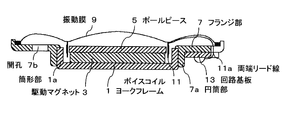
- FIG. 1 As a speaker apparatus worn on a user's ear, for example, there is a configuration as shown in FIG.
- the disk-shaped drive magnet 3 is fixed to the inner bottom portion of the cup-shaped magnetic yoke frame 1 and the disk-shaped pole piece 5 is coaxially fixed on the drive magnet 3.
- the cylindrical portion 1a of the frame 1 is fitted into the cylindrical portion 7a of the ring plate-like flange portion 7 to be integrated and fixed.
- the outer peripheral portion of the thin vibrating membrane 9 is fixed to the outer edge portion of the flange portion 7 so as to face the flange portion 7 and the pole piece 5 at a distance.
- a voice coil 11 in which a thin insulated wire is formed in a cylindrical shape is fixed to the central portion of the diaphragm 9 on the yoke frame side, and the voice coil 11 is annularly formed between the pole piece 5 and the cylindrical portion 1 a of the yoke frame 1.
- the voice coil 11 is inserted into the air gap, and the lead wires 11 a at both ends of the voice coil 11 are led out through the outer peripheral portion of the vibrating membrane 9 and connected to the circuit board 13 disposed on the lower surface of the flange portion 7.
- the outer peripheral region of the outer periphery of the voice coil 11 in the vibrating membrane 9 and the flange portion 7 form a sealed space.
- Reference numeral 7 b in FIG. 10 denotes a plurality of holes formed in the flange portion 7 and communicating with the outside. Conventionally, in order to adjust the sound quality characteristics of the speaker device, the following two configurations have generally been made.
- the first is a configuration in which the acoustic damping material is attached to the opening of the cover (not shown) that covers the back of the speaker, leaving the opening 7b as it is.
- the second is a configuration in which an acoustic damping material is attached to the opening 7b while the opening of the cover is opened.
- the speaker device as an actual product is configured as an intraconca type by housing the yoke frame 1 and the flange portion 7 in the main body case, and is surrounded by the user's tragus, antiparallel and concha
- the main body case is inserted and used in such a manner that the vibrating membrane 9 is brought close to the concha and the concha cavity.
- Patent Document 1 Japanese Patent Application Laid-Open Nos. 8-172691
- Patent Document 2 Japanese Patent Application Laid-Open 10-66181
- the two end lead wires 11a are drawn out from one position P1 near the root of the voice coil 11 in the outer peripheral direction of the diaphragm 9,
- a voice signal is applied to the lead wires 11a at both ends to displace and vibrate the voice coil 11, the following effects are likely to occur.
- the load applied to the vibrating membrane 9 by the both-ends lead wire 11a is concentrated at one position of the leading position P1, and the vibration displacement of the leading position P1 in the vibrating membrane 9 is suppressed.
- both end lead wires 11a are drawn toward the flange portion 7 so as to draw an arc from the lead-out position P1 and the both end lead wires 11a are fixed to the vibrating membrane 9 and the flange portion 7 with a flexible adhesive. It is known to. In this configuration as well, the whole of the fixed parts including the lead-out position P1 is subjected to vibrational load, and rolling movement is also likely to occur.
- the beat sound is a sum signal or a difference signal of the high frequency signal and the low frequency harmonic distortion.
- the low frequency signal sound is 50 Hz and the high frequency signal sound is 2000 Hz, ... 1850, 1900,
- addition and subtraction signals such as 1950, 2050, 2100, 2150 Hz and so on.
- the flange portion 7 is formed with a plurality of openings 7b, and the positional relationship between the lead portions of the lead wires 11a and the openings 7b is not particularly defined.
- the present invention has been made to solve such problems, and has a wide frequency band and excellent transient response characteristics in an intra-concha type speaker device having a lowest resonance frequency of 300 Hz or less as the device, in particular, a bass region. It is an object of the present invention to provide a speaker device capable of reproducing high quality sound.
- a first configuration according to the speaker device of the present invention is a yoke frame formed in a cup shape, and the open tip end side is extended toward the outer periphery and the outer diameter
- a magnetic yoke frame having an annular flange portion in the range of 12 mm to 20 mm, and a cylindrical drive magnet coaxially fixed to the bottom of the yoke frame with one end face in the yoke frame;
- a ring-shaped pole piece coaxially superimposed on the other end face of the drive magnet in the yoke frame, and a flange so as to face and close the pole piece and the flange portion at a distance
- a thin vibrating membrane fixed to the outer periphery of the part and a thin insulated wire are wound to form a cylinder, and the central area is surrounded on one surface of the vibrating membrane on the yoke frame side
- the outer peripheral region of the voice coil from the vicinity of the root to the outer periphery of the vibrating membrane faces the flange portion to form a sealed space with it, and the lead wires at both ends are derived from diagonal positions at the root of the voice coil, It is a first communication hole which is formed one pair each in the flange part on the orthogonal imaginary line orthogonal to the center of the imaginary line connecting the lead-out positions of the both end leads and communicates the sealed space to the outside
- a first communication hole for adjusting the acoustic impedance of the sealed space and a second communication hole for communicating the inside of the yoke frame to the outside through the respective center portions of the yoke frame, the drive magnet and the pole piece.
- one end face is coaxial with a cylindrical magnetic yoke frame and a fixed portion formed by bending from one end face side of the yoke frame to the outside.
- a drive magnet having a fixed ring plate shape, which is circumferentially opposed to the outer periphery of the cylindrical portion of the yoke frame, and the other end face side of the drive magnet on the outer periphery of the yoke frame
- An axially fixed ring-shaped pole piece having a tip extending to the outer periphery than the magnet, and a pole for facing and closing the yoke frame and the pole piece at a distance
- a thin diaphragm fixed to the tip of the piece and a thin insulated wire are wound to form a cylinder, and the center of the diaphragm on the yoke frame side is formed.
- the outer diameter of the fixed portion of the yoke frame is in the range of 12 mm to 20 mm, and the outer peripheral region of the vibrating film from near the base of the voice coil to the outer periphery mainly forms a sealed space between this and the pole piece
- the lead wires at both ends are derived from the diagonal position at the root of the voice coil, and each one of the flanges on the orthogonal imaginary line orthogonal to the center of the imaginary line connecting the lead positions of the lead wires
- a second communication hole, which has a second communication hole for adjusting the acoustic impedance of the sealed space, and the lowest resonance frequency is selected to be 300 Hz or less.
- the pair of first communication holes are each selected to have an inner diameter of 0.35 mm to 1.5 mm, and the second communication holes have an inner diameter of 0.8 mm to 2.5 mm. Configurations selected for are also possible.
- a configuration is also possible in which a pair of the first communication holes are closed with an acoustic resistance material.
- first and second configurations a configuration is also possible in which the lead wires at both ends are led out in opposite directions along the vibrating membrane and then led out via the second communication hole.
- both-ends lead wires are derived in mutually opposite directions along the vibrating film and are derived from the outer peripheral direction of the vibrating film.
- the lead wires at both ends are derived from the diagonal positions at the root of the voice coil, and are orthogonal to a virtual line connecting the lead positions of the lead wires.
- the inside of the yoke frame is made via the first communication holes for adjusting the acoustic impedance, one pair each being formed in the flange portion on the imaginary imaginary line, and the respective center portions of the yoke frame, the drive magnet and the pole piece.
- a second communication hole for adjusting the acoustic impedance that communicates with the outside.
- the lowest resonance frequency is selected to be 300 Hz or less
- a practical degree of sealing of the sealed space is secured, and the vibrating film is uniform near the lead position of the both lead wires from the voice coil. Vibration is secured.
- the rolling motion of the vibrating membrane is prevented, and the smooth piston motion motion of the vibrating membrane is ensured, and as a result, it is possible to obtain excellent transient response, low distortion, and a wide frequency band. In particular, high quality sound reproduction becomes possible in the low frequency range.
- the lead wires at both ends are derived from diagonal positions at the root of the voice coil, and orthogonal virtual lines orthogonal to imaginary lines connecting lead positions of the lead wires.
- the degree of practical sealing of the sealed space is secured, and the diaphragm uniform around the lead position of the both lead wires from the voice coil Vibration is secured, and it is possible to obtain the same effect as the internal magnet type configuration.
- the inner diameter of each of the pair of first communication holes is selected to be 0.35 mm to 1.5 mm, and the inner diameter of the second communication hole is 0.8 mm to 2.5 mm If selected, it is sure that the above-described effects can be obtained in speaker devices of various sizes.
- first and second configurations if a pair of the first communication holes is closed with an acoustic resistance material, it is easy to obtain a desired acoustic impedance without reducing the inner diameter of the first communication holes. easy.
- both-ends lead wires are derived in mutually opposite directions along the vibrating film and are derived from the outer peripheral direction of the vibrating film .
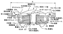
- FIG. 1 is an essential part longitudinal sectional view showing an embodiment of a first configuration according to the speaker device of the present invention.
- the yoke frame 15 is formed into a cup shape from a magnetic plate material, and a ring plate shape formed by bending the open end side (upper side in FIG. 1) of the cylindrical portion 15a outward.
- the flange portion 15b is integrally formed, and the outer peripheral portion 15c of the flange portion 15b is bent so as to slightly rise upward in the figure.
- the outer periphery of the flange portion 15b, that is, the outer diameter (S) of the yoke frame 15 is selected to be, for example, about 12 mm to 20 mm.
- a through hole 15e is formed in the center of the bottom 15d of the yoke frame 15, and a cylindrical (ring) drive magnet 17 is accommodated in the yoke frame 15 so that the hollow portion 17a is aligned with the through hole 15e.
- the drive magnet 17 is housed in the yoke frame 15 with one end face (lower side in FIG. 1) overlapping the bottom portion 15 d so as to surround the through hole 15 a.
- a ring-shaped pole piece formed on the other end face (upper side in FIG. 1) of the drive magnet 17 having an outer diameter equal to or slightly larger than the outer diameter of the drive magnet 17 and made of a magnetic material 19 is piled up.
- the pole piece 19 has a hollow portion 19 a aligned with the hollow portion 17 a of the drive magnet 17.
- a circuit board 21 having a through hole 21a is overlapped on the outside of the bottom portion 15d of the yoke frame 15 so that the through hole 21a is aligned with the through hole 15e.
- the yoke frame 15, the drive magnet 17, the pole piece 19 and the circuit board 21 have both ends of the tubular bolt 23 penetrated from the pole piece 19 or the circuit board 21 side to the hollow portions 17a, 19a and the through holes 15e, 21a. It is coaxially integrated by caulking.
- the hollow portion 23a of the hammer 23 has an inner diameter (S2) of about 0.8 mm to 2.5 mm.
- the yoke frame 15, the drive magnet 17, the pole piece 19, and the circuit board 21 may be coaxially integrated and fixed by an adhesive (not shown) or the like.
- the hollow portions 17a and 19a and the through holes 15e and 21a have the same inner diameter (S2) as the hollow portion 23a.
- the outer periphery of the pole piece 19 circumferentially faces the tip end of the cylindrical portion 15a of the yoke frame 15, that is, at the same level position as the bent portion from the cylindrical portion 15a to the flange portion 15b.
- a magnetic circuit is formed by the magnetic flux generated from the drive magnet 17 between the outer periphery of the pole piece 19 and the end of the cylindrical portion 15a of the yoke frame 15 opposed to the outer periphery of the pole piece 19 with a slight space therebetween.
- the vibrating film 25 is formed in a disk shape from a conventionally known thin and translucent insulating film material, and a central region formed by slightly expanding a relatively wide central portion in a dome shape. 25a and an outer peripheral area 25b concentrically and annularly surrounding the central area 25a.
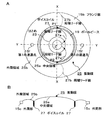
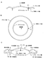
- FIG. 2A is shown in a state in which the pole piece 19, the flange portion 15 b and the voice coil 27 described later can be seen through the translucent vibrating membrane 25.
- the vibrating film 25 has a space for covering the flange portion 15b of the yoke frame 15 and the pole piece 19 as shown in FIG. 1, and covers the entire outer periphery of the outer peripheral region 25b as the outer peripheral portion 15c of the flange portion 15a. Is fixed by an adhesive or the like, and supported by the outer peripheral portion 15c.
- the voice coil 27 is formed by cylindrically winding a thin insulated wire covered with an insulating coating at an annular boundary between the central region 25a and the outer peripheral region 25b on one surface side (lower surface side in FIG. 1) of the vibrating film 25. One end face side is fixed so as to surround the central region 25a (see FIG. 2).
- the voice coil 27 slightly spaces the yoke frame 15 from the drive magnet 17 and the pole piece 19 with respect to the annular gap between the inner wall of the cylindrical portion 15 a of the yoke frame 15 and the outer periphery of the drive magnet 17 and the pole piece 19. , And are annularly opposed to the inner periphery of the yoke frame 15 and the outer periphery of the drive magnet 17 respectively.
- the two end leads 27a extending from the voice coil 27 are drawn inward from diagonal positions P1 and P2 at the root of the voice coil 27, as shown in FIG. 2A, and as shown in FIG. It is led to the outside through the hollow portion 23a of the above, that is, the hollow portions 19a and 17a of the pole piece 19 and the drive magnet 17, the bottom portion 15d of the yoke frame 15, and the through holes 15e and 21a of the circuit board 21 and connected to the circuit board 21. ing.
- the lead wires 27a at both ends are wired in the air with a margin not to be stressed even by the vibration of the vibrating film 25. That is, the lead wires 27a at both ends do not contact other than the lead points P1 and P2 and the bolt 23.
- the two end lead wires 27b are led out from the diagonal position at the base of the voice coil 27 as shown by the broken line in FIG. 2A, and the vibrating film 25 is formed at the outer peripheral portion 15c of the flange portion 15b.
- a configuration is also possible in which it is derived outside from the
- the outer peripheral area 25b of the vibrating membrane 25 is in the yoke frame 15, forms a sealed space E with the flange portion 15b, and faces the sealed space E.
- the sealed space E is a narrow annular gap between the voice coil 27 and the drive magnet 17 and the pole piece 19 from the narrow gap between the cylindrical portion 15 a of the yoke frame 15 and the voice coil 27, and the hollow portion of the bolt 23. It is communicated with the outside through 23a and sealed indirectly.
- the sealed space E has an air damper function to support the entire outer peripheral area 25b of the vibrating membrane 25 with uniform load.
- first communication holes 15f communicating with the outside from the sealed space E are formed at two diagonal positions.
- the inner diameter (S1) of the first communication hole 15f is selected to be, for example, 0.35 mm to 1.5 mm.
- each first communication hole 15f is a flange on an orthogonal imaginary line Y orthogonal to the imaginary line X at the center Z of the imaginary line X connecting the lead positions P1 and P2 of the lead wires 27a.
- a pair is formed one by one in the portion 15b. That is, in the flange portion 15b, the first communication holes 15f are formed in a pair at positions farthest from the lead-out positions P1 and P2.
- Each first communication hole 15 f is a member for adjusting the acoustic impedance of the sealed space E, and in the vicinity thereof, the acoustic impedance of the sealed space E is reduced, and particularly the low region without suppressing the vibration of the vibrating membrane 25.
- An audio signal is supplied from an electronic device (not shown) to the circuit board 21 superimposed on the bottom portion 15 d of the yoke frame 15 by a cable 29 described later.
- the voice coil 27 is displaced by the application of the voice signal to the voice coil 27 via the both-ends lead wire 27a, and the vibrating membrane 25 is driven to vibrate.
- the drive unit 31 for vibrating and driving the vibrating film 25 is formed by the yoke frame 15, the drive magnet 17, and the voice coil 27, and becomes a main part of a so-called internal magnet type speaker device. .
- the hollow portion 23a of the bolt 23 is a second communication hole which indirectly makes the sealed space E communicate with the outside similarly to the first communication hole 15f described above, and a member for adjusting the acoustic impedance of the sealed space E While having a function as, it has an action to lower the acoustic impedance to the vibration of the central region 25a of the vibrating film 25 and to facilitate the vibration.
- the hollow portion 23a (second communication hole) has an inner diameter (S2) selected to be, for example, 0.8 mm to 2.5 mm.
- the speaker apparatus mentioned above is comprised so that the minimum resonant frequency may be 300 Hz or less by adjusting the shape and dimension of the component which were mentioned above.
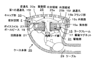
- the outer peripheral portion 15c of the flange portion 15b is fitted in the cap portion 33, and the cup-shaped case main body 35 is fitted in the cap portion 33 from below the flange portion 15b.
- the case main body 35 are housed and supported in the case main body 35 so as to be sandwiched between the cap portion 33 and the case main body 35.
- a plurality of sound through holes 33a for transmitting the driving sound due to the vibration of the vibrating membrane 9 to the outside are formed in a penetrating manner, and the cable 29 is inserted into the case main body 35 from the outside. It is connected to the.
- the cap portion 33 and the case main body 35 are both molded from a synthetic resin, and integrated by fitting them together to be commercialized as an earphone device.
- the drive unit 31 causes the diaphragm 25 to vibrate and the vibration sound is transmitted to the outside from the sound through hole 33a. It is propagated.
- the lead-out positions P1 and P2 of the lead wires 27a at both ends of the voice coil 27 are at two diagonal positions, and compared to the configuration in which they are one position. It is possible to disperse the load on 25 and to suppress the occurrence of rolling motion in the vibrating membrane 25.
- the acoustic impedance near the lead-out positions P1 and P2 becomes high, and a line connecting the lead-out positions P1 and P2 of the lead wires 27a to the vibrating membrane 25 It is also possible to suppress seesaw-like motion with a linear fulcrum (node).
- the acoustic impedance at this position is high, and the seesaw motion as described above is suppressed, but the resonance sharpness of the resonance frequency f 0 of the speaker device ( Q) drops, and sufficient low-pass reproduction can not be obtained.
- the resonance sharpness (Q) of the resonance frequency f 0 can be maintained at an appropriate value, and sufficient low frequency sound can be reproduced.
- the entire vibrating membrane 25 is displaced in a smooth piston mode, and a wide frequency band, an excellent transient response waveform, particularly high in a low band It is possible to obtain quality reproduced sound. Specifically, the sense of localization of a musical instrument or the like is improved, and the reproduced sound can be easily determined.
- the vibrating membrane 7 is likely to cause an operation called rolling motion due to the load of the lead wires 9a. Was being done. Therefore, in order to absorb the distortion during vibration of the vibrating film 7 to a certain extent, it is general to make the portion corresponding to the central region 7a into a spherical shape so as to bend and vibrate to some extent.
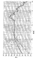
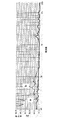
- FIG. 4 is a frequency characteristic diagram showing the speaker apparatus of the configuration according to the present invention of FIG. 1 and the conventional configuration of FIG. 10, and FIG. 5 shows the speaker device of the configuration according to the present invention of FIG. It is a distortion rate characteristic view.
- the sound pressure characteristics in a low sound range tend to deteriorate like the frequency characteristics shown by the broken line b in FIG.
- the harmonic distortion characteristic is bad, and particularly the deterioration of the bass region of around 100 Hz or less is remarkable.
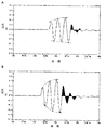
- the transient response waveform shown by the configuration of the speaker apparatus according to the present invention is as shown in FIG. 6A, and there is little disturbance of the output signal waveform when a 3 KHz tone burst signal is applied, and the transient response waveform is good. I understand.
- the frequency characteristics in a wide frequency band, particularly the mid-bass frequency band And, it has excellent transient response characteristics, and high-quality sound reproduction is possible especially in the low-pitch range.
- the first communication hole 15f formed in the flange portion 15b is It is preferable to set the inner diameter to 0.35 mm to 0.8 mm according to the target frequency characteristics and acoustic characteristics.
- the first communication hole 15f is formed in the range of 0.8 mm to 1.5 mm, and a damping member is attached to the aperture to make an acoustic A configuration for adjusting the impedance is also possible.
- the inner diameter (S2) of the second communication hole (hollow portion) 23a can be selected to be 0.8 mm to 2.5 mm in accordance with the easiness of manufacture and the desired frequency characteristics and acoustic characteristics.
- the outer diameter (S) of the yoke frame 15 can be selected in the range of 12 mm to 20 mm in accordance with the ease of manufacture and the desired frequency characteristics and acoustic characteristics.
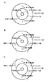
- the lead-out directions of the two end lead wires 27a are not limited to FIG. 2 described above, and for example, the configurations shown in FIGS. 7A to 7C are also possible. The same applies to the following embodiments.
- FIG. 7A shows a configuration in which both lead wires 27a are led out in mutually opposite directions along the film surface of the vibrating film 25 and then through the hollow portion 23a
- FIG. 7B is a film surface of the vibrating film 25.
- the structure shown in FIG. 6C is derived in the opposite direction from each other along the film surface of the vibrating film 25 and the vibrating film 25 is also derived in the same direction after being drawn out in the same direction. It is the structure derived
- the lead wires 27a at both ends are wired in the air with a margin not to be stressed even by the vibration of the vibrating film 25.
- FIG. 8 is a longitudinal sectional view of an essential part showing an embodiment of the second configuration according to the speaker device of the present invention.
- the yoke frame 37 is formed into a cylindrical shape from a magnetic plate material, and a ring plate-like fixing portion 37a formed by bending the open end on the lower side in the figure to the outside is integrated. Have to.
- a ring-shaped drive magnet 39 is coaxially fitted on the outer periphery of the yoke frame 37 at a distance from the outer periphery of the cylindrical portion 37b, and one end face (lower side in FIG. 8) is fixed to the fixing portion 37a. ing.
- a pole piece 41 formed in a ring plate shape from a magnetic body with an inner diameter approximately the same size as or slightly smaller than the inner diameter of the drive magnet 39 is superimposed. ing.
- the outer peripheral tip end 41a of the pole piece 41 is bent slightly upward (upper side in FIG. 8).
- the outer diameter (S) of the pole piece 41 (tip 41a) is selected to be, for example, 12 mm to 20 mm.
- the drive magnet 39 and the pole piece 41 have the same outer circumference, and the inner circumference of the pole piece 41 is substantially the same as that of the drive magnet 39 projecting inward.
- the pole piece 41 faces the other end of the yoke frame 37 at substantially the same level position.
- a circuit board 43 having a through hole 43a with an inner diameter (S2) of 0.8 mm to 2.5 mm is superimposed on the outer side of the fixing portion 37a of the yoke frame 37.
- the through hole 43a has the same function as that of the second communication hole (the second hollow portion 23a) described above.
- the fixing portion 37a of the yoke frame 37, the drive magnet 39, the pole piece 41, and the circuit board 43 are coaxially integrated by, for example, an adhesive and fixed to the fixing portion 37a of the yoke frame 37.
- a magnetic circuit is formed by the magnetic flux from the drive magnet 39 between the inner periphery of the pole piece 41 and the end of the yoke frame 37 opposed to the inner periphery of the pole piece 41 with a slight distance therefrom.
- the vibrating membrane 45 is formed in a disk shape from a conventionally known thin insulating film material, and has a central region 45a formed by slightly expanding a relatively wide central portion into a dome shape, and the central region And an outer peripheral region 45b concentrically and annularly surrounding 45a.
- the other configuration of the vibrating membrane 45 is the same as that of the vibrating membrane 25 of FIG.
- the vibrating membrane 45 has a space for the yoke frame 37 and the pole piece 41 to cover them, and the entire outer periphery of the outer peripheral area 45 b is fixed to the tip 41 a of the pole piece 41 with an adhesive or the like It is done.
- One end face side of the voice coil 47 wound and integrated into a shape is fixed so as to surround the central region 45a.
- the voice coil 47 is inserted into the annular gap between the outer wall of the yoke frame 37 and the inner periphery of the drive magnet 39 and the pole piece 41 at a slight distance from the yoke frame 37, the drive magnet 39 and the pole piece 41,
- the outer periphery of the yoke frame 37 and the inner periphery of the drive magnet 39 and the pole piece 41 are annularly opposed.
- the lead wires 47a at both ends of the voice coil 47 are derived from two diagonal positions as shown in FIG. 9 and penetrate the through holes 43a of the circuit board 43 through the hollow portion of the yoke frame 37, and the circuit board Connected to the 43.
- FIG. 9 is schematically illustrated.
- the sealed space E communicates with the outside from the narrow gap between the pole piece 41 or the drive magnet 39 and the voice coil 47 through the hollow portion of the yoke frame 37 and the through portion 43a of the circuit board 43 and is indirectly sealed. It has a function of supporting the entire outer peripheral area 45b of the voice coil 47 with uniform load.
- the first communication hole 41b is 1 on the orthogonal virtual line Y orthogonal to the center Z of the virtual line X connecting between the lead positions P1 and P2 of the lead wires 47a. A pair is formed penetrating one by one.
- the inner diameter (S1) of the first communication hole 41b is selected to be, for example, 0.35 mm to 1.5 mm, as in FIG.
- An audio signal is supplied from an electronic device (not shown) to the circuit board 43 overlapped with the fixing portion 37a of the yoke frame 37 by a cable (not shown).
- the voice coil 47 is displaced by the application of the voice signal to the voice coil 47 via the lead wires 47a at both ends, and the diaphragm 45 vibrates.
- the yoke frame 37, the drive magnet 39 and the voice coil 47 form a drive unit 49 for vibrating the diaphragm 45, which is a main part of a so-called external magnet type speaker device .
- the yoke frame 37 is fitted in the cap-like case main body 35 and supported in the case main body 35 as shown in FIG. 3 described above, and thus the illustration and description thereof will be omitted.
- the product production example and usage example of the earphone device are the same, and therefore, the description and illustration thereof will be omitted.
- the sealed space E in the second configuration of the present invention is formed between the pole piece 41 and the outer peripheral region 45 b of the vibrating membrane 45 and faces this, and functions to support the load of the outer peripheral region 45 b of the vibrating membrane 45 Is the same as the first configuration as long as it has
- the second configuration according to the present invention is the same as the first configuration in its operation and effects, and the frequency characteristics and the total harmonic distortion characteristics are as shown in FIG. 4 and FIG. It has a transient response characteristic, and high-quality sound reproduction is possible especially in the low-pitch range.
- the first communication hole is formed with an outer diameter (S) of the pole piece 41 (tip portion 41a) in the range of 12 mm to 20 mm according to the ease of manufacture and the intended characteristics.
- the inner diameter (S1) of 41b can be selected in the range of 0.35 mm to 1.5 mm
- the inner diameter (S2) of the second communication hole (through hole) 43a can be selected in the range of 0.8 mm to 2.5 mm. It is the same as the first configuration described above.
- the inner diameter of the first communication holes 15f and 41a is small and it is difficult to form a through hole, the inner diameter is made larger and air permeability is increased. It is the same as the first configuration that the sheet-like acoustic resistance material having the same is used to close them, to obtain an equivalent acoustic resistance and to change the acoustic impedance.
Landscapes
- Physics & Mathematics (AREA)
- Engineering & Computer Science (AREA)
- Acoustics & Sound (AREA)
- Signal Processing (AREA)
- Audible-Bandwidth Dynamoelectric Transducers Other Than Pickups (AREA)
Abstract
L'invention vise à permettre une reproduction sonore de haute qualité, en particulier à des basses fréquences audio, dans un dispositif haut-parleur. Selon la présente invention, un aimant d'excitation 17 est fixé à l'intérieur d'une carcasse 15 comprenant une partie de bride 15b, et une membrane 25 dirigée vers l'aimant d'excitation est fixée à la section d'extrémité distale 15c de la partie de bride 15b. Une bobine acoustique 27 est fixée à la membrane 25. Une ligne de câble à deux extrémités 27a de la bobine acoustique 27 est tirée à partir de positions diagonales. Un espace scellé E est formé par une région circonférentielle externe 25b de la membrane 25 et de la partie de bride 15c. Dans la partie de bride 15b, une paire de premiers trous de communication 15f faisant communiquer l'espace scellé E et l'extérieur sont formés sur une ligne imaginaire passant par le milieu entre les positions à partir desquelles la ligne de câble à deux extrémités 27a est tirée. Un second trou de communication est formé dans une partie centrale de la carcasse 15.
Priority Applications (1)
| Application Number | Priority Date | Filing Date | Title |
|---|---|---|---|
| PCT/JP2017/039865 WO2019087375A1 (fr) | 2017-11-06 | 2017-11-06 | Dispositif haut-parleur |
Applications Claiming Priority (1)
| Application Number | Priority Date | Filing Date | Title |
|---|---|---|---|
| PCT/JP2017/039865 WO2019087375A1 (fr) | 2017-11-06 | 2017-11-06 | Dispositif haut-parleur |
Publications (1)
| Publication Number | Publication Date |
|---|---|
| WO2019087375A1 true WO2019087375A1 (fr) | 2019-05-09 |
Family
ID=66332993
Family Applications (1)
| Application Number | Title | Priority Date | Filing Date |
|---|---|---|---|
| PCT/JP2017/039865 Ceased WO2019087375A1 (fr) | 2017-11-06 | 2017-11-06 | Dispositif haut-parleur |
Country Status (1)
| Country | Link |
|---|---|
| WO (1) | WO2019087375A1 (fr) |
Citations (5)
| Publication number | Priority date | Publication date | Assignee | Title |
|---|---|---|---|---|
| JPH0288395U (fr) * | 1988-12-23 | 1990-07-12 | ||
| JPH06178390A (ja) * | 1992-12-04 | 1994-06-24 | T W Denki Kk | スピーカ装置 |
| JP2003259484A (ja) * | 2002-03-01 | 2003-09-12 | Matsushita Electric Ind Co Ltd | スピーカ |
| JP2008005119A (ja) * | 2006-06-21 | 2008-01-10 | Pioneer Electronic Corp | スピーカ装置 |
| WO2015136656A1 (fr) * | 2014-03-13 | 2015-09-17 | 賢太 田中 | Dispositif de haut-parleur |
-
2017
- 2017-11-06 WO PCT/JP2017/039865 patent/WO2019087375A1/fr not_active Ceased
Patent Citations (5)
| Publication number | Priority date | Publication date | Assignee | Title |
|---|---|---|---|---|
| JPH0288395U (fr) * | 1988-12-23 | 1990-07-12 | ||
| JPH06178390A (ja) * | 1992-12-04 | 1994-06-24 | T W Denki Kk | スピーカ装置 |
| JP2003259484A (ja) * | 2002-03-01 | 2003-09-12 | Matsushita Electric Ind Co Ltd | スピーカ |
| JP2008005119A (ja) * | 2006-06-21 | 2008-01-10 | Pioneer Electronic Corp | スピーカ装置 |
| WO2015136656A1 (fr) * | 2014-03-13 | 2015-09-17 | 賢太 田中 | Dispositif de haut-parleur |
Similar Documents
| Publication | Publication Date | Title |
|---|---|---|
| CN104272765B (zh) | 耳机 | |
| JP3196707U (ja) | デュアル周波数コアキシャルイヤホン | |
| JP6363792B2 (ja) | 電気音響変換装置 | |
| JP6108649B2 (ja) | スピーカ装置 | |
| JP2014090239A (ja) | スピーカ装置 | |
| JP7094015B2 (ja) | カナルタイプイヤホン | |
| WO2022215558A1 (fr) | Convertisseur électro-acoustique et unité de convertisseur électro-acoustique | |
| JP2019041271A (ja) | フレーム及びこれを用いるスピーカーユニット並びにヘッドホン、イヤホン | |
| JP4888282B2 (ja) | スピーカ | |
| JP2020182041A (ja) | 電気音響変換器 | |
| JP2005204215A (ja) | 電気音響変換器 | |
| JPH10257589A (ja) | 振動板及びこの振動板を備えるマイクロホン装置 | |
| JP5125871B2 (ja) | コーンスピーカ | |
| JP6846602B2 (ja) | 電気音響変換器 | |
| JPWO2012144040A1 (ja) | イヤホン | |
| JP2012044352A (ja) | スピーカー | |
| JP6989751B2 (ja) | ダストキャップおよびこれを用いる動電型スピーカー | |
| JP7062306B2 (ja) | スピーカ装置 | |
| WO2018225180A1 (fr) | Transducteur électroacoustique | |
| KR102543007B1 (ko) | 평판형 트위터 진동판을 적용한 투웨이 리시버 | |
| JP4413119B2 (ja) | スピーカ | |
| WO2017104125A1 (fr) | Transducteur électro-acoustique | |
| JP2018067780A (ja) | 電気音響変換装置 | |
| KR20230063537A (ko) | 자기유도 금속 진동판을 구비하는 트위터 스피커 | |
| KR20230083480A (ko) | 비대칭 구조를 갖는 평판형 트위터 스피커 |
Legal Events
| Date | Code | Title | Description |
|---|---|---|---|
| 121 | Ep: the epo has been informed by wipo that ep was designated in this application |
Ref document number: 17930342 Country of ref document: EP Kind code of ref document: A1 |
|
| NENP | Non-entry into the national phase |
Ref country code: DE |
|
| 122 | Ep: pct application non-entry in european phase |
Ref document number: 17930342 Country of ref document: EP Kind code of ref document: A1 |
|
| NENP | Non-entry into the national phase |
Ref country code: JP |