WO2019087513A1 - Dispositif de traitement d'informations, procédé de traitement d'informations et programme - Google Patents
Dispositif de traitement d'informations, procédé de traitement d'informations et programme Download PDFInfo
- Publication number
- WO2019087513A1 WO2019087513A1 PCT/JP2018/029985 JP2018029985W WO2019087513A1 WO 2019087513 A1 WO2019087513 A1 WO 2019087513A1 JP 2018029985 W JP2018029985 W JP 2018029985W WO 2019087513 A1 WO2019087513 A1 WO 2019087513A1
- Authority
- WO
- WIPO (PCT)
- Prior art keywords
- virtual object
- display
- information processing
- real
- processing apparatus
- Prior art date
- Legal status (The legal status is an assumption and is not a legal conclusion. Google has not performed a legal analysis and makes no representation as to the accuracy of the status listed.)
- Ceased
Links
Images


Classifications
-
- G—PHYSICS
- G06—COMPUTING OR CALCULATING; COUNTING
- G06V—IMAGE OR VIDEO RECOGNITION OR UNDERSTANDING
- G06V40/00—Recognition of biometric, human-related or animal-related patterns in image or video data
- G06V40/10—Human or animal bodies, e.g. vehicle occupants or pedestrians; Body parts, e.g. hands
- G06V40/103—Static body considered as a whole, e.g. static pedestrian or occupant recognition
-
- G—PHYSICS
- G06—COMPUTING OR CALCULATING; COUNTING
- G06F—ELECTRIC DIGITAL DATA PROCESSING
- G06F3/00—Input arrangements for transferring data to be processed into a form capable of being handled by the computer; Output arrangements for transferring data from processing unit to output unit, e.g. interface arrangements
- G06F3/01—Input arrangements or combined input and output arrangements for interaction between user and computer
- G06F3/048—Interaction techniques based on graphical user interfaces [GUI]
- G06F3/0481—Interaction techniques based on graphical user interfaces [GUI] based on specific properties of the displayed interaction object or a metaphor-based environment, e.g. interaction with desktop elements like windows or icons, or assisted by a cursor's changing behaviour or appearance
-
- G—PHYSICS
- G06—COMPUTING OR CALCULATING; COUNTING
- G06F—ELECTRIC DIGITAL DATA PROCESSING
- G06F3/00—Input arrangements for transferring data to be processed into a form capable of being handled by the computer; Output arrangements for transferring data from processing unit to output unit, e.g. interface arrangements
- G06F3/01—Input arrangements or combined input and output arrangements for interaction between user and computer
- G06F3/048—Interaction techniques based on graphical user interfaces [GUI]
- G06F3/0484—Interaction techniques based on graphical user interfaces [GUI] for the control of specific functions or operations, e.g. selecting or manipulating an object, an image or a displayed text element, setting a parameter value or selecting a range
-
- G—PHYSICS
- G06—COMPUTING OR CALCULATING; COUNTING
- G06T—IMAGE DATA PROCESSING OR GENERATION, IN GENERAL
- G06T19/00—Manipulating three-dimensional [3D] models or images for computer graphics
- G06T19/006—Mixed reality
-
- G—PHYSICS
- G06—COMPUTING OR CALCULATING; COUNTING
- G06T—IMAGE DATA PROCESSING OR GENERATION, IN GENERAL
- G06T7/00—Image analysis
- G06T7/20—Analysis of motion
-
- G—PHYSICS
- G06—COMPUTING OR CALCULATING; COUNTING
- G06T—IMAGE DATA PROCESSING OR GENERATION, IN GENERAL
- G06T7/00—Image analysis
- G06T7/90—Determination of colour characteristics
-
- G—PHYSICS
- G06—COMPUTING OR CALCULATING; COUNTING
- G06V—IMAGE OR VIDEO RECOGNITION OR UNDERSTANDING
- G06V10/00—Arrangements for image or video recognition or understanding
- G06V10/40—Extraction of image or video features
- G06V10/60—Extraction of image or video features relating to illumination properties, e.g. using a reflectance or lighting model
-
- G—PHYSICS
- G06—COMPUTING OR CALCULATING; COUNTING
- G06V—IMAGE OR VIDEO RECOGNITION OR UNDERSTANDING
- G06V20/00—Scenes; Scene-specific elements
- G06V20/20—Scenes; Scene-specific elements in augmented reality scenes
Definitions
- the present disclosure relates to an information processing device, an information processing method, and a program.
- a technique related to an image processing apparatus including a recognition unit that recognizes a position or a posture of an object shown in an image, and a display control unit that changes display of a virtual object related to the object according to the stability of recognition by the recognition unit (See, for example, Patent Document 1). According to such a technique, it is possible to prevent the user from being confused by the disturbance of the display of the virtual object.
- display delay of the virtual object may occur apart from the disturbance of the display of the virtual object. Furthermore, apart from the display delay, there is also a concept as to how easily the display delay of the virtual object is perceived by the user. Hereinafter, the user's perception of display delay is also referred to as “display delay feeling”.
- the sense of display delay of the virtual object becomes stronger, the sense of discomfort for the delay of display of the virtual object may be increased.
- the visibility of the virtual object may be reduced as the display of the virtual object is largely changed. Then, the technique which can reduce the discomfort with respect to the display of a virtual object is desired, suppressing the fall of the visibility of a virtual object.
- a position acquisition unit that acquires a position of a virtual object in the real space determined based on a recognition result of the real space according to an image captured by an imaging device, a position of the virtual object,
- An information processing apparatus comprising: a display control unit configured to control display of at least a boundary of the virtual object based on features of the real object existing in the real space and separated from the position of the virtual object; .
- An information processing method including controlling display of at least a boundary of the virtual objects based on the position of the virtual object and the features of the real object present in the real space.
- a position acquisition unit that acquires a position of a virtual object determined based on a position of a virtual camera calculated based on a recognition result of a real space according to an image captured by an imaging device according to the present disclosure
- a display control unit configured to control display of at least a boundary of the virtual object based on the position of the virtual object and the feature of the real object existing in the real space.
- a technology capable of reducing a sense of discomfort with respect to display of a virtual object while suppressing a decrease in the visibility of the virtual object.
- the above-mentioned effects are not necessarily limited, and, along with or in place of the above-mentioned effects, any of the effects shown in the present specification, or other effects that can be grasped from the present specification May be played.
- a plurality of components having substantially the same or similar functional configurations may be distinguished by attaching different numerals after the same reference numerals. However, when it is not necessary to distinguish each of a plurality of components having substantially the same or similar functional configuration, only the same reference numeral is given. Also, similar components in different embodiments may be distinguished by attaching different alphabets after the same reference numerals. However, when it is not necessary to distinguish each of similar components in particular, only the same reference numeral is attached.
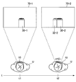
- FIG. 1 is a diagram for describing an overview of an embodiment of the present disclosure.
- a user U is present in the real space.
- the virtual object 30-1 is arranged in the field of view 70-1 of the user U.
- the virtual object 30-1 when the virtual object 30-1 is presented to the user U, it is for visual field analysis based on sensing data obtained by the visual field analysis imaging unit 111 (FIG. 5) (for example, a stereo camera etc.)
- the position and attitude (position of virtual camera) of the imaging unit 111 (FIG. 5) are recognized.
- the position of the virtual camera based on the position of the virtual camera, the position of the virtual object 30-1 in the field of view 70-1 is determined, and the virtual object 30-1 is displayed by the display based on the determined position of the virtual object 30-1. .
- the position of the virtual object is shifted between when the position of the virtual object is determined and when the virtual object is displayed by the display. That is, as shown in the field of view 70-2, the position of the virtual object 30-2 actually displayed by the display is the position 32-2 of the virtual object expected from the position of the virtual camera at the current time (time t2). There is a gap between them. Such a phenomenon is called display delay.
- the display delay feeling As an example, when there is no real object around the virtual object, it is assumed that the virtual object's sense of display delay is small because there is no real object around the virtual object that makes the display delay of the virtual object stand out Ru.
- FIG. 2 is a diagram for describing an overview of an embodiment of the present disclosure.
- a virtual object 30-14 is disposed in the field of view 70-14 of the user U.
- the user U moves his neck to the right from time t14 to time t15. Therefore, the field of view 70-14 is moved to the field of view 70-15.
- the position of the virtual object 30-15 actually displayed by the display is the position 32-15 of the virtual object expected from the position of the virtual camera at the present time (time t15).
- time t15 There is a gap between the Then, since the real object 40-2 exists near the virtual object 30-15, it is assumed that the sense of display delay is large.
- the real object when there is a real object whose luminance is not similar to the virtual object near the virtual object, the real object causes the display delay of the virtual object to be noticeable, so that the virtual object has a large sense of display delay. is assumed.
- the display delay of the virtual object is less noticeable when the virtual object has a movement as compared with the case where the virtual object has no movement, it is assumed that the display object of the virtual object has a smaller sense of display delay.
- FIG. 3 is a diagram for describing an overview of an embodiment of the present disclosure.
- a virtual object 30-16 is arranged in the field of view 70-16 of the user U.
- the user U moves his neck to the right from time t16 to time t17. Therefore, the field of view 70-16 is moved to the field of view 70-17.
- the position of the virtual object 30-17 actually displayed by the display is the position 32-13 of the virtual object expected from the position of the virtual camera at the present time (time t17).
- time t17 There is a gap between the Then, although the real object 40-2 exists near the virtual object 30-15, it is assumed that the sense of display delay is small because the definition of the virtual object 30-17 is lowered.
- a technique is proposed mainly capable of reducing the discomfort with respect to the display of the virtual object while suppressing the decrease in the visibility of the virtual object.
- the information processing apparatus 10 detects the distance between the user U and the real object as an example of the information on the real object.
- the information processing apparatus 10 includes a stereo camera, generates a depth map based on the left image and the right image captured by the stereo camera, and generates a depth map based on the depth map.
- the case of detecting the distance to a real object is mainly assumed.
- the distance between the user U and the real object may be detected in any way.
- the information processing apparatus 10 includes a distance sensor
- the distance sensor may detect the distance between the user U and the real object.
- the distance sensor may be a TOF (Time of Flight) sensor or the like.
- the type of the real object (for example, the shape, size, color, brightness, movement, etc. of the real object) is not particularly limited.
- the type of the virtual object 30 (for example, the shape, size, color, brightness, movement, etc. of the virtual object 30) is particularly limited I will not.
- the information processing apparatus 10 is configured by a goggle-type HMD (Head Mounted Display) mounted on the head of the user U is illustrated.
- the form of the HMD is not limited to the goggle type, and may be a glass type or the like.
- the information processing apparatus 10 is not limited to the HMD.
- the information processing apparatus 10 may be a smartphone, a tablet terminal, a mobile phone, or another mobile device.
- the information processing apparatus 10 has a transmissive display. At this time, the user U can visually recognize the virtual object 30 displayed by the display and can visually recognize the real object on the far side of the display. However, the information processing apparatus 10 may have a non-transmissive display. At this time, the user U can visually recognize the real object by the image captured by the virtual object 30 displayed by the display and the camera of the information processing apparatus 10 and displayed by the display.
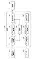
- FIG. 4 is a diagram showing an example of a functional configuration of the information processing apparatus 10 according to the embodiment of the present disclosure.
- the information processing apparatus 10 includes a visual field analysis imaging unit 111, a sensor unit 112, a control unit 120, a storage unit 130, and a display unit 150.
- the visual field analysis imaging unit 111 has a function of obtaining an image (visual field analysis image) by imaging the visual field of the user U.
- the visual field analysis imaging unit 111 includes a stereo camera, and obtains a left image and a right image captured by the stereo camera.
- the left image and the right image captured by the stereo camera are used for distance detection by the distance measuring unit 124 (FIG. 5).
- various distance sensors may be used instead of the stereo camera and the distance measuring unit 124.
- the visual field analysis imaging unit 111 may be integrated with the information processing apparatus 10 or may exist separately from the information processing apparatus 10.
- the sensor unit 112 includes a sensor, and has a function of detecting the movement of the user U's field of view.
- the sensor unit 112 may include an acceleration sensor, and may detect the movement of the field of view of the user U by the acceleration detected by the acceleration sensor.
- the sensor unit 112 may be configured to include a gyro sensor, and may detect the movement of the field of view of the user U by the angular velocity detected by the gyro sensor.
- the sensor unit 112 may not be provided.
- the storage unit 130 is configured to include a memory, and is a recording medium that stores a program executed by the control unit 120 or stores data necessary for the execution of the program. In addition, the storage unit 130 temporarily stores data for the calculation by the control unit 120.
- the storage unit 130 is configured of a magnetic storage unit device, a semiconductor storage device, an optical storage device, a magneto-optical storage device, or the like.
- the display unit 150 has a function of displaying various screens.
- the type of the display unit 150 is not limited.
- the display unit 150 may be a display (display device) capable of performing display visible to the user. More specifically, the display unit 150 may be a liquid crystal display or an organic EL (Electro-Luminescence) display.
- the control unit 120 executes control of each unit of the information processing apparatus 10.
- FIG. 5 is a diagram showing a detailed configuration example of the control unit 120.
- the control unit 120 includes a real space information acquisition unit 121, a real object detection unit 122, a distance measurement unit 124, a self position estimation unit 125, an application execution unit 126, a position acquisition unit 127, and a display control unit. 128 is provided. The details of each of these functional blocks will be described later.
- the control unit 120 may be configured of, for example, one or more CPUs (central processing units). When the control unit 120 is configured by a processing unit such as a CPU, the processing unit may be configured by an electronic circuit.
- the real space information acquisition unit 121 acquires information of a real object (hereinafter, also referred to as an “object”) disposed in the real space. More specifically, the real space information acquisition unit 121 acquires information of a real object by acquiring a left image and a right image in which the real object appears from the field-of-view analysis imaging unit 111.
- the distance measuring unit 124 generates a depth map based on the left image and the right image captured by the visual field analysis imaging unit 111, and outputs the generated depth map to the display control unit 128.
- the real object detection unit 122 determines whether a predetermined real object (for example, a plane or the like) is present in the field of view based on the left image and the right image captured by the field of view analysis imaging unit 111. When a predetermined real object exists in the field of view, the real object detection unit 122 detects a feature of the predetermined real object in the field of view (for example, the position of a plane in the real space), and the application execution unit 126 and the display control unit 128 Output to The real object detection unit 122 may detect the feature of a predetermined real object based on the depth map generated by the distance measurement unit 124.
- a predetermined real object for example, a plane or the like
- the self position estimation unit 125 estimates the position and orientation (the position of the virtual camera) in the real space of the visual field analysis imaging unit 111 as the self position based on the recognition result of the real space.
- the self position estimation unit 125 recognizes the real space based on a plurality of images continuously captured temporally by the visual field analysis imaging unit 111.
- the self position estimation unit 125 further takes into consideration sensing data (for example, an acceleration detected by an acceleration sensor, an angular velocity detected by a gyro sensor, etc.) obtained by the sensor unit 112 in order to improve recognition accuracy.
- the real space may be recognized.
- the application execution unit 126 determines a virtual object to be placed in the virtual space, and determines the position of the virtual object in the virtual space. At this time, the application execution unit 126 may determine the position of the virtual object based on the features of the real object detected by the real object detection unit 122. As an example, when the real object detection unit 122 detects the position of the plane, the application execution unit 126 determines the position of the plane detected by the real object detection unit 122 as the position at which the virtual object is arranged. May be
- the application execution unit 126 is for analyzing the position of the virtual object in the visual field and the visual field analysis based on the position of the virtual object in the virtual space and the position and orientation (the position of the virtual camera) in the real space of the imaging unit for visual field analysis 111.
- the distance between the imaging unit 111 and the virtual object is detected.
- the type of application is not particularly limited. As one example, the application may be a game application.
- the position acquisition unit 127 acquires the position of the virtual object acquired by the application execution unit 123.
- the position acquisition unit 127 acquires the position of the virtual object acquired by the application execution unit 123 in the virtual space. Further, the position acquisition unit 127 acquires the position in the field of view of the virtual object acquired by the application execution unit 123.
- the display control unit 128 acquires the features of the real object detected by the real object detection unit 122. Further, the display control unit 128 acquires the depth map generated by the distance measuring unit 124. Further, the display control unit 128 acquires the position of the virtual object acquired by the position acquisition unit 127.
- the display control unit 128 determines the position of the virtual object acquired by the position acquisition unit 127 and the feature of the real object present in the real space detected by the real object detection unit 122 and separated from the position of the virtual object. Based on the display of at least the boundaries of the virtual object. According to this configuration, it is possible to reduce the sense of discomfort with respect to the display of the virtual object while suppressing the decrease in the visibility of the virtual object. For example, when the virtual object and the real object have the first positional relationship, the display control unit 128 displays at least the boundary of the virtual object at a second position where the virtual object and the real object are different from the first positional relationship. Different from when it is in a relationship.
- the display control unit 128 The display of at least the boundaries of the object may be changed.
- the display control unit 128 calculates the predicted strength of the display delay feeling of the virtual object based on the features of the real object. Then, the display control unit 128 controls the display of at least the boundary of the virtual object based on the position of the virtual object and the predicted strength of the display delay. More specifically, the display control unit 128 may control at least one of the position, the shape, the motion, the color, the luminance, and the definition of the boundary of the virtual object.
- the characteristics of the real object are not particularly limited.
- the features of the real object may include at least one of the shape and motion of the real object.
- the display control unit 128 may increase the prediction strength of the sense of display delay as the proportion of the straight portion of the edge of the real object increases.
- the display control unit 128 may increase the prediction strength of the sense of display delay as the movement of the real object is larger.
- the display control unit 128 may calculate the predicted strength of the display delay based on the characteristics of the real object, or may calculate the predicted strength of the display delay based on the characteristics of the virtual object, or the real object The predicted strength of the display delay may be calculated based on both the feature of and the feature of the virtual object.
- the characteristics of the virtual object are not particularly limited.
- the features of the virtual object may include at least one of the shape and motion of the virtual object.
- the display control unit 128 may increase the prediction strength of the sense of display delay as the proportion of the straight portion of the edge of the virtual object increases.
- the display control unit 128 may increase the prediction strength of the sense of display delay as the movement of the virtual object is larger.
- the predicted strength of the display delay may be determined for each virtual object. Further, the predicted strength of the display delay feeling may be determined in advance for each feature of the virtual object. In the following, a case will be specifically described in which the predicted strength of display delay feeling of the virtual object is determined in advance for each of the virtual object and the feature of the virtual object.
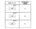
- 6 to 8 are diagrams showing examples of predicted strength of display delay feeling for each feature of the virtual object and the virtual object.
- a virtual object whose predicted intensity of display delay feeling corresponding to a virtual object 30-31 having a high proportion of straight portions of edges is indicated as “1.0” and the proportion of straight portions of edges is intermediate
- the predicted strength of display delay feeling corresponding to 30-32 is shown as "0.9”
- the predicted strength of display delay feeling corresponding to virtual object 30-33 with a low proportion of straight portions of edges is "0.7” It is shown as.
- the predicted strength of display delay feeling corresponding to the virtual object 30-34 without motion is shown as "0.4", corresponding to the virtual object 30-35 moving the eyes so that the user looks at the user.
- the predicted strength of the display delay feeling is shown as "0.35", and the predicted strength of the display delay feeling corresponding to the virtual object 30-36 with high motion is shown as "0.25".
- the virtual objects 30-35 for moving the eyes so that the user looks at them will be described later with reference to FIG.
- the predicted strength of the display delay feeling corresponding to the virtual object 30-37 moving with a small tail up and down is shown as “0.15”, and the virtual object moves with a large swing left and right
- the predicted strength of the display delay feeling corresponding to 30-38 is shown as "0.1".
- the predicted strength of display delay may be determined. Then, the display control unit 128 may change the display of at least the boundary of the virtual objects when the predicted strength of the display delay feeling exceeds the threshold. More specifically, when the display control unit 128 changes the position, shape, motion, color, brightness, and / or sharpness of the boundary of the virtual object when the predicted strength of the display delay feeling exceeds the threshold, Good.
- the predicted strength of the display delay feeling of the virtual object may be determined in advance for each of the virtual object and the feature of the virtual object in the application. Then, the virtual object after the change when the predicted strength of the display delay feeling exceeds the threshold may be determined in advance as an avoidance pattern in the application. The virtual object after the change may be determined as one, or the virtual object may be changed such that the reduction width of the prediction strength of display delay is larger as the prediction strength of the display delay is larger. The following describes an example of changing the display of a virtual object.
- FIG. 9 is a diagram showing an example of changing the color of a virtual object.
- the virtual object 30-3 is disposed in the field of view 70-3 of the user U.
- the user U moves his neck to the right, so at time t4, the field of view 70-3 of the user U is moved to the field of view 70-4.
- the display control unit 128 may thin the color of the virtual object 30-3 when the predicted strength of the display delay feeling exceeds the threshold. This is considered to reduce the feeling of display delay of the virtual object 30-4. For example, when the predicted strength of display delay feeling exceeds the threshold, the display control unit 128 sets the color of the virtual object 30-3 to the color of the real object 40-1 whose distance to the virtual object 30-3 is smaller than a predetermined distance. Should be close (virtual object 30-4). This is considered to reduce the feeling of display delay of the virtual object 30-4.
- the predicted strength of display delay may be calculated in any manner.
- the display control unit 128 determines the real object As the similarity between the color 40-1 and the color of the virtual object 30-3 is smaller, the predicted strength of the display delay may be calculated larger.
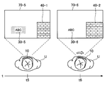
- FIG. 10 is a diagram showing an example of changing the luminance of the virtual object.
- the virtual object 30-5 is arranged in the field of view 70-5 of the user U.
- the user U moves his neck to the right, so at time t6, the visual field 70-5 of the user U moves to the visual field 70-6.
- the display control unit 128 may lower the luminance of the virtual object 30-5 if the predicted strength of the display delay feeling exceeds the threshold. This is considered to reduce the feeling of display delay of the virtual object 30-6. For example, when the predicted strength of display delay feeling exceeds the threshold, the display control unit 128 sets the brightness of the virtual object 30-5 to the brightness of the real object 40-1 whose distance to the virtual object 30-5 is smaller than a predetermined distance. Close to the virtual object 30-6).
- the predicted strength of display delay may be calculated in any manner.
- the display control unit 128 determines the real object As the difference between the brightness of 40-1 and the brightness of the virtual object 30-5 is larger, the predicted strength of the display delay may be calculated larger.
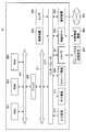
- FIG. 11 is a diagram illustrating an example of the relationship between the brightness of a real object, the brightness of a virtual object, and the predicted strength of display delay.
- the predicted strength of the sense of display delay corresponding to the luminance of the real object 40-3 and the luminance of each of the virtual objects 30-39 to 30-42 is shown.
- the predicted strength of the display delay feeling of the virtual object may be larger.
- the display control unit 128 may add motion to the virtual object or intensify the motion of the virtual object when the prediction strength of the display delay feeling exceeds the threshold.
- the display control unit 128 may change the movement of the virtual object from a no-motion state to a state in which the eyes are moved so that the user looks at the line when the predicted strength of display delay feeling exceeds the threshold. This is considered to reduce the display delay feeling of the virtual object.
- FIG. 12 is a diagram showing an example of a virtual object that moves the eyes so that the user looks at it.
- the visual field moves from the visual field 70-7 to the visual field 70-9.
- the virtual object 30-7 may move its eyes so that the user looks at it (virtual objects 30-8 and 30-9).
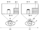
- FIG. 13 is a diagram showing an example of changing the luminance of the virtual object.
- virtual object 30-10 is arranged in the field of view 70-10 of user U.
- the user U moves his neck to the right, so at time t11, the field of view 70-10 of the user U is moved to the field of view 70-11.
- the display control unit 128 may lower the visibility (for example, the sharpness) of the boundary of the virtual object 30-10 when the predicted strength of the display delay feeling exceeds the threshold (for example, blur in the virtual object 30-10). (Virtual object 30-11). This is considered to reduce the feeling of display delay of the virtual object 30-10.
- the display control unit 128 may move the position of the virtual object away from the real object when the prediction strength of the display delay feeling exceeds the threshold. This is considered to reduce the display delay feeling of the virtual object. For example, the display control unit 128 may move the position of the virtual object away from the real object whose distance to the virtual object is smaller than a predetermined distance when the predicted strength of the display delay feeling exceeds the threshold.
- the display control unit 128 may change the shape of the virtual object when the predicted strength of the display delay feeling exceeds the threshold. This is considered to reduce the display delay feeling of the virtual object.
- the display control unit 128 may change the shape of the virtual object so that the proportion of the straight portion of the edge is lower when the predicted strength of the display delay feeling exceeds the threshold.
- the position of a straight line that constitutes a real object may be taken into consideration in calculating the prediction strength of the sense of display delay. That is, when the feature of the real object includes the position of a straight line that configures the real object, and the feature of the virtual object includes the position of the virtual object, the display control unit 128 determines the position of the virtual object and the straight line that configures the real object. As the distance to the position of is closer, the predicted strength of display delay may be calculated larger. Such an example will be described in detail with reference to FIG.
- FIG. 14 is a diagram for explaining an example of calculation of the predicted strength of the feeling of display delay based on the position of the straight line configuring the real object.
- the field of view 70-21 of the user U is shown.
- the virtual object 30-21 and the virtual object 30-22 are arranged in the field of view 70-21 of the user U.
- the display control unit 128 calculates the predicted strength of the sense of display delay more.
- the display control unit 128 may calculate the predicted strength of the display delay feeling corresponding to each of the perpendicular lines E11 to E14 as “0.2”, “0.18”, “0.15”, “0.05”.
- the display control unit 128 predicts the standard display delay feeling of the virtual object 30-21 “1.0”, assuming that the predicted strength of the standard display feeling of the virtual object 30-21 is “1.0”. Display the virtual object 30-21 by adding the predicted strengths “0.2”, “0.18”, “0.15” and “0.05” of the sense of display delay to the vertical lines E11 to E14 respectively. The predicted strength of the sense of delay may be calculated as “1.58”.
- the display control unit 128 may calculate the predicted strength of display delay feeling corresponding to each of the perpendiculars E21 to E23 as “0.03”, “0.018”, and “0.01”.
- the display control unit 128 predicts the standard display delay feeling of the virtual object 30-21 “1.0”, assuming that the predicted strength of the standard display feeling of the virtual object 30-21 is “1.0”. By adding the predicted strength “0.03” “0.018” “0.01” of the sense of display delay corresponding to each of the perpendiculars E21 to E23 to the estimated strength of the sense of display delay of the virtual object 30-22. May be calculated as "1.058".
- the predicted strength of display delay may be calculated based on the direction of the straight line forming the real object instead of the position of the straight line forming the real object. At this time, as the straight line forming the real object and the straight line forming the virtual object are closer to parallel, the predicted strength of the display delay may be calculated larger.
- the display control unit 128 configures the virtual object.
- the standard display delay feeling of the virtual object May be added to the predicted strength of
- the inner product of the direction vector of the straight line forming the virtual object and the direction vector of the straight line forming the real object May be used.
- the display control unit 128 controls the display of the virtual object based on at least one of the feature of the real object and the virtual object.
- the movement of the virtual camera may also change the feeling of display delay. Therefore, the display control unit 128 substitutes at least one of the features of the real object and the virtual object, or the display control unit 128 adds the feature to the real object and / or the virtual object, The display of at least the boundary of the virtual object may be controlled based on the movement of the camera.
- the display control unit 128 may change the display of at least the boundary of the virtual object when the motion of the virtual camera exceeds a predetermined motion. For example, when the movement of the virtual camera exceeds a predetermined movement, the display control unit 128 may increase the prediction strength of the display delay feeling of the virtual object. For example, the display control unit 128 may calculate the prediction strength of the display delay feeling of the virtual object to be larger as the movement of the virtual camera becomes larger. The display control of the virtual object based on the predicted strength of the display delay may be performed in the same manner as described above.
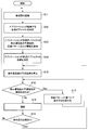
- FIG. 15 is a flowchart showing an operation example of the information processing apparatus 10 according to the present embodiment.
- the operation example illustrated in FIG. 15 merely illustrates an example of the operation of the information processing apparatus 10 according to the present embodiment. Therefore, the operation of the information processing apparatus 10 according to the present embodiment is not limited to the operation example shown in FIG.
- the self-position estimation unit 125 recognizes the real space based on a plurality of images continuously captured temporally by the visual field analysis imaging unit 111 (S11).
- the self position estimation unit 125 estimates the position and orientation (the position of the virtual camera) in the real space of the visual field analysis imaging unit 111 as the self position based on the recognition result of the real space.
- the application execution unit 126 determines a virtual object to be arranged in the virtual space (S12), and notifies the display control unit 128 of a combination of predicted intensity of display delay feeling of the virtual object, an avoidance pattern, and a threshold (S13).
- the application execution unit 126 determines the position of the virtual object in the virtual space (S14).
- the display control unit 128 calculates the predicted strength of the feeling of display delay based on at least one of the feature of the virtual object and the feature of the real object (S15).
- the display control unit 128 changes the display method of the virtual object based on the avoidance pattern (S17) when the predicted strength of the sense of display delay exceeds the threshold ("Yes" in S16), and shifts the operation to S16.
- the display method of the virtual object may be sequentially changed based on the avoidance pattern corresponding to each feature of the virtual object until the predicted strength of the display delay does not exceed the threshold.
- the display control unit 128 draws the virtual object (S18), and the characteristics of the virtual object and the characteristics of the real object. If it is necessary to make a redetermination ("Yes” in S19) because at least one of them is changed (S19), the operation is shifted to S15, but if the redetermination is not necessary (S19) The operation may be shifted to S11).
- FIG. 16 is a block diagram showing an example of the hardware configuration of the information processing apparatus 10 according to the embodiment of the present disclosure.
- the information processing apparatus 10 includes a central processing unit (CPU) 901, a read only memory (ROM) 903, and a random access memory (RAM) 905.
- the information processing apparatus 10 may also include a host bus 907, a bridge 909, an external bus 911, an interface 913, an input device 915, an output device 917, a storage device 919, a drive 921, a connection port 923, and a communication device 925.
- the information processing device 10 may include an imaging device 933 and a sensor 935 as necessary.
- the information processing apparatus 10 may have a processing circuit called a digital signal processor (DSP) or an application specific integrated circuit (ASIC) instead of or in addition to the CPU 901.
- DSP digital signal processor
- ASIC application specific integrated circuit
- the CPU 901 functions as an arithmetic processing unit and a control unit, and controls the entire operation or a part of the information processing apparatus 10 according to various programs recorded in the ROM 903, the RAM 905, the storage unit 919, or the removable recording medium 927.
- the ROM 903 stores programs used by the CPU 901, calculation parameters, and the like.
- the RAM 905 temporarily stores programs used in the execution of the CPU 901, parameters that appropriately change in the execution, and the like.
- the CPU 901, the ROM 903 and the RAM 905 are mutually connected by a host bus 907 configured by an internal bus such as a CPU bus. Furthermore, the host bus 907 is connected to an external bus 911 such as a peripheral component interconnect / interface (PCI) bus via the bridge 909.
- PCI peripheral component interconnect / interface
- the input device 915 is, for example, a device operated by the user, such as a mouse, a keyboard, a touch panel, a button, a switch, and a lever.
- the input device 915 may include a microphone that detects the user's voice.
- the input device 915 may be, for example, a remote control device using infrared rays or other radio waves, or may be an external connection device 929 such as a mobile phone corresponding to the operation of the information processing apparatus 10.
- the input device 915 includes an input control circuit that generates an input signal based on information input by the user and outputs the generated signal to the CPU 901.
- the user operates the input device 915 to input various data to the information processing apparatus 10 and instruct processing operations.
- an imaging device 933 described later can also function as an input device by imaging the movement of the user's hand, the finger of the user, and the like. At this time, the pointing position may be determined according to the movement of the hand or the direction of the finger.
- the output device 917 is configured of a device capable of visually or aurally notifying the user of the acquired information.
- the output device 917 is, for example, an LCD (Liquid Crystal Display), a PDP (Plasma Display Panel), an organic EL (Electro-Luminescence) display, a display such as a projector, a display of a hologram, an audio output such as a speaker and a headphone, And a printer device.
- the output device 917 outputs the result obtained by the processing of the information processing device 10 as a video such as text or an image, or outputs it as an audio such as audio or sound.
- the output device 917 may include a light or the like to brighten the surroundings.
- the storage device 919 is a device for data storage configured as an example of a storage unit of the information processing device 10.
- the storage device 919 is configured of, for example, a magnetic storage unit device such as a hard disk drive (HDD), a semiconductor storage device, an optical storage device, or a magneto-optical storage device.
- the storage device 919 stores programs executed by the CPU 901, various data, various data acquired from the outside, and the like.
- the drive 921 is a reader / writer for a removable recording medium 927 such as a magnetic disk, an optical disk, a magneto-optical disk, or a semiconductor memory, and is built in or externally attached to the information processing apparatus 10.
- the drive 921 reads out the information recorded in the mounted removable recording medium 927 and outputs it to the RAM 905.
- the drive 921 also writes a record on the attached removable recording medium 927.
- connection port 923 is a port for directly connecting a device to the information processing apparatus 10.
- the connection port 923 may be, for example, a Universal Serial Bus (USB) port, an IEEE 1394 port, a Small Computer System Interface (SCSI) port, or the like.
- the connection port 923 may be an RS-232C port, an optical audio terminal, a high-definition multimedia interface (HDMI (registered trademark)) port, or the like.
- HDMI registered trademark
- the communication device 925 is, for example, a communication interface configured of a communication device or the like for connecting to the communication network 931.
- the communication device 925 may be, for example, a communication card for a wired or wireless Local Area Network (LAN), Bluetooth (registered trademark), or WUSB (Wireless USB).
- the communication device 925 may be a router for optical communication, a router for Asymmetric Digital Subscriber Line (ADSL), or a modem for various types of communication.
- the communication device 925 transmits and receives signals and the like to and from the Internet or another communication device using a predetermined protocol such as TCP / IP.
- a communication network 931 connected to the communication device 925 is a network connected by wire or wireless, and is, for example, the Internet, a home LAN, infrared communication, radio wave communication, satellite communication, or the like.
- the imaging device 933 uses various members such as an imaging device such as a charge coupled device (CCD) or a complementary metal oxide semiconductor (CMOS), and a lens for controlling the formation of an object image on the imaging device. It is an apparatus which images real space and generates a captured image.
- the imaging device 933 may capture a still image, or may capture a moving image.
- the sensor 935 is, for example, various sensors such as a distance measuring sensor, an acceleration sensor, a gyro sensor, a geomagnetic sensor, an optical sensor, and a sound sensor.
- the sensor 935 acquires information on the environment of the information processing apparatus 10, such as information on the state of the information processing apparatus 10 itself, such as the attitude of the housing of the information processing apparatus 10, and brightness and noise around the information processing apparatus 10, for example. Do.
- the sensor 935 may also include a GPS sensor that receives a Global Positioning System (GPS) signal and measures the latitude, longitude and altitude of the device.
- GPS Global Positioning System
- the position of the virtual object determined based on the position of the virtual camera calculated based on the recognition result of the real space according to the image captured by the imaging device Information that includes: a position acquisition unit 127 that acquires the information; and a display control unit 128 that controls display of at least the boundary of the virtual object based on the position of the virtual object and the feature of the object present in the real space.
- a processing device 10 is provided.
- the position of each configuration is not particularly limited.
- a part of processing of each unit in the information processing apparatus 10 may be performed by a server device (not shown).
- a part or all of the blocks included in the control unit 120 in the information processing apparatus 10 may be present in a server apparatus (not shown) or the like.
- a server device not shown
- a position acquisition unit that acquires the position of a virtual object in the real space determined based on a recognition result of the real space according to an image captured by an imaging device;
- a display control unit configured to control display of at least a boundary of the virtual object based on the position of the virtual object and the features of the real object existing in the real space and separated from the position of the virtual object;
- An information processing apparatus comprising: (2) When the virtual object and the real object are in the first positional relationship, the display control unit is configured to display at least the boundary of the virtual object, and the virtual object and the real object are different from the first positional relationship. Different from the case of the second positional relationship, The information processing apparatus according to (1).
- the display control unit changes the positional relationship between the virtual object and the real object from the first positional relationship to the second positional relationship according to the movement of the field of view of the user who presents the virtual object , Changing the display of at least the boundaries of the virtual object, The information processing apparatus according to (2).
- the display control unit calculates the predicted strength of the display delay feeling of the virtual object based on the characteristics of the real object, and the virtual object based on the position of the virtual object and the predicted strength of the display delay feeling Control the display of at least the boundaries of The information processing apparatus according to (1).
- the display control unit moves the position of the virtual object away from the real object when the predicted strength of the display delay feeling exceeds a threshold.
- the information processing apparatus according to (4).
- the display control unit changes the shape of the virtual object when the predicted strength of the display delay feeling exceeds a threshold.
- the information processing apparatus according to (4). The display control unit imparts a motion to the virtual object or strengthens the motion of the virtual object when the prediction strength of the display delay feeling exceeds a threshold.
- the information processing apparatus according to (4). The display control unit brings at least one of the color or the luminance of the virtual object closer to at least one of the color or the luminance of the real object when the predicted strength of the display delay feeling exceeds a threshold.
- the information processing apparatus according to (4). (9) The display control unit reduces the visibility of the boundary of the virtual object when the predicted strength of the display delay feeling exceeds a threshold.
- the features of the real object include at least one of the shape and the motion of the real object, The information processing apparatus according to (1).
- the display control unit calculates the predicted strength of the display delay feeling based on the features of the real object and the features of the virtual object.
- the features of the real object include the positions of the straight lines that make up the real object,
- the features of the virtual object include the location of the virtual object
- the display control unit calculates the predicted strength of the display delay feeling to be larger as the distance between the position of the virtual object and the position of a straight line configuring the real object is shorter.
- the features of the real object include the direction of the straight lines that make up the real object
- the features of the virtual object include the direction of the straight lines that make up the virtual object
- the display control unit calculates the predicted strength of the sense of display delay more as the angle between the direction of the straight line forming the virtual object and the direction of the straight line forming the real object is smaller.
- the features of the virtual object include at least one of the shape and the motion of the virtual object.
- the features of the real object include the color of the real object
- the features of the virtual object include the color of the virtual object
- the display control unit calculates, as the similarity between the color of the real object and the color of the virtual object is smaller, the prediction strength of the display delay feeling larger.
- the features of the real object include the brightness of the real object
- the features of the virtual object include the intensity of the virtual object
- the display control unit calculates the predicted strength of the display delay feeling to be larger as the difference between the brightness of the real object and the brightness of the virtual object is larger.
- the display control unit controls display of at least a boundary of the virtual objects based on the movement of the virtual camera calculated based on the recognition result of the real space.
- the information processing apparatus changes display of at least a boundary of the virtual object when the motion of the virtual camera exceeds a predetermined motion.
- the information processing apparatus according to (17). (19) Acquiring a position of a virtual object determined based on a position of a virtual camera calculated based on a recognition result of real space according to an image captured by an imaging device; Controlling display of at least a boundary of the virtual object based on the position of the virtual object and the feature of the real object existing in the real space;
- Information processing methods including: (20) Computer, A position acquisition unit that acquires a position of a virtual object determined based on a position of a virtual camera calculated based on a recognition result of real space according to an image captured by an imaging device; A display control unit configured to control display of at least a boundary of the virtual object based on the position of the virtual object and the feature of the real object existing in the real space; Program for functioning as an information processing apparatus provided with
Landscapes
- Engineering & Computer Science (AREA)
- Theoretical Computer Science (AREA)
- Physics & Mathematics (AREA)
- General Physics & Mathematics (AREA)
- Multimedia (AREA)
- General Engineering & Computer Science (AREA)
- Human Computer Interaction (AREA)
- Software Systems (AREA)
- Computer Vision & Pattern Recognition (AREA)
- Computer Graphics (AREA)
- Computer Hardware Design (AREA)
- Processing Or Creating Images (AREA)
- User Interface Of Digital Computer (AREA)
Abstract
Le problème abordé par l'invention est d'obtenir une caractéristique qui permet de réduire une sensation d'inconfort à propos de l'affichage d'un objet virtuel tout en supprimant une réduction de la visibilité de l'objet virtuel. La solution de l'invention concerne un dispositif de traitement d'informations comprenant : une unité d'acquisition de position permettant d'acquérir la position d'un objet virtuel dans un espace réel qui correspond à une image capturée par un dispositif d'imagerie, la position étant déterminée en fonction du résultat de reconnaissance de l'espace réel ; et une unité de commande d'affichage permettant de commander l'affichage d'au moins une limite de l'objet virtuel en fonction de la position de l'objet virtuel et des caractéristiques d'un objet réel qui est présent dans l'espace réel et dont la position est distincte de celle de l'objet virtuel.
Priority Applications (3)
| Application Number | Priority Date | Filing Date | Title |
|---|---|---|---|
| JP2019549871A JP7156301B2 (ja) | 2017-10-31 | 2018-08-09 | 情報処理装置、情報処理方法およびプログラム |
| US16/757,974 US11263456B2 (en) | 2017-10-31 | 2018-08-09 | Virtual object repositioning versus motion of user and perceived or expected delay |
| CN201880069170.1A CN111263957B (zh) | 2017-10-31 | 2018-08-09 | 信息处理设备、信息处理方法以及程序 |
Applications Claiming Priority (2)
| Application Number | Priority Date | Filing Date | Title |
|---|---|---|---|
| JP2017210820 | 2017-10-31 | ||
| JP2017-210820 | 2017-10-31 |
Publications (1)
| Publication Number | Publication Date |
|---|---|
| WO2019087513A1 true WO2019087513A1 (fr) | 2019-05-09 |
Family
ID=66333483
Family Applications (1)
| Application Number | Title | Priority Date | Filing Date |
|---|---|---|---|
| PCT/JP2018/029985 Ceased WO2019087513A1 (fr) | 2017-10-31 | 2018-08-09 | Dispositif de traitement d'informations, procédé de traitement d'informations et programme |
Country Status (4)
| Country | Link |
|---|---|
| US (1) | US11263456B2 (fr) |
| JP (1) | JP7156301B2 (fr) |
| CN (1) | CN111263957B (fr) |
| WO (1) | WO2019087513A1 (fr) |
Cited By (2)
| Publication number | Priority date | Publication date | Assignee | Title |
|---|---|---|---|---|
| JP2022093262A (ja) * | 2020-12-11 | 2022-06-23 | キヤノン株式会社 | 画像処理装置、画像処理装置の制御方法およびプログラム |
| JP2024161159A (ja) * | 2020-12-10 | 2024-11-15 | マクセル株式会社 | 表示装置および表示方法 |
Families Citing this family (2)
| Publication number | Priority date | Publication date | Assignee | Title |
|---|---|---|---|---|
| DE102009049073A1 (de) | 2009-10-12 | 2011-04-21 | Metaio Gmbh | Verfahren zur Darstellung von virtueller Information in einer Ansicht einer realen Umgebung |
| CN113465611B (zh) * | 2021-06-29 | 2024-03-26 | 阿波罗智联(北京)科技有限公司 | 导航方法、装置、电子设备及可读存储介质 |
Citations (5)
| Publication number | Priority date | Publication date | Assignee | Title |
|---|---|---|---|---|
| JP2009025918A (ja) * | 2007-07-17 | 2009-02-05 | Canon Inc | 画像処理装置、画像処理方法 |
| JP2013105285A (ja) * | 2011-11-11 | 2013-05-30 | Sony Corp | 情報処理装置、情報処理方法、及びプログラム |
| JP2014182719A (ja) * | 2013-03-21 | 2014-09-29 | Yasuaki Iwai | 仮想現実提示システム、仮想現実提示方法 |
| WO2017047178A1 (fr) * | 2015-09-16 | 2017-03-23 | ソニー株式会社 | Dispositif de traitement d'informations, procédé de traitement d'informations et programme |
| WO2017183346A1 (fr) * | 2016-04-18 | 2017-10-26 | ソニー株式会社 | Dispositif de traitement d'informations, procédé de traitement d'informations, et programme |
Family Cites Families (5)
| Publication number | Priority date | Publication date | Assignee | Title |
|---|---|---|---|---|
| JP5732988B2 (ja) | 2011-04-08 | 2015-06-10 | ソニー株式会社 | 画像処理装置、表示制御方法及びプログラム |
| US11150482B2 (en) * | 2015-02-25 | 2021-10-19 | Facebook Technologies, Llc | Augmented reality content creation |
| CN106170082A (zh) * | 2016-06-30 | 2016-11-30 | 深圳市虚拟现实科技有限公司 | 远程全景图像实时全方位传输和显示方法 |
| US10169919B2 (en) * | 2016-09-09 | 2019-01-01 | Oath Inc. | Headset visual displacement for motion correction |
| CN106909221B (zh) * | 2017-02-21 | 2020-06-02 | 北京小米移动软件有限公司 | 基于vr系统的图像处理方法及装置 |
-
2018
- 2018-08-09 CN CN201880069170.1A patent/CN111263957B/zh active Active
- 2018-08-09 WO PCT/JP2018/029985 patent/WO2019087513A1/fr not_active Ceased
- 2018-08-09 US US16/757,974 patent/US11263456B2/en active Active
- 2018-08-09 JP JP2019549871A patent/JP7156301B2/ja active Active
Patent Citations (5)
| Publication number | Priority date | Publication date | Assignee | Title |
|---|---|---|---|---|
| JP2009025918A (ja) * | 2007-07-17 | 2009-02-05 | Canon Inc | 画像処理装置、画像処理方法 |
| JP2013105285A (ja) * | 2011-11-11 | 2013-05-30 | Sony Corp | 情報処理装置、情報処理方法、及びプログラム |
| JP2014182719A (ja) * | 2013-03-21 | 2014-09-29 | Yasuaki Iwai | 仮想現実提示システム、仮想現実提示方法 |
| WO2017047178A1 (fr) * | 2015-09-16 | 2017-03-23 | ソニー株式会社 | Dispositif de traitement d'informations, procédé de traitement d'informations et programme |
| WO2017183346A1 (fr) * | 2016-04-18 | 2017-10-26 | ソニー株式会社 | Dispositif de traitement d'informations, procédé de traitement d'informations, et programme |
Cited By (4)
| Publication number | Priority date | Publication date | Assignee | Title |
|---|---|---|---|---|
| JP2024161159A (ja) * | 2020-12-10 | 2024-11-15 | マクセル株式会社 | 表示装置および表示方法 |
| JP7743585B2 (ja) | 2020-12-10 | 2025-09-24 | マクセル株式会社 | 表示装置および表示方法 |
| JP2022093262A (ja) * | 2020-12-11 | 2022-06-23 | キヤノン株式会社 | 画像処理装置、画像処理装置の制御方法およびプログラム |
| JP7775012B2 (ja) | 2020-12-11 | 2025-11-25 | キヤノン株式会社 | 画像処理装置、画像処理装置の制御方法およびプログラム |
Also Published As
| Publication number | Publication date |
|---|---|
| JP7156301B2 (ja) | 2022-10-19 |
| US11263456B2 (en) | 2022-03-01 |
| CN111263957A (zh) | 2020-06-09 |
| CN111263957B (zh) | 2023-11-07 |
| US20200342229A1 (en) | 2020-10-29 |
| JPWO2019087513A1 (ja) | 2020-11-19 |
Similar Documents
| Publication | Publication Date | Title |
|---|---|---|
| US11194388B2 (en) | Visibility improvement method based on eye tracking, machine-readable storage medium and electronic device | |
| US11176747B2 (en) | Information processing apparatus and information processing method | |
| US10832448B2 (en) | Display control device, display control method, and program | |
| JP6121647B2 (ja) | 情報処理装置、情報処理方法およびプログラム | |
| JP6780642B2 (ja) | 情報処理装置、情報処理方法及びプログラム | |
| JP2015095802A (ja) | 表示制御装置、表示制御方法、およびプログラム | |
| US12361708B2 (en) | Information processing apparatus, information processing method, and program | |
| JP7156301B2 (ja) | 情報処理装置、情報処理方法およびプログラム | |
| US11151804B2 (en) | Information processing device, information processing method, and program | |
| US10771707B2 (en) | Information processing device and information processing method | |
| US10962738B2 (en) | Information processing apparatus and information processing method to calibrate line-of-sight of a user | |
| JP6065084B2 (ja) | 情報処理装置、情報処理方法およびプログラム | |
| JPWO2016088410A1 (ja) | 情報処理装置、情報処理方法およびプログラム | |
| US11372473B2 (en) | Information processing apparatus and information processing method | |
| JP2015111371A (ja) | 情報処理装置、情報処理方法およびプログラム | |
| US11487355B2 (en) | Information processing apparatus and information processing method |
Legal Events
| Date | Code | Title | Description |
|---|---|---|---|
| 121 | Ep: the epo has been informed by wipo that ep was designated in this application |
Ref document number: 18874102 Country of ref document: EP Kind code of ref document: A1 |
|
| ENP | Entry into the national phase |
Ref document number: 2019549871 Country of ref document: JP Kind code of ref document: A |
|
| NENP | Non-entry into the national phase |
Ref country code: DE |
|
| 122 | Ep: pct application non-entry in european phase |
Ref document number: 18874102 Country of ref document: EP Kind code of ref document: A1 |