WO2019087632A1 - 空気調和機 - Google Patents
空気調和機 Download PDFInfo
- Publication number
- WO2019087632A1 WO2019087632A1 PCT/JP2018/036229 JP2018036229W WO2019087632A1 WO 2019087632 A1 WO2019087632 A1 WO 2019087632A1 JP 2018036229 W JP2018036229 W JP 2018036229W WO 2019087632 A1 WO2019087632 A1 WO 2019087632A1
- Authority
- WO
- WIPO (PCT)
- Prior art keywords
- air
- indoor
- wind direction
- heat exchanger
- indoor heat
- Prior art date
- Legal status (The legal status is an assumption and is not a legal conclusion. Google has not performed a legal analysis and makes no representation as to the accuracy of the status listed.)
- Ceased
Links
Images
Classifications
-
- F—MECHANICAL ENGINEERING; LIGHTING; HEATING; WEAPONS; BLASTING
- F24—HEATING; RANGES; VENTILATING
- F24F—AIR-CONDITIONING; AIR-HUMIDIFICATION; VENTILATION; USE OF AIR CURRENTS FOR SCREENING
- F24F1/00—Room units for air-conditioning, e.g. separate or self-contained units or units receiving primary air from a central station
- F24F1/0007—Indoor units, e.g. fan coil units
- F24F1/0011—Indoor units, e.g. fan coil units characterised by air outlets
-
- F—MECHANICAL ENGINEERING; LIGHTING; HEATING; WEAPONS; BLASTING
- F24—HEATING; RANGES; VENTILATING
- F24F—AIR-CONDITIONING; AIR-HUMIDIFICATION; VENTILATION; USE OF AIR CURRENTS FOR SCREENING
- F24F11/00—Control or safety arrangements
- F24F11/70—Control systems characterised by their outputs; Constructional details thereof
- F24F11/72—Control systems characterised by their outputs; Constructional details thereof for controlling the supply of treated air, e.g. its pressure
- F24F11/74—Control systems characterised by their outputs; Constructional details thereof for controlling the supply of treated air, e.g. its pressure for controlling air flow rate or air velocity
-
- F—MECHANICAL ENGINEERING; LIGHTING; HEATING; WEAPONS; BLASTING
- F24—HEATING; RANGES; VENTILATING
- F24F—AIR-CONDITIONING; AIR-HUMIDIFICATION; VENTILATION; USE OF AIR CURRENTS FOR SCREENING
- F24F11/00—Control or safety arrangements
- F24F11/70—Control systems characterised by their outputs; Constructional details thereof
- F24F11/72—Control systems characterised by their outputs; Constructional details thereof for controlling the supply of treated air, e.g. its pressure
- F24F11/79—Control systems characterised by their outputs; Constructional details thereof for controlling the supply of treated air, e.g. its pressure for controlling the direction of the supplied air
-
- F—MECHANICAL ENGINEERING; LIGHTING; HEATING; WEAPONS; BLASTING
- F25—REFRIGERATION OR COOLING; COMBINED HEATING AND REFRIGERATION SYSTEMS; HEAT PUMP SYSTEMS; MANUFACTURE OR STORAGE OF ICE; LIQUEFACTION SOLIDIFICATION OF GASES
- F25B—REFRIGERATION MACHINES, PLANTS OR SYSTEMS; COMBINED HEATING AND REFRIGERATION SYSTEMS; HEAT PUMP SYSTEMS
- F25B1/00—Compression machines, plants or systems with non-reversible cycle
Definitions
- the present disclosure relates to an air conditioner.
- the air conditioner Since the air conditioner applies a vapor compression refrigeration cycle, it takes time to start heating operation. For this reason, the air conditioner has a low indoor heat exchanger temperature at the start of the heating operation, and cold air is blown when the indoor fan is activated, which makes the occupants feel uncomfortable. Therefore, in the conventional air conditioner, as in the air conditioner described in Patent Document 1, the blowing amount of air is increased with the rise of the temperature of the indoor heat exchanger, thereby suppressing the blowing of cold air while standing up in the heating operation. It adopted a method to increase the upper speed.
- “at the start of the heating operation” refers to the operation time from the start of the heating operation to the normal heating operation which is stable.
- the amount of blowing air is weakened while the temperature of the indoor heat exchanger is low at the start of heating operation, but since the air blown out from the indoor outlet is blown to the occupants, cold air blowing is not effective. There was a problem that I could not wipe out the pleasure.
- An object of the present disclosure is to provide an air conditioner in which the rising speed during heating operation is increased as much as possible while alleviating the blowing of cold air to the occupants at the start of the heating operation.
- An air conditioner includes an indoor heat exchanger, an indoor fan, an indoor outlet, a vertical air flow direction plate, an indoor heat exchanger temperature sensor, and a control device.
- the indoor fan circulates the air heat-exchanged by the indoor heat exchanger into the room.
- the indoor outlet blows out the air heat-exchanged by the indoor heat exchanger into the room.
- the vertical wind direction plate is provided at the indoor air outlet and changes the wind direction in the vertical direction.
- the indoor heat exchanger temperature sensor measures the indoor heat exchanger temperature of the indoor heat exchanger.
- the control device controls at least an air volume of the indoor fan and a wind direction of the vertical wind direction plate.
- the control device includes an air flow control unit that restricts the air flow of the indoor fan at the start of the heating operation, and a wind direction control unit that controls the wind direction of the vertical wind direction plate in the vertical direction.
- the air volume control unit controls the air volume of the indoor fan to be increased as the temperature of the indoor heat exchanger rises at the start of the heating operation.
- the wind direction control unit limits the position of the upper and lower wind direction plates so that the upper and lower wind direction plates turn at least upward in the blowing direction adjustment range at the start of the heating operation.
- the up and down air direction plates are controlled so that the up and down air direction plates of the indoor outlet face at least upward in the blowing direction adjustment range at the start of the heating operation. Spraying can be mitigated. Further, since the wind direction of the vertical wind direction plate is controlled in this manner, the air volume accompanying the rise in the temperature of the indoor heat exchanger can be made larger than that of the conventional air conditioner.
- the air volume control unit switches the air volume of the indoor fan to increase stepwise as the temperature of the indoor heat exchanger rises at the start of the heating operation.
- a switching temperature is set with respect to the indoor heat exchanger temperature in order to switch the air volume of the indoor fan stepwise.
- the switching temperature is set to be lower at the time of decrease of the indoor heat exchanger temperature than at the time of increase of the indoor heat exchanger temperature.
- the switching temperature set with respect to the indoor heat exchanger temperature is lower when the indoor heat exchanger temperature is lower than when the indoor heat exchanger temperature is rising, in order to switch the air volume in stages Since it sets so that it may become, chattering of the indoor heat exchanger temperature sensor which detects indoor heat exchanger temperature is suppressed, and the hunting of the air volume of the indoor fan is suppressed.
- the air flow control unit and the air flow direction control unit increase the air flow of the indoor fan to the maximum air flow after the temperature of the indoor heat exchanger rises and the indoor thermal energy is increased.
- the exchanger temperature further rises and rises to a preset target set temperature, the air volume limitation of the indoor fan and the air direction limitation of the vertical air flow direction plate are released.
- target set temperature refers to the target temperature of the indoor heat exchanger assumed to be free of unpleasant cold air blowout in any indoor fan air volume and wind direction of the vertical wind direction plate Say.
- the air conditioner is a wall-mounted indoor unit in a separate air conditioner.
- the indoor outlet is provided at a lower portion of the wall-mounted indoor unit.
- the wind direction control unit limits the position of the upper and lower wind direction plates so that the upper and lower wind direction plates face the uppermost direction in the blowing direction adjustment range at the start of the heating operation.
- This air conditioner is a wall-mounted type indoor unit provided with an indoor outlet at the lower part, but when the heating operation starts, the position of the upper and lower wind direction plates so that the upper and lower air direction plates face the uppermost direction in the blowing direction adjustment range.
- the cold air blowing is effectively mitigated because
- the indoor air outlet is configured such that the position of the vertical wind direction plate is set such that the vertical wind direction plate faces the uppermost direction within the blowing direction adjustment range
- the position of the upper and lower air direction plates is set so that the upper and lower air direction plates face downward from the uppermost direction in the air outlet direction adjustment range, the latter is configured to have a larger air outlet volume.
- the indoor air outlet of the wall-mounted indoor unit often has an increase in the amount of blown air when the wind direction of the upper and lower wind direction plates is directed downward from the uppermost direction within the blowing direction adjustment range.
- an air conditioner provided with such an indoor outlet, when the wind direction restriction of the vertical wind direction plate as described above is released, the wind direction of the vertical wind direction plate is changed from the uppermost direction to the lower direction within the blowing direction adjustment range.
- the amount of air blown out may increase, and with this, the temperature of the indoor heat exchanger may drop, and the temperature of the blown air may drop.
- the present air conditioner since the wind direction restriction is released after the temperature of the indoor heat exchanger has risen sufficiently, cold air is not blown to the occupant due to such a factor.
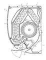
- Sectional drawing of the wall-mounted type indoor unit in the air conditioner which concerns on embodiment.
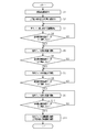
- the flowchart which shows operation
- the air conditioner according to the present embodiment is an air conditioner that includes a wall-mounted indoor unit 1 shown in FIG. 1 and an outdoor unit 20 (see FIG. 2) and performs a heat pump type cooling and heating operation.
- the wall-mounted indoor unit 1 has an elongated shape in one direction as a whole, and is mounted on the wall of the room so that the longitudinal direction is horizontal.
- the wall-mounted indoor unit 1 includes a casing 2, an indoor fan 3 housed in the casing 2, an indoor heat exchanger 4, left and right wind direction plates 5, up and down air direction plates 6, auxiliary up and down air direction plates 7, etc. Is equipped.
- the casing 2 has a substantially rectangular parallelepiped casing substrate 11 whose front surface is opened, and a front panel 12 which covers an open portion of the front surface of the casing substrate 11.
- the indoor suction port 13 which is a lattice-like opening which is long in the left-right direction is formed on the upper surface of the casing substrate 11, and the indoor air outlet 14 which is a rectangular opening which is long in the horizontal direction is formed on the lower surface of the casing substrate 11. Is formed.
- the air drawn in from the indoor suction port 13 by driving the indoor fan 3 disposed in the air flow path from the indoor suction port 13 to the indoor outlet 14 is After being heat-exchanged (ie, heated or cooled) in the indoor heat exchanger 4, the air is blown out from the indoor outlet 14 into the room.
- the left and right wind direction plate 5 is for adjusting the wind direction of the blown air blown out from the indoor outlet 14 in the left-right direction, and is provided on the inner side of the indoor outlet 14.
- the up and down wind direction plate 6 is for adjusting the wind direction of the blown air blown out from the indoor outlet 14 in the up and down direction.
- the vertical wind direction plate 6 is provided with a rotation center C ⁇ b> 1 at an intermediate position in the vertical direction of the indoor outlet 14.
- the position of the vertical wind direction plate 6 indicated by the solid line in FIG. 1 is the position where the vertical wind direction plate 6 faces the uppermost direction within the blowing direction adjustment range, and the position of the vertical wind direction plate 6 indicated by the two-dot chain line in FIG.
- the vertical wind direction plate 6 is at a position facing the lowermost direction.
- the uppermost direction in the blowing direction adjustment range of the wind direction of the up and down wind direction plate 6 is about horizontal position as in a general wall-mounted indoor unit.
- the vertical wind direction plate 6 can swing between a solid line position and a two-dot chain line position by a drive motor (not shown) according to an operation command from the user during the cooling operation or the heating operation. It is configured to be able to hold an appropriate position between the dotted line position.
- the auxiliary upper and lower air direction plates 7 are provided to prevent water droplets from adhering to the back surface of the upper and lower air direction plates 6 during the cooling operation, and are attached along the upper structural portion of the indoor outlet 14.
- the auxiliary vertical wind direction plate 7 is configured so that the blowing direction can be adjusted by the wind direction between the solid line position in FIG. 1 and the two-dot chain line position around the rotation center C2.
- the auxiliary upper and lower air direction plates 7 are controlled so as to automatically maintain the optimum position in conjunction with the position of the upper and lower air direction plates 6 in the blowing direction during the cooling operation.
- the auxiliary vertical wind direction plate 7 holds the wind direction at the position in the uppermost direction (solid line position in FIG. 1) in the blowing direction adjustment range.
- the description of the present embodiment relates to the operation at the start of the heating operation, the detailed description of the operation at the time of the cooling operation of the auxiliary vertical wind direction plate 7 is omitted.
- the vertical air flow direction plate 6 and the auxiliary vertical air flow direction plate 7 contact the upper structural portion of the indoor air outlet 14 above the position in the blowing direction adjustment range above the uppermost direction at the time of stopping the cooling operation and the heating operation. It is comprised so that the indoor blower outlet 14 can be closed by turning to the contact position (namely, closed position). As described above, the vertical air flow direction plate 6 doubles as a cover member for the indoor air outlet 14.
- the ventilation resistance of the indoor outlet 14 is maximized when the vertical wind direction plate 6 is at the uppermost position in the blowing direction adjustment range, as in a general wall-mounted indoor unit.
- the ventilation resistance of the indoor outlet 14 is smaller at a position lower than the position in the uppermost direction, and is minimum at an intermediate position between the position in the uppermost direction and the position in the lowermost direction. This is a phenomenon that occurs due to the bending state of the air flow passage and the size of the air flow space between the two wind direction plates. Therefore, the amount of air blown out from the indoor outlet 14 is when the up and down wind direction plate 6 is at the middle position within the blow out direction adjustment range with respect to when the up and down air direction plate 6 is at the uppermost position within the blow out direction adjustment range. Will increase.
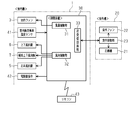
- control device 30 incorporated in the wall-mounted indoor unit 1 performs control relating to the overall operation of the air conditioner, and a storage unit that stores a predetermined control program, It is comprised from the arithmetic processing unit etc. which perform control based on this control program.
- the control device 30 further includes an air flow control unit 31 for limiting the air flow of the indoor fan 3 at the start of the heating operation, and a wind direction control unit 32 for controlling the wind direction of the vertical direction of the vertical wind direction plate 6 at the start of the heating operation. Is equipped.
- Control device 30 further includes a transmission / reception circuit unit 33 that communicates with outdoor unit 20 and the like.
- the indoor fan 3 and the indoor heat exchanger temperature sensor 41 are connected to the control device 30.
- the indoor fan 3 is a fan for indoor circulation that circulates the air heat-exchanged by the indoor heat exchanger 4 into the room, and the drive motor of this fan is controlled in rotational speed based on a command from the air volume control unit 31 It is controlled.
- the indoor heat exchanger temperature sensor 41 is attached to an appropriate position of the indoor heat exchanger 4 so that the average temperature of the indoor heat exchanger 4 can be detected as the indoor heat exchanger temperature Tr.
- the indoor heat exchanger temperature Tr detected by the indoor heat exchanger temperature sensor 41 is transmitted to the control device 30, and the air flow control of the indoor fan 3 by the air flow control unit 31 and the wind direction control of the up and down wind direction plate 6 by the wind direction control unit 32. It is used as basic data in
- the control unit 30 is connected to driving units for the vertical wind direction plate 6, the auxiliary vertical wind direction plate 7, and the horizontal wind direction plate 5, and these wind direction plates are configured to be controlled by the wind direction control unit 32. .
- an electric expansion valve 42 for controlling the refrigerant to the indoor heat exchanger 4 is connected to the control device 30. The electric expansion valve 42 is controlled in its opening degree by an instruction from the control device 30.
- a remote control 43 is attached to the wall-mounted indoor unit 1.
- the remote controller 43 functions as an operation unit for the air conditioner, and includes an operation switch for turning on and off the operation of the air conditioner, an operation mode selection unit, a setting unit for setting a set temperature of indoor air, and normal heating
- the air volume setting unit sets an air volume of the indoor fan during operation, and a display unit that displays the indoor temperature and the air volume of the indoor fan.
- the remote controller 43 is configured to wirelessly transmit the selected or set driving operation information to the control device 30.
- the outdoor unit 20 is equipped with a compressor 21 and an outdoor fan 22 and an outdoor control unit 23 for controlling these devices. Further, although not shown, the outdoor unit 20 is equipped with a four-way switching valve for switching the refrigerant circuit to a cooling cycle or a heating cycle. The four-way switching valve is switch-controlled by the outdoor control unit 23. Further, the control device 30 of the wall-mounted indoor unit 1 and the outdoor control unit 23 are electrically connected via the transmission / reception circuit unit 33, and the operation operation information from the remote control 43 received by the control device 30 is outdoor control. It is also output to the unit 23.
- step S1 When the heating operation start command is output by the remote controller 43 (step S1), the refrigerant circuit is switched to the heating cycle, and the operation of the compressor 21 and the outdoor fan 22 is started. Thereby, the heating operation of the air conditioner is started.
- the vertical air flow direction plate 6 and the auxiliary vertical air flow direction plate 7 disposed at the indoor air outlet 14 are opened from the closed position for closing the indoor air outlet 14, and the wind direction is at the uppermost position in the air blowing direction adjustment range. Rotate.
- the vertical wind direction plate 6 is restricted to maintain its position until the restriction of the wind direction is released (step S2).
- the auxiliary vertical wind direction plate 7 maintains the position in the uppermost direction in the blowing direction adjustment range during the heating operation, and other special control in the control of the blown air at the start of the heating operation. Will not take place.
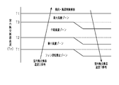
- the indoor heat exchanger temperature Tr is lower than the first switching temperature T1 in FIG. 4. That is, the air volume restriction of the indoor fan 3 is the fan operation prohibited zone shown in FIG. Therefore, in the state where the indoor heat exchanger temperature Tr is lower than the first switching temperature T1, the compressor 21 is operated with the indoor fan 3 stopped (step S3).
- step S4 when the indoor heat exchanger temperature Tr rises with time and reaches the first switching temperature T1 (YES in step S4), the air volume restriction of the indoor fan 3 is switched to the minimum air volume zone shown in FIG. The fan 3 is operated at the minimum air volume (step S5). In the case of NO at step S4, control device 30 returns to step S3.
- step S6 when the indoor heat exchanger temperature Tr rises with the passage of time and reaches the second switching temperature T2 (YES in step S6), the air volume restriction of the indoor fan 3 is switched to the intermediate air volume zone shown in FIG.
- the indoor fan 3 is operated at an intermediate air volume (step S7).
- control device 30 returns to step S5.
- step S8 when the indoor heat exchanger temperature Tr rises further with the passage of time and reaches the third switching temperature T3 (YES in step S8), the air volume restriction of the indoor fan 3 is switched to the maximum air volume zone shown in FIG. The indoor fan 3 is operated at the maximum air volume (step S9). If NO in step S8, control device 30 returns to step S7.
- step S10 when the indoor heat exchanger temperature Tr rises further with the passage of time and reaches the target set temperature Tt (YES in step S10), there is no concern that the occupants of the room may feel discomfort due to cold air blowing. It is assumed that the temperature of the blown air is rising, and the restriction of the wind direction of the up and down wind direction plate 6 and the restriction of the air flow of the indoor fan 3 are released (step S11). Thereby, the blowout air control at the start of the heating operation is finished. Therefore, after the indoor heat exchanger temperature Tr reaches the target set temperature Tt, a stable heating operation state is established.
- the indoor fan 3 is operated with the air volume set by the remote control 43 and the vertical wind direction plate 6 is set by the remote control 43 by canceling the wind direction restriction of the vertical air direction board 6 and the air volume restriction of the indoor fan 3. It moves to the wind direction and heating operation is done.
- the release of the wind direction restriction of the up and down air direction plate 6 is not performed when the indoor heat exchanger temperature Tr reaches the third switching temperature T3, and the target setting temperature higher than the third switching temperature T3
- Tt The reason for doing this when it comes to Tt is as follows. That is, when the wind direction of the up and down wind direction plate 6 is changed from the position in the blowing direction adjustment range from the position in the uppermost direction to the position in the downward direction, the amount of blown air increases, and the indoor heat exchanger temperature Tr decreases accordingly There is a risk of Similarly, release of the air volume restriction of the indoor fan 3 is not performed when the indoor heat exchanger temperature Tr reaches the third switching temperature T3, and the target setting temperature Tt that is higher than the third switching temperature T3 is reached. The reason for doing this is to make the heating speed up as fast as possible.
- switching temperatures T1, T2 and T3 set with respect to the indoor heat exchanger temperature Tr shown in FIG. 4 are indoor heat exchange against the temperature rise of the indoor heat exchanger temperature Tr. It is set so as to become lower at the time of temperature fall of the device temperature Tr. This is to avoid chattering of the indoor heat exchanger temperature sensor 41 and hunting of the air volume of the indoor fan 3.
- the switching temperature with respect to the indoor heat exchanger temperature Tr is switched to switch the air volume in stages.
- (T1, T2, T3) is set. Specifically, the switching temperature (T1, T2, T3) is set to be lower at the time of decrease of the indoor heat exchanger temperature Tr than at the time of increase of the indoor heat exchanger temperature Tr.
- the indoor outlet 14 is provided at the lower part of the wall-mounted indoor unit 1. Since the position of the vertical wind direction plate is limited so that the vertical wind direction plate 6 faces the uppermost direction in the blowing direction adjustment range at the start of the heating operation, the blowing of cold air can be effectively alleviated.
- the wind direction of the up and down wind direction plate 6 is set to the uppermost direction in the blowing direction adjustment range at the start of the heating operation.
- the wind direction of the up and down wind direction plate 6 may be an upper direction above the middle position instead of the uppermost direction in the blowing direction adjustment range. In this way, since the air blown out from the indoor outlet 14 forms an air flow that circulates in the upper part of the room, the blowing of cold air to the occupant can be alleviated.
- the auxiliary air flow direction plate 7 is provided at the indoor air outlet 14.
- the auxiliary air flow direction plate 7 may be omitted.
- the left and right air direction plates 5 are provided inside the indoor air outlet 14, but the left and right air direction plates 5 may be omitted.
- the vertical wind direction plate 6 doubles as the cover member of the indoor air outlet 14.
- the vertical wind direction plate 6 may not be such a dual use member but may be one which only changes the wind direction.
- the air volume switching of the indoor fan 3 is performed in three stages of the minimum air volume, the intermediate air volume, and the maximum wind rainfall.
- the air volume switching of the indoor fan 3 may be performed in two stages or four or more stages.
Landscapes
- Engineering & Computer Science (AREA)
- Mechanical Engineering (AREA)
- General Engineering & Computer Science (AREA)
- Chemical & Material Sciences (AREA)
- Combustion & Propulsion (AREA)
- Physics & Mathematics (AREA)
- Fluid Mechanics (AREA)
- Thermal Sciences (AREA)
- Air Conditioning Control Device (AREA)
Priority Applications (2)
| Application Number | Priority Date | Filing Date | Title |
|---|---|---|---|
| CN201880069361.8A CN111279136B (zh) | 2017-10-30 | 2018-09-28 | 空调机 |
| EP18874501.2A EP3705801B1 (de) | 2017-10-30 | 2018-09-28 | Klimaanlage |
Applications Claiming Priority (2)
| Application Number | Priority Date | Filing Date | Title |
|---|---|---|---|
| JP2017-209492 | 2017-10-30 | ||
| JP2017209492A JP6493486B1 (ja) | 2017-10-30 | 2017-10-30 | 空気調和機 |
Publications (1)
| Publication Number | Publication Date |
|---|---|
| WO2019087632A1 true WO2019087632A1 (ja) | 2019-05-09 |
Family
ID=65999153
Family Applications (1)
| Application Number | Title | Priority Date | Filing Date |
|---|---|---|---|
| PCT/JP2018/036229 Ceased WO2019087632A1 (ja) | 2017-10-30 | 2018-09-28 | 空気調和機 |
Country Status (4)
| Country | Link |
|---|---|
| EP (1) | EP3705801B1 (de) |
| JP (1) | JP6493486B1 (de) |
| CN (1) | CN111279136B (de) |
| WO (1) | WO2019087632A1 (de) |
Families Citing this family (4)
| Publication number | Priority date | Publication date | Assignee | Title |
|---|---|---|---|---|
| JP7192640B2 (ja) | 2019-04-23 | 2022-12-20 | 株式会社Soken | 超音波センサ |
| CN111706981A (zh) * | 2020-05-27 | 2020-09-25 | 广东纽恩泰新能源科技发展有限公司 | 一种空气源热泵热风机机组防冷风控制方法以及系统 |
| WO2024154930A1 (ko) * | 2023-01-19 | 2024-07-25 | 삼성전자주식회사 | 공기조화기 및 공기조화기의 제어 방법 |
| EP4414617A1 (de) * | 2023-02-09 | 2024-08-14 | Daikin Europe N.V. | Klimaanlage und verfahren zur steuerung einer klimaanlage |
Citations (10)
| Publication number | Priority date | Publication date | Assignee | Title |
|---|---|---|---|---|
| JPH0587391A (ja) * | 1991-09-27 | 1993-04-06 | Toshiba Corp | 空気調和装置の制御装置 |
| JPH09318144A (ja) * | 1996-05-31 | 1997-12-12 | Sanyo Electric Co Ltd | 空気調和機の風速制御方法 |
| JPH11264599A (ja) * | 1998-03-18 | 1999-09-28 | Fujitsu General Ltd | 空気調和機の制御方法 |
| JP2002174450A (ja) * | 2000-09-29 | 2002-06-21 | Daikin Ind Ltd | 空気調和装置 |
| JP2002340384A (ja) * | 2001-05-18 | 2002-11-27 | Fujitsu General Ltd | 空気調和機の制御方法 |
| JP2007303731A (ja) * | 2006-05-11 | 2007-11-22 | Matsushita Electric Ind Co Ltd | 空気調和機 |
| JP2007315641A (ja) * | 2006-05-24 | 2007-12-06 | Matsushita Electric Ind Co Ltd | 空気調和機 |
| JP2008292034A (ja) * | 2007-05-23 | 2008-12-04 | Panasonic Corp | 空気調和機 |
| JP2016038135A (ja) * | 2014-08-06 | 2016-03-22 | 三菱電機株式会社 | 空気調和機 |
| JP2016090113A (ja) * | 2014-10-31 | 2016-05-23 | ダイキン工業株式会社 | 空気調和機 |
Family Cites Families (13)
| Publication number | Priority date | Publication date | Assignee | Title |
|---|---|---|---|---|
| JPS59115930A (ja) * | 1982-12-22 | 1984-07-04 | Hitachi Ltd | ヒ−トポンプ式空気調和機の電気回路 |
| JP3522367B2 (ja) * | 1994-12-20 | 2004-04-26 | 松下電器産業株式会社 | 空気調和機の制御装置 |
| JP3495858B2 (ja) * | 1996-10-31 | 2004-02-09 | 東芝キヤリア株式会社 | 空気調和機 |
| JP2005090873A (ja) * | 2003-09-18 | 2005-04-07 | Matsushita Electric Ind Co Ltd | 空気調和機 |
| JP3686963B2 (ja) * | 2003-11-28 | 2005-08-24 | シャープ株式会社 | 空気調和機 |
| CN101968241A (zh) * | 2010-09-30 | 2011-02-09 | 广东美的电器股份有限公司 | 一种使用可燃制冷剂的空调器及其控制方法 |
| JP5250011B2 (ja) * | 2010-10-26 | 2013-07-31 | 三菱電機株式会社 | 空気調和機 |
| CN102563806B (zh) * | 2012-01-09 | 2014-10-29 | 美的集团股份有限公司 | 一种空调器出风温度的控制方法 |
| CN102721149A (zh) * | 2012-05-08 | 2012-10-10 | 广东美的制冷设备有限公司 | 一种空调器及其控制方法 |
| CN103388856B (zh) * | 2013-07-18 | 2015-09-30 | 广东美的暖通设备有限公司 | 多联机空调系统及其快速启动制热方法 |
| CN105987429A (zh) * | 2015-02-05 | 2016-10-05 | 佛山市禾才科技服务有限公司 | 一种多联机空调系统及其制热待机快速启动控制方法 |
| CN105042771B (zh) * | 2015-07-02 | 2017-12-26 | 珠海格力电器股份有限公司 | 空调制热开机防冷风控制方法及控制装置 |
| KR101746154B1 (ko) * | 2015-07-15 | 2017-06-13 | 한국과학기술연구원 | 공기조화 시스템 |
-
2017
- 2017-10-30 JP JP2017209492A patent/JP6493486B1/ja active Active
-
2018
- 2018-09-28 EP EP18874501.2A patent/EP3705801B1/de active Active
- 2018-09-28 CN CN201880069361.8A patent/CN111279136B/zh active Active
- 2018-09-28 WO PCT/JP2018/036229 patent/WO2019087632A1/ja not_active Ceased
Patent Citations (11)
| Publication number | Priority date | Publication date | Assignee | Title |
|---|---|---|---|---|
| JPH0587391A (ja) * | 1991-09-27 | 1993-04-06 | Toshiba Corp | 空気調和装置の制御装置 |
| JP3080187B2 (ja) | 1991-09-27 | 2000-08-21 | 東芝キヤリア株式会社 | 空気調和装置の制御装置 |
| JPH09318144A (ja) * | 1996-05-31 | 1997-12-12 | Sanyo Electric Co Ltd | 空気調和機の風速制御方法 |
| JPH11264599A (ja) * | 1998-03-18 | 1999-09-28 | Fujitsu General Ltd | 空気調和機の制御方法 |
| JP2002174450A (ja) * | 2000-09-29 | 2002-06-21 | Daikin Ind Ltd | 空気調和装置 |
| JP2002340384A (ja) * | 2001-05-18 | 2002-11-27 | Fujitsu General Ltd | 空気調和機の制御方法 |
| JP2007303731A (ja) * | 2006-05-11 | 2007-11-22 | Matsushita Electric Ind Co Ltd | 空気調和機 |
| JP2007315641A (ja) * | 2006-05-24 | 2007-12-06 | Matsushita Electric Ind Co Ltd | 空気調和機 |
| JP2008292034A (ja) * | 2007-05-23 | 2008-12-04 | Panasonic Corp | 空気調和機 |
| JP2016038135A (ja) * | 2014-08-06 | 2016-03-22 | 三菱電機株式会社 | 空気調和機 |
| JP2016090113A (ja) * | 2014-10-31 | 2016-05-23 | ダイキン工業株式会社 | 空気調和機 |
Non-Patent Citations (1)
| Title |
|---|
| See also references of EP3705801A4 |
Also Published As
| Publication number | Publication date |
|---|---|
| CN111279136A (zh) | 2020-06-12 |
| CN111279136B (zh) | 2022-03-29 |
| EP3705801A4 (de) | 2020-12-30 |
| JP6493486B1 (ja) | 2019-04-03 |
| EP3705801B1 (de) | 2022-01-19 |
| JP2019082277A (ja) | 2019-05-30 |
| EP3705801A1 (de) | 2020-09-09 |
Similar Documents
| Publication | Publication Date | Title |
|---|---|---|
| CN103629839B (zh) | 空调机 | |
| JP5003829B2 (ja) | 空気調和機 | |
| JP5847034B2 (ja) | 空気調和機 | |
| JP5507231B2 (ja) | 空気調和機 | |
| CN107166532A (zh) | 壁挂式空调室内机及其控制方法 | |
| JP6072561B2 (ja) | 空気調和システム | |
| JP6493178B2 (ja) | 空気調和機 | |
| CN103154621B (zh) | 空调机 | |
| WO2019087632A1 (ja) | 空気調和機 | |
| JP2011196666A (ja) | 空気調和機 | |
| JP6808999B2 (ja) | 空気調和機 | |
| GB2527193A (en) | Indoor unit and air conditioning apparatus | |
| AU2004286118B2 (en) | Air conditioner and control method thereof | |
| JP6211892B2 (ja) | 空気調和機 | |
| CN101932885B (zh) | 空调机 | |
| WO2018079476A1 (ja) | 空調室内機 | |
| JP2004076974A (ja) | 空気調和機および空気調和機の制御方法 | |
| JP2011127800A (ja) | 空気調和機 | |
| JP6540336B2 (ja) | 空気調和機 | |
| KR20090055071A (ko) | 공기조화기의 제어방법 | |
| WO2014050337A1 (ja) | 空気調和機 | |
| JP2004076973A (ja) | 空気調和機および空気調和機の制御方法 | |
| JP6171410B2 (ja) | 空気調和機 | |
| WO2016063437A1 (ja) | 空気調和装置 | |
| EP4414617A1 (de) | Klimaanlage und verfahren zur steuerung einer klimaanlage |
Legal Events
| Date | Code | Title | Description |
|---|---|---|---|
| 121 | Ep: the epo has been informed by wipo that ep was designated in this application |
Ref document number: 18874501 Country of ref document: EP Kind code of ref document: A1 |
|
| NENP | Non-entry into the national phase |
Ref country code: DE |
|
| ENP | Entry into the national phase |
Ref document number: 2018874501 Country of ref document: EP Effective date: 20200602 |