WO2019088024A1 - Dispositif de détermination d'état de surface de route et système de pneu le comprenant - Google Patents
Dispositif de détermination d'état de surface de route et système de pneu le comprenant Download PDFInfo
- Publication number
- WO2019088024A1 WO2019088024A1 PCT/JP2018/040125 JP2018040125W WO2019088024A1 WO 2019088024 A1 WO2019088024 A1 WO 2019088024A1 JP 2018040125 W JP2018040125 W JP 2018040125W WO 2019088024 A1 WO2019088024 A1 WO 2019088024A1
- Authority
- WO
- WIPO (PCT)
- Prior art keywords
- data
- road surface
- tire
- learning
- unit
- Prior art date
- Legal status (The legal status is an assumption and is not a legal conclusion. Google has not performed a legal analysis and makes no representation as to the accuracy of the status listed.)
- Ceased
Links
Images













Classifications
-
- B—PERFORMING OPERATIONS; TRANSPORTING
- B60—VEHICLES IN GENERAL
- B60C—VEHICLE TYRES; TYRE INFLATION; TYRE CHANGING; CONNECTING VALVES TO INFLATABLE ELASTIC BODIES IN GENERAL; DEVICES OR ARRANGEMENTS RELATED TO TYRES
- B60C19/00—Tyre parts or constructions not otherwise provided for
-
- B—PERFORMING OPERATIONS; TRANSPORTING
- B60—VEHICLES IN GENERAL
- B60W—CONJOINT CONTROL OF VEHICLE SUB-UNITS OF DIFFERENT TYPE OR DIFFERENT FUNCTION; CONTROL SYSTEMS SPECIALLY ADAPTED FOR HYBRID VEHICLES; ROAD VEHICLE DRIVE CONTROL SYSTEMS FOR PURPOSES NOT RELATED TO THE CONTROL OF A PARTICULAR SUB-UNIT
- B60W40/00—Estimation or calculation of non-directly measurable driving parameters for road vehicle drive control systems not related to the control of a particular sub unit, e.g. by using mathematical models
- B60W40/02—Estimation or calculation of non-directly measurable driving parameters for road vehicle drive control systems not related to the control of a particular sub unit, e.g. by using mathematical models related to ambient conditions
- B60W40/06—Road conditions
- B60W40/068—Road friction coefficient
-
- G—PHYSICS
- G01—MEASURING; TESTING
- G01W—METEOROLOGY
- G01W1/00—Meteorology
Definitions
- the present disclosure detects a vibration received by a tire and generates a road surface data indicating a road surface state based on the vibration data.
- the road surface state includes a vehicle side system that receives the road surface data and estimates the road surface state.
- the present invention relates to a determination device and a tire system provided with the same.
- Patent Document 1 there is provided a road surface condition determining method including an acceleration sensor on the back surface of the tire tread, detecting the vibration applied to the tire by the acceleration sensor, and estimating the road surface condition based on the detection result of the vibration. Proposed.
- this road surface condition determination method a feature vector is extracted from the tire's vibration waveform detected by the acceleration sensor, and the similarity between the extracted feature vector and all the support vectors stored for each type of road surface is calculated. , Determine the road surface condition.
- the algorithm for road surface condition determination is offline, that is, it is a prior learning type, and for example, support vectors are acquired by learning using a support vector machine, and the stored data is used for determination of the road surface condition.
- the road surface condition can not be appropriately determined only by the stored data of the support vector learned in advance.
- An object of the present disclosure is to provide a road surface state determination device capable of appropriately determining a road surface state even in a situation where it is not possible to cope only with stored data learned in advance, and a tire system having the same.
- the road surface state determining device includes a tire side device and a vehicle body side system, and the tire side device detects a vibration detection unit that outputs a detection signal according to the magnitude of the vibration of the tire.
- the vehicle body system includes: a waveform processing unit that generates road surface data indicating a road surface condition that appears in the waveform of the signal; and a first data communication unit that transmits the road surface data.
- a second data communication unit for receiving the data, a storage unit for storing the teacher data, a road surface determination unit for determining the road surface condition on the traveling road surface of the vehicle based on the road surface data and the teacher data; It is judged whether it is the situation where the learning operation of teacher data should be performed while it is judged whether it is the situation where the learning operation of teacher data should be performed based on the peripheral device to acquire and environmental data. Based on the results, and includes a environment judgment unit for outputting a request signal to the tire side unit, a through the second data communication unit. Then, when the first data communication unit receives the request signal, the tire device generates the road surface data in the waveform processing unit, and transmits the road surface data to the vehicle body system through the first data communication unit. The system is updated to the teacher data stored in the storage unit when the update data of the teacher data is learned and calculated by machine learning using the road surface data transmitted from the tire side device and the condition type indicated by the environment data. Save the data including the above as new teacher data.
- the road surface state determination apparatus configured as described above, environmental data is acquired by a peripheral device provided in the vehicle, and it is determined that learning of teacher data is to be performed based on the environmental data. Then, in a situation where learning of teacher data is to be performed, learning calculation of teacher data is performed using road surface data linked to the type of situation. Thus, the teacher data can be updated according to the situation in addition to the teacher data stored as the initial data in the storage unit.
- the parenthesized reference symbol attached to each component etc. shows an example of the correspondence of the component etc. and the specific component etc. as described in the embodiment to be described later.
- FIG. 1 It is a figure showing the block configuration in the vehicles mounting state of the tire device to which the road surface state distinction device concerning a 1st embodiment is applied. It is a block diagram showing details of a tire side device and a vehicle body side system. It is a cross-sectional schematic diagram of the tire in which the tire side apparatus was attached. It is an output voltage waveform figure of the acceleration acquisition part at the time of tire rotation. It is a figure which shows a mode that the detection signal of the acceleration acquisition part was divided for every time window of predetermined time width
- FIG. It is a flowchart of the data transmission process which a tire side apparatus performs. It is a flowchart of the road surface state discrimination
- a tire device 100 having a road surface state determination function according to the present embodiment will be described with reference to FIGS. 1 to 12.
- the tire device 100 according to the present embodiment determines the road surface state during traveling based on the vibration applied to the ground contact surface of the tire provided on each wheel of the vehicle, and notifies of the danger of the vehicle or the vehicle based on the road surface state. It performs exercise control and the like.
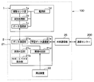
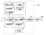
- the tire device 100 is configured to have a tire side device 1 provided on the wheel side and a vehicle body side system 2 including each part provided on the vehicle body side.
- the vehicle body side system 2 includes a receiver 21, a peripheral device 22, an electronic control unit for brake control (hereinafter referred to as a brake ECU) 23, a notification device 24, and the like.
- the part of the tire device 100 that realizes the road surface state determination function corresponds to the road surface state determination device.
- the receiver 21 and the peripheral device 22 of the tire side device 1 and the vehicle body side system 2 constitute a road surface state determining device.
- the tire device 100 of the present embodiment transmits data (hereinafter referred to as road surface data) according to the road surface condition on the traveling road surface of the tire 3 from the tire device 1 and receives the road surface data by the receiver 21 To determine the In addition, the tire device 100 transmits the determination result of the road surface state in the receiver 21 to the notification device 24, and causes the notification device 24 to notify the determination result of the road surface state. This makes it possible to convey the road surface condition to the driver, for example, a dry road, a wet road, or a frozen road, and to warn the driver if the road surface is slippery. In addition, the tire device 100 transmits a road surface state to the brake ECU 23 or the like that performs vehicle motion control so that vehicle motion control for avoiding a danger is performed.
- road surface data data (hereinafter referred to as road surface data) according to the road surface condition on the traveling road surface of the tire 3 from the tire device 1 and receives the road surface data by the receiver 21 To determine the In addition, the tire device 100 transmits the determination result
- the tire side device 1 and the receiver 21 are configured as follows.
- the tire side device 1 is disposed in each of the tires 3 so that bidirectional communication with the vehicle side system 2 is enabled.
- the tire-side device 1 is configured to include a vibration sensor unit 1a, a waveform processing unit 1b, a data communication unit 1c, and a power supply unit 1d, as shown in FIG. , Provided on the back side of the tread 31 of the tire 3.
- the vibration sensor unit 1 a constitutes a vibration detection unit for detecting the vibration applied to the tire 3.
- the vibration sensor unit 1a is configured by an acceleration sensor.
- the vibration sensor unit 1a is an acceleration sensor
- the vibration sensor unit 1a contacts the circular track drawn by the tire-side device 1, that is, the tire shown by arrow X in FIG.
- An acceleration detection signal is output as a detection signal corresponding to the magnitude of the tangential vibration.
- the acceleration acquiring unit 10 generates, as a detection signal, an output voltage in which one of the two directions indicated by the arrow X is positive and the opposite direction is negative.
- the vibration sensor unit 1a performs acceleration detection at a predetermined sampling cycle which is set to a cycle shorter than one rotation of the tire 3, and outputs it as a detection signal.
- vibration sensor part 1a In addition, although the case where the vibration of a tire tangential direction was detected with vibration sensor part 1a was explained here, the same thing can be performed, even if it detects vibration of other directions, for example, tire radial direction.
- the waveform processing unit 1b is configured by a known microcomputer including a CPU, ROM, RAM, I / O, etc., performs signal processing of the detection signal according to a program stored in the ROM or the like, and displays the road surface condition appearing in the detection signal.
- the road surface data to be shown is generated.
- the road surface data includes data including a feature amount of tire vibration and data including a raw waveform of a detection signal in addition to the feature amount.
- the waveform processing unit 1b uses the detection signal output from the vibration sensor unit 1a as a detection signal representing vibration data in the tire tangential direction, and performs waveform processing of the vibration waveform indicated by the detection signal. Extract the feature value of tire vibration.
- the feature amount of the tire G is extracted by performing signal processing on a detection signal of the acceleration of the tire 3 (hereinafter referred to as a tire G).
- the waveform processing unit 1b acquires a raw waveform that is the detection signal of the vibration sensor unit 1a itself, performs signal processing such as noise removal as necessary, and digitizes it (hereinafter, the raw waveform is digitized) Is called raw waveform data). Then, the waveform processing unit 1b transmits the data including the extracted feature amount or the feature amount including raw waveform data to the data communication unit 1c as road surface data.
- the details of the feature quantities referred to here will be described later.
- the waveform processing unit 1b controls data transmission from the data communication unit 1c, and transmits road surface data to the data communication unit 1c at a timing when it is desired to perform data transmission, whereby data from the data communication unit 1c is transmitted. Allow communication to take place.
- the waveform processing unit 1b extracts the feature amount of the tire G each time the tire 3 makes one rotation, and the data communication unit 1c at a rate of once or plural times every one rotation or plural rotations of the tire 3.
- the road surface data is transmitted to
- the waveform processing unit 1b transmits, to the data communication unit 1c, road surface data including the feature amount of the tire G extracted during one rotation of the tire 3 when transmitting the road surface data to the data communication unit 1c. ing.
- the road surface includes raw waveform data in addition to the feature amount of the tire G extracted during one rotation of the tire 3 at that time. Data is transmitted to data communication unit 1c.
- the data communication unit 1 c is a part that constitutes the first transmission / reception unit, and performs data communication with the data communication unit 21 a of the receiver 21 in the vehicle body side system 2 described later.
- the data communication unit 1c is configured to be able to perform two-way communication with the data communication unit 21a.
- the data communication unit 1c is described as one configuration here, but may be configured separately for the transmission unit and the reception unit.
- Various forms of bi-directional communication can be applied.
- Bluetooth communication including BLE (abbreviation of Bluetooth Low Energy) communication, wireless LAN such as wifi (abbreviation of Local Area Network), Sub-GHz communication, ultra wide band Communication, ZigBee, etc. can be applied.
- BLE abbreviation of Bluetooth Low Energy
- wireless LAN such as wifi (abbreviation of Local Area Network)
- Sub-GHz communication ultra wide band Communication
- ZigBee etc.
- Bluetooth is a registered trademark.
- the data communication unit 1c transmits road surface data at that timing.
- the timing of data transmission from the data communication unit 1c is controlled by the waveform processing unit 1b. Then, each time road surface data is sent from the waveform processing unit 1b each time the tire 3 makes one rotation or multiple rotations, or when a request signal from the vehicle body side system 2 is received, the data communication unit 1c Data transmission is to be performed.
- the power supply unit 1 d serves as a power supply of the tire-side device 1 and supplies the power to the respective units provided in the tire-side device 1 so that the respective units can be operated.
- the power supply unit 1 d is configured of, for example, a battery such as a button battery.
- the receiver 21, the peripheral device 22, the brake ECU 23, the notification device 24, and the external communication device 25 constituting the vehicle body side system 2 are driven when a start switch such as an ignition switch (not shown) is turned on.
- the receiver 21 is configured to have a data communication unit 21a, a support vector storage unit 21b, a road surface determination unit 21c, an environment determination unit 21d, and a learning data communication unit 21e. Also, as shown in FIGS. 1 and 2, the receiver 21 can perform data communication with the external communication device 25, and exchanges data with the communication center 200 through the external communication device 25. It is also possible to
- the data communication unit 21a is a part that configures the second transmission / reception unit, and includes road surface data including the feature amount transmitted from the data communication unit 1c of the tire-side device 1 or road surface data including raw waveform data in addition to the feature amount. It plays a role of receiving and communicating to the road surface determination unit 21c.
- the support vector storage unit 21b stores and stores support vectors, and stores, for example, support vectors for each type of road surface.
- the support vector is a feature that serves as an example, and is obtained, for example, by learning using a support vector machine.
- the vehicle equipped with the tire-side device 1 is run experimentally for each type of road surface, and at that time the feature quantity extracted by the feature quantity extraction unit 11a is learned for a predetermined number of tire rotations, and a typical feature quantity among them What is extracted a predetermined number of times is taken as a support vector. For example, feature amounts for one million rotations are learned for each type of road surface, and typical feature amounts for 100 rotations are extracted therefrom as support vectors.
- the support vector storage unit 21b stores the initial support vector at the time of delivery, but also stores the support vector for updating from the learning data communication unit 21e. Therefore, the support vector storage unit 21b updates the support vector.
- the support vector for updating is added to the support vector stored in advance, and the support vector can be used as a new support vector after updating.
- the update of the support vector is not limited to the method of adding the support vector for update to the support vector stored in advance, but at least a part of the support vector stored in advance as the support vector for update It may be a method of rewriting or replacing.
- the road surface determination unit 21c is configured by a known microcomputer including a CPU, a ROM, a RAM, an I / O, and the like, and performs various processes according to a program stored in the ROM or the like to determine the road surface state. Specifically, the road surface determination unit 21c determines the road surface state by comparing the feature amount included in the road surface data transmitted from the waveform processing unit 1b with the support vector stored in the support vector storage unit 21b. ing.
- the feature amount included in the road surface data received this time is compared with the support vector for each type of road surface, and the road surface of the support vector having the closest feature amount is determined as the current traveling road surface.
- the road surface determination unit 21c determines the road surface condition
- the road surface determination unit 21c transmits the determined road surface condition to the notification device 24, and notifies the driver of the road surface condition from the notification device 24 as needed.
- the driver can keep in mind the driving corresponding to the road surface condition, and the danger of the vehicle can be avoided.
- the road surface state determined through the notification device 24 may be always displayed, or the road surface state is determined only when the driving needs to be performed more carefully, such as a wet road or a frozen road. The status may be displayed to warn the driver.
- the road surface state is transmitted from the receiver 21 to the ECU for executing the vehicle movement control such as the brake ECU 23, and the vehicle movement control is performed based on the transmitted road surface state.
- the environment determination unit 21d determines the situation in which the support vector should be learned based on the environment data obtained from the peripheral device 22, and based on the determination result, a request signal for requesting the road surface data to the tire-side device 1 Output For example, the environment determination unit 21d determines whether or not a support vector should be learned. When the environment determining unit 21d determines that the support vector should be learned, the environment determining unit 21d outputs a request signal to the tire-side device 1 through the data communication unit 21a.
- the situation in which the support vector should be learned means that the condition of the road surface of the traveling road surface of the vehicle has changed based on the environmental data, and the condition different from the learning condition in which the support vector is extracted.
- the support vector is a characteristic feature extracted from the learning result under a specific condition, so even if the actual driving condition is different from the driving condition at the time of learning, It is preferable to do learning. For example, in the case of a road surface type different from the stored support vector learning conditions, the support vector should be learned as a new road surface type.
- the road surface type is the same as the stored support vector learning conditions, depending on the actual traveling environment or traveling method of the vehicle, or the change in tire type, air pressure or wear amount, season or The appropriate support vector may change with temperature or weather.
- the detection signal of the vibration sensor unit 1a changes from the expected one, and thus the learned support vector may be in an inappropriate state. .
- Such a case is referred to as "a situation in which support vector should be learned".
- the learning data communication unit 21e acquires road surface data including raw waveform data in addition to the feature amount received by the data communication unit 21a. Then, the learning data communication unit 21e links the data of the type of the situation determined to be the situation where the support vector should be learned by the environment determination unit 21d with the received road surface data, and further, the ID information of the own vehicle. , Etc., and transmits it to the external communication device 25. In this way, the communication center 200 provided outside the vehicle through the external communication unit 25 can distinguish the vehicle from other vehicles in addition to the road surface data including raw waveform data in addition to the feature amount and the data of the type of situation. Data is transmitted.
- the learning data communication unit 21 e acquires the support vector for update sent from the communication center 200 through the external communication device 25, the learning data communication unit 21 e transmits it to the support vector storage unit 21 b.
- the support vector storage unit 21b further adds the support vector obtained as a learning result to the support vector stored so far, and uses it as the new support vector after the update.
- the peripheral device 22 is configured by various devices provided in the vehicle, and as described above, acquires environmental data related to the road surface condition used for recognizing a situation where support vector learning should be performed, such as a change in road surface condition, It plays a role of conveying it to the environment determination unit 21d.
- an on-vehicle camera, a brake ECU 23, a wiper device, a load sensor, a tire pressure monitoring system (hereinafter referred to as TPMS), and the like are applied as the peripheral device 22.
- the environment determination unit 21d analyzes the image data of the on-vehicle camera, and can determine the road surface condition, the actual traveling environment of the vehicle, the traveling method, the weather, and the like based on the analysis result.
- the brake ECU 23 may perform various controls such as ABS (abbreviation of Antilock BrakeSystem) and VSC (abbreviation of Vehicle stability control), and may estimate the road surface friction coefficient or the road surface state.
- the environment determination unit 21d can acquire information on the road surface state from the brake ECU 23, and can determine the road surface state based on the information.
- the environment determination unit 21d acquires information indicating that the wiper drive is being performed from the control unit of the wiper apparatus, and based on it, it can be determined that the road surface state is, for example, a wet state or weather.
- the road surface type is the same as the learning condition of the stored support vector based on the judgment result of the road surface state and the weather, the traveling environment, the traveling method, the weather, etc. are different, or It is possible to identify the type of road surface different from the learning condition. This makes it possible to learn a support vector that takes into consideration various parameters such as the type of road surface, traveling environment, traveling method, and weather.
- a known method may be applied to the estimation of the road surface state based on the analysis of the image data acquired by the on-vehicle camera and the estimation of the road surface state by the brake ECU 23.
- the load applied to the tire 3 can be acquired by the load sensor, and the tire pressure can be acquired by the TPMS. Even if the road surface state is the same as the state in which the support vector is learned, the state quantity may change according to the size of the load applied to the tire 3 and tire information such as the tire pressure. In these cases, even if the road surface type is the same as the stored support vector learning condition, the support vector may not be appropriate. Therefore, by obtaining tire information as environmental data from a load sensor or TPMS, it becomes possible to learn a feature amount taking into consideration tire information as well as the type of road surface.
- the peripheral device 22 may be any device other than the above-described example as long as it can acquire environmental data that can be used to recognize the situation in which the support vector should be learned.
- environmental data For example, weather information, temperature information, season information, area information, road surface freezing information and the like may be acquired by a navigation system (not shown) and the like, and they may be transmitted to the environment determination unit 21d as environment data.
- the type of tire 3 and the wearing condition can also be environmental data as tire information.
- the change in the type of the tire 3 may be registered in the receiver 21 through an operation switch or the like (not shown), and the wear state may be estimated from the travel distance obtained from a meter ECU or the like (not shown) .
- the brake ECU 23 constitutes a braking control device that performs various brake control. Specifically, the brake ECU 23 controls the braking force by increasing or decreasing the wheel cylinder pressure by driving an actuator for controlling the brake fluid pressure. The brake ECU 23 can also control the braking force of each wheel independently. When the road surface condition is transmitted from the receiver 21 by the brake ECU 23, the braking force is controlled as the vehicle motion control based thereon. For example, the brake ECU 23 weakens the braking force generated with respect to the amount of brake operation by the driver, as compared with a dry road surface, when it indicates that the road surface state transmitted is a frozen road. Thereby, it is possible to suppress the wheel slip and to avoid the danger of the vehicle.
- the brake ECU 23 may perform estimation of the road surface friction coefficient and estimation of the road surface state. In that case, the brake ECU 23 transmits information on the road surface state to the environment determination unit 21 d.
- the notification device 24 can also be configured by a buzzer, a voice guidance device, or the like. In that case, the notification device 24 can aurally notify the driver of the road surface condition by buzzer sound or voice guidance.
- the meter display was mentioned as the example as the alerting
- the external communication device 25 is a device for performing data communication with the communication center 200 via a wireless network such as DCM (Data Communication Module).
- the external communication device 25 transmits the road surface data including raw waveform data and data of the type of situation in addition to the feature amount from the receiver 21 and transmits it to the communication center 200 described later. Play.
- the external communication device 25 also plays a role of receiving the updated data of the support vector transmitted from the communication center 200 and transmitting it to the receiver 21.
- each part which comprises the vehicle body side system 2 is connected through in-vehicle LAN (abbreviation of Local AreaNetwork) by CAN (abbreviation of Controller AreaNetwork) communication etc., for example. Therefore, each part can communicate information with each other through the in-vehicle LAN. Furthermore, in the case of the present embodiment, by using the communication center 200 provided outside the vehicle in addition to the tire device 100, a tire system is configured that can further enhance learning data and update support vectors.
- the communication center 200 plays a role as a learning device that realizes a function as a support vector machine that creates a support vector by learning and a function that provides updated data of the created support vector.
- the communication center 200 performs two-way communication with the vehicle body side system 2 using a computer provided outside the vehicle to perform learning calculation of the support vector, and the result of the learning calculation on the vehicle side Play a role in That is, the communication center 200 corresponds to a computer providing a service in cloud computing (hereinafter, referred to as a cloud).
- a cloud a computer providing a service in cloud computing
- the communication center 200 also stores a support vector as initial data before update stored in the support vector storage unit 21b of each vehicle.
- the communication center 200 To the communication center 200, road surface data linked with the type of the situation determined to be the situation where the support vector should be learned from the receiver 21 is delivered through the external communication device 25. Therefore, the communication center 200 reads feature amounts and raw waveform data from road surface data for each type of situation, analyzes them, and performs various operations to learn and calculate support vectors for each type of situation. Then, when the support vector is acquired as a result of the learning operation, the communication center 200 adds it to the support vector stored as initial data and stores it, as well as transmits data to each vehicle side, and the external communication device 25 to the receiver 21. Based on this, the support vector in the support vector storage unit 21b is updated.
- the tire system including the tire device 100 and the communication center 200 according to the present embodiment is configured.
- the feature amount referred to here is an amount indicating the feature of the vibration applied to the tire 3 acquired by the vibration sensor unit 1a, and is expressed as a feature vector, for example.
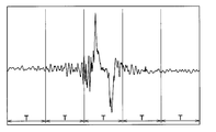
- An output voltage waveform of a detection signal of the vibration sensor unit 1a at the time of tire rotation is, for example, a waveform shown in FIG.
- the output voltage of the vibration sensor unit 1a reaches its maximum value at the start of ground contact when the portion of the tread 31 corresponding to the location of the vibration sensor unit 1a starts to be grounded as the tire 3 rotates.
- the peak value at the start of grounding where the output voltage of the vibration sensor unit 1a has a maximum value is referred to as a first peak value.
- a portion of the tread 31 corresponding to the location where the vibration sensor unit 1 a is disposed is grounded.
- Output voltage has a local minimum value.
- the peak value at the end of grounding where the output voltage of the vibration sensor unit 1a has a local minimum value is referred to as a second peak value.
- the peak value of the output voltage of the vibration sensor unit 1a at the above timing is due to the following reason. That is, when the portion of the tread 31 corresponding to the location where the vibration sensor unit 1a is placed on the ground as the tire 3 rotates, the portion of the tire 3 having a substantially cylindrical surface in the vicinity of the vibration sensor unit 1a It is pressed and deformed into a planar shape. By receiving the impact at this time, the output voltage of the vibration sensor unit 1a takes a first peak value. In addition, when the portion of the tread 31 corresponding to the location where the vibration sensor unit 1a is disposed is separated from the ground contact surface with the rotation of the tire 3, the tire 3 is released from pressure in the vicinity of the vibration sensor unit 1a.
- the output voltage of the vibration sensor unit 1a takes a second peak value. In this way, the output voltage of the vibration sensor unit 1a takes the first and second peak values at the start of grounding and at the end of grounding, respectively. Further, since the direction of the impact when the tire 3 is pressed and the direction of the impact when released from the pressing are opposite, the sign of the output voltage is also the opposite.
- step-in area an instant at which a portion of the tire tread 31 corresponding to the location where the vibration sensor unit 1a is disposed contacts the road surface
- step-out area an instant at which it is separated from the road surface
- step-in area includes the timing at which the first peak value is obtained
- step-out area includes the timing at which the second peak value is obtained.
- the area in front of the stepping area is the area before the stepping area, and the area from the stepping area to the kicking area, that is, the portion of the tire tread 31 corresponding to the location where the vibration sensor portion 1a is in contact.
- "Region after kicking out” is taken as "area after kicking out”.
- five areas R1 to R5 are “pre-step-in area”, “step-in area”, “kick-out front area”, “kick-out area”, and “post-kick out area” in the detection signal in this order. It is shown as.
- the vibration generated in the tire 3 fluctuates in each of the divided areas, and the detection signal of the vibration sensor unit 1a changes, so that the frequency analysis of the detection signal of the vibration sensor unit 1a in each area is performed.
- Detects the road surface condition on the traveling road surface of the vehicle For example, in a slippery road surface condition such as a snowy road, the shear force at the time of kicking is reduced, so the band value selected from the 1 kHz to 4 kHz band becomes smaller in the kicking out region R4 and the after kicking out region R5.
- the band value selected from the 1 kHz to 4 kHz band becomes smaller in the kicking out region R4 and the after kicking out region R5.
- the waveform processing unit 1b detects the detection signal of the vibration sensor unit 1a for one rotation of the tire 3 which has a continuous time axis waveform, as shown in FIG.
- the feature quantity is extracted by dividing into a plurality of sections and performing frequency analysis in each section. Specifically, the power spectrum value in each frequency band, that is, the vibration level in the specific frequency band is determined by performing frequency analysis in each section, and this power spectrum value is used as the feature amount.
- the number of the division divided by the time window of time width T is a value which changes according to the rotational speed of the tire 3 in more detail according to the vehicle speed.
- the number of sections for one tire rotation is n (where n is a natural number).
- the power obtained by passing the detection signal of each section through five band pass filters of a plurality of specific frequency bands for example, 0 to 1 kHz, 1 to 2 kHz, 2 to 3 kHz, 3 to 4 kHz, or 4 to 5 kHz
- This feature quantity is called a feature vector
- a feature vector Xi of a section i (where i is a natural number of 1 ⁇ i ⁇ n) is represented by aik when the power spectrum value of each specific frequency band is indicated by aik It is expressed as in the following equation as a matrix having.
- This determinant X is an expression representing the feature amount for one rotation of the tire.
- the waveform processing unit 1 b extracts the feature quantity represented by the determinant X by frequency analysis of the detection signal of the vibration sensor unit 1 a.
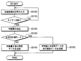
- the waveform processing unit 1 b performs data transmission processing shown in FIG. 6. This process is performed every predetermined control cycle.
- step S100 input processing of the detection signal of the vibration sensor unit 1a is performed. This process is continued in the subsequent step S110 for a period until the tire 3 makes one revolution.
- the process proceeds to the subsequent step S120, and the feature amount of the time axis waveform of the detection signal of the vibration sensor unit 1a for one rotation of the input tire is extracted.
- the fact that the tire 3 has made one rotation is determined based on the time axis waveform of the detection signal of the vibration sensor unit 1a. That is, since the detection signal draws the time axis waveform shown in FIG. 4, one rotation of the tire 3 can be grasped by confirming the first peak value and the second peak value of the detection signal.
- the vibration level of the detection signal of the vibration sensor unit 1a is smaller than the threshold value, it is detected as a period less susceptible to the road surface condition among the "pre-depression region” and the "after kicking region".
- the signal may not be input.
- step S120 The extraction of the feature amount performed in step S120 is performed by the method as described above.
- step S130 it is determined whether the raw waveform measurement mode is in effect.
- the raw waveform measurement mode is a mode in which transmission of the raw waveform of the detection signal of the vibration sensor unit 1a is required in addition to the feature amount as road surface data.
- the request signal is transmitted through the data communication unit 21a.
- the waveform processing unit 1b determines that the raw waveform measurement mode is in effect.
- step S140 If a negative determination is made here, it is not a situation where learning of support vectors is to be performed, so the process proceeds to step S140, and in the case of the current control cycle to execute data transmission for determination of the road surface state which is normally performed.
- the road surface data including the extracted feature amount is transmitted to the data communication unit 1c.
- road surface data including the feature amount is transmitted from the data communication unit 1c.
- step S130 In addition, in the case where an affirmative determination is made in step S130, it is a situation in which support vector learning should be performed. Therefore, the process proceeds to step S150, and road data including raw waveform data is transmitted to data communication unit 1c in addition to the feature value extracted in the current control cycle, in order to execute data transmission for learning support vectors. . Accordingly, road surface data including raw waveform data is transmitted from the data communication unit 1c in addition to the feature amount.
- the road surface condition determination process shown in FIG. 7 the environment determination process shown in FIG. 8, the learning data transmission process shown in FIG. 9, and the learning data update process shown in FIG.
- the road surface condition determination process is performed by the road surface determination unit 21c
- the environment determination process, the learning data transmission process, and the learning data update process are performed by the environment determination unit 21d or the learning data communication unit 21e.
- the respective units provided in 21 may cooperate to execute each process. These processes are executed at each control cycle determined for each process by timer interrupt process or the like.
- the communication center 200 executes a learning process shown in FIG. This process is also executed in the communication center 200 every predetermined control cycle.
- the environment determination process, the learning data transmission process, the learning process, and the learning data update process correspond to each other. Specifically, the learning data transmission process is performed corresponding to the environment determination process, the learning process is performed corresponding to the learning data transmission process, and the learning data update process is performed corresponding to the learning process. Therefore, in the following, after the road surface condition determination processing is described, the environment determination processing, the learning data transmission processing, the learning processing, and the learning data update processing will be described in this order.
- step S200 data reception process is performed in step S200. This process is performed when the data communication unit 21a receives road surface data, and the road surface determination unit 21c takes in the road surface data. When the data communication unit 21a is not performing data reception, the road surface determination unit 21c ends the process without taking in any road surface data.
- step S210 it is determined whether data of road surface data including the feature amount has been received. If received, the process proceeds to step S220. If not received, the process proceeds to step S200. The process of S210 is repeated. Here, it is determined that the road surface data including the feature amount has been received, and it is assumed that even if the road surface data including the raw waveform data is received, it is not received. However, since road surface data including raw waveform data can also be used to determine the road surface condition by extracting data relating to the feature amount, even road surface data including raw waveform data is received As well.
- step S220 determines the road surface state.
- the determination of the road surface state is performed by comparing the feature amount included in the received road surface data with the support vector for each type of road surface stored in the road surface determination unit 21c. For example, the feature amount is determined as the degree of similarity with all the support vectors for each type of road surface, and the road surface of the support vector with the highest degree of similarity is determined as the current road surface.
- calculation of the similarity between the feature amount and all the support vectors for each type of road surface can be performed by the following method.
- the determinant of the feature is X (r)
- the determinant of the support vector is X (s)
- the power spectrum value a ik serving as each element of each determinant Let be represented by a (r) ik , a (s) ik .
- the determinant X (r) of the feature amount and the determinant X (s) of the support vector are expressed as follows.
- the similarity indicates the degree of similarity between the feature quantities indicated by the two determinants and the support vector, which means that the higher the similarity, the more similar.
- the road surface determination unit 21c obtains the similarity using the kernel method, and determines the road surface state based on the similarity.
- the inner product of the determinant X (r) of the feature amount and the determinant X (s) of the support vector in other words, the feature vector Xi of sections divided by each time window of a predetermined time width T in the feature space The distance between the coordinates indicated by is calculated and used as the similarity.
- the time axis waveform at the time of rotation of the tire 3 and the time axis waveform of the support vector each have a predetermined time width T Divide into each section.
- T time width
- n 5 and i is represented by 1 ⁇ i ⁇ 5.
- the feature vector Xi of each section when the tire 3 is rotating this time is Xi (r)
- the feature vector of each section of the support vector is Xi (s).
- feature vectors are obtained by dividing into five specific frequency bands. Therefore, the feature vector Xi of each section is represented in a six-dimensional space aligned with the time axis, and the distance between the coordinates indicated by the feature vectors of the sections is the distance between the coordinates in the six-dimensional space.
- the distance between coordinates indicated by the feature vector of each section is smaller as the feature amount and the support vector are similar and larger as they are not similar, so the smaller the distance is, the higher the similarity is, and the distance is The larger the value, the lower the degree of similarity.
- the distance K yz between coordinates indicated by the feature vector of the compartment between time-division determined for all sections and calculates the distance K yz sum K total of all sections fraction, the sum K total similarity It is used as the corresponding value.
- the total sum K total is compared with a predetermined threshold Th, and it is determined that the degree of similarity is low if the total sum K total is larger than the threshold Th, and the degree of similarity is high if the total K total is smaller than the threshold Th.
- the calculation of the similarity is performed on all the support vectors, and it is determined that the type of the road surface corresponding to the support vector having the highest similarity is the road condition currently being traveled. In this way, road surface condition determination can be performed.
- the sum K total of the distance K yz between two coordinates indicated by the feature vector of each section is used as a value corresponding to the degree of similarity
- another parameter may be used as a parameter indicating the degree of similarity.
- an average distance K ave which is an average value of the distances K yz obtained by dividing the total sum K total by the number of sections can be used.
- various kernel functions can be used to determine the degree of similarity.
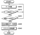
- step S300 data reception processing is performed in step S300. This process is performed by the environment determination unit 21 d receiving environment data from the peripheral device 22. When the environment determination unit 21d is not receiving data, the environment determination unit 21d ends the process without capturing any environment data.
- step S310 determines whether data has been received. If received, the process proceeds to step S320, and if not received, the processes of steps S300 and S310 are repeated until reception.
- step S320 it is determined based on the environmental data whether it is a situation where learning of support vectors is to be performed.
- the affirmative determination is made, and the process proceeds to the processing after step S330, and when not corresponding, the negative determination is repeated and the processing of steps S300 and S310 is repeated.
- step S330 data of the type of situation when it is determined that the “condition for which support vector should be learned” is stored. This data is stored, for example, until it is overwritten by the affirmative determination in step S320 and the process of step S330 being executed. Then, the process proceeds to step S340, instructs the data communication unit 21a to transmit a request signal, and ends the process. Thereby, a request signal is transmitted to each tire side device 1 through the data communication unit 21a.
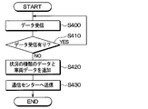
- step S400 data reception processing is performed in step S400.
- This process is performed by the learning data communication unit 21e taking in the road surface data when the data communication unit 21a receives the road surface data.
- the learning data communication unit 21e ends the process without taking in road surface data.
- step S410 it is determined whether data has been received. If it has been received, the process proceeds to step S420. If it has not been received, the processes of steps S400 and S410 are repeated until it is received. Here, it is determined that the road surface data including the raw waveform data is received in addition to the feature amount, and it is assumed that the road surface data not including the raw waveform data is not received.
- step S420 in addition to road surface data when it is determined that the situation should be learned, data of the situation where the environment determination unit 21d should learn the support vector stored in the above-described environment determination process Create data to which vehicle data such as own vehicle ID information is added. Thereafter, the process proceeds to step S430, and the data created in step S420 is transmitted from the learning data communication unit 21e to the communication center 200.
- road surface data including raw waveform data in addition to the feature amount, data of the type of situation, and vehicle data for distinction from other vehicles to the communication center 200 provided outside the vehicle through the external communication device 25. Is transmitted. Then, the road surface data, the type of situation data, and the vehicle data are stored in the communication center 200.
- step S500 data reception processing is performed in step S500.
- a process of receiving the data transmitted in step S430 of FIG. 9 is performed.
- the process proceeds to step S510, and based on the data received in step S500, the feature amount and raw waveform data are read from the road surface data for each type of situation for each vehicle, and they are analyzed and various calculations are performed. Learn and operate support vectors by type.
- step S520 it is determined whether there is a need for data update based on the learning calculation result. For example, when the amount of data collected for a learning operation is small and a support vector is not obtained, or when the result of the learning operation has not changed from the currently stored support vector, the need for data update is required. It is determined that there is no sex. Then, as in the case where a support vector is obtained and a support vector different from the currently stored support vector is obtained, when an affirmative determination is made in step S520, the process proceeds to step S530. As a result, data transmission of the support vector linked to the type of the situation is performed together with the vehicle data for determining the own data to the vehicle side.
- the communication center 200 also stores the road surface state indicated by the vehicle data, the support vector linked to the type of the situation, and the road surface data. As a result, it is possible to accumulate learning data of support vectors for each vehicle data, that is, for each vehicle, data of the road surface condition of the traveling road surface of the vehicle, and the like, and it becomes possible to effectively utilize the accumulated data. If the negative determination is made in step S520, the process ends.
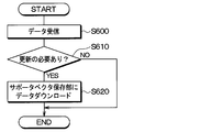
- step S600 data reception processing is performed in step S600.
- a process of receiving the data transmitted in step S530 of FIG. 10 is performed. Thereafter, the process proceeds to step S610, and based on the data received in step S600, it is determined whether it is necessary to update the support vector currently stored in the support vector storage unit 21b. If the received data includes a support vector different from the support vector currently stored in the support vector storage unit 21b, it is determined that the data needs to be updated, and the process proceeds to step S620.
- step 620 by transmitting data to the support vector storage unit 21b, the data stored in the support vector storage unit 21b is updated, and the process ends.
- the data is updated when a negative determination is made in step S610. End the process.
- the present embodiment is such that the support vector is stored in the tire side device 1 in the first embodiment, and the other parts are the same as the first embodiment, and therefore, parts different from the first embodiment. Will be explained only.
- the tire side device 1 is provided with the support vector storage unit 1 e, and the tire side device 1 can determine the road surface state.
- the data of the support vector stored in advance in the support vector storage unit 1 e is the same as the support vector storage unit 21 b described in the first embodiment.
- the road surface state may be determined based on the feature amount extracted from the detection signal of the vibration sensor unit 1a and the storage data of the support vector storage unit 1e. it can. Then, data indicating the determination result of the road surface condition is transmitted from the data communication unit 1c to the receiver 21, and the road surface determination unit 21c determines the road surface condition based on the determination result indicated by the data transmitted from the tire device 1. It is notified to the notification device 24.
- road surface data including raw waveform data is transmitted from the tire side device 1 in addition to the feature amount. It is transmitted to the communication center 200 through the communication device 25.
- the communication center 200 is used as the cloud providing source computer to perform a learning operation of the support vector, and the result of the learning operation is transmitted to the receiver 21 through the external communication device 25.
- the data of the support vector to be updated is the tire side device from the data communication unit 21a. It is transmitted to 1. Then, in addition to the support vector stored in the support vector storage unit 1e, data of a new support vector is stored.
- the tire side device 1 basically, the tire side device 1, the receiver 21, and the communication center 200 perform the same processes as in the first embodiment except that the above-described operation is performed, that is, The same processing as in FIGS. 6 to 11 is performed.
- step S120 in FIG. 6 the road surface state is also determined in addition to the extraction of the feature amount, and in step S140, the road surface data including the feature amount may also be sent. I am sending data.
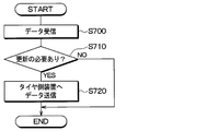
- processing shown in FIG. 14 is performed instead of the processing shown in FIG. Specifically, in steps S700 to S710 shown in FIG. 14, processing similar to steps S600 to S610 shown in FIG. 11 is performed, and then in step S720, transmission of support vector data to be updated to the tire side device 1 is performed. Do.
- step S710 it is determined whether the support vector currently stored in the support vector storage unit 1e needs to be updated. With regard to this, it is necessary to include data representing that the content to be updated is included in the data transmitted from the communication center 200, and to update the data in the receiver 21 when the data is included. It may be determined to be present.
- Third Embodiment A third embodiment will be described.
- the present embodiment effectively utilizes the data stored in the communication center 200 as described in the first embodiment, and the storage of data in the communication center 200 is the same as in the first and second embodiments. Because of this, only differences from the first and second embodiments will be described.
- a support vector serving as learning data is accumulated in the communication center 200. Therefore, in the case of a vehicle of the same vehicle type or a vehicle having the same tire, there is a possibility that various data stored in the communication center 200 can be diverted. For this reason, when various data transmitted from the vehicle and the calculated support vector are stored in the communication center 200, the data can be diverted to other vehicles. Specifically, another vehicle performs the processing shown in FIGS. 15 and 16 to divert data.
- the tire side device 1 and the vehicle body side system 2 as shown in FIG. 2 are also provided for other vehicles. Therefore, in the tire side device 1, the process shown in FIG. 6 is performed, and in the vehicle body side system 2, the processes shown in FIGS. 7 to 9 and 11 are performed.
- the communication center 200 executes the process shown in FIG. In addition to that, the vehicle body side system 2 executes the download request process shown in FIG. 15, and the communication center 200 executes the data download process shown in FIG.
- step S800 the vehicle body side system 2 performs data reception processing in step S800.
- This process is the same process as step S200 in FIG.
- step S810 it is determined whether the data is different from the learned data. For example, the similarity between the feature amount included in the received data and all the support vectors stored in the support vector storage unit 21b is calculated. Then, if there is only one having a low degree of similarity, it is considered that the support vector that has already been learned is not included as a road surface state of the road surface currently being traveled in accordance with the type of the road surface. It is judged that it is different from the data. Also, if the environmental data obtained from the peripheral device 22 instead of the data received from the tire-side device 1 in step S800 indicates a condition different from the learning condition from which the learned support vector has been extracted, You may judge that it is different.
- step S810 if a negative determination is made in step S810, the process ends as it is, and if a positive determination is made, the process proceeds to step S820.
- step S820 a request signal of learning data is transmitted to the communication center 200, which is a cloud providing source computer, together with vehicle data for distinguishing it from other vehicles.
- vehicle data as in the above, it is sufficient if the data can be used to distinguish between the host vehicle and other vehicles, but here, by including more detailed data such as the type of the tire 3, the situation of the host vehicle can be further improved. It is possible to request corresponding learning data.
- data of the type of situation is also transmitted, it becomes possible to request learning data according to the type of situation. Thereafter, learning data is sent from the communication center 200 based on the processing shown in FIG. 16 described later, so that the learning data is downloaded in step S830.
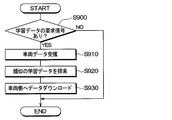
- step S900 it is determined whether a request signal for learning data from the vehicle side has been received. If a negative determination is made here, the process ends as it is, and if a positive determination is made, the process proceeds to step S 910. If a request signal for learning data is transmitted in step S820 described above, an affirmative determination is made in this step.
- step S910 a process of receiving vehicle data sent together with a request signal for learning data is performed. Then, the process proceeds to step S920, and learning data similar to the vehicle data is searched. Among the data stored in the communication center 200, for example, learning data of a vehicle of the same vehicle type, a vehicle of the same tire, or a vehicle corresponding to both of them is searched as similar learning data. Thereafter, the process proceeds to step S 930, and transmission of learning data of various data and support vectors stored in the communication center 200 is performed to cause the vehicle that has transmitted the request signal of learning data to download the learning data. Do. Also at this time, vehicle data is sent along with the learning data, so that a vehicle to be downloaded can be specified.
- the communication center 200 since the communication center 200 also stores data on the road surface condition of the traveling surface of the preceding vehicle, etc., if the data is also transmitted to other vehicles, the other vehicles are traveling on their own. It becomes possible to know in advance the data of the road surface condition even for the non-road surface. In that case, in another vehicle, it is not necessary to acquire data for determining the road surface state.
- the tire-side device 1 since the tire-side device 1 is provided with the support vector storage unit 1e, it may be determined in the tire-side device 1 whether or not it is different from the learned data. . Then, if different from the learned data, the request signal may be transmitted from the tire device 1 to the vehicle body system 2.
- the vehicle body side system 2 when it becomes a condition different from the learning condition in which the support vector is extracted, it is preferable to obtain learning data under that condition as "a situation where learning of the support vector should be performed". .
- a specific example of the “condition in which support vector should be learned” will be described.
- the vehicle body side system 2 when it is determined by the vehicle body side system 2 that “the support vector should be learned” based on the environment data of the peripheral device 22, the vehicle body side system 2 sends a response to the tire device 1.
- an instruction to transmit road surface data such as raw waveform data is issued.
- this is merely an example, and the method described in the first embodiment may be used.
- road surface data such as raw waveform data
- the vehicle body side system 2 determines that "the situation where support vector should be learned"
- the road surface data already received is received. It may be in the form of communication to the communication center 200.
- the environment determination unit 21d and the like execute the processes shown in FIGS. 17 to 24. These processes are performed by dividing the environment determination process shown in FIG. 8 described in the first embodiment into the contents to be determined, and are executed here as an independent flow, for example, as a timer interrupt process. However, it may be a single flow.
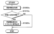
- step S1000 a acquisition processing of temperature information of the outside air temperature is performed. This process is performed, for example, by using the navigation system as the peripheral device 22 to acquire temperature information. Then, the process proceeds to step S1010a, and it is determined whether the outside air temperature acquired earlier is 0 ° C. or less. That is, if the environment in which the support vector has been learned is, for example, an environmental temperature of about 25 ° C., and if the environment is such that a temperature difference from the environmental temperature occurs, the outside air temperature is 0 ° C. or less In this case, it is considered as "a situation in which support vector should be learned". If an affirmative determination is made here, the process proceeds to step S1020a, a request signal of a learning start instruction is output to the tire device 1 or the communication center 200 side, and the process is ended.
- step S1000 b weather information acquisition processing is performed. This process is also performed, for example, by using the navigation system as the peripheral device 22 and acquiring weather information. Then, the process proceeds to step S1010b, and it is determined whether the weather acquired earlier is the weather without learning experience, for example, heavy rain, strong wind, or the like. That is, the environment where the amount of rainfall and the wind speed were higher than the situation where the amount of rainfall and the wind speed were learned was the situation where the amount of rainfall per unit time was less than the predetermined amount and the wind speed was less than the predetermined value. In this case, it is considered as "the situation where support vector should be learned".
- step S1020b executes the same process as step S1020a described above, and ends the process.
- heavy rain and strong wind are mentioned as an example as an example of weather information here, of course, it is applicable also to other information.
- step S1000 c seasonal information acquisition processing is performed in step S1000 c.
- This process is also performed, for example, by using the navigation system as the peripheral device 22 and acquiring current seasonal information or acquiring current date and time information.
- the process proceeds to step S1010c, and it is determined whether the current season acquired earlier is a season different from the learned season. That is, in the case where the support vector has been learned, for example, in the spring season, when the current season is in an environment such as winter, it is regarded as the “condition in which support vector should be learned”. If an affirmative determination is made here, the process proceeds to step S1020c, performs the same process as step S1020a described above, and ends the process.
- step S1000 d tire information acquisition processing is performed in step S1000 d.
- This process is performed by reading the content registered in the receiver 21 when the type of the tire 3 is changed, for example, by using the receiver 21 as the peripheral device 22. Then, the process proceeds to step S1010d, and it is determined whether the type of the tire 3 indicated by the previously acquired tire information is a different type from that learned, for example, whether there is a change from a genuine tire. That is, in the situation where the support vector is learned, for example, when the tire is a genuine tire, when the type of the current tire 3 is not a genuine tire, it is considered as "a situation where learning of the support vector should be performed".
- step S1020d the same process as step S1020a described above is performed, and the process is ended.
- the tire information can also be newly added as learned tire information.
- newly learned tire information may be included in the type of the tire 3 at the time of learning.
- step S1000 e a tire air pressure acquisition process is performed. This process is performed by using the TPMS as the peripheral device 22 and acquiring tire pressure information as tire information from the TPMS, for example. Then, the process proceeds to step S1010e, and it is determined whether the previously-obtained tire pressure is less than or equal to a predetermined threshold value. That is, in the situation in which the support vector has been learned, for example, when the tire pressure is appropriate, if the current tire pressure has dropped to a threshold value or less, it is determined that "the situation in which support vector should be learned". If an affirmative determination is made here, the process proceeds to step S1020e, the same process as step S1020a described above is performed, and the process is ended.
- step S1000 f road surface state acquisition processing is performed in step S1000 f.
- This processing is performed, for example, by using the on-vehicle camera or the brake ECU 23 as the peripheral device 22 to acquire an estimation result of the road surface condition based on analysis of image data acquired by the on-vehicle camera or acquiring an estimation result of the road surface condition by the brake ECU 23 To be done.
- the process proceeds to step S1010f, and it is determined whether the road surface state acquired earlier is a non-learned road surface with no learning experience. That is, since the situation in which the support vector has been learned is, for example, a learning road surface such as a dry road surface such as asphalt road, a wet road surface, a frozen road, a snow road etc. " If an affirmative determination is made here, the process proceeds to step S1020f, the same process as step S1020a described above is performed, and the process is ended.
- step S1000 g detection processing of remaining grooves of the tire 3 corresponding to the tire worn state is performed.
- the receiver 21 and the meter ECU are registered as peripheral devices 22 and the fact that tire replacement has been performed is registered in the receiver 21 and the travel distance from the time of registration is acquired from the meter ECU. It is performed by calculating the remaining groove of.
- the process proceeds to step S1010g, and it is determined whether the remaining groove of the tire 3 acquired earlier is equal to or less than the threshold. That is, since the remaining grooves of the tire 3 are sufficiently present in the situation in which the support vector is learned, when the remaining grooves are equal to or less than the threshold value, the “condition in which the support vector should be learned” is set. If an affirmative determination is made here, the process proceeds to step S1020g, the same process as step S1020a described above is performed, and the process is ended.
- acceleration / deceleration information acquisition processing is performed in step S1000 h.
- This process is performed, for example, by using the brake ECU 23 and the meter ECU as the peripheral device 22 and calculating the acceleration / deceleration from the vehicle speed handled by them.
- the process proceeds to step S1010h, and it is determined whether the acceleration / deceleration acquired earlier is outside the predetermined threshold range. That is, since the acceleration / deceleration is within the predetermined threshold range in the situation where the support vector is learned, when the acceleration / deceleration is outside the threshold range, it is considered as "the situation where the support vector should be learned". If an affirmative determination is made here, the process proceeds to step S1020h, executes the same processing as step S1020a described above, and ends the processing.
- the environment determination process is performed, and when the request signal of the learning start instruction is output in steps S1020a to S1020h, the tire device 1, the vehicle body system 2 and the communication center 200 perform various processes based thereon. Run.
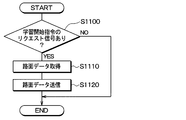
- step S1100 it is determined whether or not there is a request signal for learning start instruction. As described above, when the request signal of the learning start instruction is output from the vehicle body side system 2, an affirmative determination is made in this step, and the process proceeds to step S1110. Then, after road surface data including raw waveform data for one rotation of the tire is acquired, the process proceeds to step S1120, and the road surface data is transmitted to the vehicle body side system 2 as data.
- the process of step S1110 can be performed by the same method as each process of FIG. 6 described above.
- step S1200 reception processing of road surface data including raw waveform data transmitted from the tire-side device 1 is performed, and then, in step S1210, it is determined whether road surface data is acquired.
- step S1210 it is determined whether road surface data is acquired.
- the process ends. If it can be received, the process advances to step S 1220 to execute processing of transmitting the received road surface data as learning data to the communication center 200 in order to upload it to the communication center 200.
- step S1300 it is determined whether there is a request signal for learning start instruction. As described above, when the request signal of the learning start instruction is output from the vehicle body side system 2, an affirmative determination is made in this step, and the process proceeds to step S1310. Then, it is determined whether or not road surface data including raw waveform data transmitted from the vehicle body side system 2 is acquired, and if acquired, the process proceeds to step S 1320 to start learning and when learning is completed, the result is used as the vehicle body side system Transfer to 2 and download to the support vector storage unit 21b.
- the processing method of the communication center 200 at this time is the same as steps S510 to S530 in FIG. 10, and based on that, the method in which the vehicle body side system 2 downloads data to the support vector storage unit 21b is also the step S600 to FIG. Similar to S620.
- This embodiment detects a change in the road surface condition in the tire side device 1 in the first to fourth embodiments, and when there is a change in the road surface condition, transmits the road surface change to the vehicle body side system 2 To start learning.
- the other aspects of the present embodiment are the same as those of the first to fourth embodiments, and therefore, only different parts from the first to fourth embodiments will be described.
- the tire side device 1 detects a change in the road surface state based on the detection signal of the vibration sensor unit 1a, and transmits the change to the vehicle body side system 2. Specifically, the tire side device 1 executes a road surface change detection process shown in FIG.
- step S1400 input processing of the detection signal of the vibration sensor unit 1a is performed, and in step S1410, a period until the tire 3 makes one rotation is continued.
- the process proceeds to step S1420, and the feature amount of the time axis waveform of the detection signal of the acceleration acquisition unit 10 for one rotation of the input tire is extracted as the current feature amount. Do.
- the feature quantity extraction method at this time is the same as step S120 in FIG.
- step S1430 the similarity is determined for the current feature amount and the previous feature amount by the method described in step S220 of FIG. It is determined whether or not there is.
- step S1440 the fact that there is a change in the road surface condition is stored in step S1440.
- step S1450 the current feature amount is stored as the previous feature amount in the feature amount storage unit 11b, and the process is ended.
- step S1500 it is determined whether it has been determined that there has been a change in the road surface state. This determination is performed based on whether or not there is a change in the road surface state stored in step S1440 of FIG. 27 described above. If an affirmative determination is made here, the process proceeds to step S1510, and data indicating that the road surface state has changed is transmitted to the vehicle body side system 2 together with the road surface data including the feature amount and raw waveform data this time. Then, if a negative determination is made here, the process proceeds to step S1520, and road surface data including the feature amount this time is transmitted.
- each process shown in FIGS. 7 to 11 described in the first embodiment is executed.
- Each of these processes is substantially the same as in the first embodiment, but at step S320 in FIG. 8, data indicating that there is a change in the road surface condition has been transmitted from the tire-side device 1. It is determined that "the situation where learning of the vector should be performed".
- the tire side device 1 detects a change in the road surface state, and transmits it to the vehicle body side system 2 as "a situation where learning of support vector should be performed", and causes the communication center 200 to learn the support vector. It can also be done.
- the vibration sensor unit 1a constituting the vibration detection unit is constituted by an acceleration sensor
- other elements capable of detecting vibration for example, piezoelectric elements etc. It can also be done.
- the road surface data including the feature amount and the raw waveform data is sent to the communication center 200, only one of the feature amount and the raw waveform data may be sent. Further, integral value data of vibration waveforms of the five regions R1 to R5 included in vibration data during one rotation of the tire 3 may be sent to the communication center 200 as road surface data.
- another ECU such as the brake ECU 23 or the like determines the degree of similarity, determines the road surface state, or determines an instruction signal state at any place of the vehicle body side system 2. Transmission may be performed.
- the communication center 200 is used for the support vector learning operation. This is because, for example, the amount of data at the time of performing the learning operation is enormous, and for example, the receiver 21 is provided with a function of performing the learning operation of the support vector so that each vehicle can carry out the learning operation. It is good.
- the communication center 200 it is also possible to perform the learning calculation of the support vector in consideration of various information which can not be obtained by each vehicle, for example, a road surface condition determined based on data of other vehicles. Therefore, by using the communication center 200, it is possible to perform learning calculation of the support vector used for updating more accurately.
- the bidirectional communication is performed between the tire device 1 and the receiver 21 in each of the above embodiments, the bidirectional communication may not necessarily be performed.
- the receiver 21 is configured to include the support vector storage unit 21b, when the support vector is to be updated based on the environmental data of the peripheral device 22, the support is supported based on the road surface data from the tire device 1.
- Perform vector learning operation The learning calculation of the support vector may be performed by the communication center 200 or may be performed by the receiver 21 or the like by providing the receiver 21 with a function to perform the learning calculation. As described above, it is possible to perform the learning calculation and update of the support vector even as one-way communication in which data communication can be performed only from the tire-side device 1 to the receiver 21.
- a support vector is taken as an example as teacher data, but teacher data is updated by other known machine learning.
- the present disclosure is also applicable to
- tire side apparatus 1 was provided with respect to each of the some tire 3 in said each embodiment, what is necessary is just to be provided in at least one.
Landscapes
- Engineering & Computer Science (AREA)
- Mechanical Engineering (AREA)
- Environmental & Geological Engineering (AREA)
- Mathematical Physics (AREA)
- Transportation (AREA)
- Physics & Mathematics (AREA)
- Automation & Control Theory (AREA)
- Life Sciences & Earth Sciences (AREA)
- Atmospheric Sciences (AREA)
- Biodiversity & Conservation Biology (AREA)
- Ecology (AREA)
- Environmental Sciences (AREA)
- Tires In General (AREA)
- Control Of Driving Devices And Active Controlling Of Vehicle (AREA)
Abstract
Selon l'invention, un système côté caisse de véhicule (2) acquiert des données d'environnement avec un dispositif périphérique (22) disposé sur un véhicule, et, sur la base des données d'environnement, détermine qu'il existe une situation dans laquelle un vecteur de support devrait être appris. Dans les cas où il existe une situation dans laquelle des données d'apprentissage devraient être apprises, le calcul d'apprentissage des données d'apprentissage est exécuté par l'utilisation des données de surface de route associées au type de situation. Par conséquent, il est possible de continuer à mettre à jour, dans une unité de stockage (21b), des données d'apprentissage en fonction de la situation, en plus des données d'apprentissage stockées à titre de données initiales.
Priority Applications (1)
| Application Number | Priority Date | Filing Date | Title |
|---|---|---|---|
| US16/859,799 US11549809B2 (en) | 2017-10-30 | 2020-04-27 | Road surface state determination device and tire system |
Applications Claiming Priority (4)
| Application Number | Priority Date | Filing Date | Title |
|---|---|---|---|
| JP2017-209402 | 2017-10-30 | ||
| JP2017209402 | 2017-10-30 | ||
| JP2018113705A JP6733707B2 (ja) | 2017-10-30 | 2018-06-14 | 路面状態判別装置およびそれを備えたタイヤシステム |
| JP2018-113705 | 2018-06-14 |
Related Child Applications (1)
| Application Number | Title | Priority Date | Filing Date |
|---|---|---|---|
| US16/859,799 Continuation US11549809B2 (en) | 2017-10-30 | 2020-04-27 | Road surface state determination device and tire system |
Publications (1)
| Publication Number | Publication Date |
|---|---|
| WO2019088024A1 true WO2019088024A1 (fr) | 2019-05-09 |
Family
ID=66333086
Family Applications (1)
| Application Number | Title | Priority Date | Filing Date |
|---|---|---|---|
| PCT/JP2018/040125 Ceased WO2019088024A1 (fr) | 2017-10-30 | 2018-10-29 | Dispositif de détermination d'état de surface de route et système de pneu le comprenant |
Country Status (1)
| Country | Link |
|---|---|
| WO (1) | WO2019088024A1 (fr) |
Cited By (8)
| Publication number | Priority date | Publication date | Assignee | Title |
|---|---|---|---|---|
| CN110182215A (zh) * | 2019-05-23 | 2019-08-30 | 南京航空航天大学 | 一种汽车经济性巡航控制方法及装置 |
| WO2021045051A1 (fr) * | 2019-09-04 | 2021-03-11 | 株式会社デンソー | Dispositif de pneumatique |
| WO2021080011A1 (fr) * | 2019-10-25 | 2021-04-29 | 株式会社デンソー | Dispositif de commande |
| WO2021210229A1 (fr) * | 2020-04-14 | 2021-10-21 | Kyb株式会社 | Procédé pour générer un modèle instruit et dispositif de détermination d'état de surface de route |
| US11198336B2 (en) | 2017-10-30 | 2021-12-14 | Denso Corporation | Transmission and receiving arrangement for a tire pressure detection device |
| US11376901B2 (en) * | 2018-03-02 | 2022-07-05 | Denso Corporation | Road surface condition determination device performing sensing based on different sensing conditions |
| WO2023189971A1 (fr) * | 2022-03-31 | 2023-10-05 | Kyb株式会社 | Dispositif de calcul, procédé de calcul et programme |
| CN119428712A (zh) * | 2024-11-29 | 2025-02-14 | 山东华盛橡胶有限公司 | 一种用于湿滑路面的新能源轮胎磨损程度检测方法及设备 |
Citations (3)
| Publication number | Priority date | Publication date | Assignee | Title |
|---|---|---|---|---|
| JP2002340863A (ja) * | 2001-05-15 | 2002-11-27 | Toyota Central Res & Dev Lab Inc | 路面判定装置及びシステム |
| JP2007055284A (ja) * | 2005-08-22 | 2007-03-08 | Bridgestone Corp | 路面状態推定方法、路面状態推定用タイヤ、路面状態推定装置、及び、車両制御装置 |
| JP2010095135A (ja) * | 2008-10-16 | 2010-04-30 | Toyota Motor Corp | 車輪振動抽出装置及び路面状態推定装置 |
-
2018
- 2018-10-29 WO PCT/JP2018/040125 patent/WO2019088024A1/fr not_active Ceased
Patent Citations (3)
| Publication number | Priority date | Publication date | Assignee | Title |
|---|---|---|---|---|
| JP2002340863A (ja) * | 2001-05-15 | 2002-11-27 | Toyota Central Res & Dev Lab Inc | 路面判定装置及びシステム |
| JP2007055284A (ja) * | 2005-08-22 | 2007-03-08 | Bridgestone Corp | 路面状態推定方法、路面状態推定用タイヤ、路面状態推定装置、及び、車両制御装置 |
| JP2010095135A (ja) * | 2008-10-16 | 2010-04-30 | Toyota Motor Corp | 車輪振動抽出装置及び路面状態推定装置 |
Cited By (18)
| Publication number | Priority date | Publication date | Assignee | Title |
|---|---|---|---|---|
| US11198336B2 (en) | 2017-10-30 | 2021-12-14 | Denso Corporation | Transmission and receiving arrangement for a tire pressure detection device |
| US11376901B2 (en) * | 2018-03-02 | 2022-07-05 | Denso Corporation | Road surface condition determination device performing sensing based on different sensing conditions |
| CN110182215A (zh) * | 2019-05-23 | 2019-08-30 | 南京航空航天大学 | 一种汽车经济性巡航控制方法及装置 |
| WO2021045051A1 (fr) * | 2019-09-04 | 2021-03-11 | 株式会社デンソー | Dispositif de pneumatique |
| JP2021037885A (ja) * | 2019-09-04 | 2021-03-11 | 株式会社Soken | タイヤ装置 |
| JP7367404B2 (ja) | 2019-09-04 | 2023-10-24 | 株式会社Soken | タイヤ装置 |
| JPWO2021080011A1 (fr) * | 2019-10-25 | 2021-04-29 | ||
| JP7169461B2 (ja) | 2019-10-25 | 2022-11-10 | 株式会社デンソー | 制御装置 |
| WO2021080011A1 (fr) * | 2019-10-25 | 2021-04-29 | 株式会社デンソー | Dispositif de commande |
| JP2021169705A (ja) * | 2020-04-14 | 2021-10-28 | Kyb株式会社 | 学習済みモデル生成方法および路面性状判定装置 |
| WO2021210229A1 (fr) * | 2020-04-14 | 2021-10-21 | Kyb株式会社 | Procédé pour générer un modèle instruit et dispositif de détermination d'état de surface de route |
| CN115398062A (zh) * | 2020-04-14 | 2022-11-25 | Kyb株式会社 | 已学习模型的生成方法及路面特征判定装置 |
| JP7377154B2 (ja) | 2020-04-14 | 2023-11-09 | カヤバ株式会社 | 路面性状判定装置 |
| CN115398062B (zh) * | 2020-04-14 | 2024-10-11 | Kyb株式会社 | 路面特征判定装置 |
| WO2023189971A1 (fr) * | 2022-03-31 | 2023-10-05 | Kyb株式会社 | Dispositif de calcul, procédé de calcul et programme |
| JP2023151409A (ja) * | 2022-03-31 | 2023-10-16 | Kyb株式会社 | 演算装置、演算方法及びプログラム |
| JP7478181B2 (ja) | 2022-03-31 | 2024-05-02 | カヤバ株式会社 | 演算装置、演算方法及びプログラム |
| CN119428712A (zh) * | 2024-11-29 | 2025-02-14 | 山东华盛橡胶有限公司 | 一种用于湿滑路面的新能源轮胎磨损程度检测方法及设备 |
Similar Documents
| Publication | Publication Date | Title |
|---|---|---|
| JP2019081531A (ja) | 路面状態判別装置およびそれを備えたタイヤシステム | |
| WO2019088024A1 (fr) | Dispositif de détermination d'état de surface de route et système de pneu le comprenant | |
| WO2019142868A1 (fr) | Dispositif de détermination d'état de surface de route et système de pneu équipé dudit dispositif | |
| CN108698593B (zh) | 车辆用危险避免装置 | |
| CN111615479B (zh) | 轮胎系统 | |
| JP6624152B2 (ja) | タイヤ側装置およびそれを含むタイヤ装置 | |
| JP6614073B2 (ja) | 路面状態推定装置 | |
| US10946861B2 (en) | Hydroplaning determination device | |
| WO2019074027A1 (fr) | Dispositif de détermination d'état de surface de route, et système de pneu équipé de celui-ci | |
| WO2019142869A1 (fr) | Système de pneu | |
| JP2019081530A (ja) | 路面状態推定装置 | |
| WO2020122188A1 (fr) | Dispositif de détection d'usure de pneu | |
| EP3028880B1 (fr) | Système prédictif de propension de soulèvement de pneumatique et procédé | |
| JP2018009974A (ja) | タイヤマウントセンサおよびそれを含む路面状態推定装置 | |
| WO2019124482A1 (fr) | Appareil permettant de déterminer des conditions de surface de route | |
| WO2019103095A1 (fr) | Dispositif de détermination de conditions de surface de route | |
| US20200391559A1 (en) | Road surface condition determination device | |
| WO2020004471A1 (fr) | Dispositif de détermination d'état de surface de chaussée et système de pneu équipé dudit dispositif | |
| US11639869B2 (en) | Road surface condition identification apparatus | |
| WO2019131568A1 (fr) | Dispositif d'évaluation d'état de surface de route | |
| WO2019131567A1 (fr) | Dispositif de détermination de l'état d'une surface routière | |
| WO2019142870A1 (fr) | Système de pneu | |
| WO2019088023A1 (fr) | Dispositif d'estimation d'état de surface de route | |
| WO2018003693A1 (fr) | Capteur monté sur pneu et dispositif d'estimation de condition de surface de route le comprenant | |
| JP2019117181A (ja) | 路面状態判別装置 |
Legal Events
| Date | Code | Title | Description |
|---|---|---|---|
| 121 | Ep: the epo has been informed by wipo that ep was designated in this application |
Ref document number: 18874223 Country of ref document: EP Kind code of ref document: A1 |
|
| NENP | Non-entry into the national phase |
Ref country code: DE |
|
| 122 | Ep: pct application non-entry in european phase |
Ref document number: 18874223 Country of ref document: EP Kind code of ref document: A1 |