WO2019088024A1 - 路面状態判別装置およびそれを備えたタイヤシステム - Google Patents
路面状態判別装置およびそれを備えたタイヤシステム Download PDFInfo
- Publication number
- WO2019088024A1 WO2019088024A1 PCT/JP2018/040125 JP2018040125W WO2019088024A1 WO 2019088024 A1 WO2019088024 A1 WO 2019088024A1 JP 2018040125 W JP2018040125 W JP 2018040125W WO 2019088024 A1 WO2019088024 A1 WO 2019088024A1
- Authority
- WO
- WIPO (PCT)
- Prior art keywords
- data
- road surface
- tire
- learning
- unit
- Prior art date
- Legal status (The legal status is an assumption and is not a legal conclusion. Google has not performed a legal analysis and makes no representation as to the accuracy of the status listed.)
- Ceased
Links
Images













Classifications
-
- B—PERFORMING OPERATIONS; TRANSPORTING
- B60—VEHICLES IN GENERAL
- B60C—VEHICLE TYRES; TYRE INFLATION; TYRE CHANGING; CONNECTING VALVES TO INFLATABLE ELASTIC BODIES IN GENERAL; DEVICES OR ARRANGEMENTS RELATED TO TYRES
- B60C19/00—Tyre parts or constructions not otherwise provided for
-
- B—PERFORMING OPERATIONS; TRANSPORTING
- B60—VEHICLES IN GENERAL
- B60W—CONJOINT CONTROL OF VEHICLE SUB-UNITS OF DIFFERENT TYPE OR DIFFERENT FUNCTION; CONTROL SYSTEMS SPECIALLY ADAPTED FOR HYBRID VEHICLES; ROAD VEHICLE DRIVE CONTROL SYSTEMS FOR PURPOSES NOT RELATED TO THE CONTROL OF A PARTICULAR SUB-UNIT
- B60W40/00—Estimation or calculation of non-directly measurable driving parameters for road vehicle drive control systems not related to the control of a particular sub unit, e.g. by using mathematical models
- B60W40/02—Estimation or calculation of non-directly measurable driving parameters for road vehicle drive control systems not related to the control of a particular sub unit, e.g. by using mathematical models related to ambient conditions
- B60W40/06—Road conditions
- B60W40/068—Road friction coefficient
-
- G—PHYSICS
- G01—MEASURING; TESTING
- G01W—METEOROLOGY
- G01W1/00—Meteorology
Definitions
- the present disclosure detects a vibration received by a tire and generates a road surface data indicating a road surface state based on the vibration data.
- the road surface state includes a vehicle side system that receives the road surface data and estimates the road surface state.
- the present invention relates to a determination device and a tire system provided with the same.
- Patent Document 1 there is provided a road surface condition determining method including an acceleration sensor on the back surface of the tire tread, detecting the vibration applied to the tire by the acceleration sensor, and estimating the road surface condition based on the detection result of the vibration. Proposed.
- this road surface condition determination method a feature vector is extracted from the tire's vibration waveform detected by the acceleration sensor, and the similarity between the extracted feature vector and all the support vectors stored for each type of road surface is calculated. , Determine the road surface condition.
- the algorithm for road surface condition determination is offline, that is, it is a prior learning type, and for example, support vectors are acquired by learning using a support vector machine, and the stored data is used for determination of the road surface condition.
- the road surface condition can not be appropriately determined only by the stored data of the support vector learned in advance.
- An object of the present disclosure is to provide a road surface state determination device capable of appropriately determining a road surface state even in a situation where it is not possible to cope only with stored data learned in advance, and a tire system having the same.
- the road surface state determining device includes a tire side device and a vehicle body side system, and the tire side device detects a vibration detection unit that outputs a detection signal according to the magnitude of the vibration of the tire.
- the vehicle body system includes: a waveform processing unit that generates road surface data indicating a road surface condition that appears in the waveform of the signal; and a first data communication unit that transmits the road surface data.
- a second data communication unit for receiving the data, a storage unit for storing the teacher data, a road surface determination unit for determining the road surface condition on the traveling road surface of the vehicle based on the road surface data and the teacher data; It is judged whether it is the situation where the learning operation of teacher data should be performed while it is judged whether it is the situation where the learning operation of teacher data should be performed based on the peripheral device to acquire and environmental data. Based on the results, and includes a environment judgment unit for outputting a request signal to the tire side unit, a through the second data communication unit. Then, when the first data communication unit receives the request signal, the tire device generates the road surface data in the waveform processing unit, and transmits the road surface data to the vehicle body system through the first data communication unit. The system is updated to the teacher data stored in the storage unit when the update data of the teacher data is learned and calculated by machine learning using the road surface data transmitted from the tire side device and the condition type indicated by the environment data. Save the data including the above as new teacher data.
- the road surface state determination apparatus configured as described above, environmental data is acquired by a peripheral device provided in the vehicle, and it is determined that learning of teacher data is to be performed based on the environmental data. Then, in a situation where learning of teacher data is to be performed, learning calculation of teacher data is performed using road surface data linked to the type of situation. Thus, the teacher data can be updated according to the situation in addition to the teacher data stored as the initial data in the storage unit.
- the parenthesized reference symbol attached to each component etc. shows an example of the correspondence of the component etc. and the specific component etc. as described in the embodiment to be described later.
- FIG. 1 It is a figure showing the block configuration in the vehicles mounting state of the tire device to which the road surface state distinction device concerning a 1st embodiment is applied. It is a block diagram showing details of a tire side device and a vehicle body side system. It is a cross-sectional schematic diagram of the tire in which the tire side apparatus was attached. It is an output voltage waveform figure of the acceleration acquisition part at the time of tire rotation. It is a figure which shows a mode that the detection signal of the acceleration acquisition part was divided for every time window of predetermined time width
- FIG. It is a flowchart of the data transmission process which a tire side apparatus performs. It is a flowchart of the road surface state discrimination
- a tire device 100 having a road surface state determination function according to the present embodiment will be described with reference to FIGS. 1 to 12.
- the tire device 100 according to the present embodiment determines the road surface state during traveling based on the vibration applied to the ground contact surface of the tire provided on each wheel of the vehicle, and notifies of the danger of the vehicle or the vehicle based on the road surface state. It performs exercise control and the like.
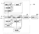
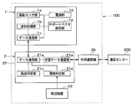
- the tire device 100 is configured to have a tire side device 1 provided on the wheel side and a vehicle body side system 2 including each part provided on the vehicle body side.
- the vehicle body side system 2 includes a receiver 21, a peripheral device 22, an electronic control unit for brake control (hereinafter referred to as a brake ECU) 23, a notification device 24, and the like.
- the part of the tire device 100 that realizes the road surface state determination function corresponds to the road surface state determination device.
- the receiver 21 and the peripheral device 22 of the tire side device 1 and the vehicle body side system 2 constitute a road surface state determining device.
- the tire device 100 of the present embodiment transmits data (hereinafter referred to as road surface data) according to the road surface condition on the traveling road surface of the tire 3 from the tire device 1 and receives the road surface data by the receiver 21 To determine the In addition, the tire device 100 transmits the determination result of the road surface state in the receiver 21 to the notification device 24, and causes the notification device 24 to notify the determination result of the road surface state. This makes it possible to convey the road surface condition to the driver, for example, a dry road, a wet road, or a frozen road, and to warn the driver if the road surface is slippery. In addition, the tire device 100 transmits a road surface state to the brake ECU 23 or the like that performs vehicle motion control so that vehicle motion control for avoiding a danger is performed.
- road surface data data (hereinafter referred to as road surface data) according to the road surface condition on the traveling road surface of the tire 3 from the tire device 1 and receives the road surface data by the receiver 21 To determine the In addition, the tire device 100 transmits the determination result
- the tire side device 1 and the receiver 21 are configured as follows.
- the tire side device 1 is disposed in each of the tires 3 so that bidirectional communication with the vehicle side system 2 is enabled.
- the tire-side device 1 is configured to include a vibration sensor unit 1a, a waveform processing unit 1b, a data communication unit 1c, and a power supply unit 1d, as shown in FIG. , Provided on the back side of the tread 31 of the tire 3.
- the vibration sensor unit 1 a constitutes a vibration detection unit for detecting the vibration applied to the tire 3.
- the vibration sensor unit 1a is configured by an acceleration sensor.
- the vibration sensor unit 1a is an acceleration sensor
- the vibration sensor unit 1a contacts the circular track drawn by the tire-side device 1, that is, the tire shown by arrow X in FIG.
- An acceleration detection signal is output as a detection signal corresponding to the magnitude of the tangential vibration.
- the acceleration acquiring unit 10 generates, as a detection signal, an output voltage in which one of the two directions indicated by the arrow X is positive and the opposite direction is negative.
- the vibration sensor unit 1a performs acceleration detection at a predetermined sampling cycle which is set to a cycle shorter than one rotation of the tire 3, and outputs it as a detection signal.
- vibration sensor part 1a In addition, although the case where the vibration of a tire tangential direction was detected with vibration sensor part 1a was explained here, the same thing can be performed, even if it detects vibration of other directions, for example, tire radial direction.
- the waveform processing unit 1b is configured by a known microcomputer including a CPU, ROM, RAM, I / O, etc., performs signal processing of the detection signal according to a program stored in the ROM or the like, and displays the road surface condition appearing in the detection signal.
- the road surface data to be shown is generated.
- the road surface data includes data including a feature amount of tire vibration and data including a raw waveform of a detection signal in addition to the feature amount.
- the waveform processing unit 1b uses the detection signal output from the vibration sensor unit 1a as a detection signal representing vibration data in the tire tangential direction, and performs waveform processing of the vibration waveform indicated by the detection signal. Extract the feature value of tire vibration.
- the feature amount of the tire G is extracted by performing signal processing on a detection signal of the acceleration of the tire 3 (hereinafter referred to as a tire G).
- the waveform processing unit 1b acquires a raw waveform that is the detection signal of the vibration sensor unit 1a itself, performs signal processing such as noise removal as necessary, and digitizes it (hereinafter, the raw waveform is digitized) Is called raw waveform data). Then, the waveform processing unit 1b transmits the data including the extracted feature amount or the feature amount including raw waveform data to the data communication unit 1c as road surface data.
- the details of the feature quantities referred to here will be described later.
- the waveform processing unit 1b controls data transmission from the data communication unit 1c, and transmits road surface data to the data communication unit 1c at a timing when it is desired to perform data transmission, whereby data from the data communication unit 1c is transmitted. Allow communication to take place.
- the waveform processing unit 1b extracts the feature amount of the tire G each time the tire 3 makes one rotation, and the data communication unit 1c at a rate of once or plural times every one rotation or plural rotations of the tire 3.
- the road surface data is transmitted to
- the waveform processing unit 1b transmits, to the data communication unit 1c, road surface data including the feature amount of the tire G extracted during one rotation of the tire 3 when transmitting the road surface data to the data communication unit 1c. ing.
- the road surface includes raw waveform data in addition to the feature amount of the tire G extracted during one rotation of the tire 3 at that time. Data is transmitted to data communication unit 1c.
- the data communication unit 1 c is a part that constitutes the first transmission / reception unit, and performs data communication with the data communication unit 21 a of the receiver 21 in the vehicle body side system 2 described later.
- the data communication unit 1c is configured to be able to perform two-way communication with the data communication unit 21a.
- the data communication unit 1c is described as one configuration here, but may be configured separately for the transmission unit and the reception unit.
- Various forms of bi-directional communication can be applied.
- Bluetooth communication including BLE (abbreviation of Bluetooth Low Energy) communication, wireless LAN such as wifi (abbreviation of Local Area Network), Sub-GHz communication, ultra wide band Communication, ZigBee, etc. can be applied.
- BLE abbreviation of Bluetooth Low Energy
- wireless LAN such as wifi (abbreviation of Local Area Network)
- Sub-GHz communication ultra wide band Communication
- ZigBee etc.
- Bluetooth is a registered trademark.
- the data communication unit 1c transmits road surface data at that timing.
- the timing of data transmission from the data communication unit 1c is controlled by the waveform processing unit 1b. Then, each time road surface data is sent from the waveform processing unit 1b each time the tire 3 makes one rotation or multiple rotations, or when a request signal from the vehicle body side system 2 is received, the data communication unit 1c Data transmission is to be performed.
- the power supply unit 1 d serves as a power supply of the tire-side device 1 and supplies the power to the respective units provided in the tire-side device 1 so that the respective units can be operated.
- the power supply unit 1 d is configured of, for example, a battery such as a button battery.
- the receiver 21, the peripheral device 22, the brake ECU 23, the notification device 24, and the external communication device 25 constituting the vehicle body side system 2 are driven when a start switch such as an ignition switch (not shown) is turned on.
- the receiver 21 is configured to have a data communication unit 21a, a support vector storage unit 21b, a road surface determination unit 21c, an environment determination unit 21d, and a learning data communication unit 21e. Also, as shown in FIGS. 1 and 2, the receiver 21 can perform data communication with the external communication device 25, and exchanges data with the communication center 200 through the external communication device 25. It is also possible to
- the data communication unit 21a is a part that configures the second transmission / reception unit, and includes road surface data including the feature amount transmitted from the data communication unit 1c of the tire-side device 1 or road surface data including raw waveform data in addition to the feature amount. It plays a role of receiving and communicating to the road surface determination unit 21c.
- the support vector storage unit 21b stores and stores support vectors, and stores, for example, support vectors for each type of road surface.
- the support vector is a feature that serves as an example, and is obtained, for example, by learning using a support vector machine.
- the vehicle equipped with the tire-side device 1 is run experimentally for each type of road surface, and at that time the feature quantity extracted by the feature quantity extraction unit 11a is learned for a predetermined number of tire rotations, and a typical feature quantity among them What is extracted a predetermined number of times is taken as a support vector. For example, feature amounts for one million rotations are learned for each type of road surface, and typical feature amounts for 100 rotations are extracted therefrom as support vectors.
- the support vector storage unit 21b stores the initial support vector at the time of delivery, but also stores the support vector for updating from the learning data communication unit 21e. Therefore, the support vector storage unit 21b updates the support vector.
- the support vector for updating is added to the support vector stored in advance, and the support vector can be used as a new support vector after updating.
- the update of the support vector is not limited to the method of adding the support vector for update to the support vector stored in advance, but at least a part of the support vector stored in advance as the support vector for update It may be a method of rewriting or replacing.
- the road surface determination unit 21c is configured by a known microcomputer including a CPU, a ROM, a RAM, an I / O, and the like, and performs various processes according to a program stored in the ROM or the like to determine the road surface state. Specifically, the road surface determination unit 21c determines the road surface state by comparing the feature amount included in the road surface data transmitted from the waveform processing unit 1b with the support vector stored in the support vector storage unit 21b. ing.
- the feature amount included in the road surface data received this time is compared with the support vector for each type of road surface, and the road surface of the support vector having the closest feature amount is determined as the current traveling road surface.
- the road surface determination unit 21c determines the road surface condition
- the road surface determination unit 21c transmits the determined road surface condition to the notification device 24, and notifies the driver of the road surface condition from the notification device 24 as needed.
- the driver can keep in mind the driving corresponding to the road surface condition, and the danger of the vehicle can be avoided.
- the road surface state determined through the notification device 24 may be always displayed, or the road surface state is determined only when the driving needs to be performed more carefully, such as a wet road or a frozen road. The status may be displayed to warn the driver.
- the road surface state is transmitted from the receiver 21 to the ECU for executing the vehicle movement control such as the brake ECU 23, and the vehicle movement control is performed based on the transmitted road surface state.
- the environment determination unit 21d determines the situation in which the support vector should be learned based on the environment data obtained from the peripheral device 22, and based on the determination result, a request signal for requesting the road surface data to the tire-side device 1 Output For example, the environment determination unit 21d determines whether or not a support vector should be learned. When the environment determining unit 21d determines that the support vector should be learned, the environment determining unit 21d outputs a request signal to the tire-side device 1 through the data communication unit 21a.
- the situation in which the support vector should be learned means that the condition of the road surface of the traveling road surface of the vehicle has changed based on the environmental data, and the condition different from the learning condition in which the support vector is extracted.
- the support vector is a characteristic feature extracted from the learning result under a specific condition, so even if the actual driving condition is different from the driving condition at the time of learning, It is preferable to do learning. For example, in the case of a road surface type different from the stored support vector learning conditions, the support vector should be learned as a new road surface type.
- the road surface type is the same as the stored support vector learning conditions, depending on the actual traveling environment or traveling method of the vehicle, or the change in tire type, air pressure or wear amount, season or The appropriate support vector may change with temperature or weather.
- the detection signal of the vibration sensor unit 1a changes from the expected one, and thus the learned support vector may be in an inappropriate state. .
- Such a case is referred to as "a situation in which support vector should be learned".
- the learning data communication unit 21e acquires road surface data including raw waveform data in addition to the feature amount received by the data communication unit 21a. Then, the learning data communication unit 21e links the data of the type of the situation determined to be the situation where the support vector should be learned by the environment determination unit 21d with the received road surface data, and further, the ID information of the own vehicle. , Etc., and transmits it to the external communication device 25. In this way, the communication center 200 provided outside the vehicle through the external communication unit 25 can distinguish the vehicle from other vehicles in addition to the road surface data including raw waveform data in addition to the feature amount and the data of the type of situation. Data is transmitted.
- the learning data communication unit 21 e acquires the support vector for update sent from the communication center 200 through the external communication device 25, the learning data communication unit 21 e transmits it to the support vector storage unit 21 b.
- the support vector storage unit 21b further adds the support vector obtained as a learning result to the support vector stored so far, and uses it as the new support vector after the update.
- the peripheral device 22 is configured by various devices provided in the vehicle, and as described above, acquires environmental data related to the road surface condition used for recognizing a situation where support vector learning should be performed, such as a change in road surface condition, It plays a role of conveying it to the environment determination unit 21d.
- an on-vehicle camera, a brake ECU 23, a wiper device, a load sensor, a tire pressure monitoring system (hereinafter referred to as TPMS), and the like are applied as the peripheral device 22.
- the environment determination unit 21d analyzes the image data of the on-vehicle camera, and can determine the road surface condition, the actual traveling environment of the vehicle, the traveling method, the weather, and the like based on the analysis result.
- the brake ECU 23 may perform various controls such as ABS (abbreviation of Antilock BrakeSystem) and VSC (abbreviation of Vehicle stability control), and may estimate the road surface friction coefficient or the road surface state.
- the environment determination unit 21d can acquire information on the road surface state from the brake ECU 23, and can determine the road surface state based on the information.
- the environment determination unit 21d acquires information indicating that the wiper drive is being performed from the control unit of the wiper apparatus, and based on it, it can be determined that the road surface state is, for example, a wet state or weather.
- the road surface type is the same as the learning condition of the stored support vector based on the judgment result of the road surface state and the weather, the traveling environment, the traveling method, the weather, etc. are different, or It is possible to identify the type of road surface different from the learning condition. This makes it possible to learn a support vector that takes into consideration various parameters such as the type of road surface, traveling environment, traveling method, and weather.
- a known method may be applied to the estimation of the road surface state based on the analysis of the image data acquired by the on-vehicle camera and the estimation of the road surface state by the brake ECU 23.
- the load applied to the tire 3 can be acquired by the load sensor, and the tire pressure can be acquired by the TPMS. Even if the road surface state is the same as the state in which the support vector is learned, the state quantity may change according to the size of the load applied to the tire 3 and tire information such as the tire pressure. In these cases, even if the road surface type is the same as the stored support vector learning condition, the support vector may not be appropriate. Therefore, by obtaining tire information as environmental data from a load sensor or TPMS, it becomes possible to learn a feature amount taking into consideration tire information as well as the type of road surface.
- the peripheral device 22 may be any device other than the above-described example as long as it can acquire environmental data that can be used to recognize the situation in which the support vector should be learned.
- environmental data For example, weather information, temperature information, season information, area information, road surface freezing information and the like may be acquired by a navigation system (not shown) and the like, and they may be transmitted to the environment determination unit 21d as environment data.
- the type of tire 3 and the wearing condition can also be environmental data as tire information.
- the change in the type of the tire 3 may be registered in the receiver 21 through an operation switch or the like (not shown), and the wear state may be estimated from the travel distance obtained from a meter ECU or the like (not shown) .
- the brake ECU 23 constitutes a braking control device that performs various brake control. Specifically, the brake ECU 23 controls the braking force by increasing or decreasing the wheel cylinder pressure by driving an actuator for controlling the brake fluid pressure. The brake ECU 23 can also control the braking force of each wheel independently. When the road surface condition is transmitted from the receiver 21 by the brake ECU 23, the braking force is controlled as the vehicle motion control based thereon. For example, the brake ECU 23 weakens the braking force generated with respect to the amount of brake operation by the driver, as compared with a dry road surface, when it indicates that the road surface state transmitted is a frozen road. Thereby, it is possible to suppress the wheel slip and to avoid the danger of the vehicle.
- the brake ECU 23 may perform estimation of the road surface friction coefficient and estimation of the road surface state. In that case, the brake ECU 23 transmits information on the road surface state to the environment determination unit 21 d.
- the notification device 24 can also be configured by a buzzer, a voice guidance device, or the like. In that case, the notification device 24 can aurally notify the driver of the road surface condition by buzzer sound or voice guidance.
- the meter display was mentioned as the example as the alerting
- the external communication device 25 is a device for performing data communication with the communication center 200 via a wireless network such as DCM (Data Communication Module).
- the external communication device 25 transmits the road surface data including raw waveform data and data of the type of situation in addition to the feature amount from the receiver 21 and transmits it to the communication center 200 described later. Play.
- the external communication device 25 also plays a role of receiving the updated data of the support vector transmitted from the communication center 200 and transmitting it to the receiver 21.
- each part which comprises the vehicle body side system 2 is connected through in-vehicle LAN (abbreviation of Local AreaNetwork) by CAN (abbreviation of Controller AreaNetwork) communication etc., for example. Therefore, each part can communicate information with each other through the in-vehicle LAN. Furthermore, in the case of the present embodiment, by using the communication center 200 provided outside the vehicle in addition to the tire device 100, a tire system is configured that can further enhance learning data and update support vectors.
- the communication center 200 plays a role as a learning device that realizes a function as a support vector machine that creates a support vector by learning and a function that provides updated data of the created support vector.
- the communication center 200 performs two-way communication with the vehicle body side system 2 using a computer provided outside the vehicle to perform learning calculation of the support vector, and the result of the learning calculation on the vehicle side Play a role in That is, the communication center 200 corresponds to a computer providing a service in cloud computing (hereinafter, referred to as a cloud).
- a cloud a computer providing a service in cloud computing
- the communication center 200 also stores a support vector as initial data before update stored in the support vector storage unit 21b of each vehicle.
- the communication center 200 To the communication center 200, road surface data linked with the type of the situation determined to be the situation where the support vector should be learned from the receiver 21 is delivered through the external communication device 25. Therefore, the communication center 200 reads feature amounts and raw waveform data from road surface data for each type of situation, analyzes them, and performs various operations to learn and calculate support vectors for each type of situation. Then, when the support vector is acquired as a result of the learning operation, the communication center 200 adds it to the support vector stored as initial data and stores it, as well as transmits data to each vehicle side, and the external communication device 25 to the receiver 21. Based on this, the support vector in the support vector storage unit 21b is updated.
- the tire system including the tire device 100 and the communication center 200 according to the present embodiment is configured.
- the feature amount referred to here is an amount indicating the feature of the vibration applied to the tire 3 acquired by the vibration sensor unit 1a, and is expressed as a feature vector, for example.
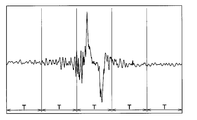
- An output voltage waveform of a detection signal of the vibration sensor unit 1a at the time of tire rotation is, for example, a waveform shown in FIG.
- the output voltage of the vibration sensor unit 1a reaches its maximum value at the start of ground contact when the portion of the tread 31 corresponding to the location of the vibration sensor unit 1a starts to be grounded as the tire 3 rotates.
- the peak value at the start of grounding where the output voltage of the vibration sensor unit 1a has a maximum value is referred to as a first peak value.
- a portion of the tread 31 corresponding to the location where the vibration sensor unit 1 a is disposed is grounded.
- Output voltage has a local minimum value.
- the peak value at the end of grounding where the output voltage of the vibration sensor unit 1a has a local minimum value is referred to as a second peak value.
- the peak value of the output voltage of the vibration sensor unit 1a at the above timing is due to the following reason. That is, when the portion of the tread 31 corresponding to the location where the vibration sensor unit 1a is placed on the ground as the tire 3 rotates, the portion of the tire 3 having a substantially cylindrical surface in the vicinity of the vibration sensor unit 1a It is pressed and deformed into a planar shape. By receiving the impact at this time, the output voltage of the vibration sensor unit 1a takes a first peak value. In addition, when the portion of the tread 31 corresponding to the location where the vibration sensor unit 1a is disposed is separated from the ground contact surface with the rotation of the tire 3, the tire 3 is released from pressure in the vicinity of the vibration sensor unit 1a.
- the output voltage of the vibration sensor unit 1a takes a second peak value. In this way, the output voltage of the vibration sensor unit 1a takes the first and second peak values at the start of grounding and at the end of grounding, respectively. Further, since the direction of the impact when the tire 3 is pressed and the direction of the impact when released from the pressing are opposite, the sign of the output voltage is also the opposite.
- step-in area an instant at which a portion of the tire tread 31 corresponding to the location where the vibration sensor unit 1a is disposed contacts the road surface
- step-out area an instant at which it is separated from the road surface
- step-in area includes the timing at which the first peak value is obtained
- step-out area includes the timing at which the second peak value is obtained.
- the area in front of the stepping area is the area before the stepping area, and the area from the stepping area to the kicking area, that is, the portion of the tire tread 31 corresponding to the location where the vibration sensor portion 1a is in contact.
- "Region after kicking out” is taken as "area after kicking out”.
- five areas R1 to R5 are “pre-step-in area”, “step-in area”, “kick-out front area”, “kick-out area”, and “post-kick out area” in the detection signal in this order. It is shown as.
- the vibration generated in the tire 3 fluctuates in each of the divided areas, and the detection signal of the vibration sensor unit 1a changes, so that the frequency analysis of the detection signal of the vibration sensor unit 1a in each area is performed.
- Detects the road surface condition on the traveling road surface of the vehicle For example, in a slippery road surface condition such as a snowy road, the shear force at the time of kicking is reduced, so the band value selected from the 1 kHz to 4 kHz band becomes smaller in the kicking out region R4 and the after kicking out region R5.
- the band value selected from the 1 kHz to 4 kHz band becomes smaller in the kicking out region R4 and the after kicking out region R5.
- the waveform processing unit 1b detects the detection signal of the vibration sensor unit 1a for one rotation of the tire 3 which has a continuous time axis waveform, as shown in FIG.
- the feature quantity is extracted by dividing into a plurality of sections and performing frequency analysis in each section. Specifically, the power spectrum value in each frequency band, that is, the vibration level in the specific frequency band is determined by performing frequency analysis in each section, and this power spectrum value is used as the feature amount.
- the number of the division divided by the time window of time width T is a value which changes according to the rotational speed of the tire 3 in more detail according to the vehicle speed.
- the number of sections for one tire rotation is n (where n is a natural number).
- the power obtained by passing the detection signal of each section through five band pass filters of a plurality of specific frequency bands for example, 0 to 1 kHz, 1 to 2 kHz, 2 to 3 kHz, 3 to 4 kHz, or 4 to 5 kHz
- This feature quantity is called a feature vector
- a feature vector Xi of a section i (where i is a natural number of 1 ⁇ i ⁇ n) is represented by aik when the power spectrum value of each specific frequency band is indicated by aik It is expressed as in the following equation as a matrix having.
- This determinant X is an expression representing the feature amount for one rotation of the tire.
- the waveform processing unit 1 b extracts the feature quantity represented by the determinant X by frequency analysis of the detection signal of the vibration sensor unit 1 a.
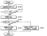
- the waveform processing unit 1 b performs data transmission processing shown in FIG. 6. This process is performed every predetermined control cycle.
- step S100 input processing of the detection signal of the vibration sensor unit 1a is performed. This process is continued in the subsequent step S110 for a period until the tire 3 makes one revolution.
- the process proceeds to the subsequent step S120, and the feature amount of the time axis waveform of the detection signal of the vibration sensor unit 1a for one rotation of the input tire is extracted.
- the fact that the tire 3 has made one rotation is determined based on the time axis waveform of the detection signal of the vibration sensor unit 1a. That is, since the detection signal draws the time axis waveform shown in FIG. 4, one rotation of the tire 3 can be grasped by confirming the first peak value and the second peak value of the detection signal.
- the vibration level of the detection signal of the vibration sensor unit 1a is smaller than the threshold value, it is detected as a period less susceptible to the road surface condition among the "pre-depression region” and the "after kicking region".
- the signal may not be input.
- step S120 The extraction of the feature amount performed in step S120 is performed by the method as described above.
- step S130 it is determined whether the raw waveform measurement mode is in effect.
- the raw waveform measurement mode is a mode in which transmission of the raw waveform of the detection signal of the vibration sensor unit 1a is required in addition to the feature amount as road surface data.
- the request signal is transmitted through the data communication unit 21a.
- the waveform processing unit 1b determines that the raw waveform measurement mode is in effect.
- step S140 If a negative determination is made here, it is not a situation where learning of support vectors is to be performed, so the process proceeds to step S140, and in the case of the current control cycle to execute data transmission for determination of the road surface state which is normally performed.
- the road surface data including the extracted feature amount is transmitted to the data communication unit 1c.
- road surface data including the feature amount is transmitted from the data communication unit 1c.
- step S130 In addition, in the case where an affirmative determination is made in step S130, it is a situation in which support vector learning should be performed. Therefore, the process proceeds to step S150, and road data including raw waveform data is transmitted to data communication unit 1c in addition to the feature value extracted in the current control cycle, in order to execute data transmission for learning support vectors. . Accordingly, road surface data including raw waveform data is transmitted from the data communication unit 1c in addition to the feature amount.
- the road surface condition determination process shown in FIG. 7 the environment determination process shown in FIG. 8, the learning data transmission process shown in FIG. 9, and the learning data update process shown in FIG.
- the road surface condition determination process is performed by the road surface determination unit 21c
- the environment determination process, the learning data transmission process, and the learning data update process are performed by the environment determination unit 21d or the learning data communication unit 21e.
- the respective units provided in 21 may cooperate to execute each process. These processes are executed at each control cycle determined for each process by timer interrupt process or the like.
- the communication center 200 executes a learning process shown in FIG. This process is also executed in the communication center 200 every predetermined control cycle.
- the environment determination process, the learning data transmission process, the learning process, and the learning data update process correspond to each other. Specifically, the learning data transmission process is performed corresponding to the environment determination process, the learning process is performed corresponding to the learning data transmission process, and the learning data update process is performed corresponding to the learning process. Therefore, in the following, after the road surface condition determination processing is described, the environment determination processing, the learning data transmission processing, the learning processing, and the learning data update processing will be described in this order.
- step S200 data reception process is performed in step S200. This process is performed when the data communication unit 21a receives road surface data, and the road surface determination unit 21c takes in the road surface data. When the data communication unit 21a is not performing data reception, the road surface determination unit 21c ends the process without taking in any road surface data.
- step S210 it is determined whether data of road surface data including the feature amount has been received. If received, the process proceeds to step S220. If not received, the process proceeds to step S200. The process of S210 is repeated. Here, it is determined that the road surface data including the feature amount has been received, and it is assumed that even if the road surface data including the raw waveform data is received, it is not received. However, since road surface data including raw waveform data can also be used to determine the road surface condition by extracting data relating to the feature amount, even road surface data including raw waveform data is received As well.
- step S220 determines the road surface state.
- the determination of the road surface state is performed by comparing the feature amount included in the received road surface data with the support vector for each type of road surface stored in the road surface determination unit 21c. For example, the feature amount is determined as the degree of similarity with all the support vectors for each type of road surface, and the road surface of the support vector with the highest degree of similarity is determined as the current road surface.
- calculation of the similarity between the feature amount and all the support vectors for each type of road surface can be performed by the following method.
- the determinant of the feature is X (r)
- the determinant of the support vector is X (s)
- the power spectrum value a ik serving as each element of each determinant Let be represented by a (r) ik , a (s) ik .
- the determinant X (r) of the feature amount and the determinant X (s) of the support vector are expressed as follows.
- the similarity indicates the degree of similarity between the feature quantities indicated by the two determinants and the support vector, which means that the higher the similarity, the more similar.
- the road surface determination unit 21c obtains the similarity using the kernel method, and determines the road surface state based on the similarity.
- the inner product of the determinant X (r) of the feature amount and the determinant X (s) of the support vector in other words, the feature vector Xi of sections divided by each time window of a predetermined time width T in the feature space The distance between the coordinates indicated by is calculated and used as the similarity.
- the time axis waveform at the time of rotation of the tire 3 and the time axis waveform of the support vector each have a predetermined time width T Divide into each section.
- T time width
- n 5 and i is represented by 1 ⁇ i ⁇ 5.
- the feature vector Xi of each section when the tire 3 is rotating this time is Xi (r)
- the feature vector of each section of the support vector is Xi (s).
- feature vectors are obtained by dividing into five specific frequency bands. Therefore, the feature vector Xi of each section is represented in a six-dimensional space aligned with the time axis, and the distance between the coordinates indicated by the feature vectors of the sections is the distance between the coordinates in the six-dimensional space.
- the distance between coordinates indicated by the feature vector of each section is smaller as the feature amount and the support vector are similar and larger as they are not similar, so the smaller the distance is, the higher the similarity is, and the distance is The larger the value, the lower the degree of similarity.
- the distance K yz between coordinates indicated by the feature vector of the compartment between time-division determined for all sections and calculates the distance K yz sum K total of all sections fraction, the sum K total similarity It is used as the corresponding value.
- the total sum K total is compared with a predetermined threshold Th, and it is determined that the degree of similarity is low if the total sum K total is larger than the threshold Th, and the degree of similarity is high if the total K total is smaller than the threshold Th.
- the calculation of the similarity is performed on all the support vectors, and it is determined that the type of the road surface corresponding to the support vector having the highest similarity is the road condition currently being traveled. In this way, road surface condition determination can be performed.
- the sum K total of the distance K yz between two coordinates indicated by the feature vector of each section is used as a value corresponding to the degree of similarity
- another parameter may be used as a parameter indicating the degree of similarity.
- an average distance K ave which is an average value of the distances K yz obtained by dividing the total sum K total by the number of sections can be used.
- various kernel functions can be used to determine the degree of similarity.
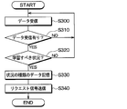
- step S300 data reception processing is performed in step S300. This process is performed by the environment determination unit 21 d receiving environment data from the peripheral device 22. When the environment determination unit 21d is not receiving data, the environment determination unit 21d ends the process without capturing any environment data.
- step S310 determines whether data has been received. If received, the process proceeds to step S320, and if not received, the processes of steps S300 and S310 are repeated until reception.
- step S320 it is determined based on the environmental data whether it is a situation where learning of support vectors is to be performed.
- the affirmative determination is made, and the process proceeds to the processing after step S330, and when not corresponding, the negative determination is repeated and the processing of steps S300 and S310 is repeated.
- step S330 data of the type of situation when it is determined that the “condition for which support vector should be learned” is stored. This data is stored, for example, until it is overwritten by the affirmative determination in step S320 and the process of step S330 being executed. Then, the process proceeds to step S340, instructs the data communication unit 21a to transmit a request signal, and ends the process. Thereby, a request signal is transmitted to each tire side device 1 through the data communication unit 21a.
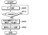
- step S400 data reception processing is performed in step S400.
- This process is performed by the learning data communication unit 21e taking in the road surface data when the data communication unit 21a receives the road surface data.
- the learning data communication unit 21e ends the process without taking in road surface data.
- step S410 it is determined whether data has been received. If it has been received, the process proceeds to step S420. If it has not been received, the processes of steps S400 and S410 are repeated until it is received. Here, it is determined that the road surface data including the raw waveform data is received in addition to the feature amount, and it is assumed that the road surface data not including the raw waveform data is not received.
- step S420 in addition to road surface data when it is determined that the situation should be learned, data of the situation where the environment determination unit 21d should learn the support vector stored in the above-described environment determination process Create data to which vehicle data such as own vehicle ID information is added. Thereafter, the process proceeds to step S430, and the data created in step S420 is transmitted from the learning data communication unit 21e to the communication center 200.
- road surface data including raw waveform data in addition to the feature amount, data of the type of situation, and vehicle data for distinction from other vehicles to the communication center 200 provided outside the vehicle through the external communication device 25. Is transmitted. Then, the road surface data, the type of situation data, and the vehicle data are stored in the communication center 200.
- step S500 data reception processing is performed in step S500.
- a process of receiving the data transmitted in step S430 of FIG. 9 is performed.
- the process proceeds to step S510, and based on the data received in step S500, the feature amount and raw waveform data are read from the road surface data for each type of situation for each vehicle, and they are analyzed and various calculations are performed. Learn and operate support vectors by type.
- step S520 it is determined whether there is a need for data update based on the learning calculation result. For example, when the amount of data collected for a learning operation is small and a support vector is not obtained, or when the result of the learning operation has not changed from the currently stored support vector, the need for data update is required. It is determined that there is no sex. Then, as in the case where a support vector is obtained and a support vector different from the currently stored support vector is obtained, when an affirmative determination is made in step S520, the process proceeds to step S530. As a result, data transmission of the support vector linked to the type of the situation is performed together with the vehicle data for determining the own data to the vehicle side.
- the communication center 200 also stores the road surface state indicated by the vehicle data, the support vector linked to the type of the situation, and the road surface data. As a result, it is possible to accumulate learning data of support vectors for each vehicle data, that is, for each vehicle, data of the road surface condition of the traveling road surface of the vehicle, and the like, and it becomes possible to effectively utilize the accumulated data. If the negative determination is made in step S520, the process ends.
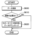
- step S600 data reception processing is performed in step S600.
- a process of receiving the data transmitted in step S530 of FIG. 10 is performed. Thereafter, the process proceeds to step S610, and based on the data received in step S600, it is determined whether it is necessary to update the support vector currently stored in the support vector storage unit 21b. If the received data includes a support vector different from the support vector currently stored in the support vector storage unit 21b, it is determined that the data needs to be updated, and the process proceeds to step S620.
- step 620 by transmitting data to the support vector storage unit 21b, the data stored in the support vector storage unit 21b is updated, and the process ends.
- the data is updated when a negative determination is made in step S610. End the process.
- the present embodiment is such that the support vector is stored in the tire side device 1 in the first embodiment, and the other parts are the same as the first embodiment, and therefore, parts different from the first embodiment. Will be explained only.
- the tire side device 1 is provided with the support vector storage unit 1 e, and the tire side device 1 can determine the road surface state.
- the data of the support vector stored in advance in the support vector storage unit 1 e is the same as the support vector storage unit 21 b described in the first embodiment.
- the road surface state may be determined based on the feature amount extracted from the detection signal of the vibration sensor unit 1a and the storage data of the support vector storage unit 1e. it can. Then, data indicating the determination result of the road surface condition is transmitted from the data communication unit 1c to the receiver 21, and the road surface determination unit 21c determines the road surface condition based on the determination result indicated by the data transmitted from the tire device 1. It is notified to the notification device 24.
- road surface data including raw waveform data is transmitted from the tire side device 1 in addition to the feature amount. It is transmitted to the communication center 200 through the communication device 25.
- the communication center 200 is used as the cloud providing source computer to perform a learning operation of the support vector, and the result of the learning operation is transmitted to the receiver 21 through the external communication device 25.
- the data of the support vector to be updated is the tire side device from the data communication unit 21a. It is transmitted to 1. Then, in addition to the support vector stored in the support vector storage unit 1e, data of a new support vector is stored.
- the tire side device 1 basically, the tire side device 1, the receiver 21, and the communication center 200 perform the same processes as in the first embodiment except that the above-described operation is performed, that is, The same processing as in FIGS. 6 to 11 is performed.
- step S120 in FIG. 6 the road surface state is also determined in addition to the extraction of the feature amount, and in step S140, the road surface data including the feature amount may also be sent. I am sending data.
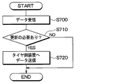
- processing shown in FIG. 14 is performed instead of the processing shown in FIG. Specifically, in steps S700 to S710 shown in FIG. 14, processing similar to steps S600 to S610 shown in FIG. 11 is performed, and then in step S720, transmission of support vector data to be updated to the tire side device 1 is performed. Do.
- step S710 it is determined whether the support vector currently stored in the support vector storage unit 1e needs to be updated. With regard to this, it is necessary to include data representing that the content to be updated is included in the data transmitted from the communication center 200, and to update the data in the receiver 21 when the data is included. It may be determined to be present.
- Third Embodiment A third embodiment will be described.
- the present embodiment effectively utilizes the data stored in the communication center 200 as described in the first embodiment, and the storage of data in the communication center 200 is the same as in the first and second embodiments. Because of this, only differences from the first and second embodiments will be described.
- a support vector serving as learning data is accumulated in the communication center 200. Therefore, in the case of a vehicle of the same vehicle type or a vehicle having the same tire, there is a possibility that various data stored in the communication center 200 can be diverted. For this reason, when various data transmitted from the vehicle and the calculated support vector are stored in the communication center 200, the data can be diverted to other vehicles. Specifically, another vehicle performs the processing shown in FIGS. 15 and 16 to divert data.
- the tire side device 1 and the vehicle body side system 2 as shown in FIG. 2 are also provided for other vehicles. Therefore, in the tire side device 1, the process shown in FIG. 6 is performed, and in the vehicle body side system 2, the processes shown in FIGS. 7 to 9 and 11 are performed.
- the communication center 200 executes the process shown in FIG. In addition to that, the vehicle body side system 2 executes the download request process shown in FIG. 15, and the communication center 200 executes the data download process shown in FIG.
- step S800 the vehicle body side system 2 performs data reception processing in step S800.
- This process is the same process as step S200 in FIG.
- step S810 it is determined whether the data is different from the learned data. For example, the similarity between the feature amount included in the received data and all the support vectors stored in the support vector storage unit 21b is calculated. Then, if there is only one having a low degree of similarity, it is considered that the support vector that has already been learned is not included as a road surface state of the road surface currently being traveled in accordance with the type of the road surface. It is judged that it is different from the data. Also, if the environmental data obtained from the peripheral device 22 instead of the data received from the tire-side device 1 in step S800 indicates a condition different from the learning condition from which the learned support vector has been extracted, You may judge that it is different.
- step S810 if a negative determination is made in step S810, the process ends as it is, and if a positive determination is made, the process proceeds to step S820.
- step S820 a request signal of learning data is transmitted to the communication center 200, which is a cloud providing source computer, together with vehicle data for distinguishing it from other vehicles.
- vehicle data as in the above, it is sufficient if the data can be used to distinguish between the host vehicle and other vehicles, but here, by including more detailed data such as the type of the tire 3, the situation of the host vehicle can be further improved. It is possible to request corresponding learning data.
- data of the type of situation is also transmitted, it becomes possible to request learning data according to the type of situation. Thereafter, learning data is sent from the communication center 200 based on the processing shown in FIG. 16 described later, so that the learning data is downloaded in step S830.
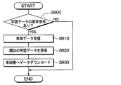
- step S900 it is determined whether a request signal for learning data from the vehicle side has been received. If a negative determination is made here, the process ends as it is, and if a positive determination is made, the process proceeds to step S 910. If a request signal for learning data is transmitted in step S820 described above, an affirmative determination is made in this step.
- step S910 a process of receiving vehicle data sent together with a request signal for learning data is performed. Then, the process proceeds to step S920, and learning data similar to the vehicle data is searched. Among the data stored in the communication center 200, for example, learning data of a vehicle of the same vehicle type, a vehicle of the same tire, or a vehicle corresponding to both of them is searched as similar learning data. Thereafter, the process proceeds to step S 930, and transmission of learning data of various data and support vectors stored in the communication center 200 is performed to cause the vehicle that has transmitted the request signal of learning data to download the learning data. Do. Also at this time, vehicle data is sent along with the learning data, so that a vehicle to be downloaded can be specified.
- the communication center 200 since the communication center 200 also stores data on the road surface condition of the traveling surface of the preceding vehicle, etc., if the data is also transmitted to other vehicles, the other vehicles are traveling on their own. It becomes possible to know in advance the data of the road surface condition even for the non-road surface. In that case, in another vehicle, it is not necessary to acquire data for determining the road surface state.
- the tire-side device 1 since the tire-side device 1 is provided with the support vector storage unit 1e, it may be determined in the tire-side device 1 whether or not it is different from the learned data. . Then, if different from the learned data, the request signal may be transmitted from the tire device 1 to the vehicle body system 2.
- the vehicle body side system 2 when it becomes a condition different from the learning condition in which the support vector is extracted, it is preferable to obtain learning data under that condition as "a situation where learning of the support vector should be performed". .
- a specific example of the “condition in which support vector should be learned” will be described.
- the vehicle body side system 2 when it is determined by the vehicle body side system 2 that “the support vector should be learned” based on the environment data of the peripheral device 22, the vehicle body side system 2 sends a response to the tire device 1.
- an instruction to transmit road surface data such as raw waveform data is issued.
- this is merely an example, and the method described in the first embodiment may be used.
- road surface data such as raw waveform data
- the vehicle body side system 2 determines that "the situation where support vector should be learned"
- the road surface data already received is received. It may be in the form of communication to the communication center 200.
- the environment determination unit 21d and the like execute the processes shown in FIGS. 17 to 24. These processes are performed by dividing the environment determination process shown in FIG. 8 described in the first embodiment into the contents to be determined, and are executed here as an independent flow, for example, as a timer interrupt process. However, it may be a single flow.
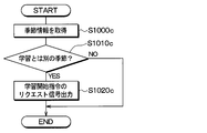
- step S1000 a acquisition processing of temperature information of the outside air temperature is performed. This process is performed, for example, by using the navigation system as the peripheral device 22 to acquire temperature information. Then, the process proceeds to step S1010a, and it is determined whether the outside air temperature acquired earlier is 0 ° C. or less. That is, if the environment in which the support vector has been learned is, for example, an environmental temperature of about 25 ° C., and if the environment is such that a temperature difference from the environmental temperature occurs, the outside air temperature is 0 ° C. or less In this case, it is considered as "a situation in which support vector should be learned". If an affirmative determination is made here, the process proceeds to step S1020a, a request signal of a learning start instruction is output to the tire device 1 or the communication center 200 side, and the process is ended.
- step S1000 b weather information acquisition processing is performed. This process is also performed, for example, by using the navigation system as the peripheral device 22 and acquiring weather information. Then, the process proceeds to step S1010b, and it is determined whether the weather acquired earlier is the weather without learning experience, for example, heavy rain, strong wind, or the like. That is, the environment where the amount of rainfall and the wind speed were higher than the situation where the amount of rainfall and the wind speed were learned was the situation where the amount of rainfall per unit time was less than the predetermined amount and the wind speed was less than the predetermined value. In this case, it is considered as "the situation where support vector should be learned".
- step S1020b executes the same process as step S1020a described above, and ends the process.
- heavy rain and strong wind are mentioned as an example as an example of weather information here, of course, it is applicable also to other information.
- step S1000 c seasonal information acquisition processing is performed in step S1000 c.
- This process is also performed, for example, by using the navigation system as the peripheral device 22 and acquiring current seasonal information or acquiring current date and time information.
- the process proceeds to step S1010c, and it is determined whether the current season acquired earlier is a season different from the learned season. That is, in the case where the support vector has been learned, for example, in the spring season, when the current season is in an environment such as winter, it is regarded as the “condition in which support vector should be learned”. If an affirmative determination is made here, the process proceeds to step S1020c, performs the same process as step S1020a described above, and ends the process.
- step S1000 d tire information acquisition processing is performed in step S1000 d.
- This process is performed by reading the content registered in the receiver 21 when the type of the tire 3 is changed, for example, by using the receiver 21 as the peripheral device 22. Then, the process proceeds to step S1010d, and it is determined whether the type of the tire 3 indicated by the previously acquired tire information is a different type from that learned, for example, whether there is a change from a genuine tire. That is, in the situation where the support vector is learned, for example, when the tire is a genuine tire, when the type of the current tire 3 is not a genuine tire, it is considered as "a situation where learning of the support vector should be performed".
- step S1020d the same process as step S1020a described above is performed, and the process is ended.
- the tire information can also be newly added as learned tire information.
- newly learned tire information may be included in the type of the tire 3 at the time of learning.
- step S1000 e a tire air pressure acquisition process is performed. This process is performed by using the TPMS as the peripheral device 22 and acquiring tire pressure information as tire information from the TPMS, for example. Then, the process proceeds to step S1010e, and it is determined whether the previously-obtained tire pressure is less than or equal to a predetermined threshold value. That is, in the situation in which the support vector has been learned, for example, when the tire pressure is appropriate, if the current tire pressure has dropped to a threshold value or less, it is determined that "the situation in which support vector should be learned". If an affirmative determination is made here, the process proceeds to step S1020e, the same process as step S1020a described above is performed, and the process is ended.
- step S1000 f road surface state acquisition processing is performed in step S1000 f.
- This processing is performed, for example, by using the on-vehicle camera or the brake ECU 23 as the peripheral device 22 to acquire an estimation result of the road surface condition based on analysis of image data acquired by the on-vehicle camera or acquiring an estimation result of the road surface condition by the brake ECU 23 To be done.
- the process proceeds to step S1010f, and it is determined whether the road surface state acquired earlier is a non-learned road surface with no learning experience. That is, since the situation in which the support vector has been learned is, for example, a learning road surface such as a dry road surface such as asphalt road, a wet road surface, a frozen road, a snow road etc. " If an affirmative determination is made here, the process proceeds to step S1020f, the same process as step S1020a described above is performed, and the process is ended.
- step S1000 g detection processing of remaining grooves of the tire 3 corresponding to the tire worn state is performed.
- the receiver 21 and the meter ECU are registered as peripheral devices 22 and the fact that tire replacement has been performed is registered in the receiver 21 and the travel distance from the time of registration is acquired from the meter ECU. It is performed by calculating the remaining groove of.
- the process proceeds to step S1010g, and it is determined whether the remaining groove of the tire 3 acquired earlier is equal to or less than the threshold. That is, since the remaining grooves of the tire 3 are sufficiently present in the situation in which the support vector is learned, when the remaining grooves are equal to or less than the threshold value, the “condition in which the support vector should be learned” is set. If an affirmative determination is made here, the process proceeds to step S1020g, the same process as step S1020a described above is performed, and the process is ended.
- acceleration / deceleration information acquisition processing is performed in step S1000 h.
- This process is performed, for example, by using the brake ECU 23 and the meter ECU as the peripheral device 22 and calculating the acceleration / deceleration from the vehicle speed handled by them.
- the process proceeds to step S1010h, and it is determined whether the acceleration / deceleration acquired earlier is outside the predetermined threshold range. That is, since the acceleration / deceleration is within the predetermined threshold range in the situation where the support vector is learned, when the acceleration / deceleration is outside the threshold range, it is considered as "the situation where the support vector should be learned". If an affirmative determination is made here, the process proceeds to step S1020h, executes the same processing as step S1020a described above, and ends the processing.
- the environment determination process is performed, and when the request signal of the learning start instruction is output in steps S1020a to S1020h, the tire device 1, the vehicle body system 2 and the communication center 200 perform various processes based thereon. Run.
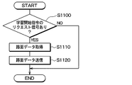
- step S1100 it is determined whether or not there is a request signal for learning start instruction. As described above, when the request signal of the learning start instruction is output from the vehicle body side system 2, an affirmative determination is made in this step, and the process proceeds to step S1110. Then, after road surface data including raw waveform data for one rotation of the tire is acquired, the process proceeds to step S1120, and the road surface data is transmitted to the vehicle body side system 2 as data.
- the process of step S1110 can be performed by the same method as each process of FIG. 6 described above.
- step S1200 reception processing of road surface data including raw waveform data transmitted from the tire-side device 1 is performed, and then, in step S1210, it is determined whether road surface data is acquired.
- step S1210 it is determined whether road surface data is acquired.
- the process ends. If it can be received, the process advances to step S 1220 to execute processing of transmitting the received road surface data as learning data to the communication center 200 in order to upload it to the communication center 200.
- step S1300 it is determined whether there is a request signal for learning start instruction. As described above, when the request signal of the learning start instruction is output from the vehicle body side system 2, an affirmative determination is made in this step, and the process proceeds to step S1310. Then, it is determined whether or not road surface data including raw waveform data transmitted from the vehicle body side system 2 is acquired, and if acquired, the process proceeds to step S 1320 to start learning and when learning is completed, the result is used as the vehicle body side system Transfer to 2 and download to the support vector storage unit 21b.
- the processing method of the communication center 200 at this time is the same as steps S510 to S530 in FIG. 10, and based on that, the method in which the vehicle body side system 2 downloads data to the support vector storage unit 21b is also the step S600 to FIG. Similar to S620.
- This embodiment detects a change in the road surface condition in the tire side device 1 in the first to fourth embodiments, and when there is a change in the road surface condition, transmits the road surface change to the vehicle body side system 2 To start learning.
- the other aspects of the present embodiment are the same as those of the first to fourth embodiments, and therefore, only different parts from the first to fourth embodiments will be described.
- the tire side device 1 detects a change in the road surface state based on the detection signal of the vibration sensor unit 1a, and transmits the change to the vehicle body side system 2. Specifically, the tire side device 1 executes a road surface change detection process shown in FIG.
- step S1400 input processing of the detection signal of the vibration sensor unit 1a is performed, and in step S1410, a period until the tire 3 makes one rotation is continued.
- the process proceeds to step S1420, and the feature amount of the time axis waveform of the detection signal of the acceleration acquisition unit 10 for one rotation of the input tire is extracted as the current feature amount. Do.
- the feature quantity extraction method at this time is the same as step S120 in FIG.
- step S1430 the similarity is determined for the current feature amount and the previous feature amount by the method described in step S220 of FIG. It is determined whether or not there is.
- step S1440 the fact that there is a change in the road surface condition is stored in step S1440.
- step S1450 the current feature amount is stored as the previous feature amount in the feature amount storage unit 11b, and the process is ended.
- step S1500 it is determined whether it has been determined that there has been a change in the road surface state. This determination is performed based on whether or not there is a change in the road surface state stored in step S1440 of FIG. 27 described above. If an affirmative determination is made here, the process proceeds to step S1510, and data indicating that the road surface state has changed is transmitted to the vehicle body side system 2 together with the road surface data including the feature amount and raw waveform data this time. Then, if a negative determination is made here, the process proceeds to step S1520, and road surface data including the feature amount this time is transmitted.
- each process shown in FIGS. 7 to 11 described in the first embodiment is executed.
- Each of these processes is substantially the same as in the first embodiment, but at step S320 in FIG. 8, data indicating that there is a change in the road surface condition has been transmitted from the tire-side device 1. It is determined that "the situation where learning of the vector should be performed".
- the tire side device 1 detects a change in the road surface state, and transmits it to the vehicle body side system 2 as "a situation where learning of support vector should be performed", and causes the communication center 200 to learn the support vector. It can also be done.
- the vibration sensor unit 1a constituting the vibration detection unit is constituted by an acceleration sensor
- other elements capable of detecting vibration for example, piezoelectric elements etc. It can also be done.
- the road surface data including the feature amount and the raw waveform data is sent to the communication center 200, only one of the feature amount and the raw waveform data may be sent. Further, integral value data of vibration waveforms of the five regions R1 to R5 included in vibration data during one rotation of the tire 3 may be sent to the communication center 200 as road surface data.
- another ECU such as the brake ECU 23 or the like determines the degree of similarity, determines the road surface state, or determines an instruction signal state at any place of the vehicle body side system 2. Transmission may be performed.
- the communication center 200 is used for the support vector learning operation. This is because, for example, the amount of data at the time of performing the learning operation is enormous, and for example, the receiver 21 is provided with a function of performing the learning operation of the support vector so that each vehicle can carry out the learning operation. It is good.
- the communication center 200 it is also possible to perform the learning calculation of the support vector in consideration of various information which can not be obtained by each vehicle, for example, a road surface condition determined based on data of other vehicles. Therefore, by using the communication center 200, it is possible to perform learning calculation of the support vector used for updating more accurately.
- the bidirectional communication is performed between the tire device 1 and the receiver 21 in each of the above embodiments, the bidirectional communication may not necessarily be performed.
- the receiver 21 is configured to include the support vector storage unit 21b, when the support vector is to be updated based on the environmental data of the peripheral device 22, the support is supported based on the road surface data from the tire device 1.
- Perform vector learning operation The learning calculation of the support vector may be performed by the communication center 200 or may be performed by the receiver 21 or the like by providing the receiver 21 with a function to perform the learning calculation. As described above, it is possible to perform the learning calculation and update of the support vector even as one-way communication in which data communication can be performed only from the tire-side device 1 to the receiver 21.
- a support vector is taken as an example as teacher data, but teacher data is updated by other known machine learning.
- the present disclosure is also applicable to
- tire side apparatus 1 was provided with respect to each of the some tire 3 in said each embodiment, what is necessary is just to be provided in at least one.
Landscapes
- Engineering & Computer Science (AREA)
- Mechanical Engineering (AREA)
- Environmental & Geological Engineering (AREA)
- Mathematical Physics (AREA)
- Transportation (AREA)
- Physics & Mathematics (AREA)
- Automation & Control Theory (AREA)
- Life Sciences & Earth Sciences (AREA)
- Atmospheric Sciences (AREA)
- Biodiversity & Conservation Biology (AREA)
- Ecology (AREA)
- Environmental Sciences (AREA)
- Tires In General (AREA)
- Control Of Driving Devices And Active Controlling Of Vehicle (AREA)
Abstract
車体側システム(2)車両に備えられる周辺装置(22)にて環境データを取得し、この環境データに基づいてサポートベクタの学習を行うべき状況であることを判定する。そして、教師データの学習を行うべき状況である場合には、状況の種類と紐付けした路面データを用いて教師データの学習演算を行わせている。これにより、保存部(21b)に、初期データとして保存している教師データ以外にも、状況に合わせて教師データを更新していくことができる。
Description
本出願は、2017年10月30日に出願された日本特許出願番号2017-209402号と、2018年6月14日に出願された日本特許出願番号2018-113705号とに基づくもので、ここにその記載内容が参照により組み入れられる。
本開示は、タイヤが受ける振動を検出し、振動データに基づいて路面状態を示す路面データを作成するタイヤ側装置と、路面データを受信して路面状態を推定する車体側システムとを有する路面状態判別装置およびそれを備えたタイヤシステムに関するものである。
従来、特許文献1において、タイヤトレッドの裏面に加速度センサを備え、加速度センサにてタイヤに加えられる振動を検出すると共に、その振動の検出結果に基づいて路面状態の推定を行う路面状態判別方法が提案されている。この路面状態判別方法では、加速度センサが検出したタイヤの振動波形から特徴ベクトルを抽出し、抽出した特徴ベクトルと路面の種類ごとに記憶しておいた全サポートベクタとの類似度を計算することで、路面状態を判別する。
従来では、路面状態判別のアルゴリズムがオフライン、つまり事前学習型のものであり、例えばサポートベクタマシンを用いた学習によってサポートベクタを取得し、その保存データを路面状態の判別に用いている。しかしながら、全く未知の路面を走行した場合などのように、事前に学習した状況と異なる状況では、事前学習したサポートベクタの保存データのみでは適切な路面状態の判別が行えなくなる可能性がある。
本開示は、事前学習した保存データのみでは対応できない状況においても、適切に路面状態の判別が行えるようにできる路面状態判別装置およびそれを有するタイヤシステムを提供することを目的とする。
本開示の1つの観点における路面状態判別装置は、タイヤ側装置と車体側システムとを有し、タイヤ側装置は、タイヤの振動の大きさに応じた検出信号を出力する振動検出部と、検出信号の波形に現れる路面状態を示す路面データを生成する波形処理部と、路面データを送信する第1データ通信部と、を備え、車体側システムは、第1データ通信部から送信された路面データを受信する第2データ通信部と、教師データを保存する保存部と、路面データと教師データとに基づいて車両の走行路面における路面状態を判別する路面判定部と、路面状態に関わる環境データを取得する周辺装置と、環境データに基づいて教師データの学習演算を行うべき状況であるか否かの判定を行うと共に、教師データの学習演算を行うべき状況であるとの判定結果に基づいて、第2データ通信部を通じてタイヤ側装置にリクエスト信号を出力させる環境判定部と、を備えている。そして、タイヤ側装置は、第1データ通信部にてリクエスト信号を受信すると、波形処理部にて路面データを生成すると共に、第1データ通信部を通じて路面データを車体側システムに送信し、車体側システムは、タイヤ側装置から伝えられた路面データと環境データが示す状況の種類とを用いた機械学習により教師データの更新データが学習演算されると、保存部に記憶された教師データに更新データを加味したデータを新たな教師データとして保存する。
このように構成される路面状態判別装置では、車両に備えられる周辺装置にて環境データを取得し、この環境データに基づいて教師データの学習を行うべき状況であることを判定している。そして、教師データの学習を行うべき状況である場合には、状況の種類と紐付けした路面データを用いて教師データの学習演算を行わせている。これにより、保存部に、初期データとして保存している教師データ以外にも、状況に合わせて教師データを更新していくことができる。
したがって、事前学習した保存データのみでは対応できない状況においても、適切に路面状態の判別が行えるようにできる路面状態判別装置とすることが可能となる。
なお、各構成要素等に付された括弧付きの参照符号は、その構成要素等と後述する実施形態に記載の具体的な構成要素等との対応関係の一例を示すものである。
なお、各構成要素等に付された括弧付きの参照符号は、その構成要素等と後述する実施形態に記載の具体的な構成要素等との対応関係の一例を示すものである。
以下、本開示の実施形態について図に基づいて説明する。なお、以下の各実施形態相互において、互いに同一もしくは均等である部分には、同一符号を付して説明を行う。
(第1実施形態)
図1~図12を参照して、本実施形態にかかる路面状態判別機能を有するタイヤ装置100について説明する。本実施形態にかかるタイヤ装置100は、車両の各車輪に備えられるタイヤの接地面に加わる振動に基づいて走行中の路面状態を判別すると共に、路面状態に基づいて車両の危険性の報知や車両運動制御などを行うものである。
図1~図12を参照して、本実施形態にかかる路面状態判別機能を有するタイヤ装置100について説明する。本実施形態にかかるタイヤ装置100は、車両の各車輪に備えられるタイヤの接地面に加わる振動に基づいて走行中の路面状態を判別すると共に、路面状態に基づいて車両の危険性の報知や車両運動制御などを行うものである。
図1および図2に示すようにタイヤ装置100は、車輪側に設けられたタイヤ側装置1と、車体側に備えられた各部を含む車体側システム2とを有する構成とされている。車体側システム2としては、受信機21、周辺装置22、ブレーキ制御用の電子制御装置(以下、ブレーキECUという)23、報知装置24などが備えられている。なお、このタイヤ装置100のうち路面状態判別機能を実現する部分が路面状態判別装置に相当する。本実施形態の場合、タイヤ側装置1と車体側システム2のうちの受信機21や周辺装置22が路面状態判別装置を構成している。
本実施形態のタイヤ装置100は、タイヤ側装置1よりタイヤ3の走行路面における路面状態に応じたデータ(以下、路面データという)を送信すると共に、受信機21で路面データを受信して路面状態の判別を行う。また、タイヤ装置100は、受信機21での路面状態の判別結果を報知装置24に伝え、報知装置24より路面状態の判別結果を報知させる。これにより、例えばドライ路やウェット路もしくは凍結路であることなど、路面状態をドライバに伝えることが可能となり、滑り易い路面である場合にはドライバに警告することも可能となる。また、タイヤ装置100は、車両運動制御を行うブレーキECU23などに路面状態を伝えることで、危険を回避するための車両運動制御が行われるようにする。例えば、凍結時には、ドライ路の場合と比較してブレーキ操作量に対して発生させられる制動力が弱められるようにすることで、路面μが低いときに対応した車両運動制御となるようにする。具体的には、タイヤ側装置1および受信機21は、以下のように構成されている。
タイヤ側装置1は、各タイヤ3それぞれに配置され、車体側システム2との間において双方向通信が可能とされている。具体的には、タイヤ側装置1は、図2に示すように、振動センサ部1a、波形処理部1b、データ通信部1c、電源部1dを備えた構成とされ、図3に示されるように、タイヤ3のトレッド31の裏面側に設けられる。
振動センサ部1aは、タイヤ3に加わる振動を検出するための振動検出部を構成するものである。例えば、振動センサ部1aは、加速度センサによって構成される。振動センサ部1aが加速度センサとされる場合、振動センサ部1aは、例えばタイヤ3が回転する際にタイヤ側装置1が描く円軌道に対して接する方向、つまり図3中の矢印Xで示すタイヤ接線方向の振動の大きさに応じた検出信号として、加速度の検出信号を出力する。より詳しくは、加速度取得部10は、矢印Xで示す二方向のうちの一方向を正、反対方向を負とする出力電圧を検出信号として発生させる。例えば、振動センサ部1aは、タイヤ3が1回転するよりも短い周期に設定される所定のサンプリング周期ごとに加速度検出を行い、それを検出信号として出力している。
なお、ここでは振動センサ部1aにて、タイヤ接線方向の振動を検出する場合について説明したが、他の方向、例えばタイヤ径方向の振動を検出しても同様のことを行える。
波形処理部1bは、CPU、ROM、RAM、I/Oなどを備えた周知のマイクロコンピュータによって構成され、ROMなどに記憶されたプログラムに従って検出信号の信号処理を行い、検出信号に現れる路面状態を示す路面データを生成する。路面データとしては、タイヤ振動の特徴量を含むデータと、特徴量に加えて検出信号の生波形を含むデータとがある。
具体的には、波形処理部1bは、振動センサ部1aが出力する検出信号をタイヤ接線方向の振動データを表す検出信号として用いて、この検出信号が示す振動波形の波形処理を行うことで、タイヤ振動の特徴量を抽出する。本実施形態の場合、タイヤ3の加速度(以下、タイヤGという)の検出信号を信号処理することで、タイヤGの特徴量を抽出する。また、波形処理部1bは、振動センサ部1aの検出信号そのものとなる生波形を取得し、必要に応じてノイズ除去等の信号処理を行い、それをデータ化する(以下、生波形をデータ化したものを生波形データという)。そして、波形処理部1bは、抽出した特徴量を含むデータもしくは特徴量に加えて生波形データを含めたものを路面データとしてデータ通信部1cに伝える。なお、ここでいう特徴量の詳細については後で説明する。
また、波形処理部1bは、データ通信部1cからのデータ送信を制御しており、データ送信を行わせたいタイミングでデータ通信部1cに対して路面データを伝えることで、データ通信部1cからデータ通信が行われるようにする。例えば、波形処理部1bは、タイヤ3が1回転するごとにタイヤGの特徴量の抽出を行い、タイヤ3の1回転もしくは複数回転する毎に1回もしくは複数回の割合で、データ通信部1cに対して路面データを伝えている。例えば、波形処理部1bは、データ通信部1cに対して路面データを伝えるときのタイヤ3の1回転中に抽出されたタイヤGの特徴量を含んだ路面データをデータ通信部1cに対して伝えている。また、波形処理部1bは、車体側システム2からリクエスト信号を受け取ったときにも、そのときのタイヤ3の1回転中に抽出されたタイヤGの特徴量に加えて生波形データを含めた路面データをデータ通信部1cに対して伝える。
データ通信部1cは、第1送受信部を構成する部分であり、車体側システム2における受信機21の後述するデータ通信部21aとの間においてデータ通信を行う。データ通信部1cは、データ通信部21aとの間において双方通信を行える構成とされている。データ通信部1cは、ここでは1つの構成として記載されているが、送信部と受信部それぞれ別々に構成されたものであっても良い。双方向通信の形態については様々なものを適用することができ、BLE(Bluetooth LowEnergyの略)通信を含むブルートゥース通信、wifiなどの無線LAN(Local AreaNetworkの略)、Sub-GHz通信、ウルトラワイドバンド通信、ZigBeeなどを適用できる。なお、「ブルートゥース」は登録商標である。
例えば、データ通信部1cは、波形処理部1bから路面データが伝えられると、そのタイミングで路面データの送信を行う。データ通信部1cからのデータ送信のタイミングについては、波形処理部1bによって制御されている。そして、波形処理部1bからタイヤ3が1回転もしくは複数回転するごとに路面データが送られてくるたびに、もしくは、車体側システム2からのリクエスト信号を受信したときに、データ通信部1cからのデータ送信が行われるようになっている。
電源部1dは、タイヤ側装置1の電源となるものであり、タイヤ側装置1に備えられる各部への電力供給を行うことで、各部が作動させられるようにしている。電源部1dは、例えばボタン電池等の電池で構成される。
一方、車体側システム2を構成する受信機21、周辺装置22、ブレーキECU23、報知装置24および外部通信機25は、図示しないイグニッションスイッチなどの起動スイッチがオンされると駆動されるものである。
受信機21は、図2に示すように、データ通信部21a、サポートベクタ保存部21b、路面判定部21c、環境判定部21dおよび学習データ通信部21eを有した構成とされている。また、図1および図2に示すように、受信機21は、外部通信機25との間においてデータ通信を行えるようになっており、外部通信機25を通じて通信センター200との間においてデータの授受を行うことも可能となっている。
データ通信部21aは、第2送受信部を構成する部分であり、タイヤ側装置1のデータ通信部1cより送信された特徴量を含む路面データもしくは特徴量に加え生波形データを含めた路面データを受信し、路面判定部21cに伝える役割を果たす。
サポートベクタ保存部21bは、サポートベクタを記憶して保存するものであり、例えば路面の種類ごとにサポートベクタを保存している。サポートベクタは、手本となる特徴量のことであり、例えばサポートベクタマシンを用いた学習によって得ている。タイヤ側装置1を備えた車両を実験的に路面の種類別に走行させ、そのときに特徴量抽出部11aで抽出した特徴量を所定のタイヤ回転数分学習し、その中から典型的な特徴量を所定数分抽出したものがサポートベクタとされる。例えば、路面の種類別に、100万回転分の特徴量を学習し、その中から100回転分の典型的な特徴量を抽出したものをサポートベクタとしている。
また、サポートベクタ保存部21bは、納車時に予め初期時のサポートベクタを保存しているが、学習データ通信部21eから更新用のサポートベクタが伝えられると、それも保存する。このため、サポートベクタ保存部21bは、サポートベクタの更新を行う。ここでは、予め保存してあったサポートベクタに対して更新用のサポートベクタを加え、それを更新後の新たなサポートベクタとして利用できるようにしている。なお、サポートベクタの更新は、予め保存してあったサポートベクタに対して更新用のサポートベクタを加える手法に限らず、予め保存してあったサポートベクタの少なくとも一部を更新用のサポートベクタに書き換えたり、置き換えたりする手法であっても良い。
路面判定部21cは、CPU、ROM、RAM、I/Oなどを備えた周知のマイクロコンピュータによって構成され、ROMなどに記憶されたプログラムに従って各種処理を行って、路面状態を判別する。具体的には、路面判定部21cは、波形処理部1bから伝えられる路面データに含まれる特徴量とサポートベクタ保存部21bに記憶されているサポートベクタとを比較することで路面状態の判別を行っている。
例えば、今回受信した路面データに含まれる特徴量を路面の種類別のサポートベクタと対比して、その特徴量が最も近いサポートベクタの路面を現在の走行路面と判別している。
また、路面判定部21cは、路面状態を判別すると、判別した路面状態を報知装置24に伝え、必要に応じて報知装置24より路面状態をドライバに伝える。これにより、ドライバは路面状態に対応した運転を心掛けるようになり、車両の危険性を回避することが可能となる。例えば、報知装置24を通じて判別された路面状態を常に表示するようにしても良いし、判別された路面状態がウェット路や凍結路等のように運転をより慎重に行う必要があるときにのみ路面状態を表示してドライバに警告するようにしても良い。また、受信機21からブレーキECU23などの車両運動制御を実行するためのECUに対して路面状態を伝えており、伝えられた路面状態に基づいて車両運動制御が実行されるようにしている。
環境判定部21dは、周辺装置22から得られる環境データに基づいてサポートベクタの学習を行うべき状況を判定し、その判定結果に基づいて、タイヤ側装置1に対して路面データを要求するリクエスト信号を出力する。例えば、環境判定部21dは、サポートベクタの学習を行うべき状況であるか否かを判定する。そして、環境判定部21dは、サポートベクタの学習を行うべき状況であると判定すると、データ通信部21aを通じてタイヤ側装置1に対してリクエスト信号を出力する。
ここで、「サポートベクタの学習を行うべき状況」とは、環境データに基づいて車両の走行路面の路面状態が変化したことなど、サポートベクタを抽出した学習条件と異なる条件となったことなどを意味している。サポートベクタは、特定の条件下での学習結果から典型的な特徴量を抽出したものであることから、実際の走行条件が学習を行ったときの走行条件と異なっていれば、その条件下でも学習を行うのが好ましい。例えば、保存されているサポートベクタの学習条件と異なる路面の種類の場合には、新しい路面の種類としてサポートベクタの学習を行うべきである。また、保存されているサポートベクタの学習条件と同じ路面の種類であっても、車両の実際の走行環境や走行の仕方に応じて、または、タイヤの種類や空気圧もしくは摩耗量の変化、季節や温度もしくは天候に伴って適切なサポートベクタが変化することもある。これらの場合、学習条件と同じ路面状態であっても振動センサ部1aの検出信号が期待するものから変化してしまうため、学習しておいたサポートベクタが適切ではない状態になることがあり得る。このような場合を「サポートベクタの学習を行うべき状況」としている。
学習データ通信部21eは、データ通信部21aが受信した特徴量に加えて生波形データを含めた路面データを取得する。そして、学習データ通信部21eは、環境判定部21dでサポートベクタの学習を行うべき状況であると判定した状況の種類のデータと、受信した路面データとを紐付けし、さらに自車両のID情報などの車両データを付して外部通信機25に送信する。これにより、外部通信機25を通じて、車両外部に備えられる通信センター200に、特徴量に加えて生波形データを含めた路面データと状況の種類のデータに加えて、他車両と区別するための車両データが伝えられる。
また、学習データ通信部21eは、外部通信機25を通じて通信センター200から送られてくる更新用のサポートベクタを取得すると、それをサポートベクタ保存部21bに伝える。これにより、サポートベクタ保存部21bは、それまでに保存しているサポートベクタに対して更に学習結果として得られたサポートベクタを追加し、それを更新後の新たなサポートベクタとする。
周辺装置22は、車両に備えられる各種機器によって構成され、上記したように、路面状態の変化など、サポートベクタの学習を行うべき状況の認識に利用される路面状態に関わる環境データを取得し、それを環境判定部21dに伝える役割を果たす。例えば、車載カメラ、ブレーキECU23、ワイパ装置、荷重センサ、タイヤ空気圧モニタリングシステム(以下、TPMSという)などが周辺装置22として適用される。
具体的には、車載カメラによって車両の前方の路面や周辺の画像データを環境データとして取得できる。このため、環境判定部21dは車載カメラの画像データを解析し、その解析結果に基づいて路面状態や車両の実際の走行環境や走行の仕方、天候などを判別することができる。また、ブレーキECU23ではABS(Antilock BrakeSystemの略)やVSC(Vehicle stabilitycontrolの略)などの各種制御が行われ、路面摩擦係数の推定や路面状態の推定が行われる場合もある。このような場合には、環境判定部21dは、ブレーキECU23から路面状態に関する情報を取得し、その情報に基づいて路面状態を判別することができる。また、ワイパ装置が駆動される場合は雨天や降雪時などである。このため、環境判定部21dはワイパ装置の制御部からワイパ駆動が行われていることを示す情報を取得し、それに基づいて路面状態が例えばウェット状態などであることや天候を判別できる。
これらの路面状態や天候などの判別結果に基づき、保存されているサポートベクタの学習条件と同じ路面の種類であっても走行環境や走行の仕方、さらには天候などが異なっているか、もしくは、当該学習条件と異なる路面の種類である場合を特定できる。これにより、その路面の種類、走行環境、走行の仕方、天候などの各種パラメータを加味したサポートベクタの学習が可能となる。
なお、車載カメラで取得した画像データの解析に基づく路面状態の推定や、ブレーキECU23による路面状態の推定については公知となっている手法を適用すればよい。
また、荷重センサによってタイヤ3に掛かる荷重を取得でき、TPMSによってタイヤ空気圧を取得できる。サポートベクタを学習した状況と同じ路面状態であったとしても、タイヤ3に掛かる荷重の大きさやタイヤ空気圧などのタイヤ情報に応じて状態量が変化し得る。これらの場合、保存されているサポートベクタの学習条件と同じ路面の種類であってもそのサポートベクタが適切でない場合となり得る。このため、荷重センサやTPMSから環境データとしてタイヤ情報を得ることで、路面の種類に加えてタイヤ情報も加味して特徴量の学習が可能となる。
なお、周辺装置22としては、サポートベクタの学習を行うべき状況の認識に利用できる環境データを取得できるものであれば、上記した例以外のものでも良い。例えば、図示しないナビゲーションシステムなどにおいて天気情報、温度情報、季節情報、地域情報もしくは路面凍結情報などを取得し、それらを環境データとして環境判定部21dに伝えるようにしても良い。また、タイヤ3の種類や摩耗状態等もタイヤ情報として環境データとなり得る。タイヤ3の種類が変更されたことについては図示しない操作スイッチなどを通じて受信機21に登録されるようにすれば良く、摩耗状態については図示しないメータECUなどから得られる走行距離などから推定すれば良い。
ブレーキECU23は、様々なブレーキ制御を行う制動制御装置を構成するものである。具体的には、ブレーキECU23は、ブレーキ液圧制御用のアクチュエータを駆動することでホイールシリンダ圧を増減して制動力を制御する。また、ブレーキECU23は、各車輪の制動力を独立して制御することもできる。このブレーキECU23により、受信機21から路面状態が伝えられると、それに基づいて車両運動制御として制動力の制御を行っている。例えば、ブレーキECU23は、伝えられた路面状態が凍結路であることを示していた場合、ドライ路面と比較して、ドライバによるブレーキ操作量に対して発生させる制動力を弱めるようにする。これにより、車輪スリップを抑制でき、車両の危険性を回避することが可能となる。
また、ブレーキECU23では、上記したように、ABSやVSCなどの各種制御を行う際に、路面摩擦係数の推定や路面状態の推定を行うこともある。その場合には、ブレーキECU23から環境判定部21dに路面状態に関する情報が伝えられる。
また、報知装置24は、例えばメータ表示器などで構成され、ドライバに対して路面状態を報知する際に用いられる。報知装置24をメータ表示器で構成する場合、ドライバが車両の運転中に視認可能な場所に配置され、例えば車両におけるインストルメントパネル内に設置される。メータ表示器は、受信機21から路面状態が伝えられると、その路面状態が把握できる態様で表示を行うことで、視覚的にドライバに対して路面状態を報知することができる。
なお、報知装置24をブザーや音声案内装置などで構成することもできる。その場合、報知装置24は、ブザー音や音声案内によって、聴覚的にドライバに対して路面状態を報知することができる。また、視覚的な報知を行う報知装置24としてメータ表示器を例に挙げたが、ヘッドアップディスプレイなどの情報表示を行う表示器によって報知装置24を構成しても良い。
外部通信機25は、DCM(Data CommunicationModule)のような無線ネットワークなどを経由して通信センター200とのデータ通信を行うための装置である。本実施形態の場合、外部通信機25は、受信機21から特徴量に加えて生波形データを含む路面データおよび状況の種類のデータが伝えられると、それを後述する通信センター200に送信する役割を果たす。また、外部通信機25は、通信センター200から送信されるサポートベクタの更新データを受信し、それを受信機21に伝える役割も果たす。
このようにして、本実施形態にかかるタイヤ装置100が構成されている。なお、車体側システム2を構成する各部は、例えばCAN(Controller AreaNetworkの略)通信などによる車内LAN(Local AreaNetworkの略)を通じて接続されている。このため、車内LANを通じて各部が互いに情報伝達できるようになっている。
さらに、本実施形態の場合、タイヤ装置100に加えて、車両外に備えられる通信センター200を利用することで、より学習データを充実させ、サポートベクタを更新できるタイヤシステムを構成している。
さらに、本実施形態の場合、タイヤ装置100に加えて、車両外に備えられる通信センター200を利用することで、より学習データを充実させ、サポートベクタを更新できるタイヤシステムを構成している。
通信センター200は、学習によりサポートベクタを作成するサポートベクタマシンとしての機能および作成したサポートベクタの更新データの提供を行う機能を実現する学習装置としての役割を果たす。
具体的には、通信センター200は、車両外に備えたコンピュータを用いて、車体側システム2との双方向通信を行うことで、サポートベクタの学習演算を行ったり、学習演算の結果を車両側に伝えたりする役割を果たす。すなわち、通信センター200は、クラウド・コンピューティング(以下、クラウドという)におけるサービスの提供元コンピュータに相当するものである。通信センター200をクラウドの提供元コンピュータとして学習演算したサポートベクタについては、双方向通信によって車体側システム2に提供される。また、通信センター200は、各車両のサポートベクタ保存部21bに保存している更新前の初期データとなるサポートベクタも記憶している。
通信センター200には、外部通信機25を通じて、受信機21からサポートベクタの学習を行うべき状況であると判定した状況の種類と紐付けされた路面データが届けられる。このため、通信センター200は、状況の種類別に路面データから特徴量や生波形データを読み取り、それらを解析すると共に各種演算を行うことで状況の種類別にサポートベクタを学習演算していく。そして、通信センター200は、その学習演算の結果としてサポートベクタが取得された場合、それを初期データとして記憶しているサポートベクタに加えて記憶すると共に、各車両側にデータ送信し、外部通信機25を通じて受信機21に伝える。これに基づいて、サポートベクタ保存部21bでのサポートベクタの更新が行われるようになっている。
以上のようにして、本実施形態にかかるタイヤ装置100および通信センター200を含めたタイヤシステムが構成されている。
次に、上記した波形処理部1bで抽出する特徴量の詳細について説明する。
ここでいう特徴量とは、振動センサ部1aが取得したタイヤ3に加わる振動の特徴を示す量であり、例えば特徴ベクトルとして表される。
タイヤ回転時における振動センサ部1aの検出信号の出力電圧波形は、例えば図4に示す波形となる。この図に示されるように、タイヤ3の回転に伴ってトレッド31のうち振動センサ部1aの配置箇所と対応する部分が接地し始めた接地開始時に、振動センサ部1aの出力電圧が極大値をとる。以下、この振動センサ部1aの出力電圧が極大値をとる接地開始時のピーク値を第1ピーク値という。さらに、図4に示されるように、タイヤ3の回転に伴ってトレッド31のうち振動センサ部1aの配置箇所と対応する部分が接地していた状態から接地しなくなる接地終了時に、振動センサ部1aの出力電圧が極小値をとる。以下、この振動センサ部1aの出力電圧が極小値をとる接地終了時のピーク値を第2ピーク値という。
振動センサ部1aの出力電圧が上記のようなタイミングでピーク値をとるのは、以下の理由による。すなわち、タイヤ3の回転に伴ってトレッド31のうち振動センサ部1aの配置箇所と対応する部分が接地する際、振動センサ部1aの近傍においてタイヤ3のうちそれまで略円筒面であった部分が押圧されて平面状に変形する。このときの衝撃を受けることで、振動センサ部1aの出力電圧が第1ピーク値をとる。また、タイヤ3の回転に伴ってトレッド31のうち振動センサ部1aの配置箇所と対応する部分が接地面から離れる際には、振動センサ部1aの近傍においてタイヤ3は押圧が解放されて平面状から略円筒状に戻る。このタイヤ3の形状が元に戻るときの衝撃を受けることで、振動センサ部1aの出力電圧が第2ピーク値をとる。このようにして、振動センサ部1aの出力電圧が接地開始時と接地終了時でそれぞれ第1、第2ピーク値をとるのである。また、タイヤ3が押圧される際の衝撃の方向と、押圧から開放される際の衝撃の方向は逆方向であるため、出力電圧の符号も逆方向となる。
ここで、タイヤトレッド31のうち振動センサ部1aの配置箇所と対応する部分が路面に接地した瞬間を「踏み込み領域」、路面から離れる瞬間を「蹴り出し領域」とする。「踏み込み領域」には、第1ピーク値となるタイミングが含まれ、「蹴り出し領域」には、第2ピーク値となるタイミングが含まれる。また、踏み込み領域の前を「踏み込み前領域」、踏み込み領域から蹴り出し領域までの領域、つまりタイヤトレッド31のうち振動センサ部1aの配置箇所と対応する部分が接地中の領域を「蹴り出し前領域」、蹴り出し領域後を「蹴り出し後領域」とする。このように、タイヤトレッド31のうち振動センサ部1aの配置箇所と対応する部分が接地する期間およびその前後を5つの領域に区画することができる。なお、図4中では、検出信号のうちの「踏み込み前領域」、「踏み込み領域」、「蹴り出し前領域」、「蹴り出し領域」、「蹴り出し後領域」を順に5つの領域R1~R5として示してある。
路面状態に応じて、区画した各領域でタイヤ3に生じる振動が変動し、振動センサ部1aの検出信号が変化することから、各領域での振動センサ部1aの検出信号を周波数解析することで、車両の走行路面における路面状態を検出する。例えば、圧雪路のような滑り易い路面状態では蹴り出し時の剪断力が低下するため、蹴り出し領域R4や蹴り出し後領域R5において、1kHz~4kHz帯域から選択される帯域値が小さくなる。このように、路面状態に応じて振動センサ部1aの検出信号の各周波数成分が変化することから、検出信号の周波数解析に基づいて路面状態を判別することが可能になる。
このため、波形処理部1bは、連続した時間軸波形となっているタイヤ3の1回転分の振動センサ部1aの検出信号を、図5に示すように所定の時間幅Tの時間窓毎に複数の区画に分割し、各区画で周波数解析を行うことで特徴量を抽出している。具体的には、各区画で周波数解析を行うことで、各周波数帯域でのパワースペクトル値、つまり特定周波数帯域の振動レベルを求め、このパワースペクトル値を特徴量としている。
なお、時間幅Tの時間窓で分割された区画の数は車速に応じて、より詳しくはタイヤ3の回転速度に応じて変動する値である。以下の説明では、タイヤ1回転分の区画数をn(ただし、nは自然数)としている。
例えば、各区画それぞれの検出信号を複数の特定周波数帯域のフィルタ、例えば0~1kHz、1~2kHz、2~3kHz、3~4kHz、4~5kHzの5つのバンドパスフィルタに通して得られたパワースペクトル値を特徴量としている。この特徴量は、特徴ベクトルと呼ばれるもので、ある区画i(ただし、iは1≦i≦nの自然数)の特徴ベクトルXiは、各特定周波数帯域のパワースペクトル値をaikで示すと、これを要素とする行列として、次式のように表される。

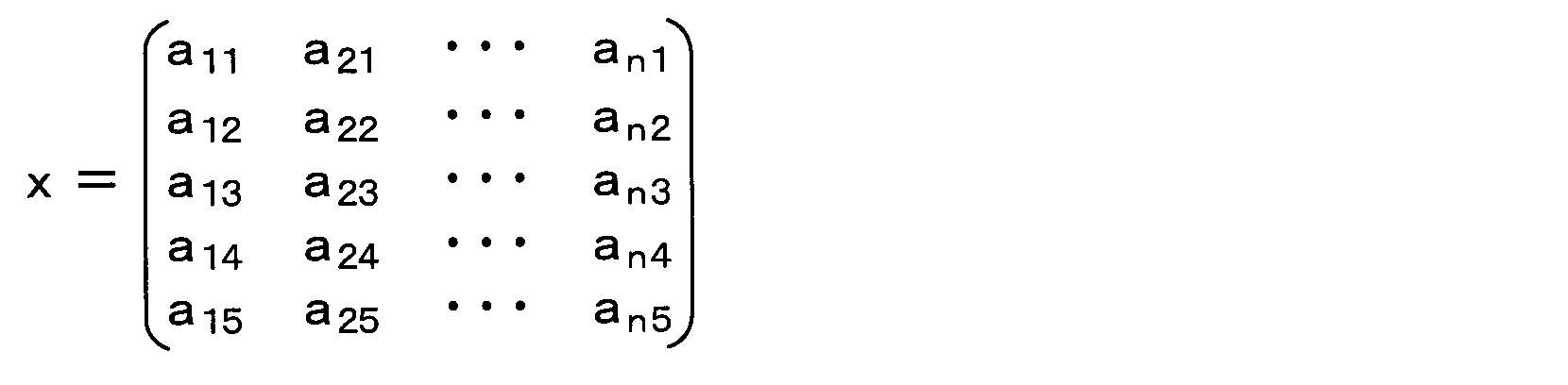
続いて、本実施形態にかかるタイヤ装置100および通信センター200を含めたタイヤシステムの作動について、図6~図7を参照して説明する。
まず、各車輪のタイヤ側装置1では、波形処理部1bにて、図6に示すデータ送信処理を実行している。この処理は、所定の制御周期ごとに実行される。
ステップS100では、振動センサ部1aの検出信号の入力処理を行う。この処理は、続くステップS110において、タイヤ3が1回転するまでの期間継続される。そして、振動センサ部1aの検出信号をタイヤ1回転分入力すると、その後のステップS120に進み、入力したタイヤ1回転分の振動センサ部1aの検出信号の時間軸波形の特徴量を抽出する。
なお、タイヤ3が1回転したことについては、振動センサ部1aの検出信号の時間軸波形に基づいて判定している。すなわち、検出信号は図4に示した時間軸波形を描くことから、検出信号の第1ピーク値や第2ピーク値を確認することでタイヤ3の1回転を把握することができる。
また、路面状態が検出信号の時間軸波形の変化として特に現れるのが、「踏み込み領域」、「蹴り出し前領域」、「蹴り出し領域」を含めたその前後の期間である。このため、この期間中のデータが入力されていれば良く、必ずしもタイヤ1回転中における振動センサ部1aの検出信号すべてのデータを入力していなくても良い。例えば、「踏み込み前領域」や「蹴り出し後領域」については、「踏み込み領域」の近傍や「蹴り出し領域」の近傍のデータがあれば良い。このため、振動センサ部1aの検出信号のうちの振動レベルが閾値よりも小さくなる領域については、「踏み込み前領域」や「蹴り出し後領域」の中でも路面状態の影響を受け難い期間として、検出信号の入力を行わないようにしても良い。
また、ステップS120で行う特徴量の抽出については、上述した通りの手法によって行っている。
そして、ステップS130に進む。ステップS130では、生波形計測モードであるか否かを判定する。生波形計測モードは、路面データとして特徴量に加えて振動センサ部1aの検出信号の生波形の送信が要求されているモードである。後述するように、受信機21側において、周辺装置22が取得した環境データに基づいてサポートベクタの学習を行うべき状況を判定しており、そのような状況であるとの判定結果であった場合に、データ通信部21aを通じてリクエスト信号が送信される。波形処理部1bは、そのリクエスト信号を受信すると、生波形計測モードであると判定する。
ここで否定判定された場合には、サポートベクタの学習を行うべき状況ではないため、ステップS140に進み、通常行われる路面状態の判別のためのデータ送信を実行すべく、今回の制御周期の際に抽出した特徴量を含む路面データをデータ通信部1cに伝える。これにより、データ通信部1cより、特徴量を含む路面データが送信される。
また、ステップS130で肯定判定された場合には、サポートベクタの学習を行うべき状況である。このため、ステップS150に進み、サポートベクタを学習するためのデータ送信を実行すべく、今回の制御周期の際に抽出した特徴量に加えて生波形データを含む路面データをデータ通信部1cに伝える。これにより、データ通信部1cより、特徴量に加えて生波形データを含む路面データが送信される。
一方、受信機21では、図7に示す路面状態判別処理、図8に示す環境判定処理、図9に示す学習データ送信処理、および、図11に示す学習データ更新処理が行われる。基本的には、路面状態判別処理は路面判定部21cによって行われ、環境判定処理、学習データ送信処理、学習データ更新処理は環境判定部21dや学習データ通信部21eにて行われるが、受信機21に備えられる各部が協働して各処理を実行すれば良い。これらの処理は、タイマ割込み処理等により、各処理それぞれに対して決められた制御周期ごとに実行される。さらに、通信センター200では、図10に示す学習処理を実行する。この処理も、通信センター200において所定の制御周期毎に実行される。
なお、環境判定処理、学習データ送信処理、学習処理、学習データ更新処理は、それぞれ対応した処理である。具体的には、環境判定処理に対応して学習データ送信処理が実行され、学習データ送信処理に対応して学習処理が実行され、さらに学習処理に対応して学習データ更新処理が実行される。このため、以下では、路面状態判別処理の説明を行ったのち、環境判定処理、学習データ送信処理、学習処理、学習データ更新処理の順で説明を行う。
まず、図7に示す路面状態判別処理では、ステップS200において、データ受信処理が行われる。この処理は、データ通信部21aが路面データを受信したときに、その路面データを路面判定部21cが取り込むことによって行われる。データ通信部21aがデータ受信を行っていないときには、路面判定部21cは何も路面データを取り込むことなく本処理を終えることになる。
この後、ステップS210に進み、特徴量を含む路面データのデータ受信が有ったか否かを判定し、受信していた場合にはステップS220に進み、受信していなければ受信するまでステップS200、S210の処理が繰り返される。なお、ここでは、特徴量を含む路面データを受信したことを判定しており、生波形データも含む路面データを受信しても、受信していないこととしている。しかしながら、生波形データが含まれた路面データについても、特徴量に関するデータを抽出することで路面状態の判別に用いることができるため、生波形データが含まれた路面データであっても受信したものとしても良い。
そして、ステップS220に進み、路面状態の判別を行う。路面状態の判別については、受信した路面データに含まれる特徴量と、路面判定部21cに保存された路面の種類別のサポートベクタとを比較することで行う。例えば、特徴量を路面の種類別の全サポートベクタとの類似度を求め、最も類似度が高かったサポートベクタの路面を現在の走行路面と判別している。
例えば、特徴量を路面の種類別の全サポートベクタとの類似度の算出は、次のような手法によって行うことができる。
上記したように特徴量を表す行列式Xについて、特徴量の行列式をX(r)、サポートベクタの行列式をX(s)とし、それぞれの行列式の各要素となるパワースペクトル値aikをa(r)ik,a(s)ikで表すとする。その場合、特徴量の行列式X(r)とサポートベクタの行列式X(s)は、それぞれ次のように表される。
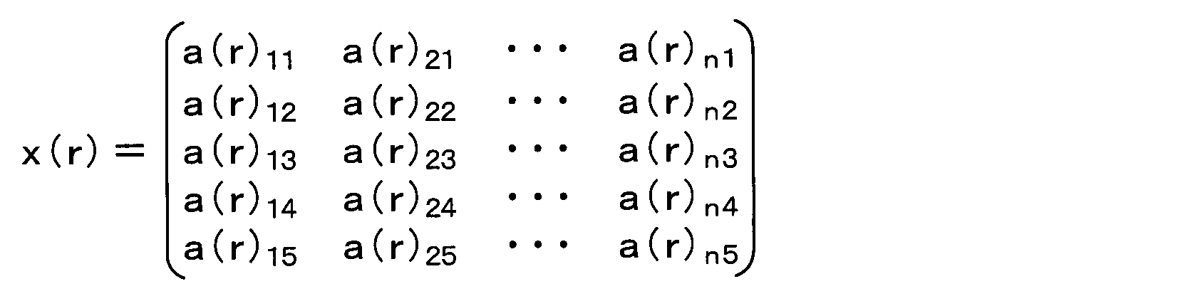

例えば、図12に示すように、振動センサ部1aの検出信号の時間軸波形について、今回のタイヤ3の回転時の時間軸波形とサポートベクタの時間軸波形それぞれを所定の時間幅Tの時間窓で各区画に分割する。図示例の場合、各時間軸波形を5つの区画に分割しているため、n=5となり、iは、1≦i≦5で表される。ここで、図中に示したように、今回のタイヤ3の回転時の各区画の特徴ベクトルXiをXi(r)、サポートベクタの各区画の特徴ベクトルをXi(s)とする。その場合、各区画の特徴ベクトルXiが示す座標間の距離Kyzについては、今回のタイヤ3の回転時の各区画の特徴ベクトルXi(r)を含む横の升とサポートベクタの各区画の特徴ベクトルXi(s)を含む縦の升とが交差する升のように示される。なお、距離Kyzについて、yはXi(s)におけるiを書き換えたものであり、zはXi(r)におけるiを書き換えたものである。なお、実際には、車速に応じて、今回のタイヤ3の回転時とサポートベクタとの区画数は異なったものとなり得るが、ここでは等しくなる場合を例に挙げてある。
本実施形態の場合、5つの特定周波数帯域に分けて特徴ベクトルを取得している。このため、時間軸と合わせた6次元空間において各区画の特徴ベクトルXiが表されることとなり、区画同士の特徴ベクトルがXi示す座標間の距離は、6次元空間における座標間の距離となる。ただし、各区画の特徴ベクトルが示す座標間の距離については、特徴量とサポートベクタとが似ているほど小さく、似ていないほど大きくなることから、当該距離が小さいほど類似度が高く、距離が大きいほど類似度が低いことを示している。
例えば、時分割によって区画1~nとされている場合、区画1同士の特徴ベクトルが示す座標間の距離Kyzについては、次式で示される。

なお、ここでは類似度に対応する値として各区画の特徴ベクトルが示す2つの座標間の距離Kyzの総和Ktotalを用いているが、類似度を示すパラメータとして他のものを用いることもできる。例えば、類似度を示すパラメータとして、総和Ktotalを区画数で割って求めた距離Kyzの平均値である平均距離Kaveを用いることができる。また、特許文献1に示されているように、様々なカーネル関数を用いて類似度を求めることもできる。また、特徴ベクトルのすべてを用いるのではなく、その中から類似度の低いパスを除いて類似度の演算を行うようにしても良い。
次に、受信機21が実行する環境判定処理について説明する。
図8に示すように、ステップS300において、データ受信処理が行われる。この処理は、環境判定部21dが周辺装置22から環境データを受信することにより行っている。環境判定部21dがデータ受信を行っていないときには、環境判定部21dは何も環境データを取り込むことなく本処理を終えることになる。
この後、ステップS310に進んでデータ受信が有ったか否かを判定し、受信していた場合にはステップS320に進み、受信していなければ受信するまでステップS300、S310の処理が繰り返される。
そして、ステップS320にて、環境データに基づいてサポートベクタの学習を行うべき状況であるか否かを判定する。ここで、上記した「サポートベクタの学習を行うべき状況」に該当する場合には肯定判定されてステップS330以降の処理に進み、該当しない場合には否定判定されてステップS300、S310の処理を繰り返す。
ステップS330では、「サポートベクタの学習を行うべき状況」と判定されたときの状況の種類のデータを記憶する。このデータは、例えば、次にステップS320で肯定判定されてステップS330の処理が実行されることで上書きされるまで記憶される。そして、ステップS340に進み、データ通信部21aに対してリクエスト信号の送信を指示して処理を終了する。これにより、データ通信部21aを通じて各タイヤ側装置1にリクエスト信号が伝えられる。
次に、受信機21が実行する学習データ送信処理について説明する。
図9に示すように、ステップS400において、データ受信処理が行われる。この処理は、データ通信部21aが路面データを受信したときに、その路面データを学習データ通信部21eが取り込むことによって行われる。データ通信部21aがデータ受信を行っていないときには、学習データ通信部21eは何も路面データを取り込むことなく本処理を終えることになる。
この後、ステップS410に進み、データ受信が有ったか否かを判定し、受信していた場合にはステップS420に進み、受信していなければ受信するまでステップS400、S410の処理が繰り返される。なお、ここでは特徴量に加えて生波形データを含む路面データを受信したことを判定しており、生波形データを含んでいない路面データを受信しても、受信していないこととしている。
そして、ステップS420にて、学習を行うべき状況と判定したときの路面データに加えて、環境判定部21dが上記した環境判定処理で記憶しておいたサポートベクタの学習を行うべき状況のデータと自車両のID情報などの車両データを追加したデータを作成する。その後、ステップS430に進み、ステップS420で作成したデータを学習データ通信部21eより通信センター200に送信する。これにより、外部通信機25を通じて、車両外部に備えられる通信センター200に、特徴量に加えて生波形データを含めた路面データと状況の種類のデータ、および、他車両と区別するための車両データが伝えられる。そして、これらの路面データと状況の種類のデータ、および、車両データが通信センター200に蓄積される。
続いて、通信センター200が実行する学習処理について説明する。
図10に示すように、ステップS500において、データ受信処理が行われる。この処理では、図9のステップS430で送信されたデータを受信する処理を行う。そして、ステップS510に進み、ステップS500で受信したデータに基づいて、車両ごとに、状況の種類別に路面データから特徴量や生波形データを読み取り、それらを解析すると共に各種演算を行うことで状況の種類別にサポートベクタを学習演算する。
その後、ステップS520に進み、学習演算結果に基づいて、データ更新の必要性があるか否かを判定する。例えば、学習演算のために収集されているデータ量が少なくてサポートベクタが得られていない場合や学習演算の結果が現状保存されているサポートベクタから変わっていない場合などには、データ更新の必要性が無いと判定される。そして、サポートベクタが得られていて、現在保存されているサポートベクタと異なるサポートベクタが得られた場合のように、ステップS520で肯定判定された場合には、ステップS530に進む。これにより、車両側に自身のデータであることを判別するための車両データと共に状況の種類と紐付けしたサポートベクタのデータ送信が行われる。さらに、この車両データや状況の種類と紐付けしたサポートベクタや路面データが示す路面状態を通信センター200でも蓄積しておく。これにより、車両データ毎、つまり車両毎のサポートベクタの学習データやその車両の走行路面の路面状態のデータなどを蓄積することができ、蓄積したデータを有効に活用することが可能となる。また、ステップS520で否定判定された場合には、そのまま処理が終了となる。
続いて、受信機21が実行する学習データ更新処理について説明する。
図11に示すように、ステップS600において、データ受信処理が行われる。この処理では、図10のステップS530で送信されたデータを受信する処理を行う。この後、ステップS610に進み、ステップS600で受信したデータに基づいて、サポートベクタ保存部21bに現在保存されているサポートベクタを更新する必要があるか否かを判定する。ここで、受信したデータに、サポートベクタ保存部21bに現在保存されているサポートベクタと異なるサポートベクタが含まれている場合には、更新する必要があると判定されてステップS620に進む。
そして、ステップ620において、サポートベクタ保存部21bにデータ送信を行うことで、サポートベクタ保存部21bに保存されているデータの更新を行い、処理を終了する。また、受信したデータに、サポートベクタ保存部21bに現在保存されているサポートベクタと異なるサポートベクタが含まれていない場合のように、ステップS610で否定判定された場合には、データ更新を行うことなく処理を終了する。
以上説明したように、本実施形態のタイヤ装置100および通信センター200を含めたタイヤシステムでは、車両に備えられる周辺装置22にて環境データを取得し、この環境データに基づいてサポートベクタの学習を行うべき状況であることを判定している。そして、サポートベクタの学習を行うべき状況である場合には、状況の種類と紐付けして特徴量や生波形データを含む路面データを通信センター200に送り、通信センター200においてサポートベクタの学習演算を行わせている。このため、通信センター200から学習結果を車両側に伝えることで、サポートベクタ保存部21bに、初期データとして保存しているサポートベクタ以外にも、状況に合わせてサポートベクタを更新していくことができる。つまり、通信センター200を利用して、納車時よりもアルゴリズムを進化させることが可能となる。
したがって、事前学習した保存データのみでは対応できない状況においても、適切に路面状態の判別が行えるようにできるタイヤ装置100およびそれを有するタイヤシステムとすることが可能となる。
(第2実施形態)
第2実施形態について説明する。本実施形態は、第1実施形態に対してサポートベクタをタイヤ側装置1にて保存するようにしたものであり、その他については第1実施形態と同様であるため、第1実施形態と異なる部分についてのみ説明する。
第2実施形態について説明する。本実施形態は、第1実施形態に対してサポートベクタをタイヤ側装置1にて保存するようにしたものであり、その他については第1実施形態と同様であるため、第1実施形態と異なる部分についてのみ説明する。
図13に示すように、本実施形態では、タイヤ側装置1にサポートベクタ保存部1eが備えられており、タイヤ側装置1で路面状態の判別が行えるようになっている。なお、納車時において、サポートベクタ保存部1eに予め保存されているサポートベクタのデータについては、第1実施形態において説明したサポートベクタ保存部21bと同様である。
このような構成においては、タイヤ側装置1の波形処理部1bにおいて、振動センサ部1aの検出信号から抽出した特徴量とサポートベクタ保存部1eの保存データに基づいて、路面状態を判別することができる。そして、データ通信部1cより路面状態の判別結果を示すデータを受信機21に伝え、路面判定部21cにおいて、タイヤ側装置1から伝えられたデータが示す判別結果に基づいて路面状態を判別し、それを報知装置24へ伝える。
また、受信機21から環境判定部21dの環境データに基づく路面データの要求があると、タイヤ側装置1より特徴量に加えて生波形データを含めた路面データが送信され、受信機21および外部通信機25を通じて通信センター200に伝えられる。これにより、第1本実施形態と同様に、通信センター200をクラウドの提供元コンピュータとしてサポートベクタの学習演算が行われ、その学習演算の結果が外部通信機25を通じて受信機21に伝えられる。さらに、学習データ通信部21eにてサポートベクタ保存部1eに現在保存されているサポートベクタを更新する必要があると判定されると、データ通信部21aより更新すべきサポートベクタのデータがタイヤ側装置1に伝えられる。そして、サポートベクタ保存部1eに保存されているサポートベクタに加えて新たなサポートベクタのデータが保存される。
本実施形態のタイヤ装置100においては、基本的には、上記のような動作を行うこと以外については、タイヤ側装置1や受信機21および通信センター200で第1実施形態と同様の処理、すなわち図6~図11と同様の処理を行う。
ただし、図6のステップS120では、特徴量の抽出に加えて路面状態の判別も行っており、ステップS140では、特徴量を含む路面データについても送っても良いが、路面状態の判別結果を示すデータを送っている。また、学習データ更新処理として、図11に示す処理に代えて図14に示す処理を行っている。具体的には、図14に示すステップS700~S710では、図11に示すステップS600~S610と同様の処理を行い、その後ステップS720において、タイヤ側装置1へ更新すべきサポートベクタのデータの送信を行う。なお、ステップS710では、サポートベクタ保存部1eに現在保存されているサポートベクタを更新する必要があるか否かを判定することになる。これについては、通信センター200から伝えられるデータ内に、更新すべき内容を有していることを表すデータを含めておき、当該データが含まれていた場合に、受信機21において更新する必要があると判定されるようにすれば良い。
このように、タイヤ側装置1にサポートベクタ保存部1eを備えて路面状態の判別まで行うこともできる。そして、タイヤ側装置1に備えたサポートベクタ保存部1eに記憶されているサポートベクタを通信センター200での学習結果に基づいて更新するようにしても良い。このようにしても、第1実施形態と同様の効果を得ることができる。
(第3実施形態)
第3実施形態について説明する。本実施形態は、第1実施形態で説明したように通信センター200に蓄積したデータを有効活用するものであり、通信センター200でのデータの蓄積などについては第1、第2実施形態と同様であるため、第1、第2実施形態と異なる部分についてのみ説明する。
第3実施形態について説明する。本実施形態は、第1実施形態で説明したように通信センター200に蓄積したデータを有効活用するものであり、通信センター200でのデータの蓄積などについては第1、第2実施形態と同様であるため、第1、第2実施形態と異なる部分についてのみ説明する。
第1実施形態で説明したように、各車両から伝えられた路面データ、状況の種類のデータ、および、車両データに加えて、学習データとなるサポートベクタが通信センター200に蓄積されていく。このため、同じ車種の車両や同じタイヤを有する車両の場合、通信センター200で蓄積された各種データを流用できる可能性がある。このため、先に車両から伝えられた各種データや演算したサポートベクタを通信センター200で蓄積しておいた場合に、それを他の車両でデータ流用できるようにする。具体的には、他の車両が図15および図16に示す処理を実行することで、データ流用を行う。
なお、他の車両についても、図2に示したようなタイヤ側装置1や車体側システム2が備えられている。このため、タイヤ側装置1においては、図6に示す処理を実行しており、車体側システム2では、図7~図9、図11に示す処理を実行している。また、通信センター200では、図10に示す処理を実行している。そして、それに加えて、車体側システム2では、図15に示すダウンロード要求処理を実行しており、通信センター200では、図16に示すデータダウンロード処理を実行する。
まず、車体側システム2は、図15に示すように、ステップS800において、データ受信処理を行う。この処理は、図7のステップS200と同様の処理である。続いて、ステップS810において、学習済みデータと違うか否かを判定する。例えば、受信したデータに含まれる特徴量とサポートベクタ保存部21bに保存されている全サポートベクタとの類似度を演算する。そして、類似度が低いものしかない場合には、学習済みのサポートベクタには現在走行中の路面の路面状態として該当する路面の種類に応じたものが含まれていないと考えられるため、学習済みデータと違うと判定するようにしている。また、ステップS800でタイヤ側装置1から受信したデータではなく、周辺装置22から得られる環境データが、学習済みのサポートベクタを抽出した学習条件と異なる条件を示していた場合に、学習済みデータと違うと判定しても良い。
ここで、ステップS810で否定判定されればそのまま処理を終了し、肯定判定されればステップS820に進む。そして、ステップS820において、クラウドの提供元コンピュータとなる通信センター200に、他車両と区別するための車両データと共に学習データのリクエスト信号を送信する。車両データについては、上記と同様、自車両と他の車両との区別を行えるデータで有れば良いが、ここではタイヤ3の種類など、より細かいデータを含めることで、より自車両の状況に対応した学習データの要求を行うことが可能となる。また、状況の種類のデータについても送信するようにすれば、状況の種類に応じた学習データの要求を行うことも可能となる。その後、後述する図16に示す処理に基づいて、通信センター200から、学習データが送られてくるため、ステップS830において、その学習データをダウンロードする。
一方、通信センター200では、図16に示すように、ステップS900において、車両側からの学習データの要求信号を受け取ったか否かを判定する。ここで否定判定されればそのまま処理を終了し、肯定判定されればステップS910に進む。上記したステップS820において、学習データの要求信号が送信されていれば、本ステップで肯定判定されることになる。
続いて、ステップS910では、学習データの要求信号と共に送られてきた車両データの受信処理を行う。そして、ステップS920に進み、車両データと類似の学習データを探索する。通信センター200に蓄積されているデータの中から、例えば、同じ車種の車両、同じタイヤの車両、もしくはその両方が該当する車両の学習データが類似の学習データとして探索される。この後、ステップS930に進み、学習データの要求信号を送信してきた車両に対して、学習データのダウンロードを行わせるべく、通信センター200に蓄積されている各種データやサポートベクタの学習データの送信を行う。このときにも、学習データと共に車両データも送るようにすることで、ダウンロードを行わせる車両を特定できるようにしている。
このようにして、通信センター200に蓄積されている各種データやサポートベクタの学習データが他の車両に伝えられるため、他の車両では、そのデータを有効活用して、路面状態の判別などを行うことができる。特に、車両データに加えて、状況の種類のデータも含ませるようにすれば、状況の種類も加味した学習データを他の車両に伝えることができ、より的確に路面状態の判別などを行うことが可能となる。
また、通信センター200で、先の車両の走行路面の路面状態のデータなども蓄積してあるため、そのデータについても他の車両に伝えるようにすれば、他の車両では、自身が走行していない路面についても、路面状態のデータを事前に知ることが可能となる。その場合、他の車両では、路面状態を判別するためのデータ取得を行わなくても済むようにできる。
なお、第2実施形態の場合、タイヤ側装置1にサポートベクタ保存部1eが備えられていることから、タイヤ側装置1において、学習済みデータと違うか否かの判定を行うようにすれば良い。そして、学習済みデータと違っていれば、タイヤ側装置1から車体側システム2にリクエスト信号を送信するようにすれば良い。
(第4実施形態)
第4実施形態について説明する。本実施形態は、第1実施形態で説明した「サポートベクタの学習を行うべき状況」の具体例を挙げたものであり、その他については第1実施形態と同様であるため、第1実施形態と異なる部分についてのみ説明する。
第4実施形態について説明する。本実施形態は、第1実施形態で説明した「サポートベクタの学習を行うべき状況」の具体例を挙げたものであり、その他については第1実施形態と同様であるため、第1実施形態と異なる部分についてのみ説明する。
第1実施形態で説明したように、サポートベクタを抽出した学習条件と異なる条件となった場合、その条件でも学習データを得るようにするのが好ましい「サポートベクタの学習を行うべき状況」となる。本実施形態では、その「サポートベクタの学習を行うべき状況」の具体例を挙げて説明する。また、本実施形態では、周辺装置22の環境データに基づいて、車体側システム2で「サポートベクタの学習を行うべき状況」と判定されたときに、車体側システム2からタイヤ側装置1に対して生波形データ等の路面データの送信指示を出す場合について説明する。ただし、これは一例を示したのであり、第1実施形態で説明したような手法としても良い。すなわち、タイヤ側装置1から生波形データ等の路面データを受信しておき、車体側システム2にて「サポートベクタの学習を行うべき状況」と判定したときに、既に受信してある路面データを通信センター200に伝えるという形態であっても良い。
まず、受信機21では、環境判定部21d等において、図17~図24に示す各処理を実行する。これらの処理は、第1実施形態で説明した図8に示す環境判定処理を、判定する内容別に区分けして行われるようにしたものであり、ここでは独立したフローとして、例えばタイマ割り込み処理として実行されるようにしているが、1つのフローとしても良い。
図17では、ステップS1000aにおいて、外気温の温度情報の取得処理を行う。この処理は、例えばナビゲーションシステムを周辺装置22として、温度情報を取得することにより行われる。そして、ステップS1010aに進み、先ほど取得した外気温が0℃以下であるか否かを判定する。すなわち、サポートベクタを学習した状況が例えば25℃程度の環境温度であった場合において、環境温度から所定温度以上の温度差が生じるような環境であった場合、ここでは、外気温が0℃以下である場合には「サポートベクタの学習を行うべき状況」としている。ここで肯定判定されると、ステップS1020aに進み、タイヤ側装置1や通信センター200側に学習開始指令のリクエスト信号を出力して処理を終了する。
図18では、ステップS1000bにおいて、天候情報の取得処理を行う。この処理も、例えばナビゲーションシステムを周辺装置22として、天候情報を取得することにより行われる。そして、ステップS1010bに進み、先ほど取得した天候が学習経験の無い天候、例えば大雨、強風などであるか否かを判定する。すなわち、サポートベクタを学習した状況が例えば単位時間あたりの降雨量が所定量以下、風速が所定値以下の天候であった場合において、降雨量や風速が学習した状況を上回っている環境であった場合には「サポートベクタの学習を行うべき状況」としている。ここで肯定判定されると、ステップS1020bに進み、上記したステップS1020aと同様の処理を実行して処理を終了する。なお、ここでは天候情報の一例として大雨、強風を例に挙げているが、勿論他の情報についても適用可能である。
図19では、ステップS1000cにおいて、季節情報の取得処理を行う。この処理も、例えばナビゲーションシステムを周辺装置22として、現在の季節情報を取得すること、もしくは、現在の日時情報を取得することにより行われる。そして、ステップS1010cに進み、先ほど取得した現在の季節が学習した季節とは別の季節であるか否かを判定する。すなわち、サポートベクタを学習した状況が例えば春季であった場合において、現在の季節が冬季のような環境であった場合には「サポートベクタの学習を行うべき状況」としている。ここで肯定判定されると、ステップS1020cに進み、上記したステップS1020aと同様の処理を実行して処理を終了する。
図20では、ステップS1000dにおいて、タイヤ情報の取得処理を行う。この処理は、受信機21を周辺装置22として、例えばタイヤ3の種類が変更されたときに受信機21に登録しておいた内容を読み出すことにより行われる。そして、ステップS1010dに進み、先ほど取得したタイヤ情報が示すタイヤ3の種類が学習したときとは別の種類であるか否か、例えば純正タイヤからの変更があるか否かを判定する。すなわち、サポートベクタを学習した状況では例えば純正タイヤであった場合において、現在のタイヤ3の種類が純正タイヤでは無かった場合には「サポートベクタの学習を行うべき状況」としている。ここで肯定判定されると、ステップS1020dに進み、上記したステップS1020aと同様の処理を実行して処理を終了する。なお、ここでは純正タイヤからの変更を例に挙げたが、変更後の学習が完了した場合、そのタイヤ情報も学習済みのタイヤ情報として新たに追加することもできる。その場合、ステップS1010dの処理では、学習したときのタイヤ3の種類に、純正タイヤに加えて、新たに学習済みのタイヤ情報も含めるようにすれば良い。
図21では、ステップS1000eにおいて、タイヤ空気圧の取得処理を行う。この処理は、TPMSを周辺装置22として、例えばTPMSからタイヤ情報としてタイヤ空気圧の情報を取得することにより行われる。そして、ステップS1010eに進み、先ほど取得したタイヤ空気圧が所定の閾値以下になっているか否かを判定する。すなわち、サポートベクタを学習した状況では例えば適正タイヤ空気圧であった場合において、現在のタイヤ空気圧が閾値以下まで低下していた場合には「サポートベクタの学習を行うべき状況」としている。ここで肯定判定されると、ステップS1020eに進み、上記したステップS1020aと同様の処理を実行して処理を終了する。
図22では、ステップS1000fにおいて、路面状態の取得処理を行う。この処理は、例えば車載カメラまたはブレーキECU23を周辺装置22として、車載カメラで取得した画像データの解析に基づく路面状態の推定結果を取得したり、ブレーキECU23による路面状態の推定結果を取得することにより行われる。そして、ステップS1010fに進み、先ほど取得した路面状態が学習経験の無い未学習路面になっているか否かを判定する。すなわち、サポートベクタを学習した状況は例えばアスファルト路等のドライ路面、ウェット路面、凍結路、積雪路などの学習設定路面とされているため、岩石路面などについては「サポートベクタの学習を行うべき状況」としている。ここで肯定判定されると、ステップS1020fに進み、上記したステップS1020aと同様の処理を実行して処理を終了する。
図23では、ステップS1000gにおいて、タイヤ摩耗状態に相当するタイヤ3の残り溝の検出処理を行う。この処理は、例えば受信機21やメータECUを周辺装置22として、タイヤ交換を行ったことを受信機21に登録しておき、登録時からの走行距離をメータECUから取得し、これらからタイヤ3の残り溝を算出することで行われる。そして、ステップS1010gに進み、先ほど取得したタイヤ3の残り溝が閾値以下であるか否かを判定する。すなわち、サポートベクタを学習した状況ではタイヤ3の残り溝が十分に有る状態であるため、残り溝が閾値以下の場合には「サポートベクタの学習を行うべき状況」としている。ここで肯定判定されると、ステップS1020gに進み、上記したステップS1020aと同様の処理を実行して処理を終了する。
図24では、ステップS1000hにおいて、加減速度情報の取得処理を行う。この処理は、例えばブレーキECU23やメータECUを周辺装置22として、これらが扱っている車速から加減速度を算出することで行われる。そして、ステップS1010hに進み、先ほど取得した加減速度が所定の閾範囲外であるか否かを判定する。すなわち、サポートベクタを学習した状況では加減速度が所定の閾範囲内とされているため、加減速度が閾範囲外の場合には「サポートベクタの学習を行うべき状況」としている。ここで肯定判定されると、ステップS1020hに進み、上記したステップS1020aと同様の処理を実行して処理を終了する。
このようにして、環境判定処理が行われ、ステップS1020a~S1020hにおいて、学習開始指令のリクエスト信号が出力されると、それに基づいて、タイヤ側装置1、車体側システム2および通信センター200が各種処理を実行する。
まず、タイヤ側装置1では、図25に示すデータ送信処理を実行する。図25に示すように、ステップS1100では、学習開始指令のリクエスト信号が有ったか否かを判定している。上記したように、車体側システム2より学習開始指令のリクエスト信号が出力されると、本ステップで肯定判定され、ステップS1110に進む。そして、タイヤ1回転分の生波形データを含む路面データを取得したのち、ステップS1120に進んでその路面データを車体側システム2にデータ送信する。なお、ステップS1110の処理は、上記した図6の各処理と同様の手法によって実行することができる。
そして、タイヤ側装置1より路面データが送信されると、車体側システム2は、図26に示す学習データ送信処理を実行する。まず、ステップS1200において、タイヤ側装置1から送信されてきた生波形データを含む路面データの受信処理を行い、その後、ステップS1210において、路面データを取得したか否かを判定する。ここで、ステップS1200において、路面データを受信できていなければそのまま処理を終了する。また、受信できていればステップS1220に進み、通信センター200にアップロードすべく、受信した路面データを学習データとして通信センター200に送信する処理を実行する。
さらに、通信センター200では、図27に示す学習処理を実行する。まず、ステップS1300において、学習開始指令のリクエスト信号が有ったか否かを判定している。上記したように、車体側システム2より学習開始指令のリクエスト信号が出力されると、本ステップで肯定判定され、ステップS1310に進む。そして、車体側システム2から送信された生波形データを含む路面データを取得したか否かを判定し、取得したらステップS1320に進んで学習を開始し、学習を終えると、その結果を車体側システム2に伝えてサポートベクタ保存部21bにダウンロードする。このときの通信センター200の処理方法については、図10のステップS510~S530と同様であり、それに基づいて車体側システム2がサポートベクタ保存部21bにデータダウンロードする方法も、図11のステップS600~S620と同様である。
以上説明したように、様々な「サポートベクタの学習を行うべき状況」であるか否かを判定し、それに基づいて、学習した状況では無い状況についても、新たに学習データを追加、更新していくことが可能となる。これにより、より様々な状況についての学習データを得ることが可能となり、より的確な路面状態判別を行うことが可能となる。
(第5実施形態)
第5実施形態について説明する。本実施形態は、第1~第4実施形態に対して、タイヤ側装置1において路面状態の変化を検出し、路面状態の変化が有った場合に、その路面変化を車体側システム2に伝えて、学習開始させるようにするものである。本実施形態の他については第1~第4実施形態と同様であるため、第1~第4実施形態と異なる部分についてのみ説明する。
第5実施形態について説明する。本実施形態は、第1~第4実施形態に対して、タイヤ側装置1において路面状態の変化を検出し、路面状態の変化が有った場合に、その路面変化を車体側システム2に伝えて、学習開始させるようにするものである。本実施形態の他については第1~第4実施形態と同様であるため、第1~第4実施形態と異なる部分についてのみ説明する。
本実施形態では、タイヤ側装置1にて、振動センサ部1aの検出信号に基づいて路面状態の変化を検出し、その変化を車体側システム2に伝えるようにする。具体的には、タイヤ側装置1は、図28に示す路面変化検出処理を実行する。
まず、ステップS1400において、振動センサ部1aの検出信号の入力処理を行い、これがステップS1410において、タイヤ3が1回転するまでの期間継続される。そして、振動センサ部1aの検出信号をタイヤ1回転分入力すると、ステップS1420に進み、今回特徴量として、入力したタイヤ1回転分の加速度取得部10の検出信号の時間軸波形の特徴量を抽出する。このときの特徴量の抽出手法については、図6のステップS120と同様である。
この後、ステップS1430に進み、今回特徴量と前回特徴量とについて、図7のステップS220で説明した手法によって類似度を求め、例えば類似度を閾値Thと比較することで、路面状態の変化が有ったか否かを判定する。そして、ステップS1430で肯定判定されると、ステップS1440において路面状態の変化があったことを記憶しておく。さらに、ステップS1450に進み、今回特徴量を前回特徴量として特徴量保存部11bに保存して、処理を終了する。
また、タイヤ側装置1は、図29に示すデータ送信処理を実行している。まず、ステップS1500では、路面状態の変化があったとの判定が行われたか否かを判定する。この判定は、上記した図27のステップS1440において路面状態の変化があったことが記憶されているか否かに基づいて行われる。ここで肯定判定された場合にはステップS1510に進み、今回特徴量や生波形データを含む路面データと共に、路面状態の変化があったことを示すデータを車体側システム2に送信する。そして、ここで否定判定された場合にはステップS1520に進み、今回特徴量を含む路面データを送信する。
この後は、第1実施形態で説明した図7~図11に示す各処理を実行する。これら各処理については、第1実施形態とほぼ同様であるが、図8のステップS320において、タイヤ側装置1から路面状態の変化があったことを示すデータが送信されてきたことも、「サポートベクタの学習を行うべき状況」と判定されるようにしている。
このように、タイヤ側装置1において路面状態の変化を検出し、それを「サポートベクタの学習を行うべき状況」として車体側システム2に伝え、通信センター200にて、サポートベクタの学習を行わせることもできる。
(他の実施形態)
本開示は、上記した実施形態に準拠して記述されたが、当該実施形態に限定されるものではなく、様々な変形例や均等範囲内の変形をも包含する。加えて、様々な組み合わせや形態、さらには、それらに一要素のみ、それ以上、あるいはそれ以下、を含む他の組み合わせや形態をも、本開示の範疇や思想範囲に入るものである。
本開示は、上記した実施形態に準拠して記述されたが、当該実施形態に限定されるものではなく、様々な変形例や均等範囲内の変形をも包含する。加えて、様々な組み合わせや形態、さらには、それらに一要素のみ、それ以上、あるいはそれ以下、を含む他の組み合わせや形態をも、本開示の範疇や思想範囲に入るものである。
(1)例えば、上記実施形態では、振動検出部を構成する振動センサ部1aを加速度センサによって構成する場合を例示したが、他の振動検出を行うことができる素子、例えば圧電素子などによって構成することもできる。
(2)また、上記実施形態では、タイヤ側装置1から振動センサ部1aの検出信号に現れる路面状態を示す路面データとして、特徴量を含むデータを用いている。しかしながら、これも一例を示したに過ぎず、他のデータを路面データとして用いても良い。例えば、タイヤ3の1回転中の振動データに含まれる5つの領域R1~R5それぞれの振動波形の積分値データを路面データとしても良いし、検出信号そのものの生データを路面データとしても良い。
同様に、通信センター200に特徴量および生波形データを含む路面データを送るようにしているが、特徴量および生波形データのいずれか一方のみでも良い。また、タイヤ3の1回転中の振動データに含まれる5つの領域R1~R5それぞれの振動波形の積分値データを路面データとして通信センター200に送るようにしても良い。
(3)また、上記各実施形態では、車体側システム2に備えられる受信機21の路面判定部21cによって特徴量とサポートベクタとの類似度を求めて路面状態の判別を行っている。
しかしながら、これも一例を示したに過ぎず、車体側システム2のいずれかの場所、例えばブレーキECU23などのような他のECUによって類似度を求めたり、路面状態の判別を行ったり、指示信号の送信を行うようにしても良い。
(4)また、上記各実施形態では、サポートベクタの学習演算のために通信センター200を利用している。これは、学習演算を行う際のデータ量が膨大となることなどが理由であるが、例えば受信機21にサポートベクタの学習演算を行う機能を備えさせ、各車両で学習演算を実施できるようにしても良い。
ただし、通信センター200においては、各車両で得られない各種情報、例えば他車両のデータに基づいて判別した路面状態などを加味して、サポートベクタの学習演算を行うこともできる。そのため、通信センター200を利用することで、より精度良く更新に用いるサポートベクタの学習演算を行うことが可能となる。
さらに、上記各実施形態では、タイヤ側装置1と受信機21との間において双方向通信を行う構成としているが、必ずしも双方向通信を行う構成でなくても良い。例えば、受信機21にサポートベクタ保存部21bを備えた構成とする場合、周辺装置22の環境データに基づいてサポートベクタの更新を行うべきときに、タイヤ側装置1からの路面データに基づいてサポートベクタの学習演算を行う。サポートベクタの学習演算は、通信センター200で行われても良いし、受信機21に学習演算を行う機能を備えさせて受信機21などで行われるようにしても良い。このように、タイヤ側装置1から受信機21へのみデータ通信が行える一方向通信としても、サポートベクタの学習演算および更新を行うことが可能である。
(5)また、機械学習の一例として、サポートベクタの学習演算を例に挙げ、教師データとしてサポートベクタを例に挙げたが、公知となっている他の機械学習によって教師データの更新を行うものについても、本開示を適用できる。
また、上記各実施形態では、複数のタイヤ3のそれぞれに対してタイヤ側装置1を備えるようにしたが、少なくとも1つに備えられていればよい。
Claims (11)
- 車両に備えられるタイヤ(3)に取り付けられたタイヤ側装置(1)と、車体に備えられた車体側システム(2)とを有する路面状態判別装置であって、
前記タイヤ側装置は、
前記タイヤの振動の大きさに応じた検出信号を出力する振動検出部(1a)と、前記検出信号の波形に現れる路面状態を示す路面データを生成する波形処理部(1b)と、前記路面データを送信する第1データ通信部(1c)と、を備え、
前記車体側システムは、
前記第1データ通信部から送信された前記路面データを受信する第2データ通信部(21a)と、教師データを保存する保存部(21b)と、前記路面データと前記教師データとに基づいて前記車両の走行路面における路面状態を判別する路面判定部(21c)と、前記路面状態に関わる環境データを取得する周辺装置(22)と、前記環境データに基づいて前記教師データの学習演算を行うべき状況であるか否かの判定を行うと共に、前記教師データの学習演算を行うべき状況であるとの判定結果に基づいて、前記第2データ通信部を通じて前記タイヤ側装置にリクエスト信号を出力させる環境判定部(21d)と、を備え、
前記タイヤ側装置は、前記第1データ通信部にて前記リクエスト信号を受信すると、前記波形処理部にて前記路面データを生成すると共に、前記第1データ通信部を通じて前記路面データを前記車体側システムに送信し、
前記車体側システムは、前記タイヤ側装置から伝えられた路面データと前記環境データが示す前記学習演算を行うべき状況の種類とを用いた機械学習により前記教師データの更新データが学習演算されると、前記保存部に記憶された前記教師データに前記更新データを加味したデータを新たな教師データとして保存する路面状態判別装置。 - 前記タイヤ側装置は、前記第1データ通信部にて前記リクエスト信号を受信すると、前記路面データとして、前記タイヤの振動の特徴を示す特徴量と前記検出信号の生波形データの少なくとも一方を含むデータを生成し、前記第1データ通信部を通じて前記路面データを前記車体側システムに送信する請求項1に記載の路面状態判別装置。
- 車両に備えられるタイヤ(3)に取り付けられたタイヤ側装置(1)と、車体に備えられた車体側システム(2)とを有する路面状態判別装置であって、
前記タイヤ側装置は、
前記タイヤの振動の大きさに応じた検出信号を出力する振動検出部(1a)と、教師データを保存する保存部(1e)と、前記検出信号と前記教師データとに基づいて前記車両の走行路面における路面状態の判別を行うと共に該判別結果を示すデータの生成を行い、かつ、前記検出信号の波形に現れる路面状態を示す路面データの生成を行う波形処理部(1b)と、前記判別結果を示すデータや前記路面データを送信する第1データ通信部(1c)と、を有し、
前記車体側システムは、
前記第1データ通信部から送信された前記判別結果を示すデータや前記路面データを受信する第2データ通信部(21a)と、前記判別結果を示すデータに基づいて路面状態を判別する路面判定部(21c)と、前記路面状態に関わる環境データを取得する周辺装置(22)と、前記環境データに基づいて前記教師データの学習演算を行うべき状況であるか否かの判定を行うと共に、前記教師データの学習演算を行うべき状況であるとの判定結果に基づいて、前記第2データ通信部を通じて前記タイヤ側装置にリクエスト信号を出力させる環境判定部(21d)と、を有し、
前記タイヤ側装置は、前記第1データ通信部にて前記リクエスト信号を受信すると、前記波形処理部にて、前記路面データとして、前記タイヤの振動の特徴を示す特徴量と前記検出信号の生波形データの少なくとも一方を含むデータを生成すると共に、前記第1データ通信部を通じて前記路面データを前記車体側システムに送信し、
前記車体側システムは、前記タイヤ側装置から伝えられた前記路面データと前記環境データが示す前記学習演算を行うべき状況の種類とを用いた機械学習により前記教師データの更新データが学習演算されると、前記車体側システムを通じて前記タイヤ側装置に対して前記更新データを送信し、前記保存部に記憶された前記教師データに前記更新データを加味したデータを新たな教師データとして保存する路面状態判別装置。 - 前記車体側システムは、前記第2データ通信部が前記路面データを受信すると、該路面データに基づいて前記更新データの機械学習を行う請求項1ないし3のいずれか1つに記載の路面状態判別装置。
- 車両に備えられるタイヤ(3)に取り付けられたタイヤ側装置(1)と、車体に備えられた車体側システム(2)とを有する路面状態判別装置であって、
前記タイヤ側装置は、
前記タイヤの振動の大きさに応じた検出信号を出力する振動検出部(1a)と、前記検出信号の波形に現れる路面状態を示す路面データを生成する波形処理部(1b)と、前記路面データを送信する第1データ通信部(1c)と、を備え、
前記車体側システムは、
前記第1データ通信部から送信された前記路面データを受信する第2データ通信部(21a)と、教師データを保存する保存部(21b)と、前記路面データと前記教師データとに基づいて前記車両の走行路面における路面状態を判別する路面判定部(21c)と、を備え、
前記タイヤ側装置は、前記検出信号に基づいて路面状態の変化があったことを判定し、前記路面状態が変化したと判定すると、前記第1データ通信部より前記路面状態が変化したことを示すデータと共に前記路面データの送信を行い、
前記車体側システムは、前記路面状態が変化したことを示すデータを受信すると前記教師データの学習演算を行うべき状況であると判定し、前記路面データと前記路面状態が変化したという前記学習演算を行うべき状況の種類とを用いた機械学習により前記教師データの更新データが学習演算されると、前記保存部に記憶された前記教師データに前記更新データを加味したデータを新たな教師データとして保存する路面状態判別装置。 - 前記波形処理部は、前記タイヤの1回転中における前記検出信号の特徴量を抽出すると共に該特徴量を含む前記路面データを作成するものであり、前記タイヤの今回の回転時に抽出された前記特徴量を今回特徴量として、該今回特徴量と過去に抽出された前記特徴量である過去特徴量とに基づいて、路面状態が変化したことを判定する、請求項5に記載の路面状態判別装置。
- 前記車体側システムは、前記教師データの学習演算を行うべき状況であるか否かの判定を行うと共に、前記教師データの学習演算を行うべき状況であるとの判定結果に基づいて、前記第2データ通信部を通じて前記タイヤ側装置にリクエスト信号を出力させる環境判定部(21d)を有し、
前記タイヤ側装置は、前記第1データ通信部にて前記リクエスト信号を受信すると、前記波形処理部にて前記路面データを生成すると共に、前記第1データ通信部を通じて前記路面データを前記車体側システムに送信し、
前記車体側システムは、前記タイヤ側装置から伝えられた路面データと前記環境データが示す前記学習演算を行うべき状況の種類とを用いた機械学習により前記教師データの更新データが学習演算されると、前記保存部に記憶された前記教師データに前記更新データを加味したデータを新たな教師データとして保存する請求項5または6に記載の路面状態判別装置。 - 前記環境判定部は、前記環境データに基づき、前記学習データを学習した状況と異なる状況であるか否かを判定し、前記学習データを学習した状況と異なる状況であると、前記教師データの学習演算を行うべき状況であるとの判定結果を出す請求項1ないし4および7のいずれか1つに記載の路面状態判別装置。
- 前記環境判定部は、前記環境データとして、前記車両の走行環境、走行の仕方、タイヤ情報、天気情報、温度情報、季節情報、地域情報もしくは路面凍結情報の少なくとも1つに基づいて、前記学習データを学習した状況と異なる状況であるか否かを判定する請求項8に記載の路面状態判別装置。
- 請求項1ないし9いずれか1つに記載の路面状態判別装置と、
前記車体側システムとの間においてデータ通信を行う通信センター(200)と、を有するタイヤシステムであって、
前記車体側システムは、前記通信センターとの間の通信を行う外部通信機(25)を含み、該外部通信機を通じて前記通信センターに前記タイヤ側装置より受信した前記路面データを送信し、
前記通信センターは、前記外部通信機より前記路面データを受信すると、該路面データに基づいて前記更新データの機械学習を行い、前記更新データを前記外部通信機に伝えるタイヤシステム。 - 前記車体側システムもしくは前記タイヤ側装置では、前記路面データが前記保存部に保存してある学習済みデータと違っているか否かを判定し、前記学習済みデータと違っていると判定すると、前記車体側システムより前記通信センターに対して、前記車両に関するデータである車両データを伝えることで、前記通信センターに蓄積されている学習データを要求する請求項10に記載のタイヤシステム。
Priority Applications (1)
| Application Number | Priority Date | Filing Date | Title |
|---|---|---|---|
| US16/859,799 US11549809B2 (en) | 2017-10-30 | 2020-04-27 | Road surface state determination device and tire system |
Applications Claiming Priority (4)
| Application Number | Priority Date | Filing Date | Title |
|---|---|---|---|
| JP2017-209402 | 2017-10-30 | ||
| JP2017209402 | 2017-10-30 | ||
| JP2018113705A JP6733707B2 (ja) | 2017-10-30 | 2018-06-14 | 路面状態判別装置およびそれを備えたタイヤシステム |
| JP2018-113705 | 2018-06-14 |
Related Child Applications (1)
| Application Number | Title | Priority Date | Filing Date |
|---|---|---|---|
| US16/859,799 Continuation US11549809B2 (en) | 2017-10-30 | 2020-04-27 | Road surface state determination device and tire system |
Publications (1)
| Publication Number | Publication Date |
|---|---|
| WO2019088024A1 true WO2019088024A1 (ja) | 2019-05-09 |
Family
ID=66333086
Family Applications (1)
| Application Number | Title | Priority Date | Filing Date |
|---|---|---|---|
| PCT/JP2018/040125 Ceased WO2019088024A1 (ja) | 2017-10-30 | 2018-10-29 | 路面状態判別装置およびそれを備えたタイヤシステム |
Country Status (1)
| Country | Link |
|---|---|
| WO (1) | WO2019088024A1 (ja) |
Cited By (8)
| Publication number | Priority date | Publication date | Assignee | Title |
|---|---|---|---|---|
| CN110182215A (zh) * | 2019-05-23 | 2019-08-30 | 南京航空航天大学 | 一种汽车经济性巡航控制方法及装置 |
| WO2021045051A1 (ja) * | 2019-09-04 | 2021-03-11 | 株式会社デンソー | タイヤ装置 |
| WO2021080011A1 (ja) * | 2019-10-25 | 2021-04-29 | 株式会社デンソー | 制御装置 |
| WO2021210229A1 (ja) * | 2020-04-14 | 2021-10-21 | Kyb株式会社 | 学習済みモデル生成方法および路面性状判定装置 |
| US11198336B2 (en) | 2017-10-30 | 2021-12-14 | Denso Corporation | Transmission and receiving arrangement for a tire pressure detection device |
| US11376901B2 (en) * | 2018-03-02 | 2022-07-05 | Denso Corporation | Road surface condition determination device performing sensing based on different sensing conditions |
| WO2023189971A1 (ja) * | 2022-03-31 | 2023-10-05 | Kyb株式会社 | 演算装置、演算方法及びプログラム |
| CN119428712A (zh) * | 2024-11-29 | 2025-02-14 | 山东华盛橡胶有限公司 | 一种用于湿滑路面的新能源轮胎磨损程度检测方法及设备 |
Citations (3)
| Publication number | Priority date | Publication date | Assignee | Title |
|---|---|---|---|---|
| JP2002340863A (ja) * | 2001-05-15 | 2002-11-27 | Toyota Central Res & Dev Lab Inc | 路面判定装置及びシステム |
| JP2007055284A (ja) * | 2005-08-22 | 2007-03-08 | Bridgestone Corp | 路面状態推定方法、路面状態推定用タイヤ、路面状態推定装置、及び、車両制御装置 |
| JP2010095135A (ja) * | 2008-10-16 | 2010-04-30 | Toyota Motor Corp | 車輪振動抽出装置及び路面状態推定装置 |
-
2018
- 2018-10-29 WO PCT/JP2018/040125 patent/WO2019088024A1/ja not_active Ceased
Patent Citations (3)
| Publication number | Priority date | Publication date | Assignee | Title |
|---|---|---|---|---|
| JP2002340863A (ja) * | 2001-05-15 | 2002-11-27 | Toyota Central Res & Dev Lab Inc | 路面判定装置及びシステム |
| JP2007055284A (ja) * | 2005-08-22 | 2007-03-08 | Bridgestone Corp | 路面状態推定方法、路面状態推定用タイヤ、路面状態推定装置、及び、車両制御装置 |
| JP2010095135A (ja) * | 2008-10-16 | 2010-04-30 | Toyota Motor Corp | 車輪振動抽出装置及び路面状態推定装置 |
Cited By (18)
| Publication number | Priority date | Publication date | Assignee | Title |
|---|---|---|---|---|
| US11198336B2 (en) | 2017-10-30 | 2021-12-14 | Denso Corporation | Transmission and receiving arrangement for a tire pressure detection device |
| US11376901B2 (en) * | 2018-03-02 | 2022-07-05 | Denso Corporation | Road surface condition determination device performing sensing based on different sensing conditions |
| CN110182215A (zh) * | 2019-05-23 | 2019-08-30 | 南京航空航天大学 | 一种汽车经济性巡航控制方法及装置 |
| WO2021045051A1 (ja) * | 2019-09-04 | 2021-03-11 | 株式会社デンソー | タイヤ装置 |
| JP2021037885A (ja) * | 2019-09-04 | 2021-03-11 | 株式会社Soken | タイヤ装置 |
| JP7367404B2 (ja) | 2019-09-04 | 2023-10-24 | 株式会社Soken | タイヤ装置 |
| JPWO2021080011A1 (ja) * | 2019-10-25 | 2021-04-29 | ||
| JP7169461B2 (ja) | 2019-10-25 | 2022-11-10 | 株式会社デンソー | 制御装置 |
| WO2021080011A1 (ja) * | 2019-10-25 | 2021-04-29 | 株式会社デンソー | 制御装置 |
| JP2021169705A (ja) * | 2020-04-14 | 2021-10-28 | Kyb株式会社 | 学習済みモデル生成方法および路面性状判定装置 |
| WO2021210229A1 (ja) * | 2020-04-14 | 2021-10-21 | Kyb株式会社 | 学習済みモデル生成方法および路面性状判定装置 |
| CN115398062A (zh) * | 2020-04-14 | 2022-11-25 | Kyb株式会社 | 已学习模型的生成方法及路面特征判定装置 |
| JP7377154B2 (ja) | 2020-04-14 | 2023-11-09 | カヤバ株式会社 | 路面性状判定装置 |
| CN115398062B (zh) * | 2020-04-14 | 2024-10-11 | Kyb株式会社 | 路面特征判定装置 |
| WO2023189971A1 (ja) * | 2022-03-31 | 2023-10-05 | Kyb株式会社 | 演算装置、演算方法及びプログラム |
| JP2023151409A (ja) * | 2022-03-31 | 2023-10-16 | Kyb株式会社 | 演算装置、演算方法及びプログラム |
| JP7478181B2 (ja) | 2022-03-31 | 2024-05-02 | カヤバ株式会社 | 演算装置、演算方法及びプログラム |
| CN119428712A (zh) * | 2024-11-29 | 2025-02-14 | 山东华盛橡胶有限公司 | 一种用于湿滑路面的新能源轮胎磨损程度检测方法及设备 |
Similar Documents
| Publication | Publication Date | Title |
|---|---|---|
| JP2019081531A (ja) | 路面状態判別装置およびそれを備えたタイヤシステム | |
| WO2019088024A1 (ja) | 路面状態判別装置およびそれを備えたタイヤシステム | |
| WO2019142868A1 (ja) | 路面状態判別装置およびそれを含むタイヤシステム | |
| CN108698593B (zh) | 车辆用危险避免装置 | |
| CN111615479B (zh) | 轮胎系统 | |
| JP6624152B2 (ja) | タイヤ側装置およびそれを含むタイヤ装置 | |
| JP6614073B2 (ja) | 路面状態推定装置 | |
| US10946861B2 (en) | Hydroplaning determination device | |
| WO2019074027A1 (ja) | 路面状態判別装置およびそれを備えたタイヤシステム | |
| WO2019142869A1 (ja) | タイヤシステム | |
| JP2019081530A (ja) | 路面状態推定装置 | |
| WO2020122188A1 (ja) | タイヤ摩耗検知装置 | |
| EP3028880B1 (en) | Tire lift-off propensity predictive system and method | |
| JP2018009974A (ja) | タイヤマウントセンサおよびそれを含む路面状態推定装置 | |
| WO2019124482A1 (ja) | 路面状態判別装置 | |
| WO2019103095A1 (ja) | 路面状態判別装置 | |
| US20200391559A1 (en) | Road surface condition determination device | |
| WO2020004471A1 (ja) | 路面状態判別装置およびそれを備えるタイヤシステム | |
| US11639869B2 (en) | Road surface condition identification apparatus | |
| WO2019131568A1 (ja) | 路面状態判別装置 | |
| WO2019131567A1 (ja) | 路面状態判別装置 | |
| WO2019142870A1 (ja) | タイヤシステム | |
| WO2019088023A1 (ja) | 路面状態推定装置 | |
| WO2018003693A1 (ja) | タイヤマウントセンサおよびそれを含む路面状態推定装置 | |
| JP2019117181A (ja) | 路面状態判別装置 |
Legal Events
| Date | Code | Title | Description |
|---|---|---|---|
| 121 | Ep: the epo has been informed by wipo that ep was designated in this application |
Ref document number: 18874223 Country of ref document: EP Kind code of ref document: A1 |
|
| NENP | Non-entry into the national phase |
Ref country code: DE |
|
| 122 | Ep: pct application non-entry in european phase |
Ref document number: 18874223 Country of ref document: EP Kind code of ref document: A1 |