WO2019093100A1 - 励磁突入電流抑制装置 - Google Patents
励磁突入電流抑制装置 Download PDFInfo
- Publication number
- WO2019093100A1 WO2019093100A1 PCT/JP2018/039013 JP2018039013W WO2019093100A1 WO 2019093100 A1 WO2019093100 A1 WO 2019093100A1 JP 2018039013 W JP2018039013 W JP 2018039013W WO 2019093100 A1 WO2019093100 A1 WO 2019093100A1
- Authority
- WO
- WIPO (PCT)
- Prior art keywords
- phase angle
- voltage
- magnetic flux
- closing
- transformer
- Prior art date
- Legal status (The legal status is an assumption and is not a legal conclusion. Google has not performed a legal analysis and makes no representation as to the accuracy of the status listed.)
- Ceased
Links
Images





Classifications
-
- H—ELECTRICITY
- H01—ELECTRIC ELEMENTS
- H01H—ELECTRIC SWITCHES; RELAYS; SELECTORS; EMERGENCY PROTECTIVE DEVICES
- H01H33/00—High-tension or heavy-current switches with arc-extinguishing or arc-preventing means
- H01H33/02—Details
- H01H33/59—Circuit arrangements not adapted to a particular application of the switch and not otherwise provided for, e.g. for ensuring operation of the switch at a predetermined point in the AC cycle
-
- H—ELECTRICITY
- H02—GENERATION; CONVERSION OR DISTRIBUTION OF ELECTRIC POWER
- H02H—EMERGENCY PROTECTIVE CIRCUIT ARRANGEMENTS
- H02H7/00—Emergency protective circuit arrangements specially adapted for specific types of electric machines or apparatus or for sectionalised protection of cable or line systems, and effecting automatic switching in the event of an undesired change from normal working conditions
- H02H7/04—Emergency protective circuit arrangements specially adapted for specific types of electric machines or apparatus or for sectionalised protection of cable or line systems, and effecting automatic switching in the event of an undesired change from normal working conditions for transformers
- H02H7/045—Differential protection of transformers
Definitions
- the present invention relates to a magnetizing inrush current suppressor for suppressing a magnetizing inrush current generated when a circuit breaker for opening and closing a connection between a single phase AC voltage power supply system and a single phase transformer is closed.
- a device for suppressing inrush current is known as a device for eliminating a failure due to a magnetizing inrush current associated with transformer recharging.
- An invention relating to a magnetizing inrush current suppressor for a three-phase transformer is disclosed in Patent Document 1.
- This is an excitation inrush current suppression device that has a mechanism for controlling a circuit breaker connected between a three-phase transformer and a system power supply, and "voltage measurement unit”, “effective cutoff timing calculation unit”, and “core flux calculation” Section, “effective residual magnetic flux calculation section”, “input phase angle calculation section” and “input phase angle control section”, and “cut-off time calculation section”, “apparent residual magnetic flux calculation section” and “input It has a structure including an operation time calculation unit, an input phase angle actual value calculation unit, and an instantaneous voltage decrease amount calculation unit.
- the present invention is largely characterized in the method of measuring the residual magnetic flux, and has a great effect in that the excitation inrush current is suppressed using the input phase angle calculated from the residual magnetic flux.
- the present invention is configured by an algorithm for a three-phase transformer, and can not be applied to a single-phase transformer as it is.
- Patent Document 2 discloses an invention related to a magnetizing inrush current suppression device intended to be applied to a single phase transformer.
- This relates to an inrush current prevention device for a single phase transformer that prevents generation of an inrush current when power is supplied to a low voltage single phase transformer, and the power supply monitoring circuit connected on the primary side power supply circuit of the transformer
- the power supply monitoring circuit connected on the primary side power supply circuit of the transformer
- a phase detection circuit connected on the primary side power circuit of the transformer detects the phase angle of the power supply voltage at the time of power off, and on the primary side power circuit of the transformer.
- the switching element to be turned off when the power is shut off is connected, so that when it is detected that the power to the transformer is shut off, the phase angle of the power supply voltage at the time of power shutoff is stored, and When it is detected that the power is turned on again, the power on timing to reduce the inrush current is found based on the power supply voltage phase angle at the previous interruption stored in the storage means, and the timing is reached Wherein the power cycle by turning on the switching element. Thereby, power cycle. Always performed in time to reduce the inrush current "It is disclosed.
- Patent Document 1 the method described in Patent Document 2 does not specifically show the method of calculating the residual magnetic flux, and there is a problem in terms of practicability.
- the switching element to be turned off when the power is cut off is connected to the primary side power circuit of the transformer.” Because it is intended for the “low voltage single-phase transformer”, high voltage or capacity Not intended for large transformers. This can also be inferred from limitations in the specifications of switching elements connected on the primary side power supply circuit and from difficulties in handling such as installation and maintenance for practical use, and semiconductors are used because switching elements are used. It is thought that it is assumed that it is made into material.
- the inrush current prevention circuit described in Patent Document 3 includes a power on control circuit inserted in an AC power supply line supplying power to a power supply input transformer (single phase), a shutoff detection circuit and a phase detection circuit, and a phase.
- This is a circuit that prevents the inrush current by the charge control circuit and the comparison circuit that operates the same under the condition that the inrush current is not generated by the memory circuit.
- the calculation method of the residual magnetic flux is not specifically shown, and a high voltage transformer or a large capacity transformer is not applied.
- Patent Document 4 describes a device that suppresses the excitation inrush current by phase angle control, and a Scott connection, Woodbridge connection transformer, or modification of a transformer that converts three-phase alternating current into single-phase alternating current.
- the control target is a Woodbridge connection transformer.
- the suppression target is on the single-phase alternating current side, and the M phase and the T phase each have a circuit breaker.
- the method of calculating the residual magnetic flux is not specifically shown.
- Patent No. 5343118 gazette JP 10-164754 A JP-A-57-46416 Patent No. 5472920 gazette
- the three-phase transformer technology can not be applied as it is to a single-phase technology.
- the present invention has been made in consideration of such circumstances, and it is possible to specifically realize the excitation inrush current suppression of the single phase transformer by clearly specifying the method of calculating the residual magnetic flux, and Provided is a magnetizing inrush current suppressor capable of accurately calculating the current phase angle and accurately determining the circuit breaker closing operation time even if the phase voltage includes noise or harmonics.
- the purpose is
- the excitation inrush current suppression device suppresses the excitation inrush current generated when closing a circuit breaker for opening and closing the connection between a single phase AC voltage power supply system and a single phase transformer.
- a transformer voltage measuring unit for measuring a transformer voltage which is the single-phase AC voltage of a first voltage detector disposed on the single-phase transformer side of the circuit breaker.
- a system voltage measurement unit that measures the system voltage that is the single-phase AC voltage of a second voltage detector installed on the system power supply side of the circuit breaker, and the transformer measured by the transformer voltage measurement unit
- a steady-state magnetic flux calculation unit that calculates a steady-state magnetic flux inside the iron core of the single-phase transformer by a voltage, a timing when the instantaneous value of the transformer voltage measured by the transformer voltage measurement unit converges to zero value, or the steady state Before calculated by the magnetic flux calculation unit
- the value of the steady magnetic flux calculated by the steady magnetic flux calculation unit at the effective shutoff timing is calculated as an effective residual flux as an effective shutoff timing calculation unit that calculates the timing at which the steady magnetic flux value reaches a fixed value as the effective shutoff timing.
- a closing phase for calculating the closing phase angle so that the polarity of the effective residual magnetic flux calculated by the effective residual magnetic flux calculating unit and the effective residual magnetic flux calculating unit matches the polarity of the initial excitation magnetic flux when the circuit breaker is closed.
- An angle calculation unit a current phase angle calculation unit that calculates a current phase angle from the grid voltage measured by the grid voltage measurement unit, the current phase angle calculated by the current phase angle calculation unit, and the closing phase
- a closing command output unit for outputting a closing command to the circuit breaker so that the circuit breaker is closed based on the closing phase angle calculated by the angle calculation unit; And wherein the Rukoto.
- the closing phase angle calculation unit calculates the value of the effective residual magnetic flux calculated by the effective residual magnetic flux calculating unit and the value of the initial excitation magnetic flux when the circuit breaker is closed.
- the input phase angle may be calculated so that.
- the closing phase angle calculation unit calculates the value of the effective residual magnetic flux calculated by the effective residual magnetic flux calculating unit and the value of the initial excitation magnetic flux when the circuit breaker is closed.
- the direction of the excitation start of the magnetic flux generated from the effective residual magnetic flux is selected among the two solutions of the input phase angle corresponding to the input phase angle in the direction in which the absolute value decreases.
- the current phase angle calculation unit calculates an instantaneous value of the system voltage at the time of receiving the "on" signal of the circuit breaker, and calculates the instantaneous value and before and after the instantaneous value.
- the present phase angle may be calculated from the grid voltage at timing.
- the current phase angle calculation unit generates a pseudo three-phase voltage from the grid voltage, and an instantaneous value of the pseudo three phase voltage at the time of receiving the "on" signal of the circuit breaker.
- the current phase angle can be calculated from
- the timing when the closing command is output from the closing command output unit is the closing command output time
- the absolute value of the transformer voltage measured by the transformer voltage measurement unit is Starting from the first timing which exceeds the closing judgment threshold continuously for an arbitrary period as a starting point
- the circuit breaker is generated from the closing command output time point and the transformer voltage generation time point when the starting point is taken as the transformer voltage generation time point
- a circuit breaker closing operation time calculation unit that calculates the closing operation time can be provided.
- circuit breaker closing operation time calculation unit having the above-described configuration, it is possible to prevent an erroneous determination of the determination of the circuit breaker closing operation time even if there are external factors such as the occurrence of noise.
- the present invention it is possible to suppress the excitation inrush current of the single-phase transformer by the method of calculating the residual magnetic flux, and even if the single-phase voltage includes noise or harmonics, the current phase angle
- the excitation inrush current suppression device capable of accurately performing the calculation of the circuit breaker and the determination of the circuit breaker closing operation time.
- excitation inrush current suppression apparatus of this invention is demonstrated based on the embodiment.
- the excitation inrush current suppression apparatus 30 which concerns on embodiment of this invention is demonstrated using FIG.1, FIG.2, FIG.3.
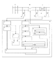
- FIG. 1 is a view showing the configuration of a power system to which a magnetizing inrush current suppression device 30 according to an embodiment of the present invention is applied.
- FIG. 17 is a diagram showing a process flow of this embodiment, and in the following description, process steps in FIG. 17 are also described.
- the excitation inrush current suppression device 30 includes a transformer voltage measurement unit 1, a steady magnetic flux calculation unit 2, an effective shutoff timing calculation unit 3, an effective residual magnetic flux calculation unit 4, a closing phase angle calculation unit 5, and system voltage measurement.
- a section 6, a current phase angle calculation section 7, a closing command output section 8, and a circuit breaker closing operation time calculation section 9 are provided.
- the closing phase angle calculation unit 5 is configured of a first closing phase angle calculation unit 5a and a second closing phase angle calculation unit 5b.
- the system power supply 17 is a system in which an arbitrary single-phase power supply is drawn from a three-phase power supply supplied by a power company, or a system in which a single-phase power supply is drawn from a single-phase power supply system in a facility.
- the single-phase transformer 11 has the system power supply 17 side as the primary side, and the opposite side as the secondary side.
- the single-phase transformer 11 performs voltage value conversion on the single-phase voltage supplied from the system power supply 17 and outputs the voltage to the secondary side.
- the circuit breaker 12 is provided between the system power supply 17 and the single phase transformer 11.
- the single-phase transformer 11 When the system power supply 17 is charged, the single-phase transformer 11 is powered on by the system power supply 17 by turning on the circuit breaker 12. The single-phase transformer 11 is disconnected from the system power supply 17 by opening the circuit breaker 12.
- the voltage detector 14 or the voltage detector 15 which is the first voltage detector installed on the single phase transformer 11 side of the circuit breaker 12 is a measuring device for measuring the voltage on the single phase transformer 11 side. It is.
- the voltage detector 16 which is a second voltage detector installed on the side of the system power supply 17 of the circuit breaker 12 is a measuring device for measuring the voltage on the side of the system power supply 17. Examples of these measuring devices include instrument transformers (VTs).
- the voltage detector 14 or the voltage detector 15 and the voltage detector 16 measure respective voltages.
- the voltage detector 14 or the voltage detector 15 and the voltage detector 16 output the detection value as a detection signal to the excitation inrush current suppression device 30.
- the excitation inrush current suppression device 30 issues a closing command to the main contacts of the circuit breaker 12 according to the information obtained from the detection signal received from each of the voltage detector 14 or the voltage detector 15 and the voltage detector 16. Output. Thus, the circuit breaker 12 is turned on.
- the transformer voltage measurement unit 1 uses the voltage detector 14 or the signal obtained from the voltage detector 15 for the transformer voltage (V1 (t)) on the secondary side of the circuit breaker 12 to measure an instantaneous value, polarity and waveform. measure.
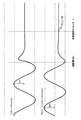
- FIG. 2 shows a single calculated by temporally integrating the transformer voltage (V1 (t)) immediately before and after the single phase transformer 11 is disconnected from the system power supply 17 and the transformer voltage (V1 (t)). It represents the appearance of the magnetic flux ( ⁇ (t)) of the phase transformer 11.
- Steps 1 and 2 When the steady state magnetic flux calculation unit 2 detects the "off" signal of the circuit breaker 12, it integrates the transformer voltage (V1 (t)) measured by the transformer voltage measurement unit 1, and the magnetic flux of the iron core of the transformer 11 Calculate ( ⁇ (t)).
- V1 (t) Vm cos (t) ...
- the effective cutoff timing calculation unit 3 is a timing at which the instantaneous value of the transformer voltage (V1 (t)) measured by the transformer voltage measurement unit 1 when the circuit breaker 12 is opened converges to a zero value or a steady magnetic flux calculation unit
- the timing at which the magnetic flux ( ⁇ (t)) calculated by 2 converges to a constant value is calculated as the effective cutoff timing (t1).
- an arbitrary threshold value is selected.
- the timing at which the instantaneous value of the transformer voltage (V1 (t)) converges to the zero value may be calculated by setting and replacing the value below the threshold value with the zero value.
- Step 4 Among the magnetic fluxes ( ⁇ (t)) calculated by the steady-state magnetic flux calculation unit 2, the effective residual magnetic flux calculation unit 4 calculates the magnetic flux (((t1)) at the effective interruption timing (t1) calculated by the effective shutoff timing calculation unit 3. Calculated as effective residual magnetic flux ( ⁇ r).
- the closing phase angle calculation unit 5 sets the closing phase angle () so that the polarity of the effective residual magnetic flux (rr) calculated by the effective residual magnetic flux calculation unit 4 matches the polarity of the initial excitation magnetic flux when the circuit breaker 12 is closed. Calculate ⁇ close).
- the input phase angle calculation unit 5 includes the first input phase angle calculation unit 5a and the second input phase angle calculation unit 5b, and their functions will be described below.
- Steps 7 and 8 When the polarity of the effective residual magnetic flux ( ⁇ r) is positive, the first closing phase angle calculation unit 5a calculates the closing phase angle ( ⁇ close) such that 0 ° ⁇ close ⁇ 180 °.
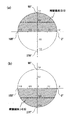
- FIG. 3A illustrates the closing phase angle ( ⁇ close) within a range in which the excitation inrush current can be suppressed.
- the effective residual magnetic flux (rr) is assumed to be 0.5 pu, but the same holds for any value (0 ⁇ r ⁇ 1).
- pu is a unit method (per unit method), and the peak value of voltage and magnetic flux is represented by 1 pu. The same applies to the following description.
- Steps 7 and 9 When the polarity of the effective residual magnetic flux ( ⁇ r) is negative, the second closing phase angle calculation unit 5b calculates the closing phase angle ( ⁇ close) such that 180 ° ⁇ close ⁇ 360 °.
- FIG. 3 (b) illustrates the closing phase angle ( ⁇ close) within a range in which the excitation inrush current can be suppressed, and in this case the effective residual magnetic flux ( ⁇ r) is assumed to be -0.5 pu, but it is arbitrary The same holds true for the value (-1 ⁇ ⁇ r ⁇ 0).
- Steps 5 and 6 Further, the closing phase angle ( ⁇ close) in the case where the effective residual magnetic flux ( ⁇ r) is a zero value is calculated from the angle of the whole range of one cycle.
- the grid voltage measurement unit 6 measures the instantaneous value, the polarity, and the waveform of the grid voltage (V2 (t)) on the grid power supply 17 side of the circuit breaker 12 from the signal obtained from the voltage detector 16.
- Steps 10 and 11 When the current phase angle calculation unit 7 detects the "on" signal of the circuit breaker 12, the system voltage (V2 (t)) at the detection moment is detected by the system voltage (V2 (t)) measured by the system voltage measurement unit 6.
- Steps 12 and 13 The closing command output unit 8 inputs a closing command to the circuit breaker 12 by the current phase angle ( ⁇ 1) calculated by the current phase angle calculating unit 7 and the closing phase angle ( ⁇ close) calculated by the closing phase angle calculating unit 5 Control is completed by outputting. Details of this process will be described later. The function of the circuit breaker closing operation time calculation unit 9 will be described in detail later.
- the voltage drop amount calculation unit 10 is not essential in the present invention, the voltage drop amount calculation unit 10 is provided to measure the suppression rate of the voltage drop amount by the system voltage measurement unit 6. The voltage drop at the time of closing of the circuit breaker 12 can be calculated from the grid voltage.
- the circuit breaker 12 is provided when evaluating the accuracy of the actual value with respect to the input command value by providing the input phase angle actual value calculation unit 20.
- the phase of the system voltage (V2 (tclose)) measured by the system voltage measurement unit 6 is calculated in the transformer voltage generation time (tclose) measured by the transformer voltage measurement unit 1 at the time of turning on the You can also.
- the excitation inrush current suppression device 30 is effective residual flux ( ⁇ r) according to the effective cutoff timing (t1) for residual flux in the iron core of the single phase transformer 11 when the circuit breaker 12 is opened. Is calculated, and the closing phase angle ( ⁇ close) at the closing of the circuit breaker 12 is calculated from the effective residual magnetic flux ((r). Then, the excitation inrush current suppression device 30 can suppress the excitation inrush current by controlling the circuit breaker 12 by the closing phase angle ( ⁇ close).
- the range in which each phase of the residual magnetic flux and the initial excitation magnetic flux can maintain the same polarity is 60.
- the range is 180 degrees, which is advantageous in that control can be performed at a wider range of angles than the prior art.
- the hardware configuration and software configuration can be simplified as compared with the case of the three-phase transformer.
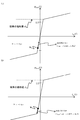
- the closing phase angle calculation unit 5 matches the value of the effective residual magnetic flux (rr) calculated by the effective residual magnetic flux calculation unit 4 with the value of the initial excitation magnetic flux at the next closing of the circuit breaker 12
- the closing phase angle ( ⁇ close) is calculated so that
- FIG. 4 is a diagram showing the configuration of the input phase angle calculation unit 5 according to the first embodiment.
- FIG. 18 is a diagram showing a process flow of this embodiment, and the portion in the frame in FIG. 18 is a characteristic portion in the present embodiment. In the following description, the processing steps in FIG. 18 are also described.
- FIG. 5 illustrates the process content at the time of input phase angle calculation.
- Steps 7 and 8 When the polarity of the effective residual magnetic flux (rr) is positive, the third input phase angle calculation unit 5c shown in FIG. 4 makes an expression such that the value of the effective residual magnetic flux ( ⁇ r) matches the value of the initial excitation magnetic flux.
- the closing phase angle ( ⁇ close) is calculated by (3).
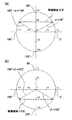
- FIG. 5 (a) illustrates a closing phase angle ( ⁇ close) at which the value of the effective residual flux ( ⁇ r) matches the value of the initial excitation magnetic flux when the polarity of the effective residual flux ( ⁇ r) is positive.
- ⁇ close a closing phase angle
- the effective residual magnetic flux ( ⁇ r) is assumed to be 0.5 pu, but the same holds for any value (0 ⁇ r ⁇ 1).
- Steps 7 and 9 When the polarity of the effective residual magnetic flux (rr) is negative, the fourth closing phase angle calculation unit 5d shown in FIG. 4 makes an expression such that the value of the effective residual magnetic flux ( ⁇ r) matches the value of the initial excitation magnetic flux.
- the closing phase angle ( ⁇ close) is calculated by (4).
- FIG. 5 (b) illustrates a closing phase angle ( ⁇ close) at which the value of the effective residual magnetic flux (rr) matches the value of the initial excitation magnetic flux when the polarity of the effective residual magnetic flux ( ⁇ r) is negative.
- ⁇ close a closing phase angle
- the effective residual magnetic flux ( ⁇ r) is assumed to be ⁇ 0.5 pu, but the same holds for any value ( ⁇ 1 ⁇ ⁇ r ⁇ 0).
- Steps 5 and 6 the process of calculating the closing phase angle ( ⁇ close) when the effective residual magnetic flux ( ⁇ r) has a zero value is determined by equation (5) as two solutions of 0 ° or 180 °.
- the closing phase angle calculation unit 5 it is possible to suppress the decrease in the suppression ratio of the excitation inrush current due to the presence of a range in which the difference between the residual magnetic flux and the initial excitation magnetic flux increases. it can.
- the value of the effective residual magnetic flux ( ⁇ r) calculated by the effective residual magnetic flux calculation unit 4 matches the value of the initial excitation magnetic flux at the next closing of the circuit breaker 12
- the direction of excitation start of the magnetic flux generated from the effective residual flux (rr) selects the closing phase angle ( ⁇ close) in the decreasing direction in absolute value.
- FIG. 6 is a diagram showing the configuration of the closing phase angle calculation unit 5 according to the second embodiment.
- FIG. 19 is a diagram showing a process flow of the present embodiment, and a portion in a frame in FIG. 19 is a characteristic portion in the present embodiment. In the following description, the processing steps in FIG. 19 are also described. 7 and 8 illustrate the appearance of the magnetic flux at the time of closing at the closing phase angle ( ⁇ close).
- FIGS. 7 and 8 show the hysteresis characteristics of the transformer in which the vertical axis represents magnetic flux and the horizontal axis represents current, showing that the current rapidly increases when the magnetic flux reaches the saturation region. There is.
- Steps 7, 8, 8a Of the two solutions of the closing phase angle ( ⁇ close) calculated by the equation (6) from the third closing phase angle calculating unit 5c, the fifth closing phase angle calculating unit 5e illustrated in FIG.
- the direction of the excitation start of the magnetic flux generated starting from) selects the closing phase angle ( ⁇ close) in the decreasing direction in the absolute value.
- FIG. 7A illustrates the appearance of the magnetic flux at the time of closing at the closing phase angle ( ⁇ close) selected in this embodiment among the closing phase angles ( ⁇ close) of the two solutions obtained by the equation (6)
- FIG. 7 (b) illustrates the appearance of the magnetic flux at the time of closing at a closing phase angle ( ⁇ close) not selected in the present embodiment.
- FIG. 9 shows the closing operation time from the generation of the output signal of the closing command by the closing command output unit 8 to the generation of the transformer voltage (V2 (t)).
- V2 (t) the transformer voltage
- the current rapidly increases in consideration of the variation of the closing command value and the closing phase angle of the actual value resulting from the variation of the operation time of the circuit breaker 12 Select the closing phase angle ( ⁇ close) so as to move away from the desired point.
- Steps 7, 9, 9a Of the two solutions of the closing phase angle ( ⁇ close) calculated by the equation (7) from the fourth closing phase angle calculating unit 5d, the sixth closing phase angle calculating unit 5f illustrated in FIG.
- the direction of the excitation start of the magnetic flux generated starting from) selects the closing phase angle ( ⁇ close) in the decreasing direction in the absolute value.
- FIG. 8 (a) illustrates the appearance of the magnetic flux at the time of closing at the closing phase angle ( ⁇ close) selected in this embodiment among the closing phase angles ( ⁇ close) of the two solutions
- FIG. Fig. 11 illustrates the appearance of the magnetic flux at the time of closing at a closing phase angle ( ⁇ close) not selected in the present embodiment.
- Step 9a As shown in FIG. 9, when actually closing the circuit breaker 12 at the closing phase angle ( ⁇ close), the output signal of the closing command is output from the closing command output unit 8 and then the transformer voltage (V2 (t) Since there is a variation in the closing operation time until occurrence of), variations also occur in the closing phase angle ( ⁇ close) of the input command value and the actual measurement value.
- the current rapidly increases in consideration of the variation of the closing command value and the closing phase angle of the actual value resulting from the variation of the operation time of the circuit breaker 12 Select the closing phase angle ( ⁇ close) so as to move away from the desired point.
- Steps 5 and 6 the process of calculating the closing phase angle ( ⁇ close) in the case where the effective residual magnetic flux ( ⁇ r) has a zero value is determined from equation (8) as two solutions of 0 ° or 180 °, but in the present embodiment , Whichever configuration may be selected.
- the variation of the closing command value and the closing phase angle of the actual value which occur from the variation of the closing operation time of the circuit breaker 12 is taken into consideration in actual application. Since the closing phase angle ( ⁇ close) is selected, it can be implemented with higher accuracy.
- the current phase angle ( ⁇ 1) at the time of receiving the “input” signal of the circuit breaker 12 calculated by the current phase angle calculation unit 7 is essential when controlling the circuit breaker 12 with the closing phase angle ( ⁇ close).
- FIG. 10 is a diagram showing a flow from calculation of the current phase angle ( ⁇ 1) when the circuit breaker 12 receives the closing signal in the present embodiment to control of the circuit breaker 12 at the closing phase angle ( ⁇ close). .
- the closing command output point is obtained by adding the closing phase angle ( ⁇ close) calculated by the closing phase angle calculation unit 5 and the closing operation time.
- the closing command delay time is determined by the closing command output point and the current phase angle ( ⁇ 1) at the time when the “on” signal of the circuit breaker 12 is received.
- the circuit breaker 12 takes into consideration by outputting the closing command at the closing command output point after the closing command delay time from the current phase angle ( ⁇ 1) at which the closing signal is received. After the closing operation time, closing is performed at the closing phase angle ( ⁇ close), the "off" state of the circuit breaker 12 changes to the "on” state of the circuit breaker 12, and the control is completed.
- FIG. 11 shows the configuration of the current phase angle calculation unit 7 in the first embodiment.
- FIG. 20 is a diagram showing a processing flow of the present embodiment, and a portion in a frame in FIG. 20 is a characteristic portion in the present embodiment. In the following description, the process steps in FIG.
- FIG. 11 shows that the present phase angle calculation unit 7 shown in FIG. 1 is configured by the present system voltage calculation unit 7a and the present phase angle calculation unit 7b in the present embodiment.
- the current system voltage calculation unit 7a calculates the instantaneous value of the system voltage (V2 (t1)) at the time of receiving the "on" signal of the circuit breaker 12, and the current phase angle calculation unit 7b calculates the system voltage (V2 (V2 (t2)).
- the current phase angle ( ⁇ 1) is calculated from the instantaneous value of t1) and the grid voltage before and after the instantaneous value.
- the present system voltage calculation unit 7a calculates the system voltage (V2 (t1)) measured by the system voltage measurement unit 6 at the time of receiving the "input" signal of the circuit breaker 12.
- the current phase angle calculation unit 7b calculates the grid voltage (V2 (t1)) as a reference point, and the grid voltage (V2 (t1)) and the instantaneous values of the grid voltage before and after the grid voltage (V2 (t1)).
- the current phase angle ( ⁇ 1) is calculated by comparing the magnitudes.
- the grid voltage (V 2 (t)) can take the range of 0 ° ⁇ ⁇ ⁇ 360 ° depending on the timing of the “on” signal reception of the circuit breaker 12.
- FIG. 12 shows that the circuit voltage (V2 (t)) is cut off in the range of 90 ° ⁇ ⁇ 270 ° when the “on” signal of the circuit breaker 12 is received in the range of 270 ° ⁇ ⁇ 90 °. It is explanatory drawing at the time of calculating the present phase angle ((theta) 1) of present system voltage (V2 (t1)) at the time of receiving the "on” signal of unit "12".
- the present phase angle ( ⁇ 1) is obtained by the equation (9) from the system voltage (V2 (t1)) measured by the system voltage measurement unit 6 at the time of receiving the “in” signal of the circuit breaker 12.
- the current phase angle ( ⁇ 1) is calculated using the grid voltage (V2 (t1)) as a reference point, and the grid voltage (V2 (t1)) and the grid voltage (V2 (t1)) one before
- the current phase angle ( ⁇ 1) is calculated by comparing the magnitude of the current value or the next value with the instantaneous value of the grid voltage.
- the number and the position of the value to compare can be determined suitably.
- the present invention provides a method of calculating the current phase angle ( ⁇ 1) based on the magnitude relationship between values before and after the system voltage (V2 (t1)) as a reference point. Thereby, even if there are two phase angles obtained from the system voltage at the time of receiving the "on" signal of the circuit breaker 12, it is possible to prevent an erroneous determination on the determination of the current phase angle.
- FIG. 13 shows the configuration of the current phase angle calculation unit 7 in the second embodiment.
- FIG. 21 is a diagram showing a process flow of the present embodiment, and a portion in a frame in FIG. 21 is a characteristic portion in the present embodiment. In the following description, the processing steps in FIG. 21 are also described.
- the present phase angle calculator 7 shown in FIG. 1 is configured by the pseudo three-phase voltage calculator 7c, the current pseudo three-phase voltage calculator 7d, and the current phase angle calculator 7e in the present embodiment. It shows that it is done.
- Step A, 10, 11e, 11f The pseudo three-phase voltage calculation unit 7 c generates a pseudo three-phase voltage from the grid voltage (V 2 (t)) measured by the grid voltage measurement unit 6, and the pseudo three-phase voltage calculation unit 7 d The instantaneous value of the pseudo three-phase voltage at the time of receiving the “I” signal is calculated, and the current phase angle calculation unit 7e calculates the current phase angle ( ⁇ 1) from the instantaneous value of the pseudo three phase voltage using the pseudo three phase voltage. .
- FIG. 14 shows a waveform in which the system voltage (V2 (t)) measured by the system voltage measurement unit 6 includes harmonics, and a pseudo three-phase voltage is generated from the system voltage (V2 (t)).
- Step A The generation of the other two phases V3 ( ⁇ ) and V4 ( ⁇ ) shown in FIG. 14A is the zero crossing point at the rising of the system voltage (V2 (t)) measured by the system voltage measurement unit 6. Is simulated from the peak value of one cycle before by the equations (10) and (11) for one cycle from the zero crossing point, and repeatedly generated for each zero crossing point.
- V3 ( ⁇ ) Vmsin ( ⁇ + 240 °) ( ⁇ : 0 ° ⁇ ⁇ ⁇ 360 °) Equation (10)
- V4 ( ⁇ ) Vmsin ( ⁇ + 120 °) ( ⁇ : 0 ° ⁇ ⁇ ⁇ 360 °) (11)
- Step A About generation of V5 ((theta)) shown in FIG.14 (b), system voltage (V2 (t)) is simulation-generated by Formula (12) from Formula (10) and Formula (11).
- V5 ( ⁇ ) Vmsin ( ⁇ ) ( ⁇ : 0 ° ⁇ ⁇ ⁇ 360 °) (12)
- Steps 10, 11e, 11f If the system voltage (V2 (t)) measured by the system voltage measurement unit 6 includes harmonics, the system voltage (V2 (t)) may be miscalculated if it is used to calculate the current phase angle ( ⁇ 1). Therefore, as a countermeasure against this, the current phase angle ( ⁇ 1) of the pseudo three-phase voltage at the time of receiving the “on” signal of the circuit breaker 12 is calculated by the equation (13) using the pseudo three-phase voltage.
- the grid voltage (V5 (t1)) at the time of receiving the “in” signal of the circuit breaker 12 is calculated as the reference point, and the grid voltage before and after the grid voltage (V5 (t1))
- the present phase angle ( ⁇ 1) may be calculated by comparing the magnitude with the instantaneous value of.
- the number and position of the value to compare can be decided suitably.
- the grid voltage (V5 (t1)) at the time of receiving the “in” signal of the circuit breaker 12 is calculated as the reference point, and the grid voltage (V5 (t1)) and the grid voltage
- the present phase angle ( ⁇ 1) may be calculated by comparing the magnitude of the value immediately before (V5 (t1)) or the instantaneous value of the system voltage with the value immediately after it. Also in this case, in comparison of the values before and after the system voltage (V5 (t1)) serving as the reference at the time of calculation of the current phase angle ( ⁇ 1), the number and position of values to be compared can be determined appropriately.
- the current phase angle calculated by the current phase angle calculation unit 7e using the pseudo three-phase voltage calculated by the pseudo three-phase voltage calculation unit 7c. ( ⁇ 1) is calculated.
- the current phase angle is calculated from the instantaneous value of the three-phase voltage to be measured, and harmonic components are included. Even if the current phase angle can be calculated, if the same processing is performed in the case of a single-phase transformer, the current phase angle is calculated by this effect if a harmonic component is included. It can happen that the accuracy of However, the current phase angle can be accurately calculated by calculating the current phase angle by the method of this embodiment, instead of using the single phase voltage as it is for calculating the current phase angle.
- the circuit breaker closing operation time calculation unit 9 includes a transformer voltage determination unit 9a and a transformer voltage continuity determination unit 9b.
- FIG. 22 is a diagram showing a process flow of the present embodiment, and the portion in the frame in FIG. 22 is a characteristic portion in the present embodiment. In the following description, processing steps in FIG. 22 are also described.
- Steps X1, X2, X3, X4 The circuit breaker closing operation time calculation unit 9 measures the transformer voltage (V1 (t)) measured by the transformer voltage measuring unit 1 from the closing instruction output time, which is the timing at which the closing instruction is output by the closing instruction output unit 8. The time until the transformer voltage generation point, which is the starting point when the absolute value of V exceeds the input determination threshold continuously for an arbitrary period, is calculated.
- FIG. 15 illustrates the relationship between the value obtained by sampling the value of the transformer voltage (V1 (t)) before and after transformer charging at a constant sampling interval (ts) and the input judgment threshold ⁇ ⁇ . is there.
- the transformer voltage exceeds the input judgment threshold due to external factors such as noise generation ( ⁇ ⁇ V1 (t) or V1 (t) ⁇ ⁇ ).
- the transformer voltage may fall below the closing judgment threshold value from the relationship between the sampling period and the voltage waveform ( ⁇ ⁇ V1 (t) ⁇ ).
- Step X1 The transformer voltage judging unit 9a misjudges that the transformer voltage is generated when the transformer voltage exceeds the input judgment threshold due to an external factor before the transformer load, or the transformer after the transformer load
- the voltage is acquired at sampling intervals of every 3 degrees with respect to the input voltage waveform, and The reference point when three points out of the total of four sampling voltages of the voltage, the voltage from the reference point to two samplings before and the sampling voltage one ahead of the reference point It is judged that the transformer voltage generation in That is, the transformer voltage is acquired at a plurality of points in a fixed sampling cycle, and it is determined whether the voltage at the reference point exceeds the input determination threshold value, thereby determining whether or not the transformer voltage is generated at the reference point.
- FIG. 16 illustrates the change in transformer voltage and the time from the input command output time (tcx) to the transformer voltage generation time (tclose).
- (a) input command output, (b) noise generation, (c) presence or absence of transformer voltage, (d) continuity evaluation, (e) presence or absence of transformer voltage (after continuity evaluation) are shown. .
- a point at which a transformer voltage is generated at the time of noise generation after (b) a generation of a noise generation is (1) a temporary transformer voltage generation point (tclose0), but (d) During the transformer voltage continuity judgment time ⁇ in which the continuity evaluation represents 1 time, (c) no transformer voltage is generated as indicated by the presence or absence of the transformer voltage. (E) It is shown that the presence or absence of transformer voltage (after continuity evaluation) remains 0.
- Step X2 The transformer voltage continuity determination unit 9b determines a temporary transformer voltage generation time (tclose0) from the voltage generation presence or absence determined by the transformer voltage determination unit 9a, and a transformer is generated from this temporary transformer voltage generation time (tclose0). Assuming that voltage continuity determination time ⁇ is one cycle of the voltage waveform, and all determination results of transformer voltage determination unit 9a indicate that there is a transformer voltage, a temporary transformer voltage generation time point (tclose0) is generated as a transformer voltage generation Calculated as time point (tclose). That is, when it is determined that the transformer voltage is continuously generated for a predetermined time, the time when it is determined that the transformer voltage is generated for the first time is calculated as the transformer voltage generation time.
- Step X4 The closing operation time (tcb) is calculated by equation (14) from the closing command output time (tcx) and the transformer voltage generation time (tclose).
- the timing when the closing command is output from the closing command output unit 8 is set as the closing command output time, and the absolute value of the transformer voltage measured by the transformer voltage measuring unit 1 is continuously determined to be open for an arbitrary period.
- the circuit breaker closing operation time can be determined from the closing command output time point and the transformer voltage generation time point when the transformer voltage generation time point is taken as the starting point from the first timing exceeding the threshold value. This is the function of the operation time calculator 9.
- transformer voltage determination unit 9a acquires voltages at sampling intervals of 3 degrees with respect to the input voltage waveform, and generates the voltage of the reference point and the voltage of two samples before the reference point. Of the total of four sampling voltages with the sampling voltage one point ahead of the reference point, three points are used as the judgment criteria for the closing judgment threshold, but the sampling cycle, the closing judgment threshold, and the number of samplings used for judgment It can be changed as appropriate, and can be configured to change the judgment criteria manually or automatically.
- transformer voltage continuity determination unit 9b uses the continuity for one cycle of the voltage waveform as the determination criterion, the period used for the determination can be appropriately changed, and the determination criterion can be manually or automatically. The configuration can be changed.
- the threshold used as the determination reference can be set high.
- the possibility of misjudgment is extremely low.
- the single-phase transformer is different from the case of the three-phase transformer, and the method of the three-phase transformer can not be applied as it is.
- the closing operation time calculation unit 9 uses the transformer voltage generation time point determined by the transformer voltage determination unit 9a and the transformer voltage continuity determination unit 9b to generate noise and the like. Even if there is a cause, it is possible to prevent an erroneous determination of the determination of the circuit breaker closing operation time, and it is possible to obtain the closing operation time of the single phase transformer with high accuracy.
- the present invention can suppress the excitation inrush current of a single phase transformer by a method of calculating residual magnetic flux, and can calculate the current phase angle even if noise or harmonics are included in the single phase voltage.
- the present invention can be widely used as a magnetizing inrush current suppressor capable of accurately determining the breaker closing operation time.
Landscapes
- Engineering & Computer Science (AREA)
- Power Engineering (AREA)
- Driving Mechanisms And Operating Circuits Of Arc-Extinguishing High-Tension Switches (AREA)
- Protection Of Transformers (AREA)
- Keying Circuit Devices (AREA)
Abstract
【課題】残留磁束の算出方法を明示して、単相変圧器の励磁突入電流抑制を具体的に実現することを可能にするとともに、単相電圧にノイズや高調波が含まれていても、現在位相角の算出を正確に行うことができ、遮断器投入動作時間の判定も正確に行うことが可能な励磁突入電流抑制装置を提供する。 【解決手段】励磁突入電流抑制装置30は、変圧器電圧計測部1と、定常磁束算出部2と、実効遮断タイミング算出部3と、実効残留磁束算出部4と、投入位相角算出部5と、系統電圧計測部6と、現在位相角算出部7と、投入指令出力部8と、遮断器投入動作時間算出部9とを備えている。
Description
本発明は、単相交流電圧の電源系統と単相変圧器との接続を開閉する遮断器を投入する際に生じる励磁突入電流を抑制するための励磁突入電流抑制装置に関する。
変圧器再課電に伴う励磁突入電流による障害を排除するための装置として、励磁突入電流抑制装置が知られている。三相用変圧器についての励磁突入電流抑制装置に関する発明が、特許文献1において開示されている。これは、三相変圧器、および系統電源間に接続された遮断器を制御する仕組みを有する励磁突入電流抑制装置であり、「電圧計測部」と「実効遮断タイミング算出部」と「鉄心磁束算出部」と「実効残留磁束算出部」と「投入位相角算出部」と「投入位相角制御部」を備え、必要に応じて「遮断時間算出部」と「見かけ残留磁束算出部」と「投入動作時間算出部」と「投入位相角実績値算出部」と「瞬時電圧低下量算出部」を備えた構造となっている。この発明は、残留磁束の測定方法に大きな特徴があり、その残留磁束から算出された投入位相角を用いての励磁突入電流の抑制を行っている点において大きな効果がある。ただし、この発明は、三相変圧器用のアルゴリズムで構成されており、単相変圧器へそのまま適用することはできない。
一方、単相変圧器への適用を目的とした励磁突入電流抑制装置に関する発明が、特許文献2において開示されている。これは、低圧の単相変圧器への電源投入時に突入電流の発生を防止する単相変圧器用突入電流防止装置に関するものであり、「変圧器の一次側電源回路上に接続した電源監視回路が電源の投入・遮断を検出するとともに、変圧器の一次側電源回路上に接続した位相検出回路が、電源遮断時の電源電圧の位相角度を検出する。また、変圧器の一次側電源回路上に電源の遮断時にオフされるスイッチング素子を接続しておく。それにより、変圧器への電源が遮断されたことが検出されると、電源遮断時の電源電圧の位相角度が記憶され、次いで、変圧器へ電源が再投入されたことが検出されると、記憶手段に記憶されている前回遮断時の電源電圧位相角度にもとづき突入電流を小さくする電源投入タイミングを求め、そのタイミングに達した時点で前記スイッチング素子をオンして電源の再投入をする。それにより、電源の再投入は、常に突入電流を少なくするタイミングで行われる。」ことが開示されている。
しかし、特許文献2に記載のものは、特許文献1に記載のもののように、残留磁束の算出方法が具体的に示されておらず、実施可能性の点で問題がある。また、「変圧器の一次側電源回路上に電源の遮断時にオフされるスイッチング素子を接続しておく。」とあり、「低圧の単相変圧器」を対象としていることから、高圧、または容量の大きい変圧器を適用対象としていない。これは、一次側電源回路上に接続されるスイッチング素子の仕様の制限や実用に向けた設置や保守などの取扱いが困難になることからも推測でき、スイッチング素子を用いていることから、半導体を材料にしていることが前提となっていると考えられる。
また、特許文献3に記載されている突入電流防止回路は、電源入力トランス(単相)へ給電するAC電源ラインに挿入された電源投入制御回路と、投入遮断検出回路と位相検出回路、および位相記憶回路により突入電流が生じない条件時に投入制御回路とこれを作動させる比較回路により突入電流を防止する回路である。しかし、残留磁束の算出方法が具体的に示されておらず、また、高圧、または容量の大きい変圧器を適用対象としていない。その他、特許文献4には、位相角制御で励磁突入電流を抑制する装置が記載されており、三相交流を単相交流に変換する変圧器の、スコット結線、ウッドブリッジ結線変圧器、または変形ウッドブリッジ結線変圧器を制御対象としている。この装置において、抑制対象は単相交流側であり、M相とT相それぞれに遮断器がある構成となっている。しかし、この特許文献においても、残留磁束の算出方法が具体的に示されていない。
このように、単相変圧器への適用を目的とした励磁突入電流抑制装置については、残留磁束の算出方法が具体的に明示された先行技術文献は存在しておらず、機械的な構造を持つために、定期的な保守・更新が必要となる投入抵抗付遮断器等が存在するに留まっている。また、単相変圧器への適用を目的とする場合には、単相電圧の性質上、遮断器の「入」信号受信時の系統電圧から求められる位相角が2解存在することによって現在位相角の判定を誤判定する可能性がある。また、電圧に高調波が含まれている場合には、現在位相角算出の精度が下がるという問題点もある。さらに、単相電圧の場合、ノイズの影響によって遮断器投入動作時間の算出において、単相電圧の性質上、遮断器投入動作時間の判定を誤判定してしまう可能性もある。従って、三相変圧器の技術をそのまま単相の技術に適用することはできない。
本発明は、このような事情を考慮してなされたもので、残留磁束の算出方法を明示して、単相変圧器の励磁突入電流抑制を具体的に実現することを可能にするとともに、単相電圧にノイズや高調波が含まれていても、現在位相角の算出を正確に行うことができ、遮断器投入動作時間の判定も正確に行うことが可能な励磁突入電流抑制装置を提供することを目的とする。
以上の課題を解決するために、本発明の励磁突入電流抑制装置は、単相交流電圧の電源系統と単相変圧器との接続を開閉する遮断器を投入する際に生じる励磁突入電流を抑制する励磁突入電流抑制装置であって、前記遮断器の前記単相変圧器側に設置された第1の電圧検出器の前記単相交流電圧である変圧器電圧を計測する変圧器電圧計測部と、前記遮断器の系統電源側に設置された第2の電圧検出器の前記単相交流電圧である系統電圧を計測する系統電圧計測部と、前記変圧器電圧計測部で計測された前記変圧器電圧により前記単相変圧器の鉄心内部の定常磁束を算出する定常磁束算出部と、前記変圧器電圧計測部により計測された前記変圧器電圧の瞬時値がゼロ値に収束したタイミング、または前記定常磁束算出部により算出された前記定常磁束の値が一定値に達するタイミングを実効遮断タイミングとして算出する実効遮断タイミング算出部と、前記実効遮断タイミングにおける前記定常磁束算出部により算出された前記定常磁束の値を実効残留磁束として算出する実効残留磁束算出部と、前記実効残留磁束算出部で算出された前記実効残留磁束の極性と前記遮断器の投入時の初期励磁磁束の極性とを一致させるように投入位相角を算出する投入位相角算出部と、前記系統電圧計測部で計測された前記系統電圧から現在位相角を算出する現在位相角算出部と、前記現在位相角算出部で算出された前記現在位相角、および前記投入位相角算出部で算出された前記投入位相角に基づいて前記遮断器が投入されるように、前記遮断器へ投入指令を出力する投入指令出力部を備えていることを特徴とする。
前記の構成とすることにより、単相変圧器の励磁突入電流を抑制するために必須である残留磁束を算出する手法を明示して、単相変圧器の励磁突入電流抑制を具体的に実現でき、実用的な励磁突入電流抑制装置とすることができる。
本発明の励磁突入電流抑制装置においては、前記投入位相角算出部は、前記実効残留磁束算出部により算出された前記実効残留磁束の値と、前記遮断器の投入時の前記初期励磁磁束の値とが一致するように、前記投入位相角を算出するものとすることができる。
投入位相角算出部を前記の構成とすることにより、残留磁束と初期励磁磁束との差が大きくなる範囲があることによる、励磁突入電流の抑制率の低下を抑制することができる。
本発明の励磁突入電流抑制装置においては、前記投入位相角算出部は、前記実効残留磁束算出部により算出された前記実効残留磁束の値と、前記遮断器の投入時の前記初期励磁磁束の値とが一致する前記投入位相角の2解のうち、前記実効残留磁束を起点として生成される磁束の励磁開始の方向が、絶対値において減少する方向の前記投入位相角を選択するものとすることができる。
投入位相角算出部を前記の構成とすることにより、遮断器投入動作時間が、考慮した値よりもばらつきが大きいときに精度が下がることを抑制することができる。
本発明の励磁突入電流抑制装置においては、前記現在位相角算出部は、前記遮断器の「入」信号受信時の前記系統電圧の瞬時値を算出し、前記瞬時値と前記瞬時値の前後のタイミングにおける前記系統電圧から前記現在位相角を算出するものとすることができる。
現在位相角算出部を前記の構成とすることにより、遮断器の「入」信号受信時の系統電圧から求められる位相角が2解存在しても、現在位相角の判定についての誤判定を防止することができる。
本発明の励磁突入電流抑制装置においては、前記現在位相角算出部は、前記系統電圧から擬似三相電圧を生成し、前記遮断器の「入」信号受信時の前記擬似三相電圧の瞬時値から前記現在位相角を算出するものとすることができる。
現在位相角算出部を前記の構成とすることにより、単相電圧に高調波が含まれている場合であっても、現在位相角算出を精度良く行うことができる。
本発明の励磁突入電流抑制装置においては、前記投入指令出力部より前記投入指令が出力されたタイミングを投入指令出力時点とし、前記変圧器電圧計測部により計測された前記変圧器電圧の絶対値が任意の期間連続して投入判断しきい値を超えた最初のタイミングを起点として、その起点を変圧器電圧発生時点とした際の、前記投入指令出力時点と前記変圧器電圧発生時点とから遮断器投入動作時間を算出する遮断器投入動作時間算出部を備えている構成とすることができる。
前記の構成を有する遮断器投入動作時間算出部を備えていることにより、ノイズの発生等の外的要因があっても、遮断器投入動作時間の判定についての誤判定を防止することができる。
本発明によると、残留磁束を算出する手法により、単相変圧器の励磁突入電流の抑制が可能であり、単相電圧にノイズや高調波が含まれている場合であっても、現在位相角の算出と遮断器投入動作時間の判定を正確に行うことが可能な励磁突入電流抑制装置を実現することができる。
以下に、本発明の励磁突入電流抑制装置を、その実施形態に基づいて説明する。
本発明の実施形態に係る励磁突入電流抑制装置30について、図1、図2、図3を用いて説明する。
本発明の実施形態に係る励磁突入電流抑制装置30について、図1、図2、図3を用いて説明する。
図1は、本発明の実施形態に係る励磁突入電流抑制装置30が適用された電力システムの構成を示す図である。図17は本実施形態の処理フローを示す図であり、以下の説明において、図17における処理ステップを併記している。
励磁突入電流抑制装置30は、変圧器電圧計測部1と、定常磁束算出部2と、実効遮断タイミング算出部3と、実効残留磁束算出部4と、投入位相角算出部5と、系統電圧計測部6と、現在位相角算出部7と、投入指令出力部8と、遮断器投入動作時間算出部9とを備えている。投入位相角算出部5は、第1の投入位相角算出部5aと、第2の投入位相角算出部5bとによって構成されている。
系統電源17は、電力会社が供給している三相電源から任意の単相電源を引き込んだシステム、または設備内における単相電源系統から単相電源を引き込んだシステムである。
単相変圧器11は、系統電源17側を1次側とし、その逆側を2次側とする。単相変圧器11は、系統電源17から供給される単相電圧を電圧値変換して二次側に出力する。
遮断器12は、系統電源17と単相変圧器11との間に設けられている。系統電源17が充電されている場合、遮断器12が投入されることにより、単相変圧器11は、系統電源17によって電源投入される。遮断器12が開放されることにより、単相変圧器11は系統電源17から遮断される。
遮断器12の単相変圧器11側に設置された第1の電圧検出器である電圧検出器14、または電圧検出器15は、単相変圧器11側の電圧を計測するための計測用機器である。また、遮断器12の系統電源17側に設置された第2の電圧検出器である電圧検出器16は、系統電源17側の電圧を計測するための計測用機器である。これら計測用機器としては、例えば、計器用変圧器(VT)などがある。電圧検出器14、または電圧検出器15、および電圧検出器16は、それぞれの電圧を計測する。電圧検出器14、または電圧検出器15、および電圧検出器16は、検出値を検出信号として、励磁突入電流抑制装置30に出力する。
励磁突入電流抑制装置30は、電圧検出器14、または電圧検出器15、および電圧検出器16のそれぞれから受信した検出信号から得られた情報によって、遮断器12の主接点に対して投入指令を出力する。これにより、遮断器12は投入される。
変圧器電圧計測部1は、遮断器12の二次側の変圧器電圧(V1(t))について、電圧検出器14、または電圧検出器15から得られる信号により、瞬時値、極性および波形を計測する。
図2は、単相変圧器11が系統電源17から解列される直前と直後の変圧器電圧(V1(t))と、変圧器電圧(V1(t))を時間積分して算出した単相変圧器11の磁束(Φ(t))の様相を表したものである。
(ステップ1、2)
定常磁束算出部2は、遮断器12の「切」信号を検出すると、変圧器電圧計測部1により計測された変圧器電圧(V1(t))を積分して、変圧器11の鉄心の磁束(Φ(t))を算出する。
定常磁束算出部2は、遮断器12の「切」信号を検出すると、変圧器電圧計測部1により計測された変圧器電圧(V1(t))を積分して、変圧器11の鉄心の磁束(Φ(t))を算出する。
ここで、変圧器電圧(V1(t))と磁束(Φ(t))との関係は、式(1)と式(2)の関係性が成り立つ。
V1(t)=Vmcos(t) …式(1)
Φ(t)=∫V1(t)dt=Φmsin(t) …式(2)
(ステップ3)
実効遮断タイミング算出部3は、遮断器12の開放時における変圧器電圧計測部1により計測された変圧器電圧(V1(t))の瞬時値がゼロ値に収束したタイミング、または定常磁束算出部2により算出された磁束(Φ(t))が一定値に収束するタイミングを実効遮断タイミング(t1)として算出する。また、遮断器12の開放時における変圧器電圧計測部1により計測された変圧器電圧(V1(t))の瞬時値が誘導などによりゼロ値に収束しない場合には、任意のしきい値を設定し、そのしきい値以下となる値をゼロ値に置き換えることによって、変圧器電圧(V1(t))の瞬時値がゼロ値に収束したタイミングを算出する構成であってもよい。
実効遮断タイミング算出部3は、遮断器12の開放時における変圧器電圧計測部1により計測された変圧器電圧(V1(t))の瞬時値がゼロ値に収束したタイミング、または定常磁束算出部2により算出された磁束(Φ(t))が一定値に収束するタイミングを実効遮断タイミング(t1)として算出する。また、遮断器12の開放時における変圧器電圧計測部1により計測された変圧器電圧(V1(t))の瞬時値が誘導などによりゼロ値に収束しない場合には、任意のしきい値を設定し、そのしきい値以下となる値をゼロ値に置き換えることによって、変圧器電圧(V1(t))の瞬時値がゼロ値に収束したタイミングを算出する構成であってもよい。
(ステップ4)
実効残留磁束算出部4は、定常磁束算出部2により算出した磁束(Φ(t))のうち、実効遮断タイミング算出部3により算出した実効遮断タイミング(t1)における磁束(Φ(t1))を実効残留磁束(Φr)として算出する。
実効残留磁束算出部4は、定常磁束算出部2により算出した磁束(Φ(t))のうち、実効遮断タイミング算出部3により算出した実効遮断タイミング(t1)における磁束(Φ(t1))を実効残留磁束(Φr)として算出する。
投入位相角算出部5は、実効残留磁束算出部4により算出された実効残留磁束(Φr)の極性と、遮断器12の投入時における初期励磁磁束の極性とを一致させるように投入位相角(θclose)を算出する。
特に、本実施形態に係る投入位相角算出部5は、第1の投入位相角算出部5aと、第2の投入位相角算出部5bとを備えており、それぞれの機能について以下に説明する。
(ステップ7、8)
第1の投入位相角算出部5aは、実効残留磁束(Φr)の極性が正の場合に、0°<θclose<180°の範囲となるように投入位相角(θclose)を算出する。図3(a)は、励磁突入電流を抑制できる範囲の投入位相角(θclose)を図示したものである。ここでは実効残留磁束(Φr)が0.5puと仮定しているが、任意の値(0<Φr≦1)においても成立する。
第1の投入位相角算出部5aは、実効残留磁束(Φr)の極性が正の場合に、0°<θclose<180°の範囲となるように投入位相角(θclose)を算出する。図3(a)は、励磁突入電流を抑制できる範囲の投入位相角(θclose)を図示したものである。ここでは実効残留磁束(Φr)が0.5puと仮定しているが、任意の値(0<Φr≦1)においても成立する。
ここでの「pu」とは、単位法(per unit法)のことであり、電圧と磁束の波高値を1puで表すものとする。これは、以下の説明においても同様である。
(ステップ7、9)
第2の投入位相角算出部5bは、実効残留磁束(Φr)の極性が負の場合に、180°<θclose<360°の範囲となるように投入位相角(θclose)を算出する。図3(b)は、励磁突入電流を抑制できる範囲の投入位相角(θclose)を図示したものであり、ここでは実効残留磁束(Φr)が-0.5puと仮定しているが、任意の値(-1≦Φr<0)においても成立する。
第2の投入位相角算出部5bは、実効残留磁束(Φr)の極性が負の場合に、180°<θclose<360°の範囲となるように投入位相角(θclose)を算出する。図3(b)は、励磁突入電流を抑制できる範囲の投入位相角(θclose)を図示したものであり、ここでは実効残留磁束(Φr)が-0.5puと仮定しているが、任意の値(-1≦Φr<0)においても成立する。
(ステップ5、6)
また、実効残留磁束(Φr)がゼロ値の場合の投入位相角(θclose)は、1周期の全範囲の角度から算出する構成とする。
また、実効残留磁束(Φr)がゼロ値の場合の投入位相角(θclose)は、1周期の全範囲の角度から算出する構成とする。
系統電圧計測部6は、遮断器12の系統電源17側の系統電圧(V2(t))について、電圧検出器16から得られる信号により、瞬時値、極性および波形を計測する。
(ステップ10、11)
現在位相角算出部7は、遮断器12の「入」信号を検出すると、系統電圧計測部6により計測された系統電圧(V2(t))により、検出瞬時の系統電圧(V2(t))の現在位相角(θ1)を算出する。
現在位相角算出部7は、遮断器12の「入」信号を検出すると、系統電圧計測部6により計測された系統電圧(V2(t))により、検出瞬時の系統電圧(V2(t))の現在位相角(θ1)を算出する。
(ステップ12、13)
投入指令出力部8は、現在位相角算出部7により算出された現在位相角(θ1)と、投入位相角算出部5により算出された投入位相角(θclose)により、遮断器12に投入指令を出力することで制御完了となる。この処理の詳細については、後に詳述する。また、遮断器投入動作時間算出部9の機能については、後に詳述する。
投入指令出力部8は、現在位相角算出部7により算出された現在位相角(θ1)と、投入位相角算出部5により算出された投入位相角(θclose)により、遮断器12に投入指令を出力することで制御完了となる。この処理の詳細については、後に詳述する。また、遮断器投入動作時間算出部9の機能については、後に詳述する。
なお、電圧低下量算出部10は、本発明において必須ではないが、電圧低下量算出部10を設けることによって、電圧低下量の抑制率を評価する際に、系統電圧計測部6により計測された系統電圧から遮断器12の投入時の電圧低下を算出する構成とすることができる。
また、投入位相角実績値算出部20は、本発明において必須ではないが、投入位相角実績値算出部20を設けることによって、投入指令値に対する実績値の精度を評価する際に、遮断器12の投入時の変圧器電圧計測部1により計測された変圧器電圧発生時間(tclose)において、系統電圧計測部6により計測された系統電圧(V2(tclose))の位相を算出する構成とすることもできる。
このように、本実施形態に係る励磁突入電流抑制装置30は、遮断器12の開放時における単相変圧器11の鉄心内の残留磁束について、実効遮断タイミング(t1)により実効残留磁束(Φr)を算出し、その実効残留磁束(Φr)により遮断器12の投入時における投入位相角(θclose)を算出する。そして、励磁突入電流抑制装置30は、投入位相角(θclose)により遮断器12を制御することによって、励磁突入電流を抑制することができる。
前記の手法を、三相変圧器を対象とした先行技術文献における手法と比較すると、三相変圧器の場合には、残留磁束と初期励磁磁束の各相同士が同極性を維持できる範囲は60度であるのに対して、本発明においては、その範囲は180度であり、従来技術よりも広い範囲の角度において制御が可能である点において有利である。また、三相変圧器の場合よりも、ハードウエアの構成とソフトウエアの構成などを簡略化できる。
次に、投入位相角算出部5についての第一実施形態について説明する。
本実施形態に係る投入位相角算出部5は、実効残留磁束算出部4により算出された実効残留磁束(Φr)の値と、次回の遮断器12の投入時における初期励磁磁束の値とを一致させるように投入位相角(θclose)を算出する。
本実施形態に係る投入位相角算出部5は、実効残留磁束算出部4により算出された実効残留磁束(Φr)の値と、次回の遮断器12の投入時における初期励磁磁束の値とを一致させるように投入位相角(θclose)を算出する。
図4は、第一実施形態に係る投入位相角算出部5の構成を示す図である。図18は、この実施形態の処理フローを示す図であり、図18における枠内の部分が、本実施形態において特徴的な部分である。以下の説明において、図18における処理ステップを併記している。また、図5は、投入位相角算出時の処理内容を図示したものである。
(ステップ7、8)
図4に示す第3の投入位相角算出部5cは、実効残留磁束(Φr)の極性が正の場合に、実効残留磁束(Φr)の値と初期励磁磁束の値を一致させるように、式(3)により投入位相角(θclose)を算出する。
図4に示す第3の投入位相角算出部5cは、実効残留磁束(Φr)の極性が正の場合に、実効残留磁束(Φr)の値と初期励磁磁束の値を一致させるように、式(3)により投入位相角(θclose)を算出する。
θclose=sin-1(Φr)=α、180-α
(但し、Φr>0、α:0°<α<180°) …式(3)
(但し、Φr>0、α:0°<α<180°) …式(3)
図5(a)は、実効残留磁束(Φr)の極性が正の場合に、実効残留磁束(Φr)の値と初期励磁磁束の値が一致する投入位相角(θclose)を図示したものであり、投入位相角(θclose)は2解存在する。ここでは、実効残留磁束(Φr)が0.5puと仮定しているが、任意の値(0<Φr≦1)においても成立する。
(ステップ7、9)
図4に示す第4の投入位相角算出部5dは、実効残留磁束(Φr)の極性が負の場合に、実効残留磁束(Φr)の値と初期励磁磁束の値を一致させるように、式(4)により投入位相角(θclose)を算出する。
図4に示す第4の投入位相角算出部5dは、実効残留磁束(Φr)の極性が負の場合に、実効残留磁束(Φr)の値と初期励磁磁束の値を一致させるように、式(4)により投入位相角(θclose)を算出する。
θclose=sin-1(Φr)=β、180-β
(但し、Φr<0、β:180°<β<360°) …式(4)
(但し、Φr<0、β:180°<β<360°) …式(4)
図5(b)は、実効残留磁束(Φr)の極性が負の場合に、実効残留磁束(Φr)の値と初期励磁磁束の値が一致する投入位相角(θclose)を図示したものであり、投入位相角(θclose)は2解存在する。ここでは、実効残留磁束(Φr)が-0.5puと仮定しているが、任意の値(-1≦Φr<0)においても成立する。
(ステップ5、6)
また、実効残留磁束(Φr)がゼロ値の場合の投入位相角(θclose)を算出する処理は、式(5)により、0°または180°の2解に決定される。
また、実効残留磁束(Φr)がゼロ値の場合の投入位相角(θclose)を算出する処理は、式(5)により、0°または180°の2解に決定される。
θclose=sin-1(Φr=0)=0°、180° …式(5)
以上説明した、投入位相角算出部5についての第一実施形態によると、残留磁束と初期励磁磁束との差が大きくなる範囲があることによる、励磁突入電流の抑制率の低下を抑制することができる。
次に、投入位相角算出部5についての第二実施形態について説明する。
本実施形態に係る投入位相角算出部5は、実効残留磁束算出部4により算出された実効残留磁束(Φr)の値と、次回の遮断器12の投入時における初期励磁磁束の値とが一致する投入位相角(θclose)の2解のうち、実効残留磁束(Φr)を起点として生成される磁束の励磁開始の方向が、絶対値において減少する方向の投入位相角(θclose)を選択する。
本実施形態に係る投入位相角算出部5は、実効残留磁束算出部4により算出された実効残留磁束(Φr)の値と、次回の遮断器12の投入時における初期励磁磁束の値とが一致する投入位相角(θclose)の2解のうち、実効残留磁束(Φr)を起点として生成される磁束の励磁開始の方向が、絶対値において減少する方向の投入位相角(θclose)を選択する。
図6は、第二実施形態に係る投入位相角算出部5の構成を示す図である。図19は本実施形態の処理フローを示す図であり、図19における枠内の部分が、本実施形態において特徴的な部分である。以下の説明において、図19における処理ステップを併記している。また、図7、図8は、投入位相角(θclose)で投入した際の磁束の様相について図示したものである。
図7および図8は、縦軸を磁束とし、横軸を電流で表した変圧器のヒステリシス特性であり、磁束が飽和域に達すると電流が急激に増大する特性を持っていることを示している。
(ステップ7、8、8a)
図6に示す第5の投入位相角算出部5eは、第3の投入位相角算出部5cから式(6)により算出される投入位相角(θclose)の2解のうち、実効残留磁束(Φr)を起点として生成される磁束の励磁開始の方向が、絶対値において減少する方向の投入位相角(θclose)を選択する。
図6に示す第5の投入位相角算出部5eは、第3の投入位相角算出部5cから式(6)により算出される投入位相角(θclose)の2解のうち、実効残留磁束(Φr)を起点として生成される磁束の励磁開始の方向が、絶対値において減少する方向の投入位相角(θclose)を選択する。
θclose=sin-1(Φr)=α、180-α
(但し、Φr>0、α:0°<α<180°) …式(6)
(但し、Φr>0、α:0°<α<180°) …式(6)
図7(a)は、式(6)によって得られる2解の投入位相角(θclose)のうち、本実施形態で選択する投入位相角(θclose)で投入した際の磁束の様相を図示したものであり、図7(b)は、本実施形態で選択しない投入位相角(θclose)で投入した際の磁束の様相を図示したものである。
(ステップ6)
図9は、投入指令出力部8により投入指令の出力信号を発してから変圧器電圧(V2(t))が発生するまでの投入動作時間を示す。図9に示すように、実際に投入位相角(θclose)で遮断器12を投入する際には、投入指令出力部8により投入指令の出力信号が出力されてから変圧器電圧(V2(t))が発生するまでの投入動作時間にばらつきがあるため、投入指令値と実測値の投入位相角(θclose)についてもばらつきが生じる。
図9は、投入指令出力部8により投入指令の出力信号を発してから変圧器電圧(V2(t))が発生するまでの投入動作時間を示す。図9に示すように、実際に投入位相角(θclose)で遮断器12を投入する際には、投入指令出力部8により投入指令の出力信号が出力されてから変圧器電圧(V2(t))が発生するまでの投入動作時間にばらつきがあるため、投入指令値と実測値の投入位相角(θclose)についてもばらつきが生じる。
このように、投入位相角(θclose)の2解の選択においては、遮断器12の動作時間のばらつきから生じる投入指令値と実測値の投入位相角のばらつきを考慮して、電流が急激に増大するポイントから遠ざかるように投入位相角(θclose)を選択する。
すなわち、実効残留磁束(Φr)の極性が正の場合は、式(6)のθcloseの2解のうち、「180-α」を選択する。ここでは、実効残留磁束(Φr)が0.9puと仮定しているが、任意の値(0<Φr≦1)においても成立する。
(ステップ7、9、9a)
図6に示す第6の投入位相角算出部5fは、第4の投入位相角算出部5dから式(7)により算出される投入位相角(θclose)の2解のうち、実効残留磁束(Φr)を起点として生成される磁束の励磁開始の方向が、絶対値において減少する方向の投入位相角(θclose)を選択する。
図6に示す第6の投入位相角算出部5fは、第4の投入位相角算出部5dから式(7)により算出される投入位相角(θclose)の2解のうち、実効残留磁束(Φr)を起点として生成される磁束の励磁開始の方向が、絶対値において減少する方向の投入位相角(θclose)を選択する。
θclose=sin-1(Φr)=β、180-β
(但し、Φr<0、β:180°<β<360°) …式(7)
(但し、Φr<0、β:180°<β<360°) …式(7)
図8(a)は、2解の投入位相角(θclose)のうち、本実施形態で選択する投入位相角(θclose)で投入した際の磁束の様相を図示したものであり、図8(b)は、本実施形態で選択しない投入位相角(θclose)で投入した際の磁束の様相を図示したものである。
(ステップ9a)
図9に示すように、実際に投入位相角(θclose)で遮断器12を投入する際には、投入指令出力部8により投入指令の出力信号が出力されてから変圧器電圧(V2(t))が発生するまでの投入動作時間にばらつきがあるため、投入指令値と実測値の投入位相角(θclose)についてもばらつきが生じる。
図9に示すように、実際に投入位相角(θclose)で遮断器12を投入する際には、投入指令出力部8により投入指令の出力信号が出力されてから変圧器電圧(V2(t))が発生するまでの投入動作時間にばらつきがあるため、投入指令値と実測値の投入位相角(θclose)についてもばらつきが生じる。
このように、投入位相角(θclose)の2解の選択においては、遮断器12の動作時間のばらつきから生じる投入指令値と実測値の投入位相角のばらつきを考慮して、電流が急激に増大するポイントから遠ざかるように投入位相角(θclose)を選択する。
すなわち、実効残留磁束(Φr)の極性が負の場合は、式(7)のθcloseの2解のうち、「β」を選択する。ここでは、実効残留磁束(Φr)が-0.9puと仮定しているが、任意の値(-1≦Φr<0)においても成立する。
(ステップ5、6)
また、実効残留磁束(Φr)がゼロ値の場合の投入位相角(θclose)を算出する処理は、式(8)から0°または180°の2解に決定されるが、本実施形態においては、どちらを選択してもよい構成とする。
また、実効残留磁束(Φr)がゼロ値の場合の投入位相角(θclose)を算出する処理は、式(8)から0°または180°の2解に決定されるが、本実施形態においては、どちらを選択してもよい構成とする。
θclose=sin-1(Φr=0)=0°、180° … 式(8)
以上説明した、投入位相角算出部5についての第二実施形態によると、実際の適用上、遮断器12の投入動作時間のばらつきから生じる投入指令値と実測値の投入位相角のばらつきを考慮して、投入位相角(θclose)を選択しているため、より高い精度で実施することができる。
次に、現在位相角算出部7についての第一実施形態について説明する。
現在位相角算出部7により算出される遮断器12の「入」信号受信時の現在位相角(θ1)は、投入位相角(θclose)で遮断器12を制御する際に必須となる。
現在位相角算出部7により算出される遮断器12の「入」信号受信時の現在位相角(θ1)は、投入位相角(θclose)で遮断器12を制御する際に必須となる。
図10は、本実施形態における遮断器12が投入信号を受信した際の現在位相角(θ1)の算出から、投入位相角(θclose)で遮断器12を制御するまでの流れを示す図である。
投入位相角(θclose)にて遮断器12を制御するためには、図10に示すように、投入指令出力後の投入動作時間を加味する必要がある。投入指令出力ポイントは、投入位相角算出部5により算出された投入位相角(θclose)と、この投入動作時間を加味することにより求められる。
投入指令遅延時間は、投入指令出力ポイントと、遮断器12の「入」信号受信時の現在位相角(θ1)により求められる。
以上の制御の流れを整理すると、遮断器12は、投入信号を受信した現在位相角(θ1)から投入指令遅延時間後の投入指令出力ポイントにて投入指令を出力することによって、考慮しておいた投入動作時間後に投入位相角(θclose)で投入され、遮断器12の「切」状態から遮断器12の「入」状態へと変化し、制御完了となる。
図11に、第一実施形態における現在位相角算出部7の構成を示す。図20は本実施形態の処理フローを示す図であり、図20における枠内の部分が、本実施形態において特徴的な部分である。以下の説明において、図20における処理ステップを併記している。
図11は、図1に示す現在位相角算出部7が、本実施形態においては、現在系統電圧算出部7aと、現在位相角算出部7bとによって構成されていることを示している。現在系統電圧算出部7aは、遮断器12の「入」信号受信時の系統電圧(V2(t1))の瞬時値を算出するものであり、現在位相角算出部7bは、系統電圧(V2(t1))の瞬時値、およびその瞬時値の前後の系統電圧から現在位相角(θ1)を算出するものである。
(ステップ10、11a)
本実施形態に係る現在系統電圧算出部7aは、遮断器12の「入」信号受信時の系統電圧計測部6により計測された系統電圧(V2(t1))を算出する。
本実施形態に係る現在系統電圧算出部7aは、遮断器12の「入」信号受信時の系統電圧計測部6により計測された系統電圧(V2(t1))を算出する。
(ステップ11b、11c、11d)
現在位相角算出部7bは、系統電圧(V2(t1))を基準点として算出し、系統電圧(V2(t1))と、系統電圧(V2(t1))の前後の系統電圧の瞬時値の大小の比較により現在位相角(θ1)を算出する。
現在位相角算出部7bは、系統電圧(V2(t1))を基準点として算出し、系統電圧(V2(t1))と、系統電圧(V2(t1))の前後の系統電圧の瞬時値の大小の比較により現在位相角(θ1)を算出する。
系統電圧(V2(t))は、遮断器12の「入」信号受信のタイミングにより、0°≦θ<360°の範囲を取り得る。図12は、系統電圧(V2(t))が270°<θ≦90°の範囲にて遮断器12の「入」信号を受信した場合と、90°<θ≦270°の範囲にて遮断器「12」の「入」信号を受信した場合の、現在系統電圧(V2(t1))の現在位相角(θ1)を算出する際の説明図である。
現在位相角(θ1)は、遮断器12の「入」信号受信時の系統電圧計測部6により計測された系統電圧(V2(t1))から、式(9)により2解存在する。
θ1=sin-1(V2(t1))=ε、180-ε
(ε:0°≦ε<360°) …式(9)
(ε:0°≦ε<360°) …式(9)
(ステップ11c、11d)
図12においては、現在位相角(θ1)の算出は、遮断器12の「入」信号受信時の系統電圧計測部6により計測された系統電圧(V2(t1))を基準点とし、この基準点の1つ前の値(V2(t1-1))と、基準点の1つ後の値(V2(t1+1))とについて、V2(t1-1))≦V2(t1+1)の場合には、式(9)によりθ1 =εを選択し、V2(t1-1)>V2(t1+1)の場合には、θ1=180-εを選択する。
図12においては、現在位相角(θ1)の算出は、遮断器12の「入」信号受信時の系統電圧計測部6により計測された系統電圧(V2(t1))を基準点とし、この基準点の1つ前の値(V2(t1-1))と、基準点の1つ後の値(V2(t1+1))とについて、V2(t1-1))≦V2(t1+1)の場合には、式(9)によりθ1 =εを選択し、V2(t1-1)>V2(t1+1)の場合には、θ1=180-εを選択する。
このように、現在位相角(θ1)の算出は、系統電圧(V2(t1))を基準点として算出し、系統電圧(V2(t1))と系統電圧(V2(t1))の1つ前の値、あるいは1つ後の値の系統電圧の瞬時値との大小の比較により、現在位相角(θ1)を算出する。現在位相角(θ1)算出時の基準となる系統電圧(V2(t1))の前後の値の比較においては、比較する値の数や位置は、適宜定めることができる。
以上説明した、現在位相角算出部7についての第一実施形態は、遮断器12の「入」信号受信時の系統電圧(V2(t1))が2解存在し、制御に必要な現在位相角(θ1)の判断が困難である場合において、系統電圧(V2(t1))を基準点としてその前後の値の大小関係により、現在位相角(θ1)を算出する方法を提供するものである。これにより、遮断器12の「入」信号受信時の系統電圧から求められる位相角が2解存在しても、現在位相角の判定についての誤判定を防止することができる。
次に、現在位相角算出部7についての第二実施形態について説明する。
図13に、第二実施形態における現在位相角算出部7の構成を示す。図21は本実施形態の処理フローを示す図であり、図21における枠内の部分が、本実施形態において特徴的な部分である。以下の説明において、図21における処理ステップを併記している。
図13に、第二実施形態における現在位相角算出部7の構成を示す。図21は本実施形態の処理フローを示す図であり、図21における枠内の部分が、本実施形態において特徴的な部分である。以下の説明において、図21における処理ステップを併記している。
図13は、図1に示す現在位相角算出部7が、本実施形態においては、擬似三相電圧算出部7cと、現在擬似三相電圧算出部7dと、現在位相角算出部7eとによって構成されていることを示している。
(ステップA、10、11e、11f)
擬似三相電圧算出部7cは、系統電圧計測部6により計測された系統電圧(V2(t))から擬似三相電圧を生成し、現在擬似三相電圧算出部7dは、遮断器12の「入」信号受信時の擬似三相電圧の瞬時値を算出し、現在位相角算出部7eは、擬似三相電圧を用いて、擬似三相電圧の瞬時値から現在位相角(θ1)を算出する。
擬似三相電圧算出部7cは、系統電圧計測部6により計測された系統電圧(V2(t))から擬似三相電圧を生成し、現在擬似三相電圧算出部7dは、遮断器12の「入」信号受信時の擬似三相電圧の瞬時値を算出し、現在位相角算出部7eは、擬似三相電圧を用いて、擬似三相電圧の瞬時値から現在位相角(θ1)を算出する。
(ステップA)
図14は、系統電圧計測部6により計測された系統電圧(V2(t))が高調波を含んだ波形であり、その系統電圧(V2(t))から擬似三相電圧を生成する際の説明図である。
図14は、系統電圧計測部6により計測された系統電圧(V2(t))が高調波を含んだ波形であり、その系統電圧(V2(t))から擬似三相電圧を生成する際の説明図である。
(ステップA)
図14(a)に示す、他の2相のV3(θ)、V4(θ)の生成については、系統電圧計測部6により計測された系統電圧(V2(t))の立ち上がり時のゼロクロス点を求め、1周期前の波高値から式(10)、式(11)により、ゼロクロス点から1周期分模擬生成し、ゼロクロス点毎に繰り返し生成する。
図14(a)に示す、他の2相のV3(θ)、V4(θ)の生成については、系統電圧計測部6により計測された系統電圧(V2(t))の立ち上がり時のゼロクロス点を求め、1周期前の波高値から式(10)、式(11)により、ゼロクロス点から1周期分模擬生成し、ゼロクロス点毎に繰り返し生成する。
(ステップA)
V3(θ)=Vmsin(θ+240°)
(θ:0°≦θ<360°) …式(10)
V3(θ)=Vmsin(θ+240°)
(θ:0°≦θ<360°) …式(10)
(ステップA)
V4(θ)=Vmsin(θ+120°)
(θ:0°≦θ<360°) …式(11)
V4(θ)=Vmsin(θ+120°)
(θ:0°≦θ<360°) …式(11)
(ステップA)
図14(b)に示すV5(θ)の生成については、式(10)、式(11)から系統電圧(V2(t))を式(12)により模擬生成する。
図14(b)に示すV5(θ)の生成については、式(10)、式(11)から系統電圧(V2(t))を式(12)により模擬生成する。
(ステップA)
V5(θ)=Vmsin(θ)
(θ:0°≦θ<360°) …式(12)
V5(θ)=Vmsin(θ)
(θ:0°≦θ<360°) …式(12)
(ステップ10、11e、11f)
系統電圧計測部6により計測された系統電圧(V2(t))が高調波を含んでいる場合、系統電圧(V2(t))を現在位相角(θ1)の算出に用いると誤算出してしまうため、この対策として、擬似三相電圧を利用して式(13)により遮断器12の「入」信号受信時の擬似三相電圧の現在位相角(θ1)を算出する。
系統電圧計測部6により計測された系統電圧(V2(t))が高調波を含んでいる場合、系統電圧(V2(t))を現在位相角(θ1)の算出に用いると誤算出してしまうため、この対策として、擬似三相電圧を利用して式(13)により遮断器12の「入」信号受信時の擬似三相電圧の現在位相角(θ1)を算出する。
(ステップ11f)
 (θ1:0°≦θ1<360°) …式(13)
現在位相角(θ1)の算出については、遮断器12の「入」信号受信時の系統電圧(V5(t1))を基準点として算出し、系統電圧(V5(t1))の前後の系統電圧の瞬時値との大小の比較により現在位相角(θ1)を算出する構成であってもよい。また、現在位相角(θ1)算出時の基準となる系統電圧(V5(t1))の前後の値の比較においては、比較する値の数や位置を適宜定めることができる。
また、現在位相角(θ1)の算出については、遮断器12の「入」信号受信時の系統電圧(V5(t1))を基準点として算出し、系統電圧(V5(t1))と系統電圧(V5(t1))の1つ前の値、あるいは1つ後の値の系統電圧の瞬時値との大小の比較により現在位相角(θ1)を算出する構成であってもよい。この場合においても、現在位相角(θ1)算出時の基準となる系統電圧(V5(t1))の前後の値の比較においては、比較する値の数や位置を適宜定めることができる。
以上説明した、現在位相角算出部7についての第二実施形態では、擬似三相電圧算出部7cにより算出された擬似三相電圧を用いて、現在位相角算出部7eにより算出される現在位相角(θ1)を算出している。先行技術文献では、三相変圧器の励磁突入電流抑制装置において現在位相角を算出する場合には、測定される三相電圧の瞬時値から現在位相角を算出しており、高調波成分が含まれていても現在位相角を算出できるが、単相変圧器の場合には、これと同様の処理を行うと、高調波成分が含まれている場合には、この影響によって現在位相角を算出する精度が低下することが起こり得る。しかし、単相電圧をそのまま現在位相角算出に用いるのではなく、本実施形態の手法により現在位相角を算出することにより、現在位相角算出を精度良く行うことができる。
次に、遮断器投入動作時間算出部9についての実施形態について説明する。
本実施形態において、遮断器投入動作時間算出部9は、図1に示すように、変圧器電圧判定部9aと変圧器電圧連続性判定部9bとを備えている。図22は本実施形態の処理フローを示す図であり、図22における枠内の部分が、本実施形態において特徴的な部分である。以下の説明において、図22における処理ステップを併記している。
本実施形態において、遮断器投入動作時間算出部9は、図1に示すように、変圧器電圧判定部9aと変圧器電圧連続性判定部9bとを備えている。図22は本実施形態の処理フローを示す図であり、図22における枠内の部分が、本実施形態において特徴的な部分である。以下の説明において、図22における処理ステップを併記している。
(ステップX1、X2、X3、X4)
遮断器投入動作時間算出部9は、投入指令出力部8により投入指令が出力されたタイミングである投入指令出力時点から、変圧器電圧計測部1により計測された変圧器電圧(V1(t))の絶対値が任意の期間連続して投入判断しきい値を越えた際の起点である変圧器電圧発生時点までの時間を算出する。
遮断器投入動作時間算出部9は、投入指令出力部8により投入指令が出力されたタイミングである投入指令出力時点から、変圧器電圧計測部1により計測された変圧器電圧(V1(t))の絶対値が任意の期間連続して投入判断しきい値を越えた際の起点である変圧器電圧発生時点までの時間を算出する。
図15は、変圧器課電前後の変圧器電圧(V1(t))の値を一定のサンプリング間隔(ts)によりサンプリングした値と、投入判断しきい値±αとの関係を図示したものである。
図15に示すように、変圧器課電前は、ノイズの発生等の外的要因により、変圧器電圧が投入判断しきい値を超える(α<V1(t)またはV1(t)<-α)場合があり、変圧器課電後は、サンプリング周期と電圧波形との関係から、変圧器電圧が投入判断しきい値を下回る場合がある(-α<V1(t)<α)。
(ステップX1)
変圧器電圧判定部9aは、変圧器課電前の外的要因により、変圧器電圧が投入判断しきい値を超えた場合に変圧器電圧発生と誤判断したり、変圧器課電後に変圧器電圧が投入判断しきい値を下回る場合を変圧器電圧なしと誤判断したりしないようにするために、入力される電圧波形に対して3度毎のサンプリング間隔で電圧を取得し、基準点の電圧と、基準点から2サンプリング前までの電圧と、基準点の1つ先のサンプリング電圧との計4サンプリング電圧のうち、3点が投入判断しきい値±αを超えている場合に基準点における変圧器電圧発生と判断する。すなわち、一定のサンプリング周期で変圧器電圧を複数点取得し、取得した複数点の電圧が投入判断しきい値を超えたかを判定することによって、基準点における変圧器電圧発生の有無を判定する。
変圧器電圧判定部9aは、変圧器課電前の外的要因により、変圧器電圧が投入判断しきい値を超えた場合に変圧器電圧発生と誤判断したり、変圧器課電後に変圧器電圧が投入判断しきい値を下回る場合を変圧器電圧なしと誤判断したりしないようにするために、入力される電圧波形に対して3度毎のサンプリング間隔で電圧を取得し、基準点の電圧と、基準点から2サンプリング前までの電圧と、基準点の1つ先のサンプリング電圧との計4サンプリング電圧のうち、3点が投入判断しきい値±αを超えている場合に基準点における変圧器電圧発生と判断する。すなわち、一定のサンプリング周期で変圧器電圧を複数点取得し、取得した複数点の電圧が投入判断しきい値を超えたかを判定することによって、基準点における変圧器電圧発生の有無を判定する。
図16は、投入指令出力時点(tcx)から変圧器電圧発生時点(tclose)までの時間と変圧器電圧の変化を図示したものである。図16においては、(a)投入指令出力、(b)ノイズ発生、(c)変圧器電圧有無、(d)連続性評価、(e)変圧器電圧有無(連続性評価後)を示している。
ノイズ発生の場合には、(a)投入指令出力後、(b)ノイズ発生時に変圧器電圧が発生した時点を、(1)仮の変圧器電圧発生時点(tclose0)とするが、(d)連続性評価が1の時間を表す変圧器電圧連続性判定時間βの間、(c)変圧器電圧有無で示す変圧器電圧が発生していないため、変圧器電圧発生時点としては算出せず、(e)変圧器電圧有無(連続性評価後)が0のままであることを示している。
また、ノイズでない場合には、変圧器電圧が発生した時点を、(2)仮の変圧器電圧発生時点(tclose0)とし、(d)連続性評価が1の時間を表す変圧器電圧連続性判定時間βの間、(c)変圧器電圧有無で示す変圧器電圧が発生した場合に、(2)仮の変圧器電圧発生時点(tclose0)を変圧器電圧発生時点(tclose)とし、(e)変圧器電圧有無(連続性評価後)を1とすることを示している。
(ステップX2)
変圧器電圧連続性判定部9bは、変圧器電圧判定部9aで判断した電圧発生有無から仮の変圧器電圧発生時点(tclose0)を求め、この仮の変圧器電圧発生時点(tclose0)から変圧器電圧連続性判定時間βを電圧波形の1周期とし、その間変圧器電圧判定部9aの判定結果がすべて変圧器電圧有りだった場合に、仮の変圧器電圧発生時点(tclose0)を変圧器電圧発生時点(tclose)として算出する。すなわち、変圧器電圧が一定時間連続して発生したと判断した場合に、初めて変圧器電圧が発生したと判断した時点を変圧器電圧発生時点として算出する。
変圧器電圧連続性判定部9bは、変圧器電圧判定部9aで判断した電圧発生有無から仮の変圧器電圧発生時点(tclose0)を求め、この仮の変圧器電圧発生時点(tclose0)から変圧器電圧連続性判定時間βを電圧波形の1周期とし、その間変圧器電圧判定部9aの判定結果がすべて変圧器電圧有りだった場合に、仮の変圧器電圧発生時点(tclose0)を変圧器電圧発生時点(tclose)として算出する。すなわち、変圧器電圧が一定時間連続して発生したと判断した場合に、初めて変圧器電圧が発生したと判断した時点を変圧器電圧発生時点として算出する。
(ステップX4)
投入指令出力時点(tcx)と変圧器電圧発生時点(tclose)とから、投入動作時間(tcb)を式(14)により算出する。
投入指令出力時点(tcx)と変圧器電圧発生時点(tclose)とから、投入動作時間(tcb)を式(14)により算出する。
tcb=tclose-tcx …式(14)
このように、投入指令出力部8より投入指令が出力されたタイミングを投入指令出力時点とし、変圧器電圧計測部1により計測された変圧器電圧の絶対値が任意の期間連続して投入判断しきい値を超えた最初のタイミングを起点として、その起点を変圧器電圧発生時点とした際の、投入指令出力時点と変圧器電圧発生時点とから遮断器投入動作時間を求めることが、遮断器投入動作時間算出部9の機能である。
以上の説明においては、変圧器電圧判定部9aは、入力される電圧波形に対して3度毎のサンプリング間隔で電圧を取得し、基準点の電圧と、基準点から2サンプリング前までの電圧と、基準点の1つ先のサンプリング電圧との計4サンプリング電圧のうち、3点を投入判断しきい値の判断基準としているが、サンプリング周期、投入判断しきい値、判定に使用するサンプリング数は適宜変更することができ、判断基準を手動、または自動で変化させる構成とすることができる。また、変圧器電圧連続性判定部9bは、電圧波形の1周期の間の連続性を判断基準としているが、判定に使用する周期を適宜変更することができ、判断基準を手動、または自動で変化させる構成とすることができる。
三相変圧器について投入動作時間を算出する先行技術においては、3相それぞれの電圧を見ることで容易に判断でき、また判断基準とするしきい値を高く設定できるため、変圧器電圧発生時間を誤判定する可能性は限りなく低い。しかし、単相変圧器については、三相変圧器の場合と事情が異なり、三相変圧器についての手法をそのまま適用することができない。
以上説明した本実施形態では、投入動作時間算出部9は、変圧器電圧判定部9aと変圧器電圧連続性判定部9bにより求めた変圧器電圧発生時点を用いることによって、ノイズの発生等の外的要因があっても、遮断器投入動作時間の判定についての誤判定を防止することができ、単相変圧器における投入動作時間を高い精度で求めることができる。
本発明は、残留磁束を算出する手法により、単相変圧器の励磁突入電流抑制が可能であり、単相電圧にノイズや高調波が含まれている場合であっても、現在位相角の算出と遮断器投入動作時間の判定を正確に行うことが可能な励磁突入電流抑制装置として、広く利用することができる。
1 変圧器電圧計測部
2 定常磁束算出部
3 実効遮断タイミング算出部
4 実効残留磁束算出部
5 投入位相角算出部
5a 第1の投入位相角算出部
5b 第2の投入位相角算出部
5c 第3の投入位相角算出部
5d 第4の投入位相角算出部
5e 第5の投入位相角算出部
5f 第6の投入位相角算出部
6 系統電圧計測部
7 現在位相角算出部
7a 現在系統電圧算出部
7b 現在位相角算出部
7c 擬似三相電圧算出部
7d 現在擬似三相電圧算出部
7e 現在位相角算出部
8 投入指令出力部
9 遮断器投入動作時間算出部
9a 変圧器電圧判定部
9b 変圧器電圧連続性判定部
10 電圧低下量算出部
11 単相変圧器
12 遮断器
14、15 電圧検出器
16 電圧検出器
17 系統電源
20 投入位相角実績値算出部
30 励磁突入電流抑制装置
2 定常磁束算出部
3 実効遮断タイミング算出部
4 実効残留磁束算出部
5 投入位相角算出部
5a 第1の投入位相角算出部
5b 第2の投入位相角算出部
5c 第3の投入位相角算出部
5d 第4の投入位相角算出部
5e 第5の投入位相角算出部
5f 第6の投入位相角算出部
6 系統電圧計測部
7 現在位相角算出部
7a 現在系統電圧算出部
7b 現在位相角算出部
7c 擬似三相電圧算出部
7d 現在擬似三相電圧算出部
7e 現在位相角算出部
8 投入指令出力部
9 遮断器投入動作時間算出部
9a 変圧器電圧判定部
9b 変圧器電圧連続性判定部
10 電圧低下量算出部
11 単相変圧器
12 遮断器
14、15 電圧検出器
16 電圧検出器
17 系統電源
20 投入位相角実績値算出部
30 励磁突入電流抑制装置
Claims (6)
- 単相交流電圧の電源系統と単相変圧器との接続を開閉する遮断器を投入する際に生じる励磁突入電流を抑制する励磁突入電流抑制装置であって、
前記遮断器の前記単相変圧器側に設置された第1の電圧検出器の前記単相交流電圧である変圧器電圧を計測する変圧器電圧計測部と、
前記遮断器の系統電源側に設置された第2の電圧検出器の前記単相交流電圧である系統電圧を計測する系統電圧計測部と、
前記変圧器電圧計測部で計測された前記変圧器電圧により前記単相変圧器の鉄心内部の定常磁束を算出する定常磁束算出部と、
前記変圧器電圧計測部により計測された前記変圧器電圧の瞬時値がゼロ値に収束したタイミング、または前記定常磁束算出部により算出された前記定常磁束の値が一定値に達するタイミングを実効遮断タイミングとして算出する実効遮断タイミング算出部と、
前記実効遮断タイミングにおける前記定常磁束算出部により算出された前記定常磁束の値を実効残留磁束として算出する実効残留磁束算出部と、
前記実効残留磁束算出部で算出された前記実効残留磁束の極性と前記遮断器の投入時の初期励磁磁束の極性とを一致させるように投入位相角を算出する投入位相角算出部と、
前記系統電圧計測部で計測された前記系統電圧から現在位相角を算出する現在位相角算出部と、
前記現在位相角算出部で算出された前記現在位相角、および前記投入位相角算出部で算出された前記投入位相角に基づいて前記遮断器が投入されるように、前記遮断器へ投入指令を出力する投入指令出力部と、を備える
励磁突入電流抑制装置。 - 前記投入位相角算出部は、前記実効残留磁束算出部により算出された前記実効残留磁束の値と前記遮断器の投入時の前記初期励磁磁束の値とが一致するように、前記投入位相角を算出するものである
請求項1に記載の励磁突入電流抑制装置。 - 前記投入位相角算出部は、前記実効残留磁束算出部により算出された前記実効残留磁束の値と、前記遮断器の投入時の前記初期励磁磁束の値とが一致する前記投入位相角の2解のうち、前記実効残留磁束を起点として生成される磁束の励磁開始の方向が、絶対値において減少する方向の前記投入位相角を選択するものである
請求項1に記載の励磁突入電流抑制装置。 - 前記現在位相角算出部は、前記遮断器の「入」信号受信時の前記系統電圧の瞬時値を算出し、前記瞬時値と前記瞬時値の前後のタイミングにおける前記系統電圧から前記現在位相角を算出するものである
請求項1に記載の励磁突入電流抑制装置。 - 前記現在位相角算出部は、前記系統電圧から擬似三相電圧を生成し、前記遮断器の「入」信号受信時の前記擬似三相電圧の瞬時値から前記現在位相角を算出するものである
請求項1に記載の励磁突入電流抑制装置。 - 前記投入指令出力部より前記投入指令が出力されたタイミングを投入指令出力時点とし、前記変圧器電圧計測部により計測された前記変圧器電圧の絶対値が任意の期間連続して投入判断しきい値を超えた最初のタイミングを起点として、その起点を変圧器電圧発生時点とした際の、前記投入指令出力時点と前記変圧器電圧発生時点とから遮断器投入動作時間を算出する遮断器投入動作時間算出部を備えている
請求項1に記載の励磁突入電流抑制装置。
Applications Claiming Priority (2)
| Application Number | Priority Date | Filing Date | Title |
|---|---|---|---|
| JP2017-217734 | 2017-11-10 | ||
| JP2017217734A JP6362756B1 (ja) | 2017-11-10 | 2017-11-10 | 励磁突入電流抑制装置 |
Publications (1)
| Publication Number | Publication Date |
|---|---|
| WO2019093100A1 true WO2019093100A1 (ja) | 2019-05-16 |
Family
ID=62976624
Family Applications (1)
| Application Number | Title | Priority Date | Filing Date |
|---|---|---|---|
| PCT/JP2018/039013 Ceased WO2019093100A1 (ja) | 2017-11-10 | 2018-10-19 | 励磁突入電流抑制装置 |
Country Status (2)
| Country | Link |
|---|---|
| JP (1) | JP6362756B1 (ja) |
| WO (1) | WO2019093100A1 (ja) |
Families Citing this family (1)
| Publication number | Priority date | Publication date | Assignee | Title |
|---|---|---|---|---|
| CN109586249B (zh) * | 2018-12-12 | 2020-08-11 | 国网河北省电力有限公司电力科学研究院 | 变压器励磁涌流判别方法和装置 |
Citations (6)
| Publication number | Priority date | Publication date | Assignee | Title |
|---|---|---|---|---|
| JPS5746416A (en) * | 1980-09-05 | 1982-03-16 | Tokyo Shibaura Electric Co | Rush current preventing circuit |
| JPH10164754A (ja) * | 1996-11-26 | 1998-06-19 | Toko Electric Co Ltd | 単相変圧器用突入電流防止装置 |
| JP2006284261A (ja) * | 2005-03-31 | 2006-10-19 | Mitsubishi Electric Corp | 残留磁束測定装置 |
| JP2007242484A (ja) * | 2006-03-09 | 2007-09-20 | Toshiba Corp | 変圧器回路及びその電流零点推移現象防止方法 |
| JP2008160100A (ja) * | 2006-11-29 | 2008-07-10 | Toshiba Corp | 変圧器の励磁突入電流抑制装置および方法 |
| JP2013120666A (ja) * | 2011-12-07 | 2013-06-17 | Kodensha:Kk | 励磁突入電流抑制装置 |
-
2017
- 2017-11-10 JP JP2017217734A patent/JP6362756B1/ja active Active
-
2018
- 2018-10-19 WO PCT/JP2018/039013 patent/WO2019093100A1/ja not_active Ceased
Patent Citations (6)
| Publication number | Priority date | Publication date | Assignee | Title |
|---|---|---|---|---|
| JPS5746416A (en) * | 1980-09-05 | 1982-03-16 | Tokyo Shibaura Electric Co | Rush current preventing circuit |
| JPH10164754A (ja) * | 1996-11-26 | 1998-06-19 | Toko Electric Co Ltd | 単相変圧器用突入電流防止装置 |
| JP2006284261A (ja) * | 2005-03-31 | 2006-10-19 | Mitsubishi Electric Corp | 残留磁束測定装置 |
| JP2007242484A (ja) * | 2006-03-09 | 2007-09-20 | Toshiba Corp | 変圧器回路及びその電流零点推移現象防止方法 |
| JP2008160100A (ja) * | 2006-11-29 | 2008-07-10 | Toshiba Corp | 変圧器の励磁突入電流抑制装置および方法 |
| JP2013120666A (ja) * | 2011-12-07 | 2013-06-17 | Kodensha:Kk | 励磁突入電流抑制装置 |
Also Published As
| Publication number | Publication date |
|---|---|
| JP2019091546A (ja) | 2019-06-13 |
| JP6362756B1 (ja) | 2018-07-25 |
Similar Documents
| Publication | Publication Date | Title |
|---|---|---|
| US7982341B2 (en) | Transformer operation control apparatus and method for suppressing magnetizing inrush current | |
| KR101964167B1 (ko) | 여자 돌입 전류 억제 장치 | |
| CN101414528B (zh) | 涌流抑制装置 | |
| JP4549436B1 (ja) | 突入電流抑制装置および突入電流抑制方法 | |
| JP2001218354A (ja) | 位相制御開閉装置 | |
| EP2654060B1 (en) | Inrush current suppression device | |
| WO2012072528A1 (en) | Method and apparatus for detecting broken wire in current transformer and equipment for relay protection | |
| JP4825648B2 (ja) | 開閉器制御装置 | |
| US10622170B2 (en) | Three-phase circuit breaker with phase specific switching | |
| CN103872671B (zh) | 励磁涌流抑制系统 | |
| JP5713848B2 (ja) | 励磁突入電流抑制装置 | |
| US10074971B2 (en) | Excitation inrush current suppressing apparatus and excitation inrush current suppressing method | |
| CN102918618B (zh) | 励磁涌流抑制装置 | |
| JP5361305B2 (ja) | 送電線路の再閉路方式 | |
| JP5444162B2 (ja) | 励磁突入電流抑制装置 | |
| WO2019093100A1 (ja) | 励磁突入電流抑制装置 | |
| CN107465168A (zh) | 一种抑制换流变励磁涌流的合、分闸延时的整定计算方法 | |
| JP5908336B2 (ja) | 励磁突入電流抑制装置及び励磁突入電流抑制方法 | |
| JP5740240B2 (ja) | 励磁突入電流抑制装置 | |
| JP2019022264A (ja) | 欠相検知装置、欠相検知システム、および欠相検知方法 | |
| US9490627B2 (en) | Magnetizing inrush current suppressing device | |
| JP3199940B2 (ja) | 変圧器保護リレー装置 | |
| JP6202897B2 (ja) | 励磁突入電流抑制装置および方法 |
Legal Events
| Date | Code | Title | Description |
|---|---|---|---|
| 121 | Ep: the epo has been informed by wipo that ep was designated in this application |
Ref document number: 18876014 Country of ref document: EP Kind code of ref document: A1 |
|
| NENP | Non-entry into the national phase |
Ref country code: DE |
|
| 122 | Ep: pct application non-entry in european phase |
Ref document number: 18876014 Country of ref document: EP Kind code of ref document: A1 |