WO2019098097A1 - 造形物の製造方法及び製造装置 - Google Patents
造形物の製造方法及び製造装置 Download PDFInfo
- Publication number
- WO2019098097A1 WO2019098097A1 PCT/JP2018/041249 JP2018041249W WO2019098097A1 WO 2019098097 A1 WO2019098097 A1 WO 2019098097A1 JP 2018041249 W JP2018041249 W JP 2018041249W WO 2019098097 A1 WO2019098097 A1 WO 2019098097A1
- Authority
- WO
- WIPO (PCT)
- Prior art keywords
- bead
- inclination angle
- welding
- map
- base surface
- Prior art date
- Legal status (The legal status is an assumption and is not a legal conclusion. Google has not performed a legal analysis and makes no representation as to the accuracy of the status listed.)
- Ceased
Links
Images


Classifications
-
- B—PERFORMING OPERATIONS; TRANSPORTING
- B23—MACHINE TOOLS; METAL-WORKING NOT OTHERWISE PROVIDED FOR
- B23K—SOLDERING OR UNSOLDERING; WELDING; CLADDING OR PLATING BY SOLDERING OR WELDING; CUTTING BY APPLYING HEAT LOCALLY, e.g. FLAME CUTTING; WORKING BY LASER BEAM
- B23K9/00—Arc welding or cutting
- B23K9/04—Welding for other purposes than joining, e.g. built-up welding
- B23K9/044—Built-up welding on three-dimensional surfaces
-
- B—PERFORMING OPERATIONS; TRANSPORTING
- B23—MACHINE TOOLS; METAL-WORKING NOT OTHERWISE PROVIDED FOR
- B23K—SOLDERING OR UNSOLDERING; WELDING; CLADDING OR PLATING BY SOLDERING OR WELDING; CUTTING BY APPLYING HEAT LOCALLY, e.g. FLAME CUTTING; WORKING BY LASER BEAM
- B23K9/00—Arc welding or cutting
- B23K9/04—Welding for other purposes than joining, e.g. built-up welding
- B23K9/042—Built-up welding on planar surfaces
-
- B—PERFORMING OPERATIONS; TRANSPORTING
- B22—CASTING; POWDER METALLURGY
- B22F—WORKING METALLIC POWDER; MANUFACTURE OF ARTICLES FROM METALLIC POWDER; MAKING METALLIC POWDER; APPARATUS OR DEVICES SPECIALLY ADAPTED FOR METALLIC POWDER
- B22F10/00—Additive manufacturing of workpieces or articles from metallic powder
- B22F10/20—Direct sintering or melting
- B22F10/25—Direct deposition of metal particles, e.g. direct metal deposition [DMD] or laser engineered net shaping [LENS]
-
- B—PERFORMING OPERATIONS; TRANSPORTING
- B22—CASTING; POWDER METALLURGY
- B22F—WORKING METALLIC POWDER; MANUFACTURE OF ARTICLES FROM METALLIC POWDER; MAKING METALLIC POWDER; APPARATUS OR DEVICES SPECIALLY ADAPTED FOR METALLIC POWDER
- B22F10/00—Additive manufacturing of workpieces or articles from metallic powder
- B22F10/30—Process control
-
- B—PERFORMING OPERATIONS; TRANSPORTING
- B22—CASTING; POWDER METALLURGY
- B22F—WORKING METALLIC POWDER; MANUFACTURE OF ARTICLES FROM METALLIC POWDER; MAKING METALLIC POWDER; APPARATUS OR DEVICES SPECIALLY ADAPTED FOR METALLIC POWDER
- B22F10/00—Additive manufacturing of workpieces or articles from metallic powder
- B22F10/30—Process control
- B22F10/38—Process control to achieve specific product aspects, e.g. surface smoothness, density, porosity or hollow structures
-
- B—PERFORMING OPERATIONS; TRANSPORTING
- B22—CASTING; POWDER METALLURGY
- B22F—WORKING METALLIC POWDER; MANUFACTURE OF ARTICLES FROM METALLIC POWDER; MAKING METALLIC POWDER; APPARATUS OR DEVICES SPECIALLY ADAPTED FOR METALLIC POWDER
- B22F12/00—Apparatus or devices specially adapted for additive manufacturing; Auxiliary means for additive manufacturing; Combinations of additive manufacturing apparatus or devices with other processing apparatus or devices
- B22F12/22—Driving means
- B22F12/222—Driving means for motion along a direction orthogonal to the plane of a layer
-
- B—PERFORMING OPERATIONS; TRANSPORTING
- B22—CASTING; POWDER METALLURGY
- B22F—WORKING METALLIC POWDER; MANUFACTURE OF ARTICLES FROM METALLIC POWDER; MAKING METALLIC POWDER; APPARATUS OR DEVICES SPECIALLY ADAPTED FOR METALLIC POWDER
- B22F12/00—Apparatus or devices specially adapted for additive manufacturing; Auxiliary means for additive manufacturing; Combinations of additive manufacturing apparatus or devices with other processing apparatus or devices
- B22F12/22—Driving means
- B22F12/224—Driving means for motion along a direction within the plane of a layer
-
- B—PERFORMING OPERATIONS; TRANSPORTING
- B22—CASTING; POWDER METALLURGY
- B22F—WORKING METALLIC POWDER; MANUFACTURE OF ARTICLES FROM METALLIC POWDER; MAKING METALLIC POWDER; APPARATUS OR DEVICES SPECIALLY ADAPTED FOR METALLIC POWDER
- B22F12/00—Apparatus or devices specially adapted for additive manufacturing; Auxiliary means for additive manufacturing; Combinations of additive manufacturing apparatus or devices with other processing apparatus or devices
- B22F12/22—Driving means
- B22F12/226—Driving means for rotary motion
-
- B—PERFORMING OPERATIONS; TRANSPORTING
- B23—MACHINE TOOLS; METAL-WORKING NOT OTHERWISE PROVIDED FOR
- B23K—SOLDERING OR UNSOLDERING; WELDING; CLADDING OR PLATING BY SOLDERING OR WELDING; CUTTING BY APPLYING HEAT LOCALLY, e.g. FLAME CUTTING; WORKING BY LASER BEAM
- B23K15/00—Electron-beam welding or cutting
- B23K15/0046—Welding
- B23K15/0086—Welding welding for purposes other than joining, e.g. build-up welding
-
- B—PERFORMING OPERATIONS; TRANSPORTING
- B23—MACHINE TOOLS; METAL-WORKING NOT OTHERWISE PROVIDED FOR
- B23K—SOLDERING OR UNSOLDERING; WELDING; CLADDING OR PLATING BY SOLDERING OR WELDING; CUTTING BY APPLYING HEAT LOCALLY, e.g. FLAME CUTTING; WORKING BY LASER BEAM
- B23K15/00—Electron-beam welding or cutting
- B23K15/02—Control circuits therefor
-
- B—PERFORMING OPERATIONS; TRANSPORTING
- B23—MACHINE TOOLS; METAL-WORKING NOT OTHERWISE PROVIDED FOR
- B23K—SOLDERING OR UNSOLDERING; WELDING; CLADDING OR PLATING BY SOLDERING OR WELDING; CUTTING BY APPLYING HEAT LOCALLY, e.g. FLAME CUTTING; WORKING BY LASER BEAM
- B23K26/00—Working by laser beam, e.g. welding, cutting or boring
- B23K26/08—Devices involving relative movement between laser beam and workpiece
- B23K26/0869—Devices involving movement of the laser head in at least one axial direction
- B23K26/0876—Devices involving movement of the laser head in at least one axial direction in at least two axial directions
- B23K26/0884—Devices involving movement of the laser head in at least one axial direction in at least two axial directions in at least three axial directions, e.g. manipulators, robots
-
- B—PERFORMING OPERATIONS; TRANSPORTING
- B23—MACHINE TOOLS; METAL-WORKING NOT OTHERWISE PROVIDED FOR
- B23K—SOLDERING OR UNSOLDERING; WELDING; CLADDING OR PLATING BY SOLDERING OR WELDING; CUTTING BY APPLYING HEAT LOCALLY, e.g. FLAME CUTTING; WORKING BY LASER BEAM
- B23K26/00—Working by laser beam, e.g. welding, cutting or boring
- B23K26/34—Laser welding for purposes other than joining
- B23K26/342—Build-up welding
-
- B—PERFORMING OPERATIONS; TRANSPORTING
- B23—MACHINE TOOLS; METAL-WORKING NOT OTHERWISE PROVIDED FOR
- B23K—SOLDERING OR UNSOLDERING; WELDING; CLADDING OR PLATING BY SOLDERING OR WELDING; CUTTING BY APPLYING HEAT LOCALLY, e.g. FLAME CUTTING; WORKING BY LASER BEAM
- B23K26/00—Working by laser beam, e.g. welding, cutting or boring
- B23K26/70—Auxiliary operations or equipment
-
- B—PERFORMING OPERATIONS; TRANSPORTING
- B23—MACHINE TOOLS; METAL-WORKING NOT OTHERWISE PROVIDED FOR
- B23K—SOLDERING OR UNSOLDERING; WELDING; CLADDING OR PLATING BY SOLDERING OR WELDING; CUTTING BY APPLYING HEAT LOCALLY, e.g. FLAME CUTTING; WORKING BY LASER BEAM
- B23K9/00—Arc welding or cutting
- B23K9/095—Monitoring or automatic control of welding parameters
- B23K9/0953—Monitoring or automatic control of welding parameters using computing means
-
- B—PERFORMING OPERATIONS; TRANSPORTING
- B23—MACHINE TOOLS; METAL-WORKING NOT OTHERWISE PROVIDED FOR
- B23K—SOLDERING OR UNSOLDERING; WELDING; CLADDING OR PLATING BY SOLDERING OR WELDING; CUTTING BY APPLYING HEAT LOCALLY, e.g. FLAME CUTTING; WORKING BY LASER BEAM
- B23K9/00—Arc welding or cutting
- B23K9/095—Monitoring or automatic control of welding parameters
- B23K9/0956—Monitoring or automatic control of welding parameters using sensing means, e.g. optical
-
- B—PERFORMING OPERATIONS; TRANSPORTING
- B33—ADDITIVE MANUFACTURING TECHNOLOGY
- B33Y—ADDITIVE MANUFACTURING, i.e. MANUFACTURING OF THREE-DIMENSIONAL [3D] OBJECTS BY ADDITIVE DEPOSITION, ADDITIVE AGGLOMERATION OR ADDITIVE LAYERING, e.g. BY 3D PRINTING, STEREOLITHOGRAPHY OR SELECTIVE LASER SINTERING
- B33Y10/00—Processes of additive manufacturing
-
- B—PERFORMING OPERATIONS; TRANSPORTING
- B33—ADDITIVE MANUFACTURING TECHNOLOGY
- B33Y—ADDITIVE MANUFACTURING, i.e. MANUFACTURING OF THREE-DIMENSIONAL [3D] OBJECTS BY ADDITIVE DEPOSITION, ADDITIVE AGGLOMERATION OR ADDITIVE LAYERING, e.g. BY 3D PRINTING, STEREOLITHOGRAPHY OR SELECTIVE LASER SINTERING
- B33Y30/00—Apparatus for additive manufacturing; Details thereof or accessories therefor
-
- B—PERFORMING OPERATIONS; TRANSPORTING
- B33—ADDITIVE MANUFACTURING TECHNOLOGY
- B33Y—ADDITIVE MANUFACTURING, i.e. MANUFACTURING OF THREE-DIMENSIONAL [3D] OBJECTS BY ADDITIVE DEPOSITION, ADDITIVE AGGLOMERATION OR ADDITIVE LAYERING, e.g. BY 3D PRINTING, STEREOLITHOGRAPHY OR SELECTIVE LASER SINTERING
- B33Y50/00—Data acquisition or data processing for additive manufacturing
- B33Y50/02—Data acquisition or data processing for additive manufacturing for controlling or regulating additive manufacturing processes
Definitions
- the present invention relates to a method and an apparatus for producing a shaped article.
- An object of the present invention is to provide a method and an apparatus for producing a three-dimensional object capable of efficiently forming a weld bead and forming a three-dimensional object without problems such as sag and humping.
- the present invention has the following constitution.
- a welding bead can be efficiently formed, and a molded article can be modeled, without problems, such as a sag and a humping.
- FIG. 1 is a schematic diagram of a production system for producing a shaped article of the present invention.
- the manufacturing system 100 of the present configuration includes a layered manufacturing apparatus 11 and a controller 15 that generally controls the layered manufacturing apparatus 11.
- the layered shaping apparatus 11 has a welding robot 19 having a torch 17 at its tip end axis, and a filler material supply unit 23 for supplying a filler material (welding wire) M to the torch 17.
- the controller 15 has a CAD / CAM unit 31, a trajectory calculation unit 33, a storage unit 35, and a control unit 37 to which these are connected.
- the welding robot 19 is an articulated robot, and the welding material M is supported so as to be continuously supplied to the torch 17 provided on the tip end shaft.
- the position and posture of the torch 17 can be arbitrarily set three-dimensionally in the range of the degree of freedom of the robot arm.
- the torch 17 has a shield nozzle (not shown), and shield gas is supplied from the shield nozzle.
- the arc welding method used in this configuration may be any of consumable electrode methods such as coated arc welding and carbon dioxide gas arc welding, and non-consumable electrode methods such as TIG welding and plasma arc welding. It will be selected accordingly.
- the contact tip is disposed inside the shield nozzle, and the filler material M to which the melting current is supplied is held by the contact tip.
- the torch 17 generates an arc from the tip of the filler material M in a shield gas atmosphere while holding the filler material M.
- the filler material M is fed from the filler material supply unit 23 to the torch 17 by a feeding mechanism (not shown) attached to a robot arm or the like. Then, while the torch 17 is moved, when the filler material M continuously fed is melted and solidified, a linear welding bead 25 which is a molten solid of the filler material M is formed on the base plate 41.
- the heat source for melting the filler material M is not limited to the above-described arc.
- heat sources using other methods such as a heating method using an arc and a laser in combination, a heating method using a plasma, a heating method using an electron beam or a laser, etc. may be adopted.
- the amount of heating can be controlled more finely, and the state of the weld bead can be maintained more properly, which can contribute to further quality improvement of the laminated structure.
- the CAD / CAM unit 31 After creating the shape data of the three-dimensional object W to be produced, the CAD / CAM unit 31 divides it into a plurality of layers and generates layer shape data representing the shapes of the respective layers.
- the trajectory calculation unit 33 obtains a movement trajectory of the torch 17 based on the generated layer shape data.
- the storage unit 35 stores data such as the generated layer shape data and the movement trajectory of the torch 17.
- the control unit 37 executes a drive program based on the layer shape data stored in the storage unit 35 and the movement trajectory of the torch 17 to drive the welding robot 19.
- the control unit 37 executes a drive program based on the layer shape data stored in the storage unit 35 and the movement trajectory of the torch 17 to drive the welding robot 19. That is, the welding robot 19 moves the torch 17 while melting the filler material M with an arc based on the movement trajectory of the torch 17 generated by the trajectory calculation unit 33 according to a command from the controller 15.
- a plurality of welding beads 25 are formed obliquely on a base plate 41 made of a steel plate inclined with respect to the vertical plane and arranged to form a three-dimensional object W.
- the manufacturing system 100 configured as described above melts and melts the filler material M while moving the torch 17 by the driving of the welding robot 19 along the movement trajectory of the torch 17 generated from the set layer shape data.
- the filler material M is supplied onto the base plate 41.
- a plurality of linear welding beads 25 are formed obliquely on the base plate 41 inclined with respect to the vertical plane, and the three-dimensional object is stacked. W is shaped.
- the welding bead 25 is formed by moving the torch 17 obliquely to the vertical direction on the base plate 41 inclined with respect to the vertical surface.
- the influence of the gravity increases as the angle (base surface inclination angle) ⁇ between the base surface which is the surface of the base plate 41 and the vertical direction decreases, and the direction of the orbit of the torch 17 on the base plate 41 and the vertical direction.
- the larger the formed angle (orbital inclination angle) ⁇ the larger.
- control unit 37 of the controller 15 controls the welding robot 19 and the torch 17 to perform gravity effect suppression control to suppress sag and humping in the welding bead 25 to be formed.
- gravity influence suppression control by the control unit 37 will be described.
- the storage unit 35 stores a map created in advance.
- This map is a map of the bead height BH and the bead width BW according to the base surface inclination angle ⁇ of the base plate 41 with respect to the vertical plane and the orbit inclination angle ⁇ with respect to the vertical direction of the orbit of the torch 17 on the base plate 41.
- This map is a map of the data of the bead height BH and the bead width BW of the weld bead 25 in which the sag and humping of the weld bead 25 do not occur with respect to the base plane inclination angle ⁇ and the track inclination angle ⁇ . It was created by asking for etc. In creating this map, cos ⁇ sin ⁇ is used as an index of the influence of gravity on the welding bead 25.
- the control unit 37 determines the bead of the welding bead 25 according to the movement locus of the torch 17 based on the map stored in the storage unit 35. Select the height BH and the bead width BW.
- control unit 37 determines the moving speed V of the torch 17 for forming the welding bead 25 with the selected bead height BH and bead width BW and the current value I for generating an arc.
- a process window (application range) of the moving speed V and the current value I for each base plane inclination angle ⁇ is stored as a map.
- FIG. 4 show the moving speed V of the torch 17 and the process window of the current value I for generation of an arc when the base plane inclination angle ⁇ is 0 ° with the base plate 41 being a vertical plane. It shows PW.
- the process window PW of the moving velocity V and the current value I becomes a range which becomes gradually narrower because the influence of gravity becomes larger as the track inclination angle ⁇ becomes larger. ing.
- the control unit 37 applies the trajectory inclination angle ⁇ of the movement trajectory to the process window PW shown in (a) and (b) of FIG. 4, for example, when the base plane inclination angle ⁇ is 0 °.
- the moving speed V of the torch 17 for forming the welding bead 25 and the current value I for generating an arc are determined with the selected bead height BH and bead width BW.
- the control unit 37 After determining the moving velocity V and the current value I, the control unit 37 drives the welding robot 19 and moves the torch 17 at the determined moving velocity V when forming the welding bead 25 along the generated movement locus. And generate an arc with the determined current value I. Then, on the base plate 41, the welding bead 25 of the selected bead height BH and bead width BW is formed. As a result, the welding bead 25 is formed on the base plate 41 along the generated movement trajectory without drooping or humping, and the object W is formed.
- welding beads 25 having different sizes from the bead height BH and the bead width BW selected from the map may be stacked.
- the selection of the bead height BH and the bead width BW may be corrected using a map.
- bead height BH and bead width BW are not suitable because they are target indexes and not directly controllable parameters.
- the base plane inclination angle ⁇ and the orbit inclination angle ⁇ are parameters that can be adjusted to some extent by the movement of the stage on which the base plate 41 is mounted, the movement direction of the torch, and the like. Therefore, the bead height BH and the bead width BW are corrected using the base plane inclination angle ⁇ and the orbit inclination angle ⁇ as control parameters.
- information of continuous (or stepwise) change of the value of cos ⁇ sin ⁇ is obtained in advance, and this information is incorporated to perform active feedback control, whereby efficient correction can be performed.
- the bead height BH is referred to with reference to the map that is the result information of the bead formation.
- 0 and bead width BW 0 are selected.
- the weld bead is formed with the bead formation corresponding to the selected BH 0 and BW 0 as the control command value.
- the base surface inclination angle of the bead is ⁇ m and the track inclination angle is ⁇ m .
- these ⁇ m and ⁇ m are collated with a map, it is assumed that the bead width of the welding bead to be actually laminated is expected to be BW 1 and the bead height is expected to be BH 1 .
- the values of BH 0 and BW 0 which are the initially selected bead sizes, are corrected so that the size of the weld bead to be actually stacked becomes exactly BW 0 and BH 0 . That is, even when the bead size is set to BH 0 , BW 0 to form a weld bead, the actual bead size of the weld bead is different from BH 0 , BW 0 . Therefore, the values of BH 0 and BW 0 initially selected from the map are corrected in advance so that the bead size after the bead shape becomes an appropriate value (BH 0 , BW 0 ).
- the actual value ⁇ m of the base plane inclination angle ⁇ corresponding to the measured shape of the weld bead (bead height, bead width) and the actual value ⁇ m of the track inclination angle ⁇ are obtained by measurement.
- the inclination angle ⁇ + ⁇ is determined ( ⁇ and ⁇ are corrected angles).
- the welding bead is corrected to a command to laminate the welding bead so as to become the base surface inclination angle ⁇ + ⁇ and the track inclination angle ⁇ + ⁇ . That is, initially selected bead condition selection result (BH 0, BW 0) is a bead formed in a state of change in the correction value (BH 2, BW 2).
- control command can be corrected so that weld beads that satisfy the bead height BH 0 and the bead width BW 0 selected from the prepared map can be actually laminated.
- the reason why the actual values of bead height and bead width are not evaluated directly from surface shape measurement during shaping is because it is difficult to evaluate the accurate bead height and bead width of each weld bead from the surface shape during shaping. .
- the surface shape measurement of a welding bead can use light cutting method etc., for example.
- the track inclination angle ⁇ is determined from the extension direction of the weld bead by, for example, extracting the highest vertex from the result of three-dimensional measurement of the shape of the stacked weld bead, and from the extension direction of the weld bead.
- the base plane inclination angle ⁇ can be grasped with sufficient accuracy if an external photograph such as shown in (a) or (b) of FIG. 3 is taken by the camera for each bead lamination. Moreover, although the bead upper surface becomes a base surface after the 2nd layer of a bead layer, this can be grasped
- the orbit inclination angle ⁇ can also be determined by attaching a laser tracker to the torch or the like other than the method by calculation.
- one of the base plane inclination angle ⁇ and the orbit inclination angle ⁇ as a fixed value, it is also possible to grasp the value of cos ⁇ sin ⁇ by feedback control in a shorter time.
- the above-mentioned method is an example of feedback control in which selection of bead conditions satisfying a predetermined condition from a map is reconsidered based on actual results, but feedback control for changing welding conditions etc. so as to match the selected bead conditions. It may be
- the weld bead tends to sag due to the influence of gravity. Therefore, when the value of cos ⁇ sin ⁇ calculated from the base plane inclination angle ⁇ and the orbit inclination angle ⁇ selected from the map becomes excessive, the heat input amount is reduced to prevent the welding bead from sagging. For example, the welding conditions such as decreasing the welding current and increasing the torch moving speed are changed.
- the base surface inclination angle ⁇ with respect to the vertical surface of the base surface consisting of the surface of the base plate 41 and the trajectory of the torch 17 on the base surface The bead height BH and the bead width BW according to the track inclination angle ⁇ with respect to the vertical direction of the direction are selected from the map, and the welding bead 25 is formed with the selected bead height BH and the bead width BW.
- the base for forming the welding bead 25 is set in advance by setting a map of the bead height BH and the bead width BW in which the welding bead 25 does not sag or humping at all base plane inclination angles ⁇ and orbit inclination angles ⁇ . Even if the surface is inclined with respect to the vertical surface or the orbit direction of the torch 17 is inclined with respect to the vertical direction, the welding bead 25 can be formed while suppressing the occurrence of sagging and humping as much as possible. Thereby, high-quality molded article W can be manufactured, suppressing tact time.
- the welding bead 25 can be formed easily and accurately.
- the welding bead 25 in which the sag due to the influence of gravity is suppressed is formed smoothly. be able to.
- welding bead 25 is formed by making the surface of base plate 41 into a base plane
- the base plane which forms welding bead 25 is not restricted to plates, such as base plate 41.
- the upper surface of the welding bead 25 on the lower layer side is a base surface.
- the present invention is not limited to this, and the torch 17 may be movable relative to the base plate 41.
- the trajectory of the torch 17 means the trajectory of the relative movement of the torch 17 and the base plate 41.
- a method for producing a shaped article in which a weld bead obtained by melting and solidifying a filler metal is formed by a torch to form a shaped article, A bead height BH and a bead width corresponding to a base surface inclination angle ⁇ formed by the base surface forming the welding bead with the vertical direction and a track inclination angle ⁇ formed with the track direction of the torch on the base surface with the vertical direction Create a map of BW in advance, When forming a weld bead on the base surface, the bead height BH 0 and the bead width BW 0 are selected from the map according to the base surface inclination angle ⁇ and the track inclination angle ⁇ , The manufacturing method of the shaped article which forms said welding bead with selected bead height BH 0 and bead width BW 0 .
- the bead height BH 0 and the bead width BW according to the base surface inclination angle ⁇ with respect to the vertical surface of the base surface and the track inclination angle ⁇ with respect to the vertical direction of the torch trajectory on the base surface Select 0 from the map and form a weld bead with the selected bead height BH 0 and bead width BW 0 .
- a base for forming a weld bead by previously setting a map of the bead height BH 0 and the bead width BW 0 in which no drooping or humping occurs in the weld bead at any base plane inclination angle ⁇ and track inclination angle ⁇
- a base plane inclination angle ⁇ and track inclination angle ⁇ Even if the surface is inclined with respect to the vertical surface or the orbit direction of the torch is inclined with respect to the vertical direction, it is possible to form the welding bead while suppressing the occurrence of dripping and humping as much as possible. Thereby, high-quality shaped articles can be manufactured while suppressing the tact time.
- the actual value ⁇ of the base surface inclination angle corresponding to the bead height BH 0 and the bead width BW 0 Determine the actual value ⁇ m of m and the track inclination angle
- the corresponding bead height BH 1 and the corresponding bead width BW 1 corresponding to the actual values ⁇ m and ⁇ m are calculated from the map, A difference BH 0 -BH 1 , BW 0- between the bead height BH 0 and the bead width BW 0 selected when forming the welding bead and the corresponding bead height BH 1 and the corresponding bead width BW 1 Find BW 1
- the corrected bead height BH 2 and the corrected bead width BW 2 are calculated by adding the calculated difference to the bead height BH 0 and the bead width BW 0 respectively.
- a corrected base inclination angle ⁇ corresponding to the post-correction bead height BH 2 and the post-correction bead width BW 2 and a corrected orbit inclination angle ⁇ are determined from the map,
- this method for manufacturing a shaped object it is an appropriate bead whose sag and humping are suppressed by modifying the bead height and the bead width so as to approach the base surface inclination angle and the track inclination angle already proven to be laminated. It can be shaped.
- the moving speed of the torch and the current value for generating the arc are controlled to select from the map
- the relationship between the base surface inclination angle ⁇ and the bead height BH and the bead width BW with respect to the orbit inclination angle ⁇ is used, and cos ⁇ sin ⁇ is used as an index of gravity in the welding bead.
- the heat input is reduced by adjusting the welding current or the torch speed so as to match the conditions of the selected bead, so that an appropriate bead shape in which sag or humping is suppressed it can.
- a controller for controlling and forming the welding bead The manufacturing apparatus of the molded article provided with.
- the control unit selects the bead height and bead width of the welding bead to be formed. Then, the control unit controls the moving mechanism and the torch to form a weld bead with the selected bead height and bead width.
- the base plane that forms the weld bead with respect to the vertical plane Even if the torch is inclined or the orbit direction of the torch is inclined with respect to the vertical direction, it is possible to form the welding bead while suppressing the occurrence of sagging and humping as much as possible. Thereby, high-quality shaped articles can be manufactured while suppressing the tact time.
Landscapes
- Engineering & Computer Science (AREA)
- Mechanical Engineering (AREA)
- Physics & Mathematics (AREA)
- Plasma & Fusion (AREA)
- Chemical & Material Sciences (AREA)
- Manufacturing & Machinery (AREA)
- Materials Engineering (AREA)
- Optics & Photonics (AREA)
- Theoretical Computer Science (AREA)
- Automation & Control Theory (AREA)
- Robotics (AREA)
- Butt Welding And Welding Of Specific Article (AREA)
Abstract
垂れやハンピングなどの不具合なく溶着ビードを効率よく形成して造形物を造形できる造形物の製造方法及び製造装置を提供する。溶加材を溶融及び凝固させた溶着ビードをトーチで形成する際に、溶着ビードを形成する基面が鉛直方向と成す基面傾斜角と、基面上におけるトーチの軌道方向が鉛直方向と成す軌道傾斜角とに応じたビード高さ及びビード幅のマップを予め作成する。そして、基面に溶着ビードを形成する際に、基面傾斜角と軌道傾斜角とに応じてマップからビード高さ及びビード幅を選択し、選択したビード高さ及びビード幅で溶着ビードを形成する。
Description
本発明は、造形物の製造方法及び製造装置に関する。
近年、生産手段としての3Dプリンタのニーズが高まっており、特に金属材料への適用については航空機業界等で実用化に向けて研究開発が行われている。例えば、金属材料を用いた3Dプリンタは、レーザやアーク等の熱源を用いて、金属粉体や金属ワイヤを溶融させ、溶融金属を積層させて造形物を造形する。
このような造形物を造形する技術として、第1溶接ビードの伸延方向の中心線から偏位させて第2溶接ビードを積層して形成する場合に、送出する溶滴の溶滴量を制御するパラメータ値を中心線からの偏位量に基づいて演算して溶接トーチ及び溶接トーチを移動させる移動機構を制御する技術が知られている(例えば、特許文献1参照)。
ところで、溶着ビードを基面に形成する際に、その基面が傾斜していると、形成する溶着ビードに重力の影響による垂れが生じるおそれがある。また、溶着ビードが垂れないように溶接トーチの移動速度を速めると、溶着ビードが途切れるハンピングが生じるおそれがある。
本発明の目的は、垂れやハンピングなどの不具合なく溶着ビードを効率よく形成して造形物を造形することが可能な造形物の製造方法及び製造装置を提供することにある。
本発明は下記の構成からなる。
(1) 溶加材を溶融及び凝固させた溶着ビードをトーチで形成して造形物を造形する造形物の製造方法であって、
前記溶着ビードを形成する基面が鉛直方向と成す基面傾斜角θと、前記基面上における前記トーチの軌道方向が鉛直方向と成す軌道傾斜角φとに応じたビード高さBH及びビード幅BWのマップを予め作成し、
前記基面に溶着ビードを形成する際に、前記基面傾斜角θと前記軌道傾斜角φとに応じて前記マップからビード高さBH0及びビード幅BW0を選択し、
選択したビード高さBH0及びビード幅BW0で前記溶着ビードを形成する
造形物の製造方法。
(2) 溶加材を溶融及び凝固させた溶着ビードにより、基面上に造形物を造形する造形物の製造装置であって、
前記溶着ビードを形成するトーチと、
前記トーチを前記基面に対して相対移動させる移動機構と、
前記基面が鉛直方向と成す基面傾斜角及び前記基面上における前記トーチの軌道方向が鉛直方向と成す軌道傾斜角に応じたビード高さ及びビード幅のマップが記憶された記憶部と、
前記基面に溶着ビードを形成する際に、前記記憶部の前記マップから前記基面傾斜角と前記軌道傾斜角とに応じたビード高さ及びビード幅を選択して前記移動機構及び前記トーチを制御し、前記溶着ビードを形成する制御部と、
を備える造形物の製造装置。
(1) 溶加材を溶融及び凝固させた溶着ビードをトーチで形成して造形物を造形する造形物の製造方法であって、
前記溶着ビードを形成する基面が鉛直方向と成す基面傾斜角θと、前記基面上における前記トーチの軌道方向が鉛直方向と成す軌道傾斜角φとに応じたビード高さBH及びビード幅BWのマップを予め作成し、
前記基面に溶着ビードを形成する際に、前記基面傾斜角θと前記軌道傾斜角φとに応じて前記マップからビード高さBH0及びビード幅BW0を選択し、
選択したビード高さBH0及びビード幅BW0で前記溶着ビードを形成する
造形物の製造方法。
(2) 溶加材を溶融及び凝固させた溶着ビードにより、基面上に造形物を造形する造形物の製造装置であって、
前記溶着ビードを形成するトーチと、
前記トーチを前記基面に対して相対移動させる移動機構と、
前記基面が鉛直方向と成す基面傾斜角及び前記基面上における前記トーチの軌道方向が鉛直方向と成す軌道傾斜角に応じたビード高さ及びビード幅のマップが記憶された記憶部と、
前記基面に溶着ビードを形成する際に、前記記憶部の前記マップから前記基面傾斜角と前記軌道傾斜角とに応じたビード高さ及びビード幅を選択して前記移動機構及び前記トーチを制御し、前記溶着ビードを形成する制御部と、
を備える造形物の製造装置。
本発明によれば、垂れやハンピングなどの不具合なく溶着ビードを効率よく形成して造形物を造形することができる。
以下、本発明の実施形態について、図面を参照して詳細に説明する。
図1は本発明の造形物を製造する製造システムの模式的な概略構成図である。
本構成の製造システム100は、積層造形装置11と、積層造形装置11を統括制御するコントローラ15と、を備える。
図1は本発明の造形物を製造する製造システムの模式的な概略構成図である。
本構成の製造システム100は、積層造形装置11と、積層造形装置11を統括制御するコントローラ15と、を備える。
積層造形装置11は、先端軸にトーチ17を有する溶接ロボット19と、トーチ17に溶加材(溶接ワイヤ)Mを供給する溶加材供給部23とを有する。
コントローラ15は、CAD/CAM部31と、軌道演算部33と、記憶部35と、これらが接続される制御部37と、を有する。
溶接ロボット19は、多関節ロボットであり、先端軸に設けたトーチ17には、溶加材Mが連続供給可能に支持される。トーチ17の位置や姿勢は、ロボットアームの自由度の範囲で3次元的に任意に設定可能となっている。
トーチ17は、不図示のシールドノズルを有し、シールドノズルからシールドガスが供給される。本構成で用いられるアーク溶接法としては、被覆アーク溶接や炭酸ガスアーク溶接等の消耗電極式、TIG溶接やプラズマアーク溶接等の非消耗電極式のいずれであってもよく、作製する造形物Wに応じて適宜選定される。
例えば、消耗電極式の場合、シールドノズルの内部にはコンタクトチップが配置され、溶融電流が給電される溶加材Mがコンタクトチップに保持される。トーチ17は、溶加材Mを保持しつつ、シールドガス雰囲気で溶加材Mの先端からアークを発生する。溶加材Mは、ロボットアーム等に取り付けた不図示の繰り出し機構により、溶加材供給部23からトーチ17に送給される。そして、トーチ17を移動しつつ、連続送給される溶加材Mを溶融及び凝固させると、ベースプレート41上に溶加材Mの溶融凝固体である線状の溶着ビード25が形成される。
溶加材Mを溶融させる熱源としては、上記したアークに限らない。例えば、アークとレーザとを併用した加熱方式、プラズマを用いる加熱方式、電子ビームやレーザを用いる加熱方式等、他の方式による熱源を採用してもよい。電子ビームやレーザにより加熱する場合、加熱量を更に細かく制御でき、溶着ビードの状態をより適正に維持して、積層構造物の更なる品質向上に寄与できる。
CAD/CAM部31は、作製しようとする造形物Wの形状データを作成した後、複数の層に分割して各層の形状を表す層形状データを生成する。軌道演算部33は、生成された層形状データに基づいてトーチ17の移動軌跡を求める。記憶部35は、生成された層形状データやトーチ17の移動軌跡等のデータを記憶する。
制御部37は、記憶部35に記憶された層形状データやトーチ17の移動軌跡に基づく駆動プログラムを実行して、溶接ロボット19を駆動する。
制御部37は、記憶部35に記憶された層形状データやトーチ17の移動軌跡に基づく駆動プログラムを実行して、溶接ロボット19を駆動する。つまり、溶接ロボット19は、コントローラ15からの指令により、軌道演算部33で生成したトーチ17の移動軌跡に基づき、溶加材Mをアークで溶融させながらトーチ17を移動する。図1においては、鉛直面に対して傾斜した鋼板からなるベースプレート41上に複数の溶着ビード25を斜めに形成して並べて造形物Wを造形する様子を示している。
上記構成の製造システム100は、設定された層形状データから生成されるトーチ17の移動軌跡に沿って、トーチ17を溶接ロボット19の駆動により移動させながら、溶加材Mを溶融させ、溶融した溶加材Mをベースプレート41上に供給する。これにより、例えば、図2A及び図2Bに示すように、鉛直面に対して傾斜したベースプレート41に複数の線状の溶着ビード25が斜めに形成されて並べられて複数層に積層された造形物Wが造形される。
ところで、図3の(a)及び(b)に示すように、鉛直面に対して傾斜したベースプレート41に、鉛直方向に対して斜めにトーチ17を移動させて溶着ビード25を形成する場合、形成する溶着ビード25に、重力の影響による垂れが生じるおそれがある。この重力の影響は、ベースプレート41の表面である基面と鉛直方向との成す角(基面傾斜角)θが小さいほど大きくなり、また、ベースプレート41上におけるトーチ17の軌道方向と鉛直方向との成す角(軌道傾斜角)φが大きいほど大きくなる。このように、形成する溶着ビード25が重力の影響を大きく受ける場合、トーチ17の移動速度Vを速めることで垂れを抑制できるが、溶着ビード25が途切れるハンピングが生じるおそれがある。
このため、本実施形態では、コントローラ15の制御部37が、溶接ロボット19及びトーチ17を制御し、形成する溶着ビード25における垂れ及びハンピングを抑制する重力影響抑制制御を行う。以下、制御部37による重力影響抑制制御について説明する。
記憶部35には、予め作成されたマップが記憶されている。このマップは、鉛直面に対するベースプレート41の基面傾斜角θ及びベースプレート41上におけるトーチ17の軌道方向の鉛直方向に対する軌道傾斜角φに応じたビード高さBH及びビード幅BWのマップである。このマップは、基面傾斜角θ及び軌道傾斜角φに対して溶着ビード25の垂れ及びハンピングが生じることのない溶着ビード25のビード高さBH及びビード幅BWのデータのマップであり、予め実験等によって求めた作成したものである。このマップの作成にあたっては、溶着ビード25における重力影響の指標としてcosθsinφを用いる。
層形状データに基づいて軌道演算部33がトーチ17の移動軌跡を求めると、制御部37は、記憶部35に記憶されたマップに基づいて、トーチ17の移動軌跡に応じた溶着ビード25のビード高さBH及びビード幅BWを選択する。
さらに、制御部37は、選択したビード高さBH及びビード幅BWで溶着ビード25を形成するためのトーチ17の移動速度V及びアークを発生させるための電流値Iを決定する。記憶部35には、基面傾斜角θ毎の移動速度V及び電流値Iのプロセスウインドウ(適用範囲)がマップとして記憶されている。
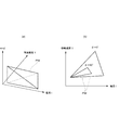
図4の(a)及び(b)は、ベースプレート41が鉛直面とされた基面傾斜角θが0°のときのトーチ17の移動速度V及びアークの発生のための電流値IのプロセスウインドウPWを示している。図4の(a)及び(b)に示すように、移動速度V及び電流値IのプロセスウインドウPWは、軌道傾斜角φが大きくなるにしたがって重力の影響が大きくなるため次第に狭くなる範囲となっている。
制御部37は、例えば、基面傾斜角θが0°のときに、図4の(a)及び(b)に示すプロセスウインドウPWに対して、移動軌跡の軌道傾斜角φをあてはめることで、選択したビード高さBH及びビード幅BWで溶着ビード25を形成するためのトーチ17の移動速度V及びアークを発生させるための電流値Iを決定する。
制御部37は、移動速度V及び電流値Iの決定後、溶接ロボット19を駆動させ、生成された移動軌跡に沿って溶着ビード25を形成する際に、決定した移動速度Vでトーチ17を移動させ、決定した電流値Iでアークを発生させる。そして、ベースプレート41上に、選択したビード高さBH及びビード幅BWの溶着ビード25を形成する。これにより、ベースプレート41には、垂れやハンピングを生じさせることなく、生成した移動軌跡に沿って溶着ビード25が形成され、造形物Wが造形される。
ここで、造形物の形状等によっては、どうしてもマップから選択したビード高さBHやビード幅BWとはサイズが異なる溶着ビード25を積層してしまう可能性がある。その場合には、マップを用いてビード高さBHやビード幅BWの選択を修正すればよい。
この修正をフィードバック制御で実施する際の制御パラメータとしては、ビード高さBHやビード幅BWは、あくまで目標とする指標であって、直接制御できるパラメータではないため適切でない。一方、基面傾斜角θ、及び軌道傾斜角φは、ベースプレート41が載置されたステージの移動やトーチの移動方向等により、ある程度調整できるパラメータである。そこで、基面傾斜角θ、及び軌道傾斜角φを制御パラメータに用いてビード高さBHやビード幅BWの修正を行う。このとき、cosθsinφの値の連続的(又は段階的)な変化の情報を予め求めておき、この情報を盛り込んで能動的にフィードバック制御することで、効率のよい修正が行える。
具体的には、表1に示すように、基面傾斜角θ0、及び軌道傾斜角φ0で溶着ビードを形成する際、ビード形成の実績情報であるマップを参照して、ビード高さBH0及びビード幅BW0を選択する。選択されたBH0,BW0に対応するビード形成を制御の指令値として、溶着ビードを形成する。その溶着ビードをビード形成後に計測したところ、ビードの基面傾斜角がθm、軌道傾斜角がφmであったとする。また、これらθm、φmをマップに照合すると、実際に積層される溶着ビードのビード幅はBW1、ビード高さはBH1であると期待されるとする。

この場合、実際に積層される溶着ビードのサイズが正確にBW0,BH0となるように、当初選択したビードサイズであるBH0,BW0の値を修正する。つまり、ビードサイズをBH0,BW0に設定して溶着ビードを形成しても、実際の溶着ビードのビードサイズがBH0,BW0とは異なってしまう。そこで、マップから当初選択したBH0,BW0の値を、ビード形性後のビードサイズが適正値(BH0,BW0)になるように予め修正しておく。
具体的には、計測された溶着ビードの形状(ビード高さ、ビード幅)に対応する基面傾斜角θの実績値θmと、軌道傾斜角φの実績値φmとを計測により求める。
次に、基面傾斜角θと軌道傾斜角φの実績値θm、φmに対応するビード高さBH1及びビード幅BW1をマップから求める。そして、当初選択したビード高さBH0とビード幅BW0との差分ΔBH(=BH0-BH1),ΔBW(=BW0-BW1)を求める。
求めた差分ΔBH,ΔBWを加算したビード高さBH2(=BH1+ΔBH)及びビード幅BW2(=BW1+ΔBW)の条件でマップを検索し、これに対応する基面傾斜角θ+αと軌道傾斜角φ+βとを求める(α、βは補正された角度)。
そして、ビード形成の制御指令として、基面傾斜角θ+α、軌道傾斜角φ+βとなるように溶着ビードを積層する指令に修正する。つまり、当初選択したビード条件の選択結果(BH0,BW0)を修正値(BH2,BW2)に変更した状態でビード形成する。
このようにして、予め用意されたマップから選択したビード高さBH0とビード幅BW0を満たす溶着ビードを実際に積層できるように、制御指令を修正することができる。なお、ビード高さやビード幅の実績値を造形中の表面形状計測から直接評価しない理由は、造形中の表面形状から各溶接ビードの正確なビード高さやビード幅を評価することが困難だからである。
溶着ビードの表面形状測定は、例えば光切断法などが利用可能である。その場合、基面傾斜角θについては、図2Aで示される溶着ビード25の上面がなす形状を測ることで、基面がベースプレート41でなく、溶着ビード25のなす上面である場合にも厳密に対応できる。また、軌道傾斜角φについては、積層された溶着ビードの形状を3次元形状計測した結果から最も高い頂点を抽出するなどして溶着ビードの延伸方向を求め、この溶着ビードの延伸方向から求めることができる。
さらに、基面傾斜角θは、図3の(a)や(b)に示すような外観写真をビード積層毎にカメラで撮像すれば、十分な精度で把握することができる。また、ビード層の2層目以降はビード上面が基面になるが、これを正確に把握できる。
そして、軌道傾斜角φは、演算による方法以外にも、トーチにレーザートラッカーを取り付けるなどして求めることもできる。
そして、軌道傾斜角φは、演算による方法以外にも、トーチにレーザートラッカーを取り付けるなどして求めることもできる。
このように、予め実績値θmやφmを把握しておけば、その情報を盛り込んで、より適切な形状の条件の溶着ビードを選択できる。
さらに、基面傾斜角θ又は軌道傾斜角φのいずれか一方を固定値と見なすことで、フィードバック制御によるcosθsinφの値の把握をより短時間で行うこともできる。
上記の方法は、マップから所定の条件を満たすビード条件の選択を、実績から考えてやり直すフィードバック制御の一例であるが、選択したビードの条件と合致するように、溶接条件等を変更するフィードバック制御としてもよい。
具体的には、cosθsinφの値が大きくなると、溶着ビードは重力影響によって垂れやすくなる。そのため、マップから選択した基面傾斜角θ及び軌道傾斜角φにより算出されるcosθsinφの値が過大となる場合は、入熱量を下げて溶着ビードの垂れを防止する。例えば、溶接電流を下げる、トーチ移動速度を上げるなどの溶接条件を変更する。
以上、説明したように、本実施形態にかかる造形物の製造方法及び製造装置によれば、ベースプレート41の表面からなる基面の鉛直面に対する基面傾斜角θ及び基面上におけるトーチ17の軌道方向の鉛直方向に対する軌道傾斜角φに応じたビード高さBH及びビード幅BWをマップから選択し、その選択したビード高さBH及びビード幅BWで溶着ビード25を形成する。したがって、あらゆる基面傾斜角θ及び軌道傾斜角φにおいて溶着ビード25に垂れやハンピングが生じないビード高さBH及びビード幅BWのマップを予め設定しておくことで、溶着ビード25を形成する基面が鉛直面に対して傾いていたり、トーチ17の軌道方向が鉛直方向に対して傾いていたりしても、垂れやハンピングなどの発生を極力抑えつつ溶着ビード25を形成することができる。これにより、タクトタイムを抑えつつ高品質な造形物Wを製造できる。
また、マップから選択したビード高さBH、ビード幅BWを、実績値を用いてより適正な値に変更したり、トーチ17の移動速度V及びアークを発生させる電流値Iを制御したりすることで、溶着ビード25を容易にかつ的確に形成することができる。
特に、重力影響の指標としてcosθsinφを用いたマップからビード高さBH及びビード幅BWを選択して溶着ビード25を形成することで、重力影響による垂れが抑制された溶着ビード25を円滑に形成することができる。
本発明は上記の実施形態に限定されるものではなく、実施形態の各構成を相互に組み合わせることや、明細書の記載、並びに周知の技術に基づいて、当業者が変更、応用することも本発明の予定するところであり、保護を求める範囲に含まれる。
例えば、上記実施形態では、ベースプレート41の表面を基面として溶着ビード25を形成する場合を例示したが、溶着ビード25を形成する基面は、ベースプレート41などの板体に限らない。例えば、溶着ビード25を積層させる場合は、下層側の溶着ビード25の上面が基面となる。
例えば、本構成の積層造形装置11は、移動機構として溶接ロボット19を用いているが、これに限らず、トーチ17をベースプレート41に対して相対移動できる構成であってもよい。その場合、トーチ17の軌道とは、トーチ17とベースプレート41との相対移動の軌道を意味する。
以上の通り、本明細書には次の事項が開示されている。
(1) 溶加材を溶融及び凝固させた溶着ビードをトーチで形成して造形物を造形する造形物の製造方法であって、
前記溶着ビードを形成する基面が鉛直方向と成す基面傾斜角θと、前記基面上における前記トーチの軌道方向が鉛直方向と成す軌道傾斜角φとに応じたビード高さBH及びビード幅BWのマップを予め作成し、
前記基面に溶着ビードを形成する際に、前記基面傾斜角θと前記軌道傾斜角φとに応じて前記マップからビード高さBH0及びビード幅BW0を選択し、
選択したビード高さBH0及びビード幅BW0で前記溶着ビードを形成する
造形物の製造方法。
この造形物の製造方法によれば、基面の鉛直面に対する基面傾斜角θ及び基面上におけるトーチの軌道方向の鉛直方向に対する軌道傾斜角φに応じたビード高さBH0及びビード幅BW0をマップから選択し、その選択したビード高さBH0及びビード幅BW0で溶着ビードを形成する。したがって、あらゆる基面傾斜角θ及び軌道傾斜角φにおいて溶着ビードに垂れやハンピングが生じないビード高さBH0及びビード幅BW0のマップを予め設定しておくことで、溶着ビードを形成する基面が鉛直面に対して傾いていたり、トーチの軌道方向が鉛直方向に対して傾いていたりしても、垂れやハンピングなどの発生を極力抑えつつ溶着ビードを形成することができる。これにより、タクトタイムを抑えつつ高品質な造形物を製造できる。
(1) 溶加材を溶融及び凝固させた溶着ビードをトーチで形成して造形物を造形する造形物の製造方法であって、
前記溶着ビードを形成する基面が鉛直方向と成す基面傾斜角θと、前記基面上における前記トーチの軌道方向が鉛直方向と成す軌道傾斜角φとに応じたビード高さBH及びビード幅BWのマップを予め作成し、
前記基面に溶着ビードを形成する際に、前記基面傾斜角θと前記軌道傾斜角φとに応じて前記マップからビード高さBH0及びビード幅BW0を選択し、
選択したビード高さBH0及びビード幅BW0で前記溶着ビードを形成する
造形物の製造方法。
この造形物の製造方法によれば、基面の鉛直面に対する基面傾斜角θ及び基面上におけるトーチの軌道方向の鉛直方向に対する軌道傾斜角φに応じたビード高さBH0及びビード幅BW0をマップから選択し、その選択したビード高さBH0及びビード幅BW0で溶着ビードを形成する。したがって、あらゆる基面傾斜角θ及び軌道傾斜角φにおいて溶着ビードに垂れやハンピングが生じないビード高さBH0及びビード幅BW0のマップを予め設定しておくことで、溶着ビードを形成する基面が鉛直面に対して傾いていたり、トーチの軌道方向が鉛直方向に対して傾いていたりしても、垂れやハンピングなどの発生を極力抑えつつ溶着ビードを形成することができる。これにより、タクトタイムを抑えつつ高品質な造形物を製造できる。
(2) 前記溶着ビードを形成する前に、既に積層した溶着ビードの表面形状を計測することで、前記ビード高さBH0及び前記ビード幅BW0に対応する前記基面傾斜角の実績値θmと前記軌道傾斜角の実績値φmを求め、
前記実績値θm,φmに対応する対応ビード高さBH1と対応ビード幅BW1とを前記マップから算出し、
前記溶着ビードを形成する際に選択した前記ビード高さBH0及び前記ビード幅BW0と、前記対応ビード高さBH1と前記対応ビード幅BW1との差分BH0-BH1,BW0-BW1を求め、
求めた前記差分を前記ビード高さBH0及び前記ビード幅BW0にそれぞれ加算した補正後ビード高さBH2及び補正後ビード幅BW2を求め、
前記マップから前記補正後ビード高さBH2及び補正後ビード幅BW2に対応する補正基面傾斜角θ、補正軌道傾斜角φを求め、
求めた前記補正基面傾斜角θ、補正軌道傾斜角φで前記溶着ビードを形成する
工程を含む(1)に記載の造形物の製造方法。
この造形物の製造方法によれば、既に積層の実績のある基面傾斜角や軌道傾斜角に近づけるように、ビード高さとビード幅を修正することで、垂れやハンピングが抑制される適切なビード形状にできる。
前記実績値θm,φmに対応する対応ビード高さBH1と対応ビード幅BW1とを前記マップから算出し、
前記溶着ビードを形成する際に選択した前記ビード高さBH0及び前記ビード幅BW0と、前記対応ビード高さBH1と前記対応ビード幅BW1との差分BH0-BH1,BW0-BW1を求め、
求めた前記差分を前記ビード高さBH0及び前記ビード幅BW0にそれぞれ加算した補正後ビード高さBH2及び補正後ビード幅BW2を求め、
前記マップから前記補正後ビード高さBH2及び補正後ビード幅BW2に対応する補正基面傾斜角θ、補正軌道傾斜角φを求め、
求めた前記補正基面傾斜角θ、補正軌道傾斜角φで前記溶着ビードを形成する
工程を含む(1)に記載の造形物の製造方法。
この造形物の製造方法によれば、既に積層の実績のある基面傾斜角や軌道傾斜角に近づけるように、ビード高さとビード幅を修正することで、垂れやハンピングが抑制される適切なビード形状にできる。
(3) アークを用いて前記溶加材を溶融及び凝固させて前記溶着ビードを形成する際に、前記トーチの移動速度及び前記アークを発生させる電流値を制御することで、前記マップから選択したビード高さ及びビード幅で前記溶着ビードを形成する(1)又は(2)に記載の造形物の製造方法。
この造形物の製造方法によれば、トーチの移動速度及びアークを発生させる電流値を制御することで、マップから選択したビード高さ及びビード幅で溶着ビードを容易にかつ的確に形成することができる。
この造形物の製造方法によれば、トーチの移動速度及びアークを発生させる電流値を制御することで、マップから選択したビード高さ及びビード幅で溶着ビードを容易にかつ的確に形成することができる。
(4) 前記溶着ビードを積層させて造形物を形成する(1)~(3)のいずれか一つに記載の造形物の製造方法。
この造形物の製造方法によれば、垂れやハンピングなどの不具合なく、溶着ビードを積層した造形物を製造することができる。
この造形物の製造方法によれば、垂れやハンピングなどの不具合なく、溶着ビードを積層した造形物を製造することができる。
(5) 前記マップの作成においては、前記基面傾斜角θと前記軌道傾斜角φに対する前記ビード高さBH及び前記ビード幅BWとの関係を、前記溶着ビードにおける重力影響の指標としてcosθsinφを用いて求める(1)~(4)のいずれか一つに記載の造形物の製造方法。
この造形物の製造方法によれば、重力影響の指標としてcosθsinφを用いたマップからビード高さ及びビード幅を選択して溶着ビードを形成することで、重力影響による垂れが抑制された溶着ビードを円滑に形成することができる。
この造形物の製造方法によれば、重力影響の指標としてcosθsinφを用いたマップからビード高さ及びビード幅を選択して溶着ビードを形成することで、重力影響による垂れが抑制された溶着ビードを円滑に形成することができる。
(6) 前記溶着ビードを形成する前に、既に積層した溶着ビードの表面形状を計測することで前記基面傾斜角の実績値θmと前記軌道傾斜角の実績値φmを算出し、
前記溶着ビードを形成する前にcosθmsinφmの値を算出して、既に前記マップから選択した前記基面傾斜角θ及び前記軌道傾斜角φより算出されるcosθsinφの値より大きい場合は、前記溶着ビードへの入熱量を減少させるフィードバック制御を行うことを特徴とする、(5)に記載の造形物の製造方法。
この造形物の製造方法によれば、選択したビードの条件と合致するように、溶接電流やトーチ速度の調整等によって入熱量を減少させることで、垂れやハンピングが抑制される適切なビード形状にできる。
前記溶着ビードを形成する前にcosθmsinφmの値を算出して、既に前記マップから選択した前記基面傾斜角θ及び前記軌道傾斜角φより算出されるcosθsinφの値より大きい場合は、前記溶着ビードへの入熱量を減少させるフィードバック制御を行うことを特徴とする、(5)に記載の造形物の製造方法。
この造形物の製造方法によれば、選択したビードの条件と合致するように、溶接電流やトーチ速度の調整等によって入熱量を減少させることで、垂れやハンピングが抑制される適切なビード形状にできる。
(7) 溶加材を溶融及び凝固させた溶着ビードにより、基面上に造形物を造形する造形物の製造装置であって、
前記溶着ビードを形成するトーチと、
前記トーチを前記基面に対して相対移動させる移動機構と、
前記基面が鉛直方向と成す基面傾斜角及び前記基面上における前記トーチの軌道方向が鉛直方向と成す軌道傾斜角に応じたビード高さ及びビード幅のマップが記憶された記憶部と、
前記基面に溶着ビードを形成する際に、前記記憶部の前記マップから前記基面傾斜角と前記軌道傾斜角とに応じたビード高さ及びビード幅を選択して前記移動機構及び前記トーチを制御し、前記溶着ビードを形成する制御部と、
を備える造形物の製造装置。
この造形物の製造装置によれば、記憶部に記憶された、基面の鉛直面に対する基面傾斜角及び基面上におけるトーチの軌道方向の鉛直方向に対する軌道傾斜角に応じたビード高さ及びビード幅のマップから、形成する溶着ビードのビード高さ及びビード幅を制御部が選択する。そして、制御部が移動機構及びトーチを制御し、選択したビード高さ及びビード幅で溶着ビードを形成する。したがって、あらゆる基面傾斜角及び軌道傾斜角において溶着ビードに垂れやハンピングが生じないビード高さ及びビード幅のマップを予め設定しておくことで、溶着ビードを形成する基面が鉛直面に対して傾いていたり、トーチの軌道方向が鉛直方向に対して傾いていたりしても、垂れやハンピングなどの発生を極力抑えつつ溶着ビードを形成することができる。これにより、タクトタイムを抑えつつ高品質な造形物を製造できる。
前記溶着ビードを形成するトーチと、
前記トーチを前記基面に対して相対移動させる移動機構と、
前記基面が鉛直方向と成す基面傾斜角及び前記基面上における前記トーチの軌道方向が鉛直方向と成す軌道傾斜角に応じたビード高さ及びビード幅のマップが記憶された記憶部と、
前記基面に溶着ビードを形成する際に、前記記憶部の前記マップから前記基面傾斜角と前記軌道傾斜角とに応じたビード高さ及びビード幅を選択して前記移動機構及び前記トーチを制御し、前記溶着ビードを形成する制御部と、
を備える造形物の製造装置。
この造形物の製造装置によれば、記憶部に記憶された、基面の鉛直面に対する基面傾斜角及び基面上におけるトーチの軌道方向の鉛直方向に対する軌道傾斜角に応じたビード高さ及びビード幅のマップから、形成する溶着ビードのビード高さ及びビード幅を制御部が選択する。そして、制御部が移動機構及びトーチを制御し、選択したビード高さ及びビード幅で溶着ビードを形成する。したがって、あらゆる基面傾斜角及び軌道傾斜角において溶着ビードに垂れやハンピングが生じないビード高さ及びビード幅のマップを予め設定しておくことで、溶着ビードを形成する基面が鉛直面に対して傾いていたり、トーチの軌道方向が鉛直方向に対して傾いていたりしても、垂れやハンピングなどの発生を極力抑えつつ溶着ビードを形成することができる。これにより、タクトタイムを抑えつつ高品質な造形物を製造できる。
(8) 前記制御部は、前記マップから選択したビード高さ及びビード幅で前記溶着ビードを形成するように、アークを用いて前記溶加材を溶融及び凝固させて前記溶着ビードを形成する際に、前記トーチの移動速度及び前記アークを発生させる電流値を制御する(7)に記載の造形物の製造装置。
この造形物の製造装置によれば、制御部が、トーチの移動速度及びアークを発生させる電流値を制御することで、マップから選択したビード高さ及びビード幅で溶着ビードを容易にかつ的確に形成することができる。
この造形物の製造装置によれば、制御部が、トーチの移動速度及びアークを発生させる電流値を制御することで、マップから選択したビード高さ及びビード幅で溶着ビードを容易にかつ的確に形成することができる。
(9) 前記マップにおいては、前記基面傾斜角θと前記軌道傾斜角φに対する前記ビード高さ及び前記ビード幅との関係が、前記溶着ビードにおける重力影響の指標としてcosθsinφを用いて求められている(7)又は(8)に記載の造形物の製造装置。
この造形物の製造装置によれば、垂れが抑制された溶着ビードを円滑に形成することができる。
この造形物の製造装置によれば、垂れが抑制された溶着ビードを円滑に形成することができる。
本出願は、2017年11月15日出願の日本特許出願(特願2017-220213)に基づくものであり、その内容はここに参照として取り込まれる。
11 積層造形装置(製造装置)
17 トーチ
19 溶接ロボット(移動機構)
25 溶着ビード
35 記憶部
37 制御部
BH ビード高さ
BW ビード幅
I 電流値
M 溶加材
V 移動速度
W 造形物
θ 基面傾斜角
φ 軌道傾斜角
17 トーチ
19 溶接ロボット(移動機構)
25 溶着ビード
35 記憶部
37 制御部
BH ビード高さ
BW ビード幅
I 電流値
M 溶加材
V 移動速度
W 造形物
θ 基面傾斜角
φ 軌道傾斜角
Claims (12)
- 溶加材を溶融及び凝固させた溶着ビードをトーチで形成して造形物を造形する造形物の製造方法であって、
前記溶着ビードを形成する基面が鉛直方向と成す基面傾斜角θと、前記基面上における前記トーチの軌道方向が鉛直方向と成す軌道傾斜角φとに応じたビード高さBH及びビード幅BWのマップを予め作成し、
前記基面に溶着ビードを形成する際に、前記基面傾斜角θと前記軌道傾斜角φとに応じて前記マップからビード高さBH0及びビード幅BW0を選択し、
選択したビード高さBH0及びビード幅BW0で前記溶着ビードを形成する
造形物の製造方法。 - 前記溶着ビードを形成する前に、既に積層した溶着ビードの表面形状を計測することで、前記ビード高さBH0及び前記ビード幅BW0に対応する前記基面傾斜角の実績値θmと前記軌道傾斜角の実績値φmを求め、
前記実績値θm,φmに対応する対応ビード高さBH1と対応ビード幅BW1とを前記マップから算出し、
前記溶着ビードを形成する際に選択した前記ビード高さBH0及び前記ビード幅BW0と、前記対応ビード高さBH1と前記対応ビード幅BW1との差分BH0-BH1,BW0-BW1を求め、
求めた前記差分を前記ビード高さBH0及び前記ビード幅BW0にそれぞれ加算した補正後ビード高さBH2及び補正後ビード幅BW2を求め、
前記マップから前記補正後ビード高さBH2及び補正後ビード幅BW2に対応する補正基面傾斜角θ、補正軌道傾斜角φを求め、
求めた前記補正基面傾斜角θ、補正軌道傾斜角φで前記溶着ビードを形成する
工程を含む請求項1に記載の造形物の製造方法。 - アークを用いて前記溶加材を溶融及び凝固させて前記溶着ビードを形成する際に、前記トーチの移動速度及び前記アークを発生させる電流値を制御することで、前記マップから選択したビード高さ及びビード幅で前記溶着ビードを形成する請求項1に記載の造形物の製造方法。
- アークを用いて前記溶加材を溶融及び凝固させて前記溶着ビードを形成する際に、前記トーチの移動速度及び前記アークを発生させる電流値を制御することで、前記マップから選択したビード高さ及びビード幅で前記溶着ビードを形成する請求項2に記載の造形物の製造方法。
- 前記溶着ビードを積層させて造形物を形成する請求項1~4のいずれか一項に記載の造形物の製造方法。
- 前記マップの作成においては、前記基面傾斜角θと前記軌道傾斜角φに対する前記ビード高さBH及び前記ビード幅BWとの関係を、前記溶着ビードにおける重力影響の指標としてcosθsinφを用いて求める請求項1~4のいずれか一項に記載の造形物の製造方法。
- 前記マップの作成においては、前記基面傾斜角θと前記軌道傾斜角φに対する前記ビード高さBH及び前記ビード幅BWとの関係を、前記溶着ビードにおける重力影響の指標としてcosθsinφを用いて求める請求項5に記載の造形物の製造方法。
- 前記溶着ビードを形成する前に、既に積層した溶着ビードの表面形状を計測することで前記基面傾斜角の実績値θmと前記軌道傾斜角の実績値φmを算出し、
前記溶着ビードを形成する前にcosθmsinφmの値を算出して、既に前記マップから選択した前記基面傾斜角θ及び前記軌道傾斜角φより算出されるcosθsinφの値より大きい場合は、前記溶着ビードへの入熱量を減少させるフィードバック制御を行うことを特徴とする、請求項6に記載の造形物の製造方法。 - 前記溶着ビードを形成する前に、既に積層した溶着ビードの表面形状を計測することで前記基面傾斜角の実績値θmと前記軌道傾斜角の実績値φmを算出し、
前記溶着ビードを形成する前にcosθmsinφmの値を算出して、既に前記マップから選択した前記基面傾斜角θ及び前記軌道傾斜角φより算出されるcosθsinφの値より大きい場合は、前記溶着ビードへの入熱量を減少させるフィードバック制御を行うことを特徴とする、請求項7に記載の造形物の製造方法。 - 溶加材を溶融及び凝固させた溶着ビードにより、基面上に造形物を造形する造形物の製造装置であって、
前記溶着ビードを形成するトーチと、
前記トーチを前記基面に対して相対移動させる移動機構と、
前記基面が鉛直方向と成す基面傾斜角及び前記基面上における前記トーチの軌道方向が鉛直方向と成す軌道傾斜角に応じたビード高さ及びビード幅のマップが記憶された記憶部と、
前記基面に溶着ビードを形成する際に、前記記憶部の前記マップから前記基面傾斜角と前記軌道傾斜角とに応じたビード高さ及びビード幅を選択して前記移動機構及び前記トーチを制御し、前記溶着ビードを形成する制御部と、
を備える造形物の製造装置。 - 前記制御部は、前記マップから選択したビード高さ及びビード幅で前記溶着ビードを形成するように、アークを用いて前記溶加材を溶融及び凝固させて前記溶着ビードを形成する際に、前記トーチの移動速度及び前記アークを発生させる電流値を制御する請求項10に記載の造形物の製造装置。
- 前記マップにおいては、前記基面傾斜角θと前記軌道傾斜角φに対する前記ビード高さ及び前記ビード幅との関係が、前記溶着ビードにおける重力影響の指標としてcosθsinφを用いて求められている請求項10又は11に記載の造形物の製造装置。
Priority Applications (3)
| Application Number | Priority Date | Filing Date | Title |
|---|---|---|---|
| CN201880073841.1A CN111417485B (zh) | 2017-11-15 | 2018-11-06 | 造型物的制造方法以及制造装置 |
| US16/763,182 US11400535B2 (en) | 2017-11-15 | 2018-11-06 | Method and device for manufacturing shaped objects |
| EP18879354.1A EP3711888B1 (en) | 2017-11-15 | 2018-11-06 | Method and device for manufacturing shaped objects |
Applications Claiming Priority (2)
| Application Number | Priority Date | Filing Date | Title |
|---|---|---|---|
| JP2017220213A JP6737762B2 (ja) | 2017-11-15 | 2017-11-15 | 造形物の製造方法及び製造装置 |
| JP2017-220213 | 2017-11-15 |
Publications (1)
| Publication Number | Publication Date |
|---|---|
| WO2019098097A1 true WO2019098097A1 (ja) | 2019-05-23 |
Family
ID=66537833
Family Applications (1)
| Application Number | Title | Priority Date | Filing Date |
|---|---|---|---|
| PCT/JP2018/041249 Ceased WO2019098097A1 (ja) | 2017-11-15 | 2018-11-06 | 造形物の製造方法及び製造装置 |
Country Status (5)
| Country | Link |
|---|---|
| US (1) | US11400535B2 (ja) |
| EP (1) | EP3711888B1 (ja) |
| JP (1) | JP6737762B2 (ja) |
| CN (1) | CN111417485B (ja) |
| WO (1) | WO2019098097A1 (ja) |
Cited By (2)
| Publication number | Priority date | Publication date | Assignee | Title |
|---|---|---|---|---|
| IT202100020801A1 (it) * | 2021-08-02 | 2023-02-02 | Sisqo S R L | Macchina laser per fabbricazione additiva |
| EP4143027A4 (en) * | 2020-05-01 | 2024-04-24 | Vulcanforms Inc. | Melt pool control in additive manufacturing systems |
Families Citing this family (11)
| Publication number | Priority date | Publication date | Assignee | Title |
|---|---|---|---|---|
| US11292071B2 (en) * | 2017-11-15 | 2022-04-05 | Kobe Steel, Ltd. | Method for producing molded article, production device, and molded article |
| JP7538388B2 (ja) * | 2020-02-21 | 2024-08-22 | 三菱重工コンプレッサ株式会社 | 金属積層造形方法 |
| JP7339215B2 (ja) * | 2020-07-20 | 2023-09-05 | 株式会社神戸製鋼所 | 積層造形物の製造システム、積層造形物の製造方法、及び積層造形物の製造プログラム |
| CN112149198B (zh) * | 2020-09-14 | 2022-05-17 | 贵州翰凯斯智能技术有限公司 | 一种电弧熔丝增材制造路径生成方法 |
| JP7376455B2 (ja) * | 2020-10-28 | 2023-11-08 | 株式会社神戸製鋼所 | 積層計画作成方法 |
| JP2022163944A (ja) * | 2021-04-15 | 2022-10-27 | 国立大学法人京都大学 | 付加加工装置、付加加工装置の制御方法、および、付加加工装置の制御プログラム |
| JP7553400B2 (ja) * | 2021-04-16 | 2024-09-18 | 株式会社神戸製鋼所 | 積層造形方法、積層造形装置、及び積層造形物を造形するプログラム |
| IT202100020798A1 (it) * | 2021-08-02 | 2023-02-02 | Ryzen S R L | Macchina laser per fabbricazione additiva |
| CN114985870A (zh) * | 2022-06-27 | 2022-09-02 | 暨南大学 | 一种原位增材再制造成形方法 |
| US20240017340A1 (en) * | 2022-07-15 | 2024-01-18 | Relativity Space, Inc. | Systems for Horizontal Additive Manufacturing and Methods Thereof |
| JP7688010B2 (ja) * | 2022-12-21 | 2025-06-03 | 株式会社神戸製鋼所 | 造形物の製造方法及び製造装置 |
Citations (7)
| Publication number | Priority date | Publication date | Assignee | Title |
|---|---|---|---|---|
| JPS6127175A (ja) * | 1984-06-19 | 1986-02-06 | エム・ア−・エン・マシ−ネンフアブリ−ク・アウクスブルク−ニユルンベルク・アクチエンゲゼルシヤフト | 回転対称な物理的曲面をもつ部材を溶接材料から製造する方法 |
| JPH04336304A (ja) * | 1991-01-21 | 1992-11-24 | Gebr Sulzer Ag | 金属製品の製造方法及び製造装置 |
| JP2007275945A (ja) * | 2006-04-07 | 2007-10-25 | Asahi Glass Co Ltd | 三次元自由形状の造形物を製作する造形方法及びその装置 |
| JP2015160217A (ja) | 2014-02-26 | 2015-09-07 | 国立大学法人東京農工大学 | 三次元造形装置、三次元造形物の造形方法、および三次元製造装置の制御プログラム |
| JP2015182083A (ja) * | 2014-03-20 | 2015-10-22 | 日立金属株式会社 | 金型表面への肉盛溶接方法 |
| JP2016135911A (ja) * | 2014-11-11 | 2016-07-28 | ディーエムジー モリ ユーエスエイDMG Mori USA | 付加製造用の工作機械システム及び方法 |
| JP2017220213A (ja) | 2016-06-01 | 2017-12-14 | 株式会社小松製作所 | 加工負荷解析装置、加工負荷解析プログラム、及び加工負荷解析システム |
Family Cites Families (18)
| Publication number | Priority date | Publication date | Assignee | Title |
|---|---|---|---|---|
| JP2003266174A (ja) * | 2002-03-13 | 2003-09-24 | Honda Motor Co Ltd | 三次元形状物の製造方法 |
| JP5190023B2 (ja) * | 2009-05-20 | 2013-04-24 | 株式会社神戸製鋼所 | 溶接設定装置、溶接ロボットシステムおよび溶接設定プログラム |
| CN202684435U (zh) * | 2012-05-23 | 2013-01-23 | 广东长征机械有限公司 | 一种可倾斜的回转工作台装置 |
| CN104190927B (zh) * | 2014-08-11 | 2016-05-18 | 苏州大学 | 一种同步送粉空间激光加工与三维成形方法及装置 |
| EP3191992B1 (en) * | 2014-09-09 | 2020-11-25 | Cornell University | System and methods for three-dimensional printing |
| TWI611909B (zh) * | 2014-11-29 | 2018-01-21 | National Tsing Hua University | 彈性變向佈料高速3d成形技術 |
| US10850356B2 (en) * | 2015-02-25 | 2020-12-01 | Hobart Brothers Llc | Aluminum metal-cored welding wire |
| US10307957B2 (en) * | 2015-03-10 | 2019-06-04 | Siemens Product Lifecycle Management Software Inc. | Apparatus and method for additive manufacturing |
| KR101723726B1 (ko) * | 2015-03-24 | 2017-04-05 | 서울시립대학교 산학협력단 | 프린터 인쇄기법을 이용하여 다이오드를 제작하는 장치 및 방법 |
| KR20170047571A (ko) * | 2015-10-23 | 2017-05-08 | 엘지전자 주식회사 | 3d 프린터 |
| US20180370133A1 (en) * | 2015-11-16 | 2018-12-27 | Boston Inventions, LLC | Three-dimensional printer utilizing a rotating and tilting printing surface and spiral filament extrusion to form helical filament structures |
| CN105921852B (zh) * | 2016-06-08 | 2017-12-19 | 西南交通大学 | 倾斜薄壁结构件电弧填丝增材制造方法 |
| CN106825581B (zh) * | 2016-12-30 | 2019-03-01 | 青岛卓思三维智造技术有限公司 | 金属表面重熔方法及装置 |
| CN111712342A (zh) * | 2017-07-21 | 2020-09-25 | 加拿大派罗杰尼斯有限公司 | 用于使用推力器辅助等离子体雾化以大规模成本有效地生产超细球形粉末的方法 |
| WO2019074827A1 (en) * | 2017-10-09 | 2019-04-18 | Sciaky, Inc. | ELECTRON BEAM ADDITIVE MANUFACTURING SYSTEM AND CONTROL COMPONENTS |
| WO2019198212A1 (ja) * | 2018-04-12 | 2019-10-17 | 三菱電機株式会社 | 付加製造装置、付加製造システムおよび付加製造方法 |
| GB2569673B (en) * | 2018-08-24 | 2020-01-08 | Univ Cranfield | Additive Manufacture |
| WO2020263844A1 (en) * | 2019-06-24 | 2020-12-30 | Illinois Tool Works Inc. | Systems and methods for height control in laser metal deposition |
-
2017
- 2017-11-15 JP JP2017220213A patent/JP6737762B2/ja active Active
-
2018
- 2018-11-06 CN CN201880073841.1A patent/CN111417485B/zh active Active
- 2018-11-06 EP EP18879354.1A patent/EP3711888B1/en active Active
- 2018-11-06 WO PCT/JP2018/041249 patent/WO2019098097A1/ja not_active Ceased
- 2018-11-06 US US16/763,182 patent/US11400535B2/en active Active
Patent Citations (7)
| Publication number | Priority date | Publication date | Assignee | Title |
|---|---|---|---|---|
| JPS6127175A (ja) * | 1984-06-19 | 1986-02-06 | エム・ア−・エン・マシ−ネンフアブリ−ク・アウクスブルク−ニユルンベルク・アクチエンゲゼルシヤフト | 回転対称な物理的曲面をもつ部材を溶接材料から製造する方法 |
| JPH04336304A (ja) * | 1991-01-21 | 1992-11-24 | Gebr Sulzer Ag | 金属製品の製造方法及び製造装置 |
| JP2007275945A (ja) * | 2006-04-07 | 2007-10-25 | Asahi Glass Co Ltd | 三次元自由形状の造形物を製作する造形方法及びその装置 |
| JP2015160217A (ja) | 2014-02-26 | 2015-09-07 | 国立大学法人東京農工大学 | 三次元造形装置、三次元造形物の造形方法、および三次元製造装置の制御プログラム |
| JP2015182083A (ja) * | 2014-03-20 | 2015-10-22 | 日立金属株式会社 | 金型表面への肉盛溶接方法 |
| JP2016135911A (ja) * | 2014-11-11 | 2016-07-28 | ディーエムジー モリ ユーエスエイDMG Mori USA | 付加製造用の工作機械システム及び方法 |
| JP2017220213A (ja) | 2016-06-01 | 2017-12-14 | 株式会社小松製作所 | 加工負荷解析装置、加工負荷解析プログラム、及び加工負荷解析システム |
Non-Patent Citations (1)
| Title |
|---|
| See also references of EP3711888A4 |
Cited By (2)
| Publication number | Priority date | Publication date | Assignee | Title |
|---|---|---|---|---|
| EP4143027A4 (en) * | 2020-05-01 | 2024-04-24 | Vulcanforms Inc. | Melt pool control in additive manufacturing systems |
| IT202100020801A1 (it) * | 2021-08-02 | 2023-02-02 | Sisqo S R L | Macchina laser per fabbricazione additiva |
Also Published As
| Publication number | Publication date |
|---|---|
| CN111417485A (zh) | 2020-07-14 |
| US20200391316A1 (en) | 2020-12-17 |
| EP3711888A4 (en) | 2021-09-01 |
| CN111417485B (zh) | 2021-12-21 |
| US11400535B2 (en) | 2022-08-02 |
| EP3711888A1 (en) | 2020-09-23 |
| JP2019089108A (ja) | 2019-06-13 |
| EP3711888B1 (en) | 2024-07-31 |
| JP6737762B2 (ja) | 2020-08-12 |
Similar Documents
| Publication | Publication Date | Title |
|---|---|---|
| WO2019098097A1 (ja) | 造形物の製造方法及び製造装置 | |
| JP6751040B2 (ja) | 積層造形物の製造方法、製造システム、及び製造プログラム | |
| CN111344096A (zh) | 层叠造形物的制造方法以及制造装置 | |
| JP6810018B2 (ja) | 積層造形物の製造方法 | |
| JP6978350B2 (ja) | ワーク姿勢調整方法、造形物の製造方法及び製造装置 | |
| WO2018180135A1 (ja) | 積層造形物の製造方法及び製造システム | |
| CN116490316A (zh) | 层叠计划作成方法 | |
| JP2019136711A (ja) | 積層造形物の製造方法 | |
| CN116685430A (zh) | 层叠造型物的制造方法 | |
| JP6802773B2 (ja) | 積層造形物の製造方法及び積層造形物 | |
| CN116096521B (zh) | 层叠造型物的制造方法 | |
| JP7028737B2 (ja) | 造形物の製造方法、製造装置及び造形物 | |
| WO2019098021A1 (ja) | 造形物の製造方法、製造装置及び造形物 | |
| JP7303162B2 (ja) | 積層造形物の製造方法 | |
| JP2019081187A (ja) | 積層造形物の製造方法 | |
| JP2020168642A (ja) | 積層造形物の製造方法及び積層造形物 | |
| JP6859471B1 (ja) | 積層造形物の製造方法 | |
| JP7688010B2 (ja) | 造形物の製造方法及び製造装置 | |
| JP7794721B2 (ja) | 造形物の製造方法及び積層計画方法 | |
| JP6783964B1 (ja) | 積層造形物の製造方法 | |
| JP2024013526A (ja) | 制御情報修正方法、制御情報修正装置及びプログラム | |
| JP2021137846A (ja) | 積層造形物の製造方法及び積層造形物 | |
| JP2021181209A (ja) | 積層造形物の製造方法及び積層造形システム |
Legal Events
| Date | Code | Title | Description |
|---|---|---|---|
| 121 | Ep: the epo has been informed by wipo that ep was designated in this application |
Ref document number: 18879354 Country of ref document: EP Kind code of ref document: A1 |
|
| NENP | Non-entry into the national phase |
Ref country code: DE |
|
| ENP | Entry into the national phase |
Ref document number: 2018879354 Country of ref document: EP Effective date: 20200615 |