WO2019098345A1 - トリクロロシラン製造装置およびトリクロロシランの製造方法 - Google Patents
トリクロロシラン製造装置およびトリクロロシランの製造方法 Download PDFInfo
- Publication number
- WO2019098345A1 WO2019098345A1 PCT/JP2018/042557 JP2018042557W WO2019098345A1 WO 2019098345 A1 WO2019098345 A1 WO 2019098345A1 JP 2018042557 W JP2018042557 W JP 2018042557W WO 2019098345 A1 WO2019098345 A1 WO 2019098345A1
- Authority
- WO
- WIPO (PCT)
- Prior art keywords
- trichlorosilane
- reaction
- filter
- filter element
- filter device
- Prior art date
- Legal status (The legal status is an assumption and is not a legal conclusion. Google has not performed a legal analysis and makes no representation as to the accuracy of the status listed.)
- Ceased
Links
Images

Classifications
-
- C—CHEMISTRY; METALLURGY
- C01—INORGANIC CHEMISTRY
- C01B—NON-METALLIC ELEMENTS; COMPOUNDS THEREOF; METALLOIDS OR COMPOUNDS THEREOF NOT COVERED BY SUBCLASS C01C
- C01B33/00—Silicon; Compounds thereof
- C01B33/08—Compounds containing halogen
- C01B33/107—Halogenated silanes
- C01B33/1071—Tetrachloride, trichlorosilane or silicochloroform, dichlorosilane, monochlorosilane or mixtures thereof
-
- C—CHEMISTRY; METALLURGY
- C01—INORGANIC CHEMISTRY
- C01B—NON-METALLIC ELEMENTS; COMPOUNDS THEREOF; METALLOIDS OR COMPOUNDS THEREOF NOT COVERED BY SUBCLASS C01C
- C01B33/00—Silicon; Compounds thereof
- C01B33/08—Compounds containing halogen
- C01B33/107—Halogenated silanes
- C01B33/1071—Tetrachloride, trichlorosilane or silicochloroform, dichlorosilane, monochlorosilane or mixtures thereof
- C01B33/10742—Tetrachloride, trichlorosilane or silicochloroform, dichlorosilane, monochlorosilane or mixtures thereof prepared by hydrochlorination of silicon or of a silicon-containing material
- C01B33/10757—Tetrachloride, trichlorosilane or silicochloroform, dichlorosilane, monochlorosilane or mixtures thereof prepared by hydrochlorination of silicon or of a silicon-containing material with the preferential formation of trichlorosilane
- C01B33/10763—Tetrachloride, trichlorosilane or silicochloroform, dichlorosilane, monochlorosilane or mixtures thereof prepared by hydrochlorination of silicon or of a silicon-containing material with the preferential formation of trichlorosilane from silicon
-
- B—PERFORMING OPERATIONS; TRANSPORTING
- B01—PHYSICAL OR CHEMICAL PROCESSES OR APPARATUS IN GENERAL
- B01D—SEPARATION
- B01D39/00—Filtering material for liquid or gaseous fluids
- B01D39/14—Other self-supporting filtering material ; Other filtering material
- B01D39/20—Other self-supporting filtering material ; Other filtering material of inorganic material, e.g. asbestos paper, metallic filtering material of non-woven wires
-
- B—PERFORMING OPERATIONS; TRANSPORTING
- B01—PHYSICAL OR CHEMICAL PROCESSES OR APPARATUS IN GENERAL
- B01D—SEPARATION
- B01D39/00—Filtering material for liquid or gaseous fluids
- B01D39/14—Other self-supporting filtering material ; Other filtering material
- B01D39/20—Other self-supporting filtering material ; Other filtering material of inorganic material, e.g. asbestos paper, metallic filtering material of non-woven wires
- B01D39/2027—Metallic material
-
- C—CHEMISTRY; METALLURGY
- C01—INORGANIC CHEMISTRY
- C01B—NON-METALLIC ELEMENTS; COMPOUNDS THEREOF; METALLOIDS OR COMPOUNDS THEREOF NOT COVERED BY SUBCLASS C01C
- C01B33/00—Silicon; Compounds thereof
- C01B33/08—Compounds containing halogen
- C01B33/107—Halogenated silanes
- C01B33/10778—Purification
Definitions
- the present invention relates to a trichlorosilane production apparatus and a method for producing trichlorosilane.
- Trichlorosilane is used in the manufacture of polycrystalline silicon used as semiconductor and solar cell material.
- Trichlorosilane is obtained, for example, through the following reaction path.
- metal silicon powder (Si) and hydrogen chloride (HCl) are reacted.
- trichlorosilane is generated as a main reaction as shown in Formula (1), but tetrachlorosilane (STC, SiCl 4 ) is generated as a side reaction as shown in Formula (2).
- Tetrachlorosilane is recycled after recovery and converted to trichlorosilane as shown in the formula (3).
- trichlorosilane may be produced by the reaction of formula (3) without using hydrogen chloride.
- the reaction product recovered from the reaction apparatus in which the above reaction is carried out contains a chlorosilane compound including trichlorosilane, low boiling point silane, tetrachlorosilane and the like, and therefore the reaction is necessary to obtain a high purity trichlorosilane gas. It is necessary to carry out the purification of the product.
- the reaction product also contains unreacted metal silicon powder. Therefore, when the reaction product is supplied as it is from the reaction apparatus to the downstream purification apparatus, erosion and clogging by the metal silicon powder occur in the purification apparatus. The unreacted metal silicon powder can be removed by providing a filter device between the reactor and the purification device.
- Patent Document 1 discloses an apparatus for producing trichlorosilane including a solid-gas separation apparatus provided with a sintered filter element made of metal which is a wear resistant material.
- One aspect of the present invention is made in view of the above problems, and its object is to prevent corrosion cracking (hereinafter referred to as “stress corrosion cracking”) due to corrosion and stress in a trichlorosilane production apparatus. To aim.
- the present invention includes the following configurations.
- a trichlorosilane comprising: a reactor for producing trichlorosilane using metal silicon powder; and a filter device for removing the reaction residue from a reaction product containing the trichlorosilane produced by the reactor and a reaction residue It is a manufacturing apparatus,
- the said filter apparatus is equipped with the filter element comprised from corrosion-resistant material,
- the trichlorosilane manufacturing apparatus characterized by the above-mentioned.
- corrosion and stress corrosion cracking due to hydrochloric acid generated in the filter element portion can be suppressed.
- a to B representing a numerical range means “more than A (including A and greater than A) B or less (including B and less than B)”.
- the filter element has a fine-grained structure so that trichlorosilane and tetrachlorosilane tend to remain, and the problems (i) and (ii) become apparent at the time of opening in periodic inspections and the like.
- the trichlorosilane manufacturing apparatus which concerns on one Embodiment of this invention solves the problem of the prior art mentioned above, and equips a filter element with corrosion resistance. The details will be described below.
- a trichlorosilane production apparatus is a reaction apparatus for producing trichlorosilane using metal silicon powder, and a reaction product containing trichlorosilane produced by the reaction apparatus and a reaction residue.
- the manufacturing method of the trichlorosilane which concerns on one Embodiment of this invention is characterized by having the process of manufacturing trichlorosilane using the said manufacturing apparatus.
- the reaction apparatus used in one embodiment of the present invention is not particularly limited as long as it is an apparatus for synthesizing a reaction product containing trichlorosilane using metal silicon powder, and may be a known apparatus.
- a reaction apparatus a fluidized bed system reaction apparatus is mentioned, for example.
- By using a fluidized bed reactor it is possible to continuously supply metal silicon powder and hydrogen chloride to continuously synthesize trichlorosilane.
- a fluidized bed type reaction apparatus an apparatus for reacting trichloromethane with metal silicon powder and hydrogen chloride gas to synthesize trichlorosilane is described as an example in FIG.
- An apparatus for reacting trichlorosilane with chlorosilane may be used.
- the reactor 2 includes a reaction vessel 10, a dispersion plate 20, and a heat medium pipe 30.
- metal silicon powder is supplied to the inside of the reaction container 10
- hydrogen chloride gas that reacts with metal silicon powder is supplied from the gas supply port 101 formed at the bottom of the reaction container 10.
- the dispersion plate 20 is provided on the gas supply port 101 of the reaction vessel 10, and disperses the hydrogen chloride gas supplied to the inside of the reaction vessel 10.
- the reaction apparatus 2 causes metal silicon powder in the inside of the reaction vessel 10 to react while flowing with hydrogen chloride gas (a place where the reaction is occurring is hereinafter referred to as a fluidized bed 40).
- a reaction product containing trichlorosilane synthesized by the reaction of metal silicon powder and hydrogen chloride gas and a reaction residue is taken out from the reaction product outlet 102 of the reaction vessel 10.
- a heat medium pipe 30 for circulating a heat medium is provided along the vertical direction (the direction parallel to the gravity). By flowing the heat medium through the heat medium pipe 30, the reaction heat due to the reaction between the metal silicon powder and the hydrogen chloride gas is removed.
- the shape of the reaction vessel 10 (in other words, the shape of the side wall of the reaction vessel 10) is not particularly limited.
- the side wall of the reaction vessel 10 surrounding the fluidized bed 40 may have a shape (not shown) such that the cross-sectional area of the cut surface orthogonal to the height direction of the reaction vessel 10 is constant or not It may be a tapered shape (FIG. 1) that becomes larger toward the end.
- the side wall has an increase in the cross-sectional area of the cut surface orthogonal to the height direction of the reaction vessel upwards It may be tapered. From the viewpoint of reducing the risk of erosion and preventing a local temperature rise, it is preferable that the shape of the reaction vessel 10 be a tapered shape.
- the flow of metal silicon powder and hydrogen chloride up to the reaction device 2 is, for example, described in Japanese Patent Application Laid-Open Publication No. 2011-184242, and thus the description thereof is omitted.
- known materials can be used without particular limitation, and the synthesis conditions can also be used without particular limitation as long as they are known conditions.
- metal silicon powder means a solid substance containing elemental silicon in metallic state such as metallurgical metal silicon, silicon iron, or polysilicon, and known materials can be used without any limitation.
- the metal silicon powder may contain impurities such as an iron compound, and the components and the content thereof are not particularly limited.
- Such metal silicon powder is usually used in the form of a fine powder having an average particle diameter of about 150 to 350 ⁇ m.
- the feed rates of the metallic silicon powder and hydrogen chloride are not particularly limited as long as the metallic silicon powder and hydrogen chloride can be fed at such a rate that the fluid bed can form a flow rate.
- the reaction temperature in the above reaction is appropriately determined in consideration of the material and capability of the reaction apparatus, the catalyst used, etc., but is generally set in the range of 200 to 500 ° C., particularly 250 to 400 ° C.
- the filter device is a device for removing the reaction residue containing unreacted metal silicon powder from the reaction product containing trichlorosilane and the reaction residue.
- the filter device comprises a filter element in which the pores are formed. Thereby, the filter device separates the reaction product into a component that can pass through the pores and a component (reaction residue) that can not pass through the pores.
- the filter device 3 shown in FIG. 1 will be described in detail as an example of the filter device.
- the filter device 3 includes a lower filter container 50, an upper filter container 60, a partition plate 70, and a filter element 80.
- the lower filter container 50 has a tapered bottom, a barrel shaped like a cylinder, and a filter device inlet 103 and a residue recovery port 105.
- the upper filter container 60 comprises a filter device outlet 104.
- the reaction product synthesized in the reactor 2 is sequentially supplied from the filter device inlet 103.
- the supplied reaction product is separated by the filter element 80 and discharged from the filter device outlet 104 and the residue recovery port 105.
- the lower filter container 50 and the upper filter container 60 are installed to be able to open and close.
- the partition plate 70 is a space on the side where the filter device inlet 103 is installed (hereinafter referred to as the filter device inlet side) and a side on which the filter device outlet 104 is installed (hereinafter, the filter device outlet) Divided into two)
- the partition plate 70 may be installed at the boundary between the lower filter container 50 and the upper filter container 60.
- the hole for holding the filter element 80 is opened in the partition plate 70, There is no restriction
- the filter element 80 has a cylindrical shape in which fine pores are formed.
- the filter element 80 is installed in the filter device 3 so as to be held in the hole of the partition plate 70.
- the filter element 80 connects the space on the inlet side of the filter device and the space on the outlet side of the filter device so that gas can flow through the pores.
- components capable of passing through the pores of the filter element 80 (hereinafter referred to as gas components) are discharged from the filter device outlet 104. Since the reaction product is sequentially supplied to the filter device 3, the filter device inlet side is positive pressure, the filter device outlet side is lower in pressure than the inlet, and the gas component is automatically discharged.
- the reaction product having a size larger than the pore diameter of the pores of the filter element 80 can not pass through the pores of the filter element 80, the reaction product remains on the filter device inlet side of the filter device 3.
- the filter container is pressurized to a certain pressure such as N 2 gas, H 2 gas or Ar gas, and held at a lower pressure than the filter downstream of the residue recovery port 105 It is preferable to carry out the discharge operation to discharge into another container. In the discharging operation, it is preferable to quickly open the valve of the connected pipe after holding both containers at different pressures, and discharge using the pressure difference between both containers.
- a certain pressure such as N 2 gas, H 2 gas or Ar gas
- the filter device 3 may be opened to the atmosphere by separating the lower filter container 50 and the upper filter container 60 of the filter device 3. is there.
- the reaction products remaining in the pores of the filter element 80 are removed and discharged by the backwashing and discharging operations as described above, but the reaction products are produced because the pores have a fine-grained structure. Some of them remain in the pores. Since the remaining reaction product contains trichlorosilane and the like, the water in the air and the remaining reaction product react with each other when the air is released to generate a high concentration of hydrochloric acid in the vicinity of the filter element 80, and the filter element 80 It becomes easy to corrode.
- the filter element 80 is made of a corrosion resistant material.
- corrosion resistant material refers to stress corrosion cracking as compared to stainless steel according to JIS G0576 "Test method for stress corrosion cracking of stainless steel” or JIS Z 2291 "High temperature gas corrosion test method for metal materials”. Materials intended to be excellent, or materials which were found to be extremely resistant to oxidation at high temperatures are intended.
- the term "a component is made of a corrosion resistant material” includes that the component is coated with a corrosion resistant material, that the component is forged or cast from a corrosion resistant material, and the like.
- the corrosion-resistant material used for the filter element 80 preferably contains nickel as an essential component, and preferably contains at least one selected from the group consisting of chromium, iron, tungsten, niobium, tantalum and molybdenum. .
- the content of nickel in 100% by weight of the corrosion resistant material is preferably 20 to 80% by weight, and more preferably 50 to 75% by weight.
- the content of chromium is preferably 10 to 25% by weight, and more preferably 14 to 23% by weight.
- the iron content is preferably 2 to 30% by weight, more preferably 3 to 8% by weight.
- the content of tungsten is preferably 0 to 5% by weight, and more preferably 0 to 4% by weight.
- the content of niobium is preferably 0 to 5% by weight, and more preferably 0 to 4% by weight.
- the content of tantalum is preferably 0 to 5% by weight, and more preferably 0 to 4% by weight.
- the content of molybdenum is preferably 1% by weight or more, and more preferably 5 to 20% by weight.
- Specific examples of such corrosion resistant materials include Inconel 600, Inconel 625, Inconel 825, Hastelloy C22, Hastelloy C276 and NAS 254N.
- a corrosion resistant material containing molybdenum as the filter element 80, it is possible to suppress not only corrosion and stress corrosion cracking but also intergranular corrosion (corrosion in which corrosion progresses along grain boundaries). Therefore, it is more preferable to use a corrosion resistant material containing molybdenum.
- a corrosion resistant material containing molybdenum Inconel 625, Inconel 825, Hastelloy C22, Hastelloy C276, NAS254N and the like can be mentioned.
- reaction product discharged from the trichlorosilane production apparatus 1 shown in FIG. 1 was treated using the filter apparatus 3 shown in FIG.
- the reaction product contains the following gas composition and dust components at a temperature of about 200.degree.
- Gas composition 3% by weight of H 2 , 17% by weight of TCS, 80% by weight of STC, and trace components (AlCl 3 , high-boiling components, etc.)
- Dust component Si, intermetallic compound with Si, SiC, Al, Ca slag, AlCl 3 , CaCl 2 , FeCl 2 and the like.
- Table 1 shows the material of the filter element 80, the evaluation of the corrosion resistance of the material, and the presence or absence of stress corrosion cracking after the actual operation.
- Table 2 shows the composition of the material used as the filter element 80.
- the filter element 80 no. 1 to No. A cylindrical filter element (3 mm thick, outer diameter 60 ⁇ ⁇ total length 1300 mm) made of the material shown in 5 and having fine pores formed was used. The filter element was put into practical use for 309 days, and the occurrence of stress corrosion cracking was confirmed.
- a reaction apparatus for producing trichlorosilane using metal silicon powder and a reaction product from a reaction product containing trichlorosilane produced by the reaction apparatus and a reaction residue
- a filter device for removing residue wherein the filter device comprises a filter element made of a corrosion resistant material.
- the corrosion resistant material preferably contains 1 wt% or more of molybdenum.
- the corrosion resistant material is preferably inconel 625 or hastelloy.
- a trichlorosilane production method includes the step of producing trichlorosilane using the trichlorosilane production device according to any one of the trichlorosilane production devices according to an aspect of the present invention. Is preferred.
- the present invention can be utilized for the production of trichlorosilane.
Landscapes
- Chemical & Material Sciences (AREA)
- Organic Chemistry (AREA)
- Inorganic Chemistry (AREA)
- Life Sciences & Earth Sciences (AREA)
- Geology (AREA)
- Chemical Kinetics & Catalysis (AREA)
- Silicon Compounds (AREA)
Abstract
フィルターエレメント(80)部分に発生する塩酸による、腐食および応力腐食割れを防ぐことを目的とする。トリクロロシランを生成する反応装置(2)と、反応残渣を除去するフィルター装置(3)と、を備えたトリクロロシラン製造装置(1)であって、前記フィルター装置(3)は、耐食性材料から構成されたフィルターエレメントを備える。
Description
本発明はトリクロロシラン製造装置およびトリクロロシランの製造方法に関する。
高純度のトリクロロシラン(TCS、SiHCl3)は、半導体及び太陽電池の材料として用いられる多結晶シリコンの製造に使用される。トリクロロシランは、例えば、以下の反応経路を経て得られる。まず、金属シリコン粉体(Si)と塩化水素(HCl)とを反応させる。その場合に、主反応として、式(1)に示すようにトリクロロシランが生成されるが、副反応として式(2)に示すようにテトラクロロシラン(STC、SiCl4)が生じる。テトラクロロシランは回収後再利用され、式(3)に示すようにトリクロロシランへと転化される。また、塩化水素を用いずに、式(3)の反応によってトリクロロシランを製造する場合もある。
Si+3HCl→SiHCl3+H2 (1)
Si+4HCl→SiCl4+2H2 (2)
3SiCl4+2H2+Si→4SiHCl3 (3)
Si+3HCl→SiHCl3+H2 (1)
Si+4HCl→SiCl4+2H2 (2)
3SiCl4+2H2+Si→4SiHCl3 (3)
上記反応が行われる反応装置から回収された反応生成物には、トリクロロシラン、低沸点シラン、およびテトラクロロシランなどを含むクロロシラン化合物が含まれているため、高純度のトリクロロシランガスを得るためには反応生成物の精製を行う必要がある。しかし、反応生成物には未反応の金属シリコン粉体も含まれる。そのため、反応装置から、その下流の精製装置へ、反応生成物をそのまま供給した場合、精製装置において金属シリコン粉体によるエロージョンおよび閉塞が発生する。この未反応の金属シリコン粉体は、反応装置と精製装置との間にフィルター装置を設けることにより、除去できる。
ここで、金属シリコン粉体は極めて硬い物質であるため、フィルター装置の摩耗が問題視されていた。特許文献1には、耐摩耗性材料である金属製の焼結フィルターエレメントを設けた固気分離装置を備えるトリクロロシランの製造装置について開示されている。
しかしながら、フィルター装置の損傷を防止するためには、上述の従来技術に改善の余地があることを本発明者は独自に見出した。
本発明の一様態は、前記の問題点に鑑みてなされたものであり、その目的はトリクロロシラン製造装置における、腐食および応力による腐食割れ(以降、「応力腐食割れ」と称する)を防ぐことを目的とする。
上述の課題を解決するために、本発明者が鋭意研究を行った結果、フィルターエレメントに耐食性材料を用いることにより、フィルターエレメントの腐食、および応力腐食割れの発生を抑制できることを見出した。即ち、本発明は以下の構成を含む。
金属シリコン粉体を用いてトリクロロシランを生成する反応装置と、前記反応装置により生成されたトリクロロシランと反応残渣とを含む反応生成物から前記反応残渣を除去するフィルター装置と、を備えたトリクロロシラン製造装置であって、前記フィルター装置は、耐食性材料から構成されたフィルターエレメントを備えることを特徴とするトリクロロシラン製造装置。
本発明の一態様によれば、フィルターエレメント部分に発生する塩酸による腐食および応力腐食割れを抑制できる。
本発明の実施の形態について、以下に詳細に説明する。なお、本明細書において特記しない限り、数値範囲を表す「A~B」は、「A以上(Aを含みかつAより大きい)B以下(Bを含みかつBより小さい)」を意味する。
〔1.本発明の概要説明〕
本発明者が鋭意検討したところ、上述した従来技術には以下の問題点があることがわかった。特許文献1に開示された金属焼結フィルターエレメントを備えたトリクロロシラン製造装置において、フィルター装置のフィルターエレメント部分において金属シリコン粉体の接触による摩耗以外に、次の(i)から(iii)の問題が生じることを新たに見出した。(i)定期検査等においてフィルター装置を開放した際にフィルターエレメント近傍に空気中の水分による塩酸環境が発生すること。(ii)発生した塩酸環境によりフィルターエレメント部分において腐食が進行するとともに、フィルター装置の使用を継続すると腐食した箇所へ応力がかかり、割れるという問題が起こること。(iii)特にフィルターエレメントは、目が細かい構造のためトリクロロシランおよびテトラクロロシランが残留し易く、定期検査等の際の開放時に前記(i)および(ii)の問題が顕在化すること。
本発明者が鋭意検討したところ、上述した従来技術には以下の問題点があることがわかった。特許文献1に開示された金属焼結フィルターエレメントを備えたトリクロロシラン製造装置において、フィルター装置のフィルターエレメント部分において金属シリコン粉体の接触による摩耗以外に、次の(i)から(iii)の問題が生じることを新たに見出した。(i)定期検査等においてフィルター装置を開放した際にフィルターエレメント近傍に空気中の水分による塩酸環境が発生すること。(ii)発生した塩酸環境によりフィルターエレメント部分において腐食が進行するとともに、フィルター装置の使用を継続すると腐食した箇所へ応力がかかり、割れるという問題が起こること。(iii)特にフィルターエレメントは、目が細かい構造のためトリクロロシランおよびテトラクロロシランが残留し易く、定期検査等の際の開放時に前記(i)および(ii)の問題が顕在化すること。
これまで、当業者にとって、フィルターエレメント部分の劣化については、前記金属シリコン粉体と接触することによる摩耗を特に懸念するであろうところ、開放時の腐食に起因して、応力腐食割れの問題が生じることは想定外であった。本発明者は、驚くべきことに、フィルターエレメント部分の耐食性が重要であることを独自に見出した。
そこで、本発明の一実施形態に係るトリクロロシラン製造装置は、上述した従来技術の問題点を解決するものであり、フィルターエレメントに耐食性を備える。以下、詳説する。
〔2.トリクロロシラン製造装置およびトリクロロシランの製造方法〕
本発明の一実施形態に係るトリクロロシラン製造装置は、金属シリコン粉体を用いてトリクロロシランを生成する反応装置と、前記反応装置により生成されたトリクロロシランと反応残渣とを含む反応生成物から前記反応残渣を除去するフィルター装置と、を備えたトリクロロシラン製造装置であって、前記フィルター装置は、耐食性材料から構成されたフィルターエレメントを備える。また、本発明の一実施形態に係るトリクロロシランの製造方法は、上記製造装置を用いて、トリクロロシランを製造する工程を有することを特徴とする。
本発明の一実施形態に係るトリクロロシラン製造装置は、金属シリコン粉体を用いてトリクロロシランを生成する反応装置と、前記反応装置により生成されたトリクロロシランと反応残渣とを含む反応生成物から前記反応残渣を除去するフィルター装置と、を備えたトリクロロシラン製造装置であって、前記フィルター装置は、耐食性材料から構成されたフィルターエレメントを備える。また、本発明の一実施形態に係るトリクロロシランの製造方法は、上記製造装置を用いて、トリクロロシランを製造する工程を有することを特徴とする。
<2-1.反応装置>
本発明の一実施形態に用いる反応装置は、金属シリコン粉体を用いてトリクロロシランを含む反応生成物を合成する装置であれば何ら制限されず、公知のものであってもよい。反応装置として、例えば、流動床方式反応装置が挙げられる。流動床方式反応装置を用いることにより、連続的に金属シリコン粉体、および塩化水素を供給して、連続的にトリクロロシランを合成することが可能である。なお、以下では、流動床方式反応装置の一例として図1に金属シリコン粉体と塩化水素ガスとを反応させてトリクロロシランを合成する装置を挙げて説明するが、その他に金属シリコン粉体とテトラクロロシランとを反応させてトリクロロシランを合成する装置を用いてもよい。
本発明の一実施形態に用いる反応装置は、金属シリコン粉体を用いてトリクロロシランを含む反応生成物を合成する装置であれば何ら制限されず、公知のものであってもよい。反応装置として、例えば、流動床方式反応装置が挙げられる。流動床方式反応装置を用いることにより、連続的に金属シリコン粉体、および塩化水素を供給して、連続的にトリクロロシランを合成することが可能である。なお、以下では、流動床方式反応装置の一例として図1に金属シリコン粉体と塩化水素ガスとを反応させてトリクロロシランを合成する装置を挙げて説明するが、その他に金属シリコン粉体とテトラクロロシランとを反応させてトリクロロシランを合成する装置を用いてもよい。
図1に示すトリクロロシラン製造装置1のうち反応装置2は反応容器10、分散板20、および熱媒管30を備えている。反応装置2では、反応容器10の内部に金属シリコン粉体が供給され、反応容器10の底部に形成されたガス供給口101から、金属シリコン粉体と反応する塩化水素ガスが反応容器10の内部に供給される。分散板20は、反応容器10のガス供給口101の上に設けられており、反応容器10の内部に供給された塩化水素ガスを分散させる。
反応装置2は、反応容器10の内部の金属シリコン粉体を塩化水素ガスによって流動させながら反応させる(該反応が発生している箇所を、以降、流動層40と称する)。金属シリコン粉体と塩化水素ガスとの反応により合成されたトリクロロシランと反応残渣とを含む反応生成物を、反応容器10の反応生成物出口102から取り出す。また、反応容器10の内部には、熱媒体を流通させる熱媒管30が上下方向(重力に平行な方向)に沿って設けられている。熱媒管30に熱媒体を流通させることにより、金属シリコン粉体と塩化水素ガスとの反応による反応熱を除去する。
反応容器10が有する形状(換言すれば、反応容器10が有する側壁の形状)については特に限定されない。例えば、反応容器10のうち流動層40を囲む側壁は、反応容器10の高さ方向に直交する切断面の断面積が、一定であるような形状(不図示)であってもよいし、上方に向かって大きくなるようなテーパー形状(図1)であってもよい。例えば、ガス供給口から流動層の上面までの高さの少なくとも80%以上の範囲で、側壁は、反応容器の高さ方向に直交する切断面の断面積が、上方に向かって大きくなるようなテーパー形状であってもよい。エロージョンのリスクを低減できるとともに、局所的な温度上昇を防ぐことができるという観点から、反応容器10が有する形状は、テーパー形状であることが好ましい。
なお、反応装置2に至るまでの金属シリコン粉体及び塩化水素の流れについては、例えば、日本国公開特許公報「特開2011-184242号公報」に記載されているため、記載を省略する。また、使用原料については公知のものを特に制限なく用いることができ、合成条件も公知の条件であれば特に制限なく用いることができる。
本明細書において、「金属シリコン粉体」とは、冶金製金属シリコン、珪素鉄、或いはポリシリコン等の金属状態の珪素元素を含む固体物質を意図し、公知のものが何ら制限なく使用される。また、それら金属シリコン粉体には鉄化合物等の不純物が含まれていてもよく、その成分および含有量において特に制限はない。かかる金属シリコン粉体は、通常、平均粒径が150~350μm程度の微細な粉末の形態で使用される。
上記反応に用いられる塩化水素としては、工業的に入手し得る種々の塩化水素を使用することができる。
金属シリコン粉体および塩化水素の供給量は、流動層が形成可能な流量となるような速度にて金属シリコン粉体および塩化水素を供給することができれば、特に制限されない。
上記反応における反応温度は、反応装置の材質および能力、並びに用いる触媒等を勘案して適宜決定されるが、一般に、200~500℃、特に250~400℃の範囲に設定される。
<2-2.フィルター装置>
フィルター装置はトリクロロシランと反応残渣とを含む反応生成物から未反応の金属シリコン粉体を含む反応残渣を除去するための装置である。フィルター装置は細孔が形成されたフィルターエレメントを備える。これにより、フィルター装置は、反応生成物を、前記細孔を通過できる成分と、前記細孔を通過できない成分(反応残渣)と、に分離する。
フィルター装置はトリクロロシランと反応残渣とを含む反応生成物から未反応の金属シリコン粉体を含む反応残渣を除去するための装置である。フィルター装置は細孔が形成されたフィルターエレメントを備える。これにより、フィルター装置は、反応生成物を、前記細孔を通過できる成分と、前記細孔を通過できない成分(反応残渣)と、に分離する。
フィルター装置の一例として、図1に示すフィルター装置3を例にとり詳説する。フィルター装置3は下部フィルター容器50、上部フィルター容器60、仕切板70、および、フィルターエレメント80を備えている。
下部フィルター容器50は、底部がテーパー状であり、胴部が寸胴状をしておりフィルター装置入口103および残渣回収口105を備える。上部フィルター容器60は、フィルター装置出口104を備える。フィルター装置3では、フィルター装置入口103から、反応装置2において合成された反応生成物が逐次供給される。供給された反応生成物はフィルターエレメント80により分離され、フィルター装置出口104および残渣回収口105から排出される。下部フィルター容器50と上部フィルター容器60とは、開閉可能に設置される。
仕切板70はフィルター装置3の内部を、フィルター装置入口103が設置されている側(以降、フィルター装置入口側と称する)の空間とフィルター装置出口104が設置されている側(以降、フィルター装置出口側と称する)の空間とに二分割する。例えば、仕切板70は、下部フィルター容器50と上部フィルター容器60との境に設置され得る。また、仕切板70にはフィルターエレメント80を保持するための孔が開いており、その孔の形状、大きさ、数、および、位置に制限はない。
フィルターエレメント80は微細な細孔が形成された円柱形をしている。フィルターエレメント80は、仕切板70の孔に保持されるようにフィルター装置3に設置される。フィルターエレメント80は、細孔を通じて、フィルター装置入口側の空間と、フィルター装置出口側の空間と、を気体が流通できるように繋いでいる。フィルター装置入口103から供給された反応生成物のうち、フィルターエレメント80の細孔を通過できる成分(以降、気体成分と称する)は、フィルター装置出口104から排出される。フィルター装置3に反応生成物が逐次供給されるため、フィルター装置入り口側は陽圧、フィルター装置出口側は入口より低い圧力となり気体成分は自動的に排出される。
一方、フィルターエレメント80の細孔の孔径より大きなサイズの反応生成物はフィルターエレメント80の細孔を通過できないため、フィルター装置3のフィルター装置入口側に滞留する。
反応生成物から反応残渣の除去を継続的に行うと、フィルターエレメント80の細孔内に、反応残渣が付着する。これによりフィルターエレメント80による圧力損失が大きくなる。そのため、定期的にフィルターを予備フィルターに切り替えて、フィルター装置出口側から反応生成物に悪影響を与えないガス(N2ガス、H2ガス、またはArガスなどを含む。)を噴射し、フィルターエレメント80細孔内に存在する反応生成物をフィルター装置入口側に吹き戻す、逆洗浄作業を行うことが好ましい。また、フィルター装置3内部に反応残渣が滞留し、反応残渣の除去効率が低下するため定期的に反応残渣を残渣回収口105から回収することが好ましい。なお、回収の方法としては、N2ガス、H2ガスまたはArガス等である一定の圧力まで当該フィルター容器を加圧し、残渣回収口105の下流にある当該フィルターよりも低い圧力で保持されている別容器に排出する、排出作業を行うことが好ましい。なお、排出作業は、両容器を異なる圧力で保持した後、接続している配管のバルブを素早く開けて、両容器の圧力差を利用して排出することが好ましい。
加えて、フィルターエレメント80の状態を確認するため、またはフィルター装置3の検査をするため、フィルター装置3の下部フィルター容器50および上部フィルター容器60を分離することによりフィルター装置3を大気開放する場合がある。大気開放する前に上記のように逆洗浄作業及び排出作業によりフィルターエレメント80の細孔に滞留している反応生成物を払い落とし、排出するが、細孔は目が細かい構造のため反応生成物の一部が細孔内に残留する。残留した反応生成物はトリクロロシランなどが含まれるため、大気開放時に大気中の水分と残留した反応生成物とが反応することによりフィルターエレメント80近傍で高濃度の塩酸が発生し、フィルターエレメント80が腐食しやすくなる。
そのため、フィルターエレメント80は耐食性材料から構成されている。本明細書において、「耐食性材料」とは、JIS G0576 「ステンレス鋼の応力腐食割れ試験方法」やJIS Z 2291「金属材料の高温ガス腐食試験方法」によって、ステンレス鋼に比して応力腐食割れに優れていると認められた材料、または高温における耐酸化性が極めて優れていると認められた材料を意図する。また、本明細書において、部材が「耐食性材料から構成されている」とは、部材に耐食性材料が被覆されていること、部材が耐食性材料から鍛造または鋳造されていること等を包含する。
フィルターエレメント80に用いられる耐食性材料は、ニッケルを必須成分とし、これと、クロム、鉄、タングステン、ニオブ、タンタルおよびモリブデンからなる群より選択されるいずれか1種以上を含有していることが好ましい。耐食性材料100重量%中のニッケルの含有量は、20~80重量%であることが好ましく、50~75重量%であることがより好ましい。また、クロムの含有量は、10~25重量%であることが好ましく、14~23重量%であることがより好ましい。鉄の含有量は、2~30重量%であることが好ましく、3~8重量%であることがより好ましい。タングステンの含有量は、0~5重量%であることが好ましく、0~4重量%であることがより好ましい。ニオブの含有量は、0~5重量%であることが好ましく、0~4重量%であることがより好ましい。タンタルの含有量は、0~5重量%であることが好ましく、0~4重量%であることがより好ましい。モリブデンの含有量は1重量%以上であることが好ましく、5~20重量%であることがより好ましい。このような耐食性材料の具体例としてはインコネル600、インコネル625、インコネル825、ハステロイC22、ハステロイC276およびNAS254N等が挙げられる。
このうち、フィルターエレメント80としてモリブデンを含有する耐食性材料を用いることにより腐食および応力腐食割れのみならず粒界腐食(腐食が結晶粒界に沿って進行する腐食)を抑制することができる。そのため、モリブデンを含有する耐食性材料を用いることがより好ましい。モリブデンを含有する耐食性材料としては、インコネル625、インコネル825、ハステロイC22、ハステロイC276およびNAS254N等が挙げられる。
本発明は上述した各実施形態に限定されるものではなく、請求項に示した範囲で種々の変更が可能であり、異なる実施形態にそれぞれ開示された技術的手段を適宜組み合わせて得られる実施形態についても本発明の技術的範囲に含まれる。
以下、本発明の方法について実施例を示して更に具体的に説明するが、本発明は、これらの実施例に限定されるものではない。
図1に示すトリクロロシラン製造装置1より排出された反応生成物を図1に示すフィルター装置3を用いて処理した。
反応生成物は、温度約200℃で以下のガス組成とダスト成分とを含むものである。
・ガス組成:H2 3重量%、TCS 17重量%、STC 80重量%、および微量成分(AlCl3、高沸点成分等)
・ダスト成分:Si、Siとの金属間化合物、SiC、Al,Caスラグ、AlCl3、CaCl2、およびFeCl2等。
・ガス組成:H2 3重量%、TCS 17重量%、STC 80重量%、および微量成分(AlCl3、高沸点成分等)
・ダスト成分:Si、Siとの金属間化合物、SiC、Al,Caスラグ、AlCl3、CaCl2、およびFeCl2等。
表1は、フィルターエレメント80の材質と、材質の耐食性の評価と、実運転後の応力腐食割れの有無と、を示す。また、表2にフィルターエレメント80として用いた材質の組成を示す。
フィルターエレメント80として、No.1~No.5に示す材質よりなり、微細な細孔が形成された円柱形(3mm厚、外径60φ×全長1300mm)のフィルターエレメントを使用した。このフィルターエレメントを309日間実運用し、応力腐食割れの発生の有無を確認した。
応力腐食割れは、JIS G0576およびJIS Z2291のどちらの試験方法においても耐食性を示さなかったSUS316Lでのみ発生した。
また、応力腐食割れが発生しなかったフィルターエレメントの内、No.4およびNo.5を用いて更に3年間実運転を行ったが、応力腐食割れは発生しなかった。

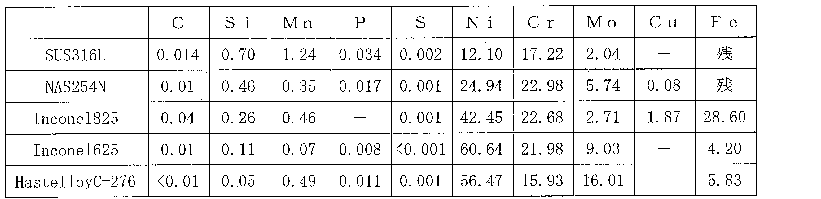
なお、表2の数値の単位は重量%である。
(まとめ)
フィルターエレメント80として耐食性材料を用いることにより、フィルターエレメントの腐食、および応力腐食割れの発生を抑制することができることが認められた。
フィルターエレメント80として耐食性材料を用いることにより、フィルターエレメントの腐食、および応力腐食割れの発生を抑制することができることが認められた。
本発明の一様態に係るトリクロロシラン製造装置では、金属シリコン粉体を用いてトリクロロシランを生成する反応装置と、前記反応装置により生成されたトリクロロシランと反応残渣とを含む反応生成物から前記反応残渣を除去するフィルター装置と、を備えたトリクロロシラン製造装置であって、前記フィルター装置は、耐食性材料から構成されたフィルターエレメントを備える。
また、本発明の一様態に係るトリクロロシラン製造装置では、前記耐食性材料は、モリブデンが1重量%以上含まれることが好ましい。
また、本発明の一様態に係るトリクロロシラン製造装置では、前記耐食性材料は、インコネル625またはハステロイであることが好ましい。
また、本発明の一様態に係るトリクロロシラン製造方法では、本発明の一様態に係るトリクロロシラン製造装置のいずれか一つに記載のトリクロロシラン製造装置を用いて、トリクロロシランを製造する工程を有することが好ましい。
本発明は、トリクロロシランの製造に利用することができる。
1 トリクロロシラン製造装置
2 反応装置
3 フィルター装置
10 反応容器
20 分散板
30 熱媒管
40 流動層
50 下部フィルター容器
60 上部フィルター容器
70 仕切板
80 フィルターエレメント
101 ガス供給口
102 反応生成物出口
103 フィルター装置入口
104 フィルター装置出口
105 残渣回収口
2 反応装置
3 フィルター装置
10 反応容器
20 分散板
30 熱媒管
40 流動層
50 下部フィルター容器
60 上部フィルター容器
70 仕切板
80 フィルターエレメント
101 ガス供給口
102 反応生成物出口
103 フィルター装置入口
104 フィルター装置出口
105 残渣回収口
Claims (4)
- 金属シリコン粉体を用いてトリクロロシランを生成する反応装置と、
前記反応装置により生成されたトリクロロシランと反応残渣とを含む反応生成物から前記反応残渣を除去するフィルター装置と、
を備えたトリクロロシラン製造装置であって、
前記フィルター装置は、耐食性材料から構成されたフィルターエレメントを備えることを特徴とするトリクロロシラン製造装置。 - 前記耐食性材料は、モリブデンが1重量%以上含まれることを特徴とする請求項1に記載のトリクロロシラン製造装置。
- 前記耐食性材料は、インコネル625またはハステロイであることを特徴とする請求項1または2に記載のトリクロロシラン製造装置。
- 請求項1~3のいずれか一項に記載のトリクロロシラン製造装置を用いて、トリクロロシランを製造する工程を有することを特徴とするトリクロロシランの製造方法。
Priority Applications (5)
| Application Number | Priority Date | Filing Date | Title |
|---|---|---|---|
| JP2019554323A JPWO2019098345A1 (ja) | 2017-11-20 | 2018-11-16 | トリクロロシラン製造装置およびトリクロロシランの製造方法 |
| CN201880060343.3A CN111108065A (zh) | 2017-11-20 | 2018-11-16 | 三氯硅烷制造装置以及三氯硅烷的制造方法 |
| US16/652,051 US20200277197A1 (en) | 2017-11-20 | 2018-11-16 | Trichlorosilane manufacturing apparatus, and method for manufacturing trichlorosilane |
| KR1020207007626A KR20200088276A (ko) | 2017-11-20 | 2018-11-16 | 트리클로로실란 제조 장치 및 트리클로로실란의 제조 방법 |
| EP18878799.8A EP3715329A4 (en) | 2017-11-20 | 2018-11-16 | APPARATUS FOR MANUFACTURING TRICHLOROSILANE AND METHOD FOR MANUFACTURING TRICHLOROSILANE |
Applications Claiming Priority (2)
| Application Number | Priority Date | Filing Date | Title |
|---|---|---|---|
| JP2017-223144 | 2017-11-20 | ||
| JP2017223144 | 2017-11-20 |
Publications (1)
| Publication Number | Publication Date |
|---|---|
| WO2019098345A1 true WO2019098345A1 (ja) | 2019-05-23 |
Family
ID=66539052
Family Applications (1)
| Application Number | Title | Priority Date | Filing Date |
|---|---|---|---|
| PCT/JP2018/042557 Ceased WO2019098345A1 (ja) | 2017-11-20 | 2018-11-16 | トリクロロシラン製造装置およびトリクロロシランの製造方法 |
Country Status (7)
| Country | Link |
|---|---|
| US (1) | US20200277197A1 (ja) |
| EP (1) | EP3715329A4 (ja) |
| JP (1) | JPWO2019098345A1 (ja) |
| KR (1) | KR20200088276A (ja) |
| CN (1) | CN111108065A (ja) |
| TW (1) | TWI752280B (ja) |
| WO (1) | WO2019098345A1 (ja) |
Cited By (3)
| Publication number | Priority date | Publication date | Assignee | Title |
|---|---|---|---|---|
| WO2021100286A1 (ja) * | 2019-11-21 | 2021-05-27 | 株式会社トクヤマ | フィルタ |
| JP7854026B1 (ja) | 2024-11-06 | 2026-04-30 | 株式会社トクヤマ | フィルタの洗浄方法及びフィルタの洗浄装置 |
| JP7854025B1 (ja) | 2024-11-06 | 2026-04-30 | 株式会社トクヤマ | フィルタの洗浄装置 |
Citations (7)
| Publication number | Priority date | Publication date | Assignee | Title |
|---|---|---|---|---|
| JPS4847500A (ja) * | 1971-10-21 | 1973-07-05 | ||
| JP2009292675A (ja) * | 2008-06-04 | 2009-12-17 | Sumitomo Chemical Co Ltd | シリコン又はハロゲン化シランの製造方法及び製造装置 |
| CN201643908U (zh) | 2009-12-01 | 2010-11-24 | 乐山乐电天威硅业科技有限责任公司 | 三氯氢硅合成气气固分离装置 |
| JP2011168443A (ja) * | 2010-02-18 | 2011-09-01 | Tokuyama Corp | トリクロロシランの製造方法 |
| JP2011184242A (ja) | 2010-03-09 | 2011-09-22 | Jnc Corp | クロロシランの製造装置 |
| CN102815706A (zh) * | 2012-08-10 | 2012-12-12 | 中国恩菲工程技术有限公司 | 一种三氯氢硅合成系统 |
| JP2013112589A (ja) * | 2011-11-30 | 2013-06-10 | Mitsubishi Materials Corp | トリクロロシラン製造方法及び製造装置 |
Family Cites Families (5)
| Publication number | Priority date | Publication date | Assignee | Title |
|---|---|---|---|---|
| JPH1072382A (ja) * | 1996-08-28 | 1998-03-17 | Asahi Glass Co Ltd | 1,1,1,3,3−ペンタフルオロプロパンの製造方法 |
| JP4462839B2 (ja) * | 2003-03-19 | 2010-05-12 | 株式会社キノテック・ソーラーエナジー | シリコンの製造装置及び製造方法 |
| US8778292B2 (en) * | 2009-05-12 | 2014-07-15 | Procedyne Corporation | Fluidized bed process for synthesizing trichlorosilane and a trichlorosilane synthesizer |
| CN104024159B (zh) * | 2011-10-18 | 2015-11-25 | 东亚合成株式会社 | 氯代聚硅烷的制造方法及流化床反应装置 |
| JP6439322B2 (ja) | 2014-08-27 | 2018-12-19 | 三菱自動車工業株式会社 | ハイブリッド車両の回生制御装置 |
-
2018
- 2018-11-16 KR KR1020207007626A patent/KR20200088276A/ko not_active Withdrawn
- 2018-11-16 EP EP18878799.8A patent/EP3715329A4/en not_active Withdrawn
- 2018-11-16 CN CN201880060343.3A patent/CN111108065A/zh active Pending
- 2018-11-16 TW TW107140847A patent/TWI752280B/zh active
- 2018-11-16 WO PCT/JP2018/042557 patent/WO2019098345A1/ja not_active Ceased
- 2018-11-16 JP JP2019554323A patent/JPWO2019098345A1/ja active Pending
- 2018-11-16 US US16/652,051 patent/US20200277197A1/en not_active Abandoned
Patent Citations (7)
| Publication number | Priority date | Publication date | Assignee | Title |
|---|---|---|---|---|
| JPS4847500A (ja) * | 1971-10-21 | 1973-07-05 | ||
| JP2009292675A (ja) * | 2008-06-04 | 2009-12-17 | Sumitomo Chemical Co Ltd | シリコン又はハロゲン化シランの製造方法及び製造装置 |
| CN201643908U (zh) | 2009-12-01 | 2010-11-24 | 乐山乐电天威硅业科技有限责任公司 | 三氯氢硅合成气气固分离装置 |
| JP2011168443A (ja) * | 2010-02-18 | 2011-09-01 | Tokuyama Corp | トリクロロシランの製造方法 |
| JP2011184242A (ja) | 2010-03-09 | 2011-09-22 | Jnc Corp | クロロシランの製造装置 |
| JP2013112589A (ja) * | 2011-11-30 | 2013-06-10 | Mitsubishi Materials Corp | トリクロロシラン製造方法及び製造装置 |
| CN102815706A (zh) * | 2012-08-10 | 2012-12-12 | 中国恩菲工程技术有限公司 | 一种三氯氢硅合成系统 |
Non-Patent Citations (1)
| Title |
|---|
| See also references of EP3715329A4 |
Cited By (4)
| Publication number | Priority date | Publication date | Assignee | Title |
|---|---|---|---|---|
| WO2021100286A1 (ja) * | 2019-11-21 | 2021-05-27 | 株式会社トクヤマ | フィルタ |
| JP6956928B1 (ja) * | 2019-11-21 | 2021-11-02 | 株式会社トクヤマ | フィルタ |
| JP7854026B1 (ja) | 2024-11-06 | 2026-04-30 | 株式会社トクヤマ | フィルタの洗浄方法及びフィルタの洗浄装置 |
| JP7854025B1 (ja) | 2024-11-06 | 2026-04-30 | 株式会社トクヤマ | フィルタの洗浄装置 |
Also Published As
| Publication number | Publication date |
|---|---|
| CN111108065A (zh) | 2020-05-05 |
| KR20200088276A (ko) | 2020-07-22 |
| EP3715329A1 (en) | 2020-09-30 |
| JPWO2019098345A1 (ja) | 2020-10-01 |
| EP3715329A4 (en) | 2021-07-28 |
| TWI752280B (zh) | 2022-01-11 |
| TW201922335A (zh) | 2019-06-16 |
| US20200277197A1 (en) | 2020-09-03 |
Similar Documents
| Publication | Publication Date | Title |
|---|---|---|
| US8956584B2 (en) | Production of polycrystalline silicon in substantially closed-loop processes that involve disproportionation operations | |
| WO2019098345A1 (ja) | トリクロロシラン製造装置およびトリクロロシランの製造方法 | |
| CN110167878B (zh) | 多晶硅制造方法 | |
| WO2012087628A2 (en) | Production of polycrystalline silicon by the thermal decomposition of dichlorosilane in a fluidized bed reactor | |
| EP2105410A1 (en) | Chlorosilanes purifying apparatus and chlorosilanes purifying method | |
| US20120100059A1 (en) | Production of Polycrystalline Silicon By The Thermal Decomposition of Trichlorosilane In A Fluidized Bed Reactor | |
| TWI403610B (zh) | 在實質上封閉迴路方法及系統中之多晶矽的製造 | |
| KR101309600B1 (ko) | 트리클로로실란 제조방법 | |
| US9394180B2 (en) | Production of polycrystalline silicon in substantially closed-loop systems | |
| TWI820056B (zh) | 反應裝置及三氯矽烷的製造方法 | |
| US8449848B2 (en) | Production of polycrystalline silicon in substantially closed-loop systems |
Legal Events
| Date | Code | Title | Description |
|---|---|---|---|
| 121 | Ep: the epo has been informed by wipo that ep was designated in this application |
Ref document number: 18878799 Country of ref document: EP Kind code of ref document: A1 |
|
| ENP | Entry into the national phase |
Ref document number: 2019554323 Country of ref document: JP Kind code of ref document: A |
|
| ENP | Entry into the national phase |
Ref document number: 2018878799 Country of ref document: EP Effective date: 20200622 |