WO2019098743A1 - 차량용 시트백 프레임 및 그의 제조방법 - Google Patents
차량용 시트백 프레임 및 그의 제조방법 Download PDFInfo
- Publication number
- WO2019098743A1 WO2019098743A1 PCT/KR2018/014083 KR2018014083W WO2019098743A1 WO 2019098743 A1 WO2019098743 A1 WO 2019098743A1 KR 2018014083 W KR2018014083 W KR 2018014083W WO 2019098743 A1 WO2019098743 A1 WO 2019098743A1
- Authority
- WO
- WIPO (PCT)
- Prior art keywords
- frame
- seat back
- cover sheet
- body frame
- vehicle
- Prior art date
- Legal status (The legal status is an assumption and is not a legal conclusion. Google has not performed a legal analysis and makes no representation as to the accuracy of the status listed.)
- Ceased
Links
Images


Classifications
-
- B—PERFORMING OPERATIONS; TRANSPORTING
- B60—VEHICLES IN GENERAL
- B60N—SEATS SPECIALLY ADAPTED FOR VEHICLES; VEHICLE PASSENGER ACCOMMODATION NOT OTHERWISE PROVIDED FOR
- B60N2/00—Seats specially adapted for vehicles; Arrangement or mounting of seats in vehicles
- B60N2/68—Seat frames
- B60N2/682—Joining means
-
- B—PERFORMING OPERATIONS; TRANSPORTING
- B60—VEHICLES IN GENERAL
- B60N—SEATS SPECIALLY ADAPTED FOR VEHICLES; VEHICLE PASSENGER ACCOMMODATION NOT OTHERWISE PROVIDED FOR
- B60N2/00—Seats specially adapted for vehicles; Arrangement or mounting of seats in vehicles
- B60N2/68—Seat frames
-
- B—PERFORMING OPERATIONS; TRANSPORTING
- B60—VEHICLES IN GENERAL
- B60N—SEATS SPECIALLY ADAPTED FOR VEHICLES; VEHICLE PASSENGER ACCOMMODATION NOT OTHERWISE PROVIDED FOR
- B60N2/00—Seats specially adapted for vehicles; Arrangement or mounting of seats in vehicles
- B60N2/58—Seat coverings
-
- B—PERFORMING OPERATIONS; TRANSPORTING
- B29—WORKING OF PLASTICS; WORKING OF SUBSTANCES IN A PLASTIC STATE IN GENERAL
- B29K—INDEXING SCHEME ASSOCIATED WITH SUBCLASSES B29B, B29C OR B29D, RELATING TO MOULDING MATERIALS OR TO MATERIALS FOR MOULDS, REINFORCEMENTS, FILLERS OR PREFORMED PARTS, e.g. INSERTS
- B29K2101/00—Use of unspecified macromolecular compounds as moulding material
- B29K2101/12—Thermoplastic materials
-
- B—PERFORMING OPERATIONS; TRANSPORTING
- B60—VEHICLES IN GENERAL
- B60N—SEATS SPECIALLY ADAPTED FOR VEHICLES; VEHICLE PASSENGER ACCOMMODATION NOT OTHERWISE PROVIDED FOR
- B60N2/00—Seats specially adapted for vehicles; Arrangement or mounting of seats in vehicles
- B60N2/68—Seat frames
- B60N2/686—Panel like structures
-
- B—PERFORMING OPERATIONS; TRANSPORTING
- B60—VEHICLES IN GENERAL
- B60N—SEATS SPECIALLY ADAPTED FOR VEHICLES; VEHICLE PASSENGER ACCOMMODATION NOT OTHERWISE PROVIDED FOR
- B60N2/00—Seats specially adapted for vehicles; Arrangement or mounting of seats in vehicles
- B60N2/68—Seat frames
- B60N2/682—Joining means
- B60N2002/684—Joining means the back rest being mounted or joined with an easy attachment system to the seat
-
- B—PERFORMING OPERATIONS; TRANSPORTING
- B60—VEHICLES IN GENERAL
- B60N—SEATS SPECIALLY ADAPTED FOR VEHICLES; VEHICLE PASSENGER ACCOMMODATION NOT OTHERWISE PROVIDED FOR
- B60N2205/00—General mechanical or structural details
- B60N2205/30—Seat or seat parts characterised by comprising plural parts or pieces
- B60N2205/35—Seat, bench or back-rests being split laterally in two or more parts
Definitions
- the present invention relates to a vehicle seat back frame and a manufacturing method thereof, and more particularly, to a vehicle seat back frame in which a body frame and a reinforcing agent are formed by a thermoplastic fiber reinforced composite material and the cover sheet is joined to the body frame, To a method of manufacturing a seat back frame for a vehicle in which a cover sheet is vacuum-adsorbed and pressurized to be coupled to a body frame.
- a seat for a vehicle is important in terms of ride comfort and safety, and absorbs shocks or vibrations transmitted when the vehicle is traveling to provide comfort to passengers.
- the seat back frame is a rigid structure provided inside a seat of a vehicle, and is a basic structure of a seat back that helps a user to take a comfortable and stable posture.
- a seat back frame of a passenger car (hereinafter briefly referred to as a " seat back frame ") may cause a breakage or deformation of the seat due to passenger behavior when the automobile suddenly stops or collides, have.
- the seat back frame stipulates that there will be no breakage of the seat back due to inertia due to the self weight of the seat back in the event of a vehicle collision, a collision, or a sudden stop, a permanent deformation and breakage of the seat back when pulled or pushed by a constant force It must satisfy the regulations.
- the seat back frame according to the conventional method is manufactured using a single material such as steel.
- a single material such as steel.
- One aspect of the present invention is to provide a seat back frame for a vehicle integrated with a slim body, which can omit a board that is further coupled to the seat back frame as a result of being made lightweight while maintaining the rigidity and strength as the steel frame, .
- Another aspect of the present invention is to provide a method for bonding a reinforcing agent to a body frame made of a thermoplastic fiber reinforced composite material by an injection molding method and bonding the heated cover sheet to the body frame under vacuum, To provide a method of manufacturing a seat back frame.
- a vehicle seat back frame includes a frame body made of a thermoplastic fiber reinforced composite material, a reinforcing agent coupled to the inside of the frame body, and a cover sheet coupled to the outside of the frame body.
- the reinforcing agent may include a first reinforcing portion extending in the transverse direction of the frame body, a second reinforcing portion located at both sides of the frame body, the first reinforcing portion being connected to the first reinforcing portion, A third reinforcing portion formed to extend in the longitudinal direction of the body and connected to the first reinforcing portion and a fourth reinforcing portion formed on an outer peripheral portion of the frame body and connected to the second reinforcing portion and the third reinforcing portion.
- the reinforcing agent may further include a headrest coupling portion connected to the second coupling portion and having an insertion hole to which the headrest is coupled.
- thermoplastic fiber reinforced composite material may be made of a composite resin including a continuous fiber reinforced thermoplastic (CFT) or a continuous fiber reinforced thermoplastic resin (CFT).
- CFT continuous fiber reinforced thermoplastic
- CFT continuous fiber reinforced thermoplastic resin
- the reinforcing agent may be made of a material including a long fiber reinforced thermoplastic (LFT) or a long fiber reinforced thermoplastic resin (LFT).
- LFT long fiber reinforced thermoplastic
- LFT long fiber reinforced thermoplastic resin
- the cover sheet may be made of TPO (Thermo Plastic Olefin) material.
- a method for manufacturing a seat back frame for a vehicle includes a body frame forming step of forming a body frame using a thermoplastic fiber reinforced composite material, a reinforcing part forming step of injecting and molding a reinforcing part inside the body frame, And a cover sheet attaching step of attaching the cover sheet to the outside of the body frame.
- the cover sheet attaching step is a press press forming step for selectively preheating the cover sheet and the body frame, and pressing the cover sheet and the body frame to press the cover sheet.
- the cover sheet is vacuum-absorbed through the lower mold while the body frame is seated on the lower mold, and the cover sheet is pressed onto the body frame, To the cover sheet.
- the body frame is placed in a lower mold having a suction hole, and the cover frame is brought into contact with the body frame in a state in which the body frame is in close contact with the lower mold through the suction hole And the cover sheet is pressed against the body frame by the upper mold.
- the thermoplastic fiber reinforced composite material may be composed of a composite resin including a continuous fiber reinforced thermoplastic (CFT) or a continuous fiber reinforced thermoplastic resin (CFT).
- CFT continuous fiber reinforced thermoplastic
- CFT continuous fiber reinforced thermoplastic resin
- the reinforcing agent may be made of a material including a long fiber reinforced thermoplastic (LFT) or a long fiber reinforced thermoplastic resin (LFT).
- LFT long fiber reinforced thermoplastic
- LFT long fiber reinforced thermoplastic resin
- the cover sheet may be made of TPO (Thermo Plastic Olefin) material.
- the board which is further coupled to the seat back frame can be omitted, and a slim, .
- a method of manufacturing a seat back frame for a vehicle having improved bonding strength and increased commerciality can be obtained by attaching a cover sheet to a body frame using a vacuum suction method.
- FIG. 1 is a schematic view showing a seat back frame for a vehicle according to an embodiment of the present invention.
- FIG. 2 is a flowchart schematically showing a manufacturing method of the seat back frame for a vehicle shown in Fig.
- FIG. 3 is a process state diagram schematically showing an embodiment of the cover sheet attaching step shown in FIG. 2.
- FIG. 3 is a process state diagram schematically showing an embodiment of the cover sheet attaching step shown in FIG. 2.
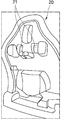
- Fig. 4 is a schematic view showing the lower mold shown in Fig. 3.
- Fig. 4 is a schematic view showing the lower mold shown in Fig. 3.
- FIG. 1 is a schematic view showing a seat back frame for a vehicle according to an embodiment of the present invention.
- the vehicle seatback frame 1000 includes a frame body 1100, a reinforcing agent 1200, and a cover sheet 1300.
- the frame body 1100 is made of a thermoplastic fiber reinforced composite material, and the thermoplastic fiber reinforced composite material is a composite resin including a continuous fiber reinforced thermoplastic (CFT) or a continuous fiber reinforced thermoplastic resin (CFT) Lt; / RTI >
- CFT continuous fiber reinforced thermoplastic
- CFT continuous fiber reinforced thermoplastic resin
- the reinforcing agent 1200 is injected into a thermoplastic fiber reinforced composite material and bonded to the inside of the frame body 1100.
- the reinforcing agent 1200 is for providing rigidity and strength to the frame body 1100 and is made of a material including a long fiber reinforced thermoplastic (LFT) or a long fiber reinforced thermoplastic resin (LFT) .
- LFT long fiber reinforced thermoplastic
- LFT long fiber reinforced thermoplastic resin
- the thermoplastic resin contained in the long fiber-reinforced thermoplastic resin may include at least one selected from the group consisting of a polypropylene resin, a polyethylene resin, a polyamide resin, a polyester resin, a polyphenylene sulfide resin, have.
- the reinforcing agent 1200 includes a headrest joining portion 1210, a first reinforcing portion 1220, a second reinforcing portion 1230, a third reinforcing portion 1240 and a fourth reinforcing portion 1250.
- the headrest joining portion 1210 is formed with a coupling hole 1211 to which the headrest is engaged.
- the one reinforcing portion 1220 is for restricting the vehicle seatback frame 1000 from being bent in the lateral direction and is formed to extend in the lateral direction of the frame body 1100.
- the second reinforcing portion 1230 is provided to complement the strength of both side portions of the vehicle seatback frame 1000 and is positioned at both sides of the frame body 1100 and one reinforcing portion 1220 is connected.
- the third reinforcing portion 1240 is formed to extend in the longitudinal direction of the frame body 1100 and is formed to be connected to the one reinforcing portion 1220 and the headrest engaging portion 1210.
- the fourth reinforcing portion 1250 is provided on the outer peripheral portion of the frame body 1100 and is formed as an outer frame for supplementing the strength of the outer peripheral portion of the vehicle seatback frame 1000.
- the second reinforcing portion 1230 and the third reinforcing portion 1240 are connected to the fourth reinforcing portion 1250.
- cover sheet 1300 is coupled to the outside of the frame body 1100.
- the cover sheet 1300 may be made of TPO (Thermo Plastic Olefin) material, which is not damaged by heat.
- cover sheet can be made of a red structure including a surface treatment layer, a primer layer, a sheet layer and a backside primer layer.
- cover sheet may be composed of a surface treatment layer and a red structure including a primer layer, a sheet layer, a PP or TPO FOAM layer.
- the cover sheet enhances the embossing force, and includes excellent heat resistance and low temperature characteristics.
- the cover sheet may include a polystyrene-based copolymer and an ethylene vinyl acetate-based copolymer, and the ethylene vinyl acetate-based copolymer may contain at least 50% by weight of vinyl acetate.
- the polystyrene-based copolymer may be selected from the group consisting of styrene- (ethylene / buthylene) -styrene block copolymer (SEBS), crystalline block- (ethylene / buthylene) -crystalline block copolymer (CEBC), hydrogenated styrene butadiene rubber (Ethylene-ethylene / propylene) -block polystyrene (SEEPS), SEEPSOH (polystyrene-block-poly (ethylene-ethylene / propylene) (polystyrene-block-poly (ethylene / propylene) -block-polystyrene) SEP (polystyrene block copolymer).
- SEBS styrene- (ethylene / buthylene) -styrene block copolymer
- CEBC crystalline block- (ethylene / buthylene) -crystalline block copolymer
- SEEPS
- the weight average molecular weight of the polystyrene-based copolymer may be 50,000 to 300,000.
- the weight average molecular weight of the ethylene vinyl acetate-based copolymer may be 100,000 to 400,000.
- the polystyrene type copolymer and the ethylene vinyl acetate type copolymer may be contained in a weight ratio of 1: 9 to 9: 1.
- the vehicle seat back frame 1000 is joined to the inside of the seat back frame 1000 with the reinforcing agent 1200, and the cover sheet 1300 is coupled to the outside.
- FIG. 2 is a flowchart schematically showing a manufacturing method of the seat back frame for a vehicle shown in Fig.
- the method for manufacturing a seat back frame for a vehicle includes a body frame forming step (S1100), a reinforcing portion forming step (S1200), and a cover sheet attaching step (S1300).
- the body frame forming step S1100 is a step of molding a body frame using a thermoplastic fiber reinforced composite material.
- the thermoplastic fiber reinforced composite material can be made of a composite material including a continuous fiber reinforced thermoplastic (CFT) or a continuous fiber reinforced thermoplastic resin (CFT).
- the reinforcing part forming step (S1200) is a step of injection-molding the reinforcing part in the body frame.
- the reinforcing portion may be made of a material including a long fiber reinforced thermoplastic (LFT) or a long fiber reinforced thermoplastic resin (LFT) to provide rigidity and strength to the frame body.
- LFT long fiber reinforced thermoplastic
- LFT long fiber reinforced thermoplastic resin
- the thermoplastic resin contained in the long fiber-reinforced thermoplastic resin may include at least one selected from the group consisting of a polypropylene resin, a polyethylene resin, a polyamide resin, a polyester resin, a polyphenylene sulfide resin, have.
- the reinforcing portion can be injection-molded into two types of materials on the body frame, and thus can be realized in various shapes.
- the cover sheet attaching step S1300 is a step of attaching the cover sheet to the outside of the body frame to which the reinforcing part is coupled to the inside of the body frame.
- cover sheet engaging step (S1300) may be a pressing and pressing step which is a press-pressing step.
- cover sheet and the body frame are selectively preheated, and the cover sheet and the body frame are pressed to the outside of the body frame, thereby joining the cover sheet to the body frame.
- the cover sheet when the cover sheet is coupled to the body frame, the cover sheet can be coupled to the body frame using a vacuum molding method in which the cover sheet is pulled toward the mold.
- the cover sheet can be more efficiently coupled to the body frame having various bent portions.
- FIG. 3 is a process state diagram schematically showing an embodiment of the cover sheet attaching step shown in FIG. 2.
- FIG. 3 is a process state diagram schematically showing an embodiment of the cover sheet attaching step shown in FIG. 2.
- the cover sheet holder 40 to which the cover sheet is attached, is placed between the upper mold 10 and the lower mold 20 for press-molding.
- the preheater 30 is positioned between the cover sheet holder 40 and the lower mold 20 so as to face each other.
- the lower mold 20 is raised, and the cover sheet coupled to the cover sheet holder 40 is coupled to the body frame while the upper mold 10 is lowered.
- a suction hole 21 is formed in the lower mold 20 as shown in FIG. 4, and a hole (not shown) corresponding to the suction hole 21 is formed in the body frame.
- the cover sheet When the body frame is seated on the lower mold 20, the cover sheet is brought into tight contact with the body frame through the suction hole 21, and the cover sheet is joined to the body frame.
- the cover sheet can be joined to the outer circumferential portion of the body frame without a poor connection of the cover sheet.
- suction holes are formed on the upper portion, and a plurality of suction holes may be formed to correspond to the edges of the body frame.
Landscapes
- Engineering & Computer Science (AREA)
- Aviation & Aerospace Engineering (AREA)
- Transportation (AREA)
- Mechanical Engineering (AREA)
- Seats For Vehicles (AREA)
- Injection Moulding Of Plastics Or The Like (AREA)
- Chair Legs, Seat Parts, And Backrests (AREA)
Abstract
Description
Claims (13)
- 열가소성 섬유강화복합소재로 이루어진 프레임 바디;상기 프레임 바디의 내측에 결합된 보강제; 및상기 프레임 바디의 외측에 결합된 커버시트를 포함하는차량용 시트백 프레임.
- 제 1 항에 있어서,상기 보강제는상기 프레임 바디의 횡방향으로 연장된 제1 보강부와,상기 프레임 바디의 양측부에 위치되고, 상기 제1 보강부가 연결된 제2 보강부와,상기 프레임 바디의 종방향으로 연장되도록 형성되고, 상기 제1 보강부가 연결된 상기 제3 보강부와,상기 프레임 바디의 외주부에 형성되고, 제2 보강부와 제3 보강부가 연결된 제4 보강부를 포함하는차량용 시트백 프레임.
- 제 2 항에 있어서,상기 보강제는상기 제2 결합부와 연결되고, 헤드레스트가 결합되는 삽입공이 형성된 헤드레스트 결합부를 더 포함하는차량용 시트백 프레임.
- 제 1 항에 있어서,상기 열가소성 섬유강화 복합소재는연속섬유 강화 열가소성수지(CFT: Continuous Fiber reinforced Thermoplastic) 또는 연속섬유 강화 열가소성수지(CFT)를 포함하는 복합수지로 이루어지는차량용 시트백 프레임.
- 제 1 항에 있어서,상기 보강제는장섬유 강화 열가소성 수지(LFT: Long Fiber reinforced Thermoplastic) 또는 장섬유 강화 열가소성 수지(LFT)를 포함하는 소재로 이루어지는차량용 시트백 프레임.
- 제 1 항에 있어서,상기 커버시트는TPO(ThermoPlastic Olefin)소재로 이루어진차량용 시트백 프레임.
- 열가소성 섬유강화복합소재를 이용하여 바디 프레임 형상으로 성형하는 바디 프레임 성형단계;상기 바디 프레임의 내측에 보강부를 사출성형하는 보강부 형성단계; 및상기 바디 프레임의 외측에 커버시트를 결합시키는 커버시트 결합단계를 포함하는차량용 시트백 프레임 제조방법.
- 제 7 항에 있어서,상기 커버시트 결합단계는상기 커버시트와 상기 바디 프레임을 선택적으로 예열하고, 하부 금형에 상기 바디 프레임을 안착시킨 상태에서 상부 금형으로 가압하여 상기 바디 프레임에 상기 커버시트를 결합시키는 프레스 가압 성형단계인차량용 시트백 프레임 제조방법.
- 제 8 항에 있어서,상기 커버시트 결합단계는상기 바디 프레임을 상기 하부 금형에 안착시킨 상태에서 상기 커버시트를 상기 하부 금형을 통해 진공흡착하여 상기 바디 프레임에 밀착시키고, 상부 금형으로 가압하여 상기 바디 프레임에 상기 커버시트를 결합시키는차량용 시트백 프레임 제조방법.
- 제 9 항에 있어서,상기 바디 프레임에는 홀이 형성되고, 상기 하부 금형에는 상기 홀에 대응되는 흡입홀이 형성되고, 상기 흡입홀을 통해 상기 시트 커버를 상기 바디 프레임에 밀착시킨 상태에서 상부 금형으로 상기 커버시트를 가압하여 상기 바디 프레임에 상기 커버시트를 결합시키는차량용 시트백 프레임 제조방법.
- 제 7 항에 있어서,상기 열가소성 섬유강화 복합소재는연속섬유 강화 열가소성수지(CFT: Continuous Fiber reinforced Thermoplastic) 또는 연속섬유 강화 열가소성수지(CFT)를 포함하는 복합수지로 이루어지는차량용 시트백 프레임 제조방법.
- 제 7 항에 있어서,상기 보강제는장섬유 강화 열가소성 수지(LFT: Long Fiber reinforced Thermoplastic) 또는 장섬유 강화 열가소성 수지(LFT)를 포함하는 소재로 이루어지는차량용 시트백 프레임 제조방법.
- 제 7 항에 있어서,상기 커버시트는TPO(ThermoPlastic Olefin)소재로 이루어진차량용 시트백 프레임 제조방법.
Priority Applications (2)
| Application Number | Priority Date | Filing Date | Title |
|---|---|---|---|
| CN201880074501.0A CN111356610B (zh) | 2017-11-16 | 2018-11-16 | 车辆用座椅靠背框架及其制造方法 |
| US16/764,877 US11318870B2 (en) | 2017-11-16 | 2018-11-16 | Seat back frame for vehicle and manufacturing method thereof |
Applications Claiming Priority (2)
| Application Number | Priority Date | Filing Date | Title |
|---|---|---|---|
| KR1020170152736A KR102200966B1 (ko) | 2017-11-16 | 2017-11-16 | 차량용 시트백 프레임 및 그의 제조방법 |
| KR10-2017-0152736 | 2017-11-16 |
Publications (1)
| Publication Number | Publication Date |
|---|---|
| WO2019098743A1 true WO2019098743A1 (ko) | 2019-05-23 |
Family
ID=66538744
Family Applications (1)
| Application Number | Title | Priority Date | Filing Date |
|---|---|---|---|
| PCT/KR2018/014083 Ceased WO2019098743A1 (ko) | 2017-11-16 | 2018-11-16 | 차량용 시트백 프레임 및 그의 제조방법 |
Country Status (4)
| Country | Link |
|---|---|
| US (1) | US11318870B2 (ko) |
| KR (1) | KR102200966B1 (ko) |
| CN (1) | CN111356610B (ko) |
| WO (1) | WO2019098743A1 (ko) |
Cited By (3)
| Publication number | Priority date | Publication date | Assignee | Title |
|---|---|---|---|---|
| US20220118894A1 (en) * | 2018-12-29 | 2022-04-21 | Sabic Global Technologies B.V. | Plastic seating frame for electrical vehicle |
| US20220227266A1 (en) * | 2021-01-19 | 2022-07-21 | Faurecia Sièges d'Automobile | Vehicle seat backrest |
| US20230211712A1 (en) * | 2020-05-28 | 2023-07-06 | Ts Tech Co., Ltd. | Cushion support member structure and vehicle seat |
Families Citing this family (2)
| Publication number | Priority date | Publication date | Assignee | Title |
|---|---|---|---|---|
| KR102642466B1 (ko) * | 2019-11-15 | 2024-02-29 | (주)엘엑스하우시스 | 차량용 시트백 커버 및 그 제조방법 |
| KR102444345B1 (ko) * | 2020-12-08 | 2022-09-19 | (주)풍진솔루션 | 차량용 시트백 제조시스템 |
Citations (5)
| Publication number | Priority date | Publication date | Assignee | Title |
|---|---|---|---|---|
| KR100217510B1 (ko) * | 1997-06-13 | 1999-09-01 | 유 희 춘 | 열가소성 수지가 첨가된 자동차 내장재의 제조방법 |
| KR101306296B1 (ko) * | 2011-04-26 | 2013-09-09 | 덕양산업 주식회사 | 올레핀계 스프레이형 접착제를 이용한 자동차용 내장부품 진공 성형방법 및 그에 따라 제조된 자동차용 내장부품 |
| KR101643177B1 (ko) * | 2014-09-05 | 2016-07-28 | 한화첨단소재 주식회사 | 백커버 일체형 차량용 시트 프레임 |
| KR101714833B1 (ko) * | 2014-04-28 | 2017-03-23 | (주)엘지하우시스 | 시트 백 프레임 |
| KR101738058B1 (ko) * | 2016-01-13 | 2017-05-19 | 현대자동차주식회사 | 차량용 시트백프레임 구조 및 그 제조방법 |
Family Cites Families (20)
| Publication number | Priority date | Publication date | Assignee | Title |
|---|---|---|---|---|
| US4123105A (en) * | 1975-10-29 | 1978-10-31 | Interroyal Corporation | Chair construction |
| WO2004024424A1 (de) * | 2002-09-15 | 2004-03-25 | Rcc Regional Compact Car Ag | Strukturbauteil aus faserverstärktem thermoplastischem kunststoff |
| US7128373B2 (en) | 2002-09-27 | 2006-10-31 | Dow Global Technologies, Inc. | Seating system and method of forming same |
| EP2046601A2 (en) * | 2006-07-21 | 2009-04-15 | Basf Se | Modular seat back assembly |
| DE102006051566A1 (de) | 2006-11-02 | 2008-05-08 | Volkswagen Ag | Rückenlehne |
| WO2009154909A1 (en) * | 2008-05-28 | 2009-12-23 | Dow Global Technologies Inc. | Improved vehicular seat back assembly |
| WO2013008752A1 (ja) * | 2011-07-13 | 2013-01-17 | 東レ株式会社 | 背もたれ用フレーム構造体およびその製造方法 |
| JP5728349B2 (ja) * | 2011-09-21 | 2015-06-03 | 日本発條株式会社 | 車両用シート |
| EP2819824B1 (de) * | 2012-03-02 | 2016-12-28 | Johnson Controls GmbH | Verfahren zur herstellung einer sitzlehnenrückwand |
| WO2014024936A1 (ja) * | 2012-08-09 | 2014-02-13 | テイ・エス テック株式会社 | 車両用シート |
| EP2956334A1 (en) | 2013-02-18 | 2015-12-23 | Faurecia Automotive Seating, LLC | Seat back for vehicle seat |
| JP6095434B2 (ja) * | 2013-03-22 | 2017-03-15 | 日本発條株式会社 | 車両用シート |
| WO2015058077A1 (en) * | 2013-10-18 | 2015-04-23 | Johnson Controls Technology Company | Reinforcement for vehicle seat structures and components |
| KR20150144050A (ko) * | 2014-06-16 | 2015-12-24 | (주)엘지하우시스 | 자동차 시트백의 외장보드 제조방법 |
| JP6485210B2 (ja) | 2015-05-19 | 2019-03-20 | トヨタ紡織株式会社 | 乗物用シート |
| KR101894130B1 (ko) * | 2015-11-13 | 2018-10-05 | (주)엘지하우시스 | Cft 프리포밍 인서트 사출 성형 시트 백 프레임 |
| JP6332260B2 (ja) * | 2015-12-25 | 2018-05-30 | トヨタ自動車株式会社 | 車両用骨格部材の補強構造 |
| EP3202618A1 (en) | 2016-02-05 | 2017-08-09 | B/E Aerospace, Inc. | Passenger seatback assembly with thermoplastic elements |
| JP6638679B2 (ja) * | 2017-03-23 | 2020-01-29 | テイ・エス テック株式会社 | シートバックフレームの補強構造 |
| US11007911B2 (en) * | 2017-03-23 | 2021-05-18 | Ts Tech Co., Ltd. | Seat back structure |
-
2017
- 2017-11-16 KR KR1020170152736A patent/KR102200966B1/ko active Active
-
2018
- 2018-11-16 CN CN201880074501.0A patent/CN111356610B/zh active Active
- 2018-11-16 US US16/764,877 patent/US11318870B2/en active Active
- 2018-11-16 WO PCT/KR2018/014083 patent/WO2019098743A1/ko not_active Ceased
Patent Citations (5)
| Publication number | Priority date | Publication date | Assignee | Title |
|---|---|---|---|---|
| KR100217510B1 (ko) * | 1997-06-13 | 1999-09-01 | 유 희 춘 | 열가소성 수지가 첨가된 자동차 내장재의 제조방법 |
| KR101306296B1 (ko) * | 2011-04-26 | 2013-09-09 | 덕양산업 주식회사 | 올레핀계 스프레이형 접착제를 이용한 자동차용 내장부품 진공 성형방법 및 그에 따라 제조된 자동차용 내장부품 |
| KR101714833B1 (ko) * | 2014-04-28 | 2017-03-23 | (주)엘지하우시스 | 시트 백 프레임 |
| KR101643177B1 (ko) * | 2014-09-05 | 2016-07-28 | 한화첨단소재 주식회사 | 백커버 일체형 차량용 시트 프레임 |
| KR101738058B1 (ko) * | 2016-01-13 | 2017-05-19 | 현대자동차주식회사 | 차량용 시트백프레임 구조 및 그 제조방법 |
Cited By (6)
| Publication number | Priority date | Publication date | Assignee | Title |
|---|---|---|---|---|
| US20220118894A1 (en) * | 2018-12-29 | 2022-04-21 | Sabic Global Technologies B.V. | Plastic seating frame for electrical vehicle |
| US11904746B2 (en) * | 2018-12-29 | 2024-02-20 | Sabic Global Technologies B.V. | Plastic seating frame for electrical vehicle |
| US20230211712A1 (en) * | 2020-05-28 | 2023-07-06 | Ts Tech Co., Ltd. | Cushion support member structure and vehicle seat |
| US12344142B2 (en) * | 2020-05-28 | 2025-07-01 | Ts Tech Co., Ltd. | Cushion support member structure and vehicle seat |
| US20220227266A1 (en) * | 2021-01-19 | 2022-07-21 | Faurecia Sièges d'Automobile | Vehicle seat backrest |
| US11975636B2 (en) * | 2021-01-19 | 2024-05-07 | Faurecia Sièges d'Automobile | Vehicle seat backrest |
Also Published As
| Publication number | Publication date |
|---|---|
| US11318870B2 (en) | 2022-05-03 |
| KR20190055904A (ko) | 2019-05-24 |
| CN111356610B (zh) | 2022-07-22 |
| US20200324673A1 (en) | 2020-10-15 |
| KR102200966B1 (ko) | 2021-01-11 |
| CN111356610A (zh) | 2020-06-30 |
Similar Documents
| Publication | Publication Date | Title |
|---|---|---|
| WO2019098743A1 (ko) | 차량용 시트백 프레임 및 그의 제조방법 | |
| CN101143578B (zh) | 车辆座椅侧面的气袋组合装置 | |
| US4816313A (en) | Resin product with main resin body and soft resin covering part | |
| EP2783918A1 (en) | Resin panel and forming method | |
| US20050091935A1 (en) | Window assembly and method for manufacturing the same | |
| WO2016093640A1 (ko) | 이경도를 갖는 일체발포형 헤드레스트 및 그 제조방법 | |
| WO2016182173A1 (ko) | 섬유강화복합소재를 이용한 인서트 사출 성형 방법 및 이를 이용한 사출 성형품 | |
| WO2017082693A1 (ko) | Cft 프리포밍 인서트 사출 성형 시트 백 프레임 | |
| JP3872597B2 (ja) | 自動車用内装部品 | |
| WO2017061721A1 (ko) | 자동차 인테리어 시트, 이를 이용한 자동차 내장재의 제조방법 및 이 제조방법에 의해 제조된 자동차 내장재 | |
| JPH1044188A (ja) | 樹脂製エアバッグの製造方法及び樹脂製エアバッグ | |
| WO2019098741A1 (ko) | 원단 일체형 차량용 시트백 프레임 및 그의 제조방법 | |
| US20200016995A1 (en) | Motor vehicle floor | |
| WO2023113121A1 (ko) | Lwrt를 이용한 시트백 보드 | |
| WO2022108138A1 (ko) | 자동차용 흡음재의 성형방법 | |
| US11904746B2 (en) | Plastic seating frame for electrical vehicle | |
| KR102200970B1 (ko) | 차량용 시트백 프레임 및 그의 제조방법 | |
| WO2020111612A1 (ko) | 밀폐결합구조의 크래시패드 덕트조립체 | |
| US20020121714A1 (en) | Automobile interior components that satisfy impact standards and a method for manufacturing the same | |
| JPS5920630A (ja) | モ−ルデイングの製造方法 | |
| JP2004148905A (ja) | 自動車用内装部品及びその製造方法 | |
| WO2020122306A1 (ko) | 시트프레임 어셈블리 및 그 제조방법 | |
| WO2023003257A1 (ko) | 필러 고함량 폴리페닐렌설파이드 복합 수지 및 이를 이용한 성형품 | |
| JP2006347273A (ja) | 自動車用内装部品及びその製造方法 | |
| WO2010074476A1 (en) | Monolithic expanded polypropylene steering wheel, manufacturing apparatus and method thereof |
Legal Events
| Date | Code | Title | Description |
|---|---|---|---|
| 121 | Ep: the epo has been informed by wipo that ep was designated in this application |
Ref document number: 18878891 Country of ref document: EP Kind code of ref document: A1 |
|
| NENP | Non-entry into the national phase |
Ref country code: DE |
|
| 122 | Ep: pct application non-entry in european phase |
Ref document number: 18878891 Country of ref document: EP Kind code of ref document: A1 |
|
| 32PN | Ep: public notification in the ep bulletin as address of the adressee cannot be established |
Free format text: NOTING OF LOSS OF RIGHTS PURSUANT TO RULE 112(1) EPC (EPO FORM 1205A DATED 21/01/2021) |
|
| 122 | Ep: pct application non-entry in european phase |
Ref document number: 18878891 Country of ref document: EP Kind code of ref document: A1 |