WO2019102129A1 - Outil de coupe électrique à arrêt d'urgence automatique - Google Patents
Outil de coupe électrique à arrêt d'urgence automatique Download PDFInfo
- Publication number
- WO2019102129A1 WO2019102129A1 PCT/FR2018/052914 FR2018052914W WO2019102129A1 WO 2019102129 A1 WO2019102129 A1 WO 2019102129A1 FR 2018052914 W FR2018052914 W FR 2018052914W WO 2019102129 A1 WO2019102129 A1 WO 2019102129A1
- Authority
- WO
- WIPO (PCT)
- Prior art keywords
- impedance
- monitoring
- cutting
- electrical
- cutting member
- Prior art date
- Legal status (The legal status is an assumption and is not a legal conclusion. Google has not performed a legal analysis and makes no representation as to the accuracy of the status listed.)
- Ceased
Links
Classifications
-
- B—PERFORMING OPERATIONS; TRANSPORTING
- B26—HAND CUTTING TOOLS; CUTTING; SEVERING
- B26B—HAND-HELD CUTTING TOOLS NOT OTHERWISE PROVIDED FOR
- B26B15/00—Hand-held shears with motor-driven blades
-
- B—PERFORMING OPERATIONS; TRANSPORTING
- B26—HAND CUTTING TOOLS; CUTTING; SEVERING
- B26D—CUTTING; DETAILS COMMON TO MACHINES FOR PERFORATING, PUNCHING, CUTTING-OUT, STAMPING-OUT OR SEVERING
- B26D7/00—Details of apparatus for cutting, cutting-out, stamping-out, punching, perforating, or severing by means other than cutting
- B26D7/22—Safety devices specially adapted for cutting machines
- B26D7/24—Safety devices specially adapted for cutting machines arranged to disable the operating means for the cutting member
-
- A—HUMAN NECESSITIES
- A01—AGRICULTURE; FORESTRY; ANIMAL HUSBANDRY; HUNTING; TRAPPING; FISHING
- A01G—HORTICULTURE; CULTIVATION OF VEGETABLES, FLOWERS, RICE, FRUIT, VINES, HOPS OR SEAWEED; FORESTRY; WATERING
- A01G3/00—Cutting implements specially adapted for horticultural purposes; Delimbing standing trees
- A01G3/02—Secateurs; Flower or fruit shears
- A01G3/033—Secateurs; Flower or fruit shears having motor-driven blades
- A01G3/037—Secateurs; Flower or fruit shears having motor-driven blades the driving means being an electric motor
-
- A—HUMAN NECESSITIES
- A01—AGRICULTURE; FORESTRY; ANIMAL HUSBANDRY; HUNTING; TRAPPING; FISHING
- A01G—HORTICULTURE; CULTIVATION OF VEGETABLES, FLOWERS, RICE, FRUIT, VINES, HOPS OR SEAWEED; FORESTRY; WATERING
- A01G3/00—Cutting implements specially adapted for horticultural purposes; Delimbing standing trees
- A01G3/08—Other tools for pruning, branching or delimbing standing trees
- A01G3/085—Motor-driven saws for pruning or branching
-
- B—PERFORMING OPERATIONS; TRANSPORTING
- B26—HAND CUTTING TOOLS; CUTTING; SEVERING
- B26D—CUTTING; DETAILS COMMON TO MACHINES FOR PERFORATING, PUNCHING, CUTTING-OUT, STAMPING-OUT OR SEVERING
- B26D7/00—Details of apparatus for cutting, cutting-out, stamping-out, punching, perforating, or severing by means other than cutting
- B26D7/22—Safety devices specially adapted for cutting machines
-
- F—MECHANICAL ENGINEERING; LIGHTING; HEATING; WEAPONS; BLASTING
- F16—ENGINEERING ELEMENTS AND UNITS; GENERAL MEASURES FOR PRODUCING AND MAINTAINING EFFECTIVE FUNCTIONING OF MACHINES OR INSTALLATIONS; THERMAL INSULATION IN GENERAL
- F16P—SAFETY DEVICES IN GENERAL; SAFETY DEVICES FOR PRESSES
- F16P3/00—Safety devices acting in conjunction with the control or operation of a machine; Control arrangements requiring the simultaneous use of two or more parts of the body
- F16P3/12—Safety devices acting in conjunction with the control or operation of a machine; Control arrangements requiring the simultaneous use of two or more parts of the body with means, e.g. feelers, which in case of the presence of a body part of a person in or near the danger zone influence the control or operation of the machine
-
- G—PHYSICS
- G01—MEASURING; TESTING
- G01V—GEOPHYSICS; GRAVITATIONAL MEASUREMENTS; DETECTING MASSES OR OBJECTS; TAGS
- G01V3/00—Electric or magnetic prospecting or detecting; Measuring magnetic field characteristics of the earth, e.g. declination, deviation
- G01V3/02—Electric or magnetic prospecting or detecting; Measuring magnetic field characteristics of the earth, e.g. declination, deviation operating with propagation of electric current
- G01V3/06—Electric or magnetic prospecting or detecting; Measuring magnetic field characteristics of the earth, e.g. declination, deviation operating with propagation of electric current using AC
-
- H—ELECTRICITY
- H03—ELECTRONIC CIRCUITRY
- H03K—PULSE TECHNIQUE
- H03K17/00—Electronic switching or gating, i.e. not by contact-making and –breaking
- H03K17/94—Electronic switching or gating, i.e. not by contact-making and –breaking characterised by the way in which the control signals are generated
- H03K17/96—Touch switches
- H03K17/9645—Resistive touch switches
Definitions
- the present invention relates to an electrically controlled secure cutting tool provided with an automatic emergency stop device.
- the emergency stop device is intended to prevent a serious injury to a user of the cutting tool in case of unexpected contact of the user with a cutting tool of the cutting tool, when the tool is In operation
- the invention aims to limit a possible injury to a slight injury
- a serious injury is characterized, for example, for an electric pruner, a deep cut, even the complete section of a portion of a finger of the user.
- a slight injury may, however, be compared to a scratch of the epidermis of the hand in brambles that can generate a slight flow of blood.
- the emergency stop device is considered to be automatic if the emergency stop is triggered without the user's voluntary intervention, but only when a situation of risk of injury is detected.
- the invention can find applications for various cutting tools, and in particular for portable blade cutting tools such as secateurs or shears, or even chainsaws, circular saws, drills or grinders.
- EP2 825 811 this document shows a shears with a safety system provided with a manual contact electrode on the handle.
- WO 2012/025456 shows a chain saw with a capacitive security system provided with a contact electrode on the handle.
- the aforementioned documents relate to machines and tools with electrical control provided with an emergency stop device to prevent a user from getting injured.
- tools such as electric pruners held with one hand to cut vegetation.
- the users hold the electric pruner with one hand and use their second hand, free, for the handling of cut or cut plants.
- a risk of injury then exists when the hand that does not hold the pruner comes close to or in contact with the cutting member during cutting.
- the cutting member is predominantly in the form of a fixed blade, or hook, and a pivoting blade.
- the pivoting blade pivots between an open position and a closed position on the hook, with a shearing effect between the pivoting blade and the hook
- the cutting member of certain secateurs may also comprise two movable blades cooperating with each other to achieve the effect shear when the blades move from an open position to a closed position.
- the cutting member has cutting portions rotating about an axis.
- cutting members are in the form of cutting portions in rotation about an axis or in translation relative to a fixed frame.
- Radioelectric means, potential detection means on the blade, capacitive means or impedance measuring means can be distinguished in particular.
- Known safety devices use gloves, shoes or beacon, electrically connected to the safety device by a communication link.
- the link can be a link by wire or possibly by hertzian way.
- the gloves When gloves are used, the gloves are provided with electrical conductors and have the function of creating a measurement circuit between the glove and the cutting member. Similarly, conductive shoes can be used to create a grounded measurement circuit including the user's body.
- a risk related to the failure of the contacts between the safety device and the cutting member For example, wearing conductive gloves after too long use, poor maintenance, accidental deterioration or even the deposit of insulating substances in the glove or the cutting member, such as sap, water oil or grease, may change or obscure the signal perceived by the safety device. This can, in the short term, make the security device inoperative without the user realizing it beforehand.
- the present invention aims to provide a secure cutting tool that does not have the disadvantages mentioned above.
- the invention aims to provide a secure cutting tool that does not use an electrically conductive garment such as a glove and does not require the wearing of a tag.
- the invention proposes a cutting tool comprising a safety device which simply uses the conductivity of the body of the user in close proximity or in contact with it, to detect the existence of a contact between the user and the user. cutter, and thus prevent a risk of injury.
- a safety device which simply uses the conductivity of the body of the user in close proximity or in contact with it, to detect the existence of a contact between the user and the user. cutter, and thus prevent a risk of injury.
- the use of the simple conductivity of the human body measurable by its impedance in particular, however, presents difficulties relating to the quality of electrical contact between the body of the user and the safety device or the cutting member.
- the intrinsic impedance of the human body is indeed of low value, dependent on the user and does not vary significantly. This is not the case of a contact impedance between the user's body and a conductive part such as, for example, a manual contact electrode or the cutting edge of a conductive cutting blade.
- This impedance is likely to vary in significant proportions. It may vary according to the characteristics of the skin of the user, depending on whether the skin is wet or not, depending on the surface characteristics of a manual contact electrode (dimensions, roughness, conductivity, etc.), according to climatic conditions or according to a pressure of contact exerted by the user.
- a hand with dry skin has very low conductivity. Its contact with a low pressure on a manual contact electrode can generate a large contact impedance that can reach values of a few hundreds of thousands of Ohms. Conversely, the contact with a wet hand, especially in saline atmosphere by the sea, brings a low contact impedance of a few thousand ohms, or only a few hundred ohms or even a few Ohms.
- the contact of a part of the body of a user with the cutter can result in an impedance value of a few ohms or even a few hundred ohms depending on the contact pressure exerted if it takes place for example in a very conductive and cutting area like the cutting edge of a pruning blade.
- the impedance value can be of a few hundred ohms, or even a few thousand ohms, or more, if the contact takes place on another part of the cutting member, for example on the side of the cutter. a cutting blade having a thin insulating coating.
- the contact of a simultaneous user with a safety device and a cutting member can generate a very large range of possible impedance values between the cutting member and the tool comprising the safety device. It is not possible, in this case, to reliably establish the risk of a real contact between the user and the cutting member.
- a secure cutting tool comprising:
- a gripping handle of the cutting tool by the hand of a user the gripping handle being electrically isolated from the cutting member
- a cutting actuator actuatable by the hand of the user grasping the gripping handle, the cutting release member being electrically insulated from the cutting member
- the secure cutting tool is characterized by: at least one first and at least one second of manual contact electrode, the first manual contact electrode and the second manual contact electrode being electrically isolated; one of the other, and provided on at least one of the grip grip of the tool and the trigger member cutting, so as to be simultaneously touched by the hand of the user when grasping the grab handle, an electrical monitoring circuit comprising the first manual contact electrode and the cutting member, the electrical monitoring circuit being capable of being closed, when the user is simultaneously in contact with said first manual contact electrode and with the cutter,
- a comparator of at least one electrical monitoring characteristic which is a function of the monitoring voltage and of an electrical threshold characteristic which is a function of an impedance value increasing a conduction impedance value of the human body the comparator being connected to the emergency stop device of the actuating motor of the cutting member, to cause an emergency stop when the electrical monitoring characteristic passes the electrical threshold characteristic.
- the cutting tool of the invention may be one of secateurs, shears, drills, grinders, circular saws, chainsaws or any other tool or machine tool having a cutting member to secure.
- An implementation of the invention is envisaged in particular for secateurs.
- secateurs for convenience of language or simplification, does not prejudge the nature of the cutting tool.
- the gripping handle and the cutting release member are considered electrically insulated from the cutting member, when at least a portion of the handle and the cutting trigger member, and in particular the one carrying the manual contact, likely to be touched by the user when grasping the grab handle or actuates romance trigger cutting, is electrically isolated from the cutting member. It is considered that this is also the case when the handle or the cut triggering member is connected to the cutter by means of an impedance exceeding by several orders of magnitude the value of the impedances involved in the operation of the tool and the triggering of the emergency stop, for example a value of several million Ohms.
- the manual contact electrodes may be metal electrodes, electrically conductive, or may be formed by plastic ranges of the handle or trigger, also electrically conductive. This is, for example, electrodes made of an intrinsic conductive polymer such as PolyPyrolle, or an extrinsic conductive plastic material loaded, for example, carbon particles or silver.
- first manual contact electrodes Although the description refers to two electrodes, a larger number of manual contact electrodes can be used. In the rest of the description, a reference to the first or second manual contact electrode does not prejudge the unique or multiple character of each of these electrodes. The use of several first manual contact electrodes and several second manual contact electrodes may be considered in particular to improve electrical contact with the hand of the user.
- the actuating motor may be an electric motor or possibly an electric motor. In a preferred embodiment of the invention, however, it is an electric motor. This may include an electric motor driven by an electronic card capable of controlling rotation functions in one direction and in an opposite direction, and possibly electromagnetic braking functions.
- the cutting triggering member may be for example a trigger, or a member with or without contact, such as an optical sensor measuring the position of a user actlontation finger. The triggering member is located on the gripping handle or in the vicinity of the handle, so that it can be operated by the hand of the user grasping the gripping handle. The cutting triggering member allows in particular to operate the actuating motor, and cause, for example the opening or closing of the cutting member of a pruner
- the emergency stop device is a device capable of making an instant stop of the cutting tool, and in particular of the cutting member, to avoid injury to the user or to prevent the aggravation of an incipient injury.
- the emergency stop may include the immediate triggering of one of the following operations:
- an emergency movement of the cutting tool such as, for example, the opening of the cutting member, in the case of a secateur or a shear, or a movement of compensation of the kinetic inertia of the moving parts of the cutting member.
- the emergency stop device may include a brake. It may be an electromagnetic brake acting on the engine, on a flywheel of the engine or directly on the cutting member.
- the Emergency stop device includes the electronic engine control board.
- the device for measuring a monitoring voltage between the cutting member and the second manual contact electrode is a high impedance measuring device, such as a voltmeter. Its internal impedance is several orders of magnitude higher than the impedances involved in the electrical monitoring circuit, so as not to disturb a current flowing in the electrical monitoring circuit. This is, for example, an internal impedance greater than 10 ⁇ .
- the monitoring voltage is measured with respect to the potential of the cutting element which corresponds, preferably to the ground potential of the tool. It can also be measured or determined with respect to a fixed potential with respect to the mass or with respect to the cutting member.
- the electrical monitoring characteristic may be a characteristic that can be expressed as a voltage, a current, an impedance value or a conductance value. It is established from the monitoring voltage, according to Ohm's law.
- the threshold characteristic which is established from the conduction impedance of the human body and in particular a value which increases an impedance value of the human body. It can also be established as a voltage, a current, an impedance value or a conductance value, according to Ohm's law and an impedance value of electrical circuit.
- the electrical monitoring circuit comprises, as mentioned above, the first manual contact electrode, and the electrically conductive cutting member. It is closed when the user touches both the first manual contact electrode of the cutting tool and the cutting member.
- the user touches the first manual contact electrode with one of his hands which grips the handle, and that it touches the cutting member with a finger of the other hand, which risks in the occurrence of being injured.
- This choice does not imply any limitation as to the part of the body that touches the cutting member.
- the operation and triggering of the emergency stop device is identical regardless of the part of the human body that comes into contact with the cutter. It may be a finger, hand, leg, or forearm, for example.
- the sum of the impedance of the vegetation for example that of vine shoots, and the contact impedance of the finger, or more generally of the hand, on the vegetation or an object held by the free hand of the user and cut by the cutter.
- the object held may be, if necessary, a wire trellis.
- the size characterizes the impedance of the cut material associated with the contact of the finger with this material, in the event that this material is touched by the free hand of the user.
- the order of magnitude of the value of the impedance the body of the user, between his first hand brought to grip the handle and his finger with the other hand likely to touch the cutter, can easily be evaluated. This is the conductivity of the human body whose impedance has a value less than ten thousand ohms, and in any case an order of magnitude of one thousand ohms.
- the value of Impedance contacting the hand with the first manual contact electrode, as well as the value of the contact impedance between the finger and the cutting member, or the impedance comprising the intermediate impedance of a material in contact with the cutting member can exhibit a great variability and are often much greater than the value of the impedance of the body of the user, especially in the case of contact pressure weak with a part of the skin of the hand having a low conductivity.
- the various tests conducted by the applicant show that the value of the contact impedance of the finger can be evaluated as being the same order of magnitude or even becoming less than the value of the impedance of the user's body.
- the finger has a high elasticity when the blade comes into contact with it and it is only with significant pressure that the blade can first cut the epidermis of the finger causing a slight injury before making an injury. serious by continuing the cut.
- the value of the contact impedance between the cutter and the subcutaneous parts of the finger is then much lower than the value of the impedance of the human body
- the value of the contact impedance at the cutting member in the event of serious contact is less than the value of the impedance of the human body. Detection of an impedance of the order of magnitude of the impedance of the human body then makes it possible to identify with a very high probability the existence of an instantaneous and undesired contact of the user with the cutting member. .
- the measuring device of the invention makes it possible to dispense with the contact impedance between the user's hand and the first manual contact electrode. This is done by measuring a voltage on the second manual contact electrode.
- the second manual contact electrode is connected to the first manual contact electrode through the hand of the user who grasps the handle and thereby touches the first and second manual contact electrodes.
- the manual contact electrodes are thus connected by two potentially high impedances in series. This is the contact impedance of the hand with the first manual contact electrode and an impedance hand contact with the second hand contact electrode.
- the second manual contact electrode is connected to the impedance of the body of the user by the contact impedance of the hand with the second manual contact electrode. Due to the high internal impedance of the voltage measuring device, the voltage measured on the second manual contact electrode, or more precisely the potential difference between this electrode and the mass of the tool is substantially equal to a difference of potential which would be measured at a fictitious internal point of the user's hand noted C and the cutter connected to the mass of the tool. Indeed, a zero or almost zero current flows between this internal imaginary point and the second manual contact electrode ensuring the quasi equality of potential these two voltages can be considered as constituting the monitoring voltage.
- the electric generator of a monitoring current serves to circulate in the monitoring circuit a monitoring current when the monitoring circuit is closed, that is to say during a contact, direct or indirect, the user with the cutting member.
- the electric generator may comprise, for example, a current source. It can also include a source of tension.
- the current source or the voltage source can be connected in series in the monitoring circuit.
- the electric generator of the monitoring current may have an independent power supply, for example an electric battery. It can also be supplied with energy by a power source, for example a battery pack, of the cutting tool, when the cutting tool is a tool provided with an electric actuator motor.
- a power source for example a battery pack
- the intensity of the current when the circuit is closed is known. It then corresponds to the intensity of the monitoring current
- the cutting tool may also include, in series in the electrical circuit, an electrical adjustment impedance having a predetermined and known impedance value. and a device for measuring a voltage across the electrical adjustment impedance. The measurement of this voltage then also makes it possible to know the intensity of the monitoring current Indeed the monitoring current is equal to the ratio of the voltage measured across the electrical adjustment impedance to the value of the electrical adjustment impedance:
- the choice of the value of the adjustment impedance is likely to influence the intensity of the current flowing in the monitoring circuit. It is not critical, however, as its function is essentially to determine the intensity of the monitoring current.
- the value of the adjustment impedance can be chosen between 1 ⁇ and 200 ⁇ .
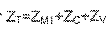
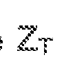
- the measuring device is, for example a voltmeter, and in particular a voltmeter integrated in an electronic card further comprising the comparator. It is thus possible to know the accumulated impedance Z of the user's body from the measurement of and monitoring current Is flowing in the electrical monitoring circuit.
- This impedance can be compared to a threshold impedance value which increases the impedance value of the human body, and preferably increases the Impedance value by a factor of 3 of the human body.
- the value that increases the impedance can be chosen equal to 20k ⁇ , and preferably greater than 100k ⁇ . It thus takes into account, in addition, a contact value between the finger of the user and the cutting member unlikely to generate a wound during actuation of the cutting member.
- the electrical monitoring characteristic can be a voltage that is a function of the monitoring voltage and the threshold electrical characteristic can be a threshold voltage that is a function of the impedance value.
- the electrical monitoring characteristic may be equal to the monitoring voltage and the threshold electrical characteristic can be equal to a voltage equal to the product of the impedance value increasing a conduction impedance value of the human body and the monitoring current.
- the electrical monitoring characteristic may be an impedance value depending on the monitoring voltage and the monitoring current
- the threshold characteristic may be an impedance value depending on the value. impedance increasing a conduction impedance value of the human body.
- the electrical monitoring characteristic can be equal to an impedance Z equal to the ratio of the monitoring voltage to the monitoring current
- the threshold characteristic may be equal to the impedance value increasing a value of Conduction impedance
- the comparison between. Z impedance and impedance or, as mentioned previously, the comparison of the monitoring voltage with a tension or, more generally, the comparison of another electrical monitoring characteristic, depending on the monitoring voltage, with an electrical threshold characteristic, a function of an impedance increasing the impedance of the human body, is performed by the comparator.
- the value the value or more generally the value of an electrical threshold function function of an impedance increasing the impedance of the human body can be stored in a memory connected to the comparator.
- the threshold values contained in the memory can be set at the tool's manufacture. Memory access can also be provided to modify the threshold values so as to modify, if necessary, the sensitivity of the triggering of the emergency stop device.
- the electrical generator comprises a current source
- it can be connected in parallel to the adjustment impedance, connected in series in the electrical monitoring circuit.
- the Ohm's law then makes it possible to determine the value Is of the current flowing in the monitoring circuit.
- the electric generator may be an AC generator or a DC generator.
- An AC generator has, for example, an operating frequency of 10 kHz.
- the use of an alternating monitoring current enables the device to operate when the conductive cutter is covered with a thin layer of electrical insulation, for example an anticorrosive layer or an antifouling layer.
- the blade of a pruner can be covered with a thin PTFE coating so as to facilitate its sliding on the counterblade during cutting while avoiding corrosion. Indeed, in this case, the contact between the finger of the user and the cutter may be a predominantly capacitive contact. It should be noted here, however, that the cutting edge of the blade is freed from this type of coating, the cutting edge of the blade being too tapered for such a protective coating to adhere thereto.
- the cutting tool may further comprise a device for monitoring an electrical potential of the cutting member.
- the electrical potential monitoring device is connected to the emergency stop device to cause an emergency stop when the electric potential of the cutter is out of a set range.
- the monitoring device makes it possible to avoid situations in which the establishment of the electrical monitoring characteristics would be affected by a modified potential of the cutting member, and in particular by a non-zero potential of the cutting member.
- the cutting member is preferably connected to a ground potential of the tool.
- a modification of the potential of the cutting member may result, for example, during an unexpected contact of the cutting member with a energized metal conductor, such as an electric fence, for example.
- the cutting tool may include a grounding impedance, a value exceeding by several orders of magnitude the impedance value increasing the impedance value of the human body, the grounding impedance connecting electrically the second manual contact electrode to the cutting member.
- the cutting tool can be configured to further cause one of an emergency stop and a shutdown, when the monitoring voltage measured by the measuring device is zero.
- the grounding impedance avoids a floating potential of the second manual contact electrode. Its value is very high, for example several million ohms, so as not to introduce significant current into the second manual contact electrode, and thus not to affect the measurement of the monitoring voltage.
- the grounding impedance it is possible, in the absence of hand contact simultaneously on the first and the second manual contact electrode, to have a monitoring voltage of zero at the level of the second electrode. Measuring a voltage zero then allows, as indicated above to trigger the emergency stop device, or a simple deactivation, to prohibit the use of the tool.
- the activation means of the emergency stop device being inoperative then to detect a risk of finger contact with the cutting member.
- the user may wear electrical conductive gloves if necessary, especially to protect themselves from the cold. It is important however that the touch of the hand with the glove does not generate significant impedance variations, and especially greater than the variations of a direct contact of the hand with the manual contact electrode.
- FIG. 1 is a simplified schematic representation of the main features and functions of a cutting tool according to the invention.
- Figure 2 is a simplified schematic representation of a pruner according to the invention. Identical or similar parts of Figures 1 and 2 bear the same numerical references so as to facilitate the transfer of a figure to another and so as to repeat the description.
- FIG. 1 diagrammatically shows a cutting tool 10 provided with a cutting member 12
- the cutting member 12 is electrically connected to the ground potential 18 of the tool.
- the cutting tool further comprises an electric motor 20 mechanically connected to the cutting member 12, by a transmission mechanism 22.
- the transmission mechanism transmits to the cutter the mechanical energy supplied by the engine. It allows to drive the cutting member according to a pivoting movement, a circular rotary movement or a translational movement, depending on the nature of the cutting member.
- the electric motor 20 is associated with a power supply 24 and an electronic control board 26 of the engine.
- the electronic control board 26 can receive signals from a cutting actuator 28 actuable by a hand of the user holding a gripping handle 30 of the cutting tool 10.
- the cutting release member 28, for example a trigger is disposed near the gripping handle 30, so as to be actuated by the hand that grips the handle.
- the gripping handle 30 is made of insulating plastic, and thus electrically insulated from the cutting member. It is further provided with a pair of manual contact electrodes 32 and 34 formed respectively on two substantially opposite portions of the handle.
- the manual contact electrodes are metal electrodes or conductive plastic electrodes, with which the user's hand necessarily comes into contact when the pruner is grasped by its handle. They are electrically insulated from one another and are electrically isolated from the cutting member 12.
- One of the first or the second electrode may also be disposed on the trigger of the cutting triggering member, operated by the hand grasping the handle.
- An emergency stop device 40 of the secateur electric motor 20 is governed by an electrical monitoring circuit 42.
- the electrical monitoring circuit 42 includes components of the cutting tool but may also include parts of the body of the cutting tool. a human using pruner 10.
- the electrical circuit 42 includes in particular in series, an adjustment impedance 52, the first electrode 32 of manual contact, the cutting member 12 and an electric generator 56 of a monitoring current.
- the electric generator is for example a voltage source, for example an electric battery, or a current source.
- the adjustment impedance may be formed of one or more electrical components whose value electrical impedance is known. It can be included in the electric generator 56. It is, for example, an electrical resistance with a value, for example, of 100k ⁇ . Its value is not critical, however. It can be, for example, between 1 ⁇ and 200 k ⁇ .
- a measure of tension at the terminals of the adjustment impedance then makes it possible to determine the monitoring current Is flowing in the monitoring circuit.
- the adjustment impedance is not necessary when the electric generator 56 comprises a current source generating directly, when closing the electrical monitoring circuit 42, a current of defined value.
- the electrical monitoring circuit 42 is normally an open circuit having, therefore, a quasi-infinite overall impedance and a zero current.
- the adjustment impedance 52 is in series. successively with the first manual contact electrode, a contact impedance 60 of the user's hand with the first manual contact electrode 32, an impedance 62 of the user's body, a contact impedance 64 of the finger cutting, and finally the cutting member 12.
- the impedance of the wiring and that of the cutter are neglected here. It also neglects the impedance of the electric generator 56 which is considered here as a voltage source.
- the generator 56 circulates in the circuit a monitoring current Is.
- the value of the current Is can be predefined by the current generator when it comprises a current source. It can also be determined from a voltage measurement made across the adjustment impedance 52 when the generator comprises a voltage source, for example.
- the voltage measurement ⁇ across the adjustment impedance 52, of value is performed by an integrated voltmeter 53.
- a voltage measuring device 44 for example another integrated voltmeter, is connected between the mass 18 of the cutting tool 10 and the second manual contact electrode. It measures a potential or more precisely a monitoring voltage between the mass 18 and the second manual contact electrode 34.
- the voltage delivered by the integrated voltmeter 53 is supplied to a digital management unit 74.
- the digital management unit for example a microcontroller, or a dedicated integrated circuit makes it possible to perform various operations.
- a first operation is to calculate the monitoring current Is by carrying out a report
- a second operation may consist in calculating an impedance value Z from the monitoring voltage and the monitoring current.
- the digital management unit 74 is a comparator.
- the electrical threshold characteristic is respectively crossed and the emergency stop is triggered.
- the comparisons may be made on other parameters as a function of the aforementioned parameters and also calculated by the digital management unit 74. It is possible to compare conductances rather than impedances, for example.
- the emergency stop device 40 is triggered.
- the electrical threshold characteristics used by the comparator of the digital management unit for example the values
- the emergency stop device comprises the electronic card 26 for controlling the electric motor.
- the electronic control board 26 receives the emergency stop signal indicated by a dotted line link.
- the motor control electronic card is configured to trigger a movement of the motor that is able to counter the movement of the cutting member and / or to cause electromagnetic braking of the motor and the cutter using the inductive circuits of the electric motor.
- a cut in the power supply can also be operated. It can be performed by a switch 27, and in particular a transistor switch, controlled by the digital management unit 74.
- the digital management unit 74 and in particular the comparator which it constitutes, as well as the electronic card 26 for controlling the actuating motor, can be produced in the form of a single integrated component .
- Reference 80 designates a grounding impedance. This is in the example of Figure 1 of an electrical resistance of more than 1 ⁇ connected between the second manual contact electrode 34 and ground 18 of the cutting tool. It avoids a floating voltage of the second manual contact electrode. It also makes it possible to set the voltage of the second manual contact electrode to zero when the second manual contact electrode is not in contact with the user's hand.
- the measurement of a zero monitoring voltage by the voltage measuring device 44 can thus be exploited by the digital management unit 74 to prohibit the operation of the tool or to cause an emergency stop.
- the power supply of the actuating motor 20 can simply be inhibited in the case of the measurement of a zero monitoring voltage. This allows, for example to prevent the operation of the tool when it is held by a user wearing insulating gloves that prevent the detection of contact with the cutting member. Virtually no current flows through the grounding impedance or part of the user's hand into contact with the second manual contact electrode. So the potential measured on the second manual contact electrode is almost identical to a potential which would be measured between a dummy point C inside the body of the user who grasps the handle 30 and the cutting member, and thus the mass of the tool.
- the reference 76 designates a control electrode electrically connected to the cutting member 12. It is designed to allow an emergency stop test without touching the cutting member. It is sufficient that the user, grasping the handle 30, simultaneously touches with his free hand the control electrode 76 to cause an emergency stop.
- the control electronic card 26 may optionally be configured to require such a periodic control operation, so as to ensure the proper operation of the emergency stop device.
- a monitoring circuit 78 of the potential of the cutting member is also provided. It is built around a voltmeter and is also connected to the electronic control board 26 of the electric motor 20 to cause an emergency stop when an electrical potential of the cutting member 12 becomes different from a set value. . In the exemplary embodiment illustrated, it is verified that the electric potential of the cutting member is at the ground potential of the tool.
- the voltmeter can be an integrated component forming part of the same electronic card as the digital management unit, FIG. 2 shows a pruner, with a partial section revealing the electric drive motor of the cutting member 12, as well as the transmission mechanism 22 between the motor 20 and a movable blade 14 of the cutting member 12 .
- the cutting member 12 comprises, in the case of pruner, a fixed blade 16, or hook, and a movable blade 14, driven by the electric motor 20, and closing on the fixed blade following a solicitation of the cutting trigger member 28 which is here a trigger.
- a trigger signal is directed to the engine control board 26 shown symbolically.
- Figure 2 illustrates the contact of the hand with the first and second manual contact electrodes 32 and 34 when the user grasps the grip 30 for functional use of the pruner. It may be noted that the fingers, and more specifically the middle finger, the ring finger and the little finger, come into contact with the first manual contact electrode 32 and therefore with the electric monitoring circuit.
- the first manual contact electrode 32 is here arranged on a lower part of the gripping handle 30, in a position of use of the pruner.
- the palm P of the hand comes into contact with the second manual contact electrode 34 disposed here on an upper part of the gripping handle 30.
- the index I of the hand is free to actuate the trigger 28.
- the free hand of the user is shown in a position where a finger comes into contact with the cutter.
- the hand holding the seizing grip gripper 10 and the hand coming into contact with the cutting member are connected by a line symbolizing the human body.
- the electronic control board 26 of the electric motor is connected to the electric motor so as to control the power supply of the different phases of the motor It can be used to control the rotation of the motor in one direction causing the closing of the movable blade 14 on the hook 16. It can also be used, during an emergency stop, in a reverse direction of rotation, causing the opening of the organ cut, and countering its closure. Finally, it can be used as an electromagnetic brake, for example by shorting the motor phases.
- the control electronic card is, moreover, connected to a power supply 24, such as an electric battery carried, for example, on the back of the user,
- Figure 2 also shows the monitoring voltage measured between the pruner mass and the second manual contact electrode 34.
- Reference 13 indicates a thin anticorrosive and / or electrical insulating coating, such as a layer of PTFE (polytetrafluoroethylene) capable of covering the blades 14, 16 of the secateurs.
- PTFE polytetrafluoroethylene
- the use of such a layer of insulation does not prevent the operation of the tool of the invention and in particular does not prevent the triggering of the emergency stop device when the electric generator 56 is a generator.
- alternating current can flow in the event of contact of the user's finger with the blades 14, 16 secateur, despite the electrical insulating layer. In this case the impedance finger contact with the cutting tool, has a capacitive component.
Landscapes
- Engineering & Computer Science (AREA)
- Life Sciences & Earth Sciences (AREA)
- Mechanical Engineering (AREA)
- Forests & Forestry (AREA)
- General Engineering & Computer Science (AREA)
- Biodiversity & Conservation Biology (AREA)
- Ecology (AREA)
- Environmental Sciences (AREA)
- Remote Sensing (AREA)
- Geology (AREA)
- Environmental & Geological Engineering (AREA)
- Physics & Mathematics (AREA)
- General Life Sciences & Earth Sciences (AREA)
- General Physics & Mathematics (AREA)
- Geophysics (AREA)
- Scissors And Nippers (AREA)
- Sawing (AREA)
- Auxiliary Devices For Machine Tools (AREA)
- Accessories And Tools For Shearing Machines (AREA)
- Details Of Cutting Devices (AREA)
Abstract
Description














Claims


Priority Applications (9)
| Application Number | Priority Date | Filing Date | Title |
|---|---|---|---|
| JP2020528343A JP7177834B2 (ja) | 2017-11-23 | 2018-11-20 | 自動緊急停止式電動切断工具 |
| CN201880075839.8A CN111372738B (zh) | 2017-11-23 | 2018-11-20 | 具有自动紧急停止的电动切割设备 |
| AU2018372368A AU2018372368A1 (en) | 2017-11-23 | 2018-11-20 | Electric cutting device with automatic emergency stop |
| KR1020207017669A KR102671772B1 (ko) | 2017-11-23 | 2018-11-20 | 자동 비상 정지 기능을 구비한 전기 절단 장치 |
| US16/646,833 US11384901B2 (en) | 2017-11-23 | 2018-11-20 | Electric cutting tool with automatic emergency stop |
| EP18825751.3A EP3713726B1 (fr) | 2017-11-23 | 2018-11-20 | Outil de coupe électrique à arrêt d'urgence automatique |
| ES18825751T ES2905159T3 (es) | 2017-11-23 | 2018-11-20 | Herramienta de corte eléctrica con parada de emergencia automática |
| MX2020005371A MX2020005371A (es) | 2017-11-23 | 2018-11-20 | Dispositivo de corte electrico con detencion de emergencia automatica. |
| BR112020008685-1A BR112020008685A2 (pt) | 2017-11-23 | 2018-11-20 | ferramenta de corte elétrica com parada de emergência automática |
Applications Claiming Priority (2)
| Application Number | Priority Date | Filing Date | Title |
|---|---|---|---|
| FR1771255A FR3073773B1 (fr) | 2017-11-23 | 2017-11-23 | Outil de coupe electrique a arret d'urgence automatique |
| FR17/71255 | 2017-11-23 |
Publications (1)
| Publication Number | Publication Date |
|---|---|
| WO2019102129A1 true WO2019102129A1 (fr) | 2019-05-31 |
Family
ID=61599450
Family Applications (1)
| Application Number | Title | Priority Date | Filing Date |
|---|---|---|---|
| PCT/FR2018/052914 Ceased WO2019102129A1 (fr) | 2017-11-23 | 2018-11-20 | Outil de coupe électrique à arrêt d'urgence automatique |
Country Status (11)
| Country | Link |
|---|---|
| US (1) | US11384901B2 (fr) |
| EP (1) | EP3713726B1 (fr) |
| JP (1) | JP7177834B2 (fr) |
| KR (1) | KR102671772B1 (fr) |
| CN (1) | CN111372738B (fr) |
| AU (1) | AU2018372368A1 (fr) |
| BR (1) | BR112020008685A2 (fr) |
| ES (1) | ES2905159T3 (fr) |
| FR (1) | FR3073773B1 (fr) |
| MX (1) | MX2020005371A (fr) |
| WO (1) | WO2019102129A1 (fr) |
Cited By (4)
| Publication number | Priority date | Publication date | Assignee | Title |
|---|---|---|---|---|
| EP3498083A1 (fr) | 2017-12-13 | 2019-06-19 | Innovation Fabrication Commercialisation Infaco | Sécateur motorisé électroportatif muni d'un dispositif de sécurité plus ergonomique et plus sûr |
| CN110547097A (zh) * | 2019-10-18 | 2019-12-10 | 郑州航空工业管理学院 | 一种一果一动的智能可控采摘剪 |
| WO2020089792A1 (fr) * | 2018-10-30 | 2020-05-07 | Redcap Technology S.R.L. | Système de protection et procédé de fonctionnement associé dans un outil de coupe portable |
| ES2909461A1 (es) * | 2020-11-05 | 2022-05-06 | Sanchez Jose Maria Martinez | Dispositivo de protección |
Families Citing this family (11)
| Publication number | Priority date | Publication date | Assignee | Title |
|---|---|---|---|---|
| US10172292B2 (en) * | 2016-10-17 | 2019-01-08 | Robert Bosch Gmbh | Cutting device |
| USD926007S1 (en) * | 2020-12-29 | 2021-07-27 | Yongkang Huiyan Industry and Trade Co., Ltd. | Chainsaw |
| US20240300063A1 (en) * | 2021-02-18 | 2024-09-12 | Sawstop Holding Llc | Detection systems for aim-enabled power tools |
| KR102743722B1 (ko) * | 2021-06-17 | 2024-12-17 | 주식회사 아임삭 | 퀵 클로즈 기능을 갖는 전동식 전지가위 |
| CN118434523A (zh) | 2021-10-22 | 2024-08-02 | 环救援有限公司 | 用于安全地横切被困在附肢上的环状物的环状物切割器 |
| USD1003137S1 (en) * | 2022-03-25 | 2023-10-31 | Innovation Fabrication Commercialisation Infaco | Hedge trimmer |
| US12504735B1 (en) * | 2022-11-16 | 2025-12-23 | Daniel J. Marcej | Z-axis setting tool |
| USD1089340S1 (en) | 2023-06-22 | 2025-08-19 | Ring Rescue Inc. | Ring cutter |
| US12343893B2 (en) * | 2023-08-25 | 2025-07-01 | Altec Industries, Inc. | Remotely operated cutting device |
| FR3161340A1 (fr) * | 2024-04-23 | 2025-10-24 | Felco Sa | Outil électroportatif et son procédé de fabrication |
| EP4640378A1 (fr) * | 2024-04-23 | 2025-10-29 | Felco SA | Outil électroportatif et son procédé de fabrication |
Citations (13)
| Publication number | Priority date | Publication date | Assignee | Title |
|---|---|---|---|---|
| US5025175A (en) | 1989-10-10 | 1991-06-18 | Townsend Engineering Company | Safety means for powered machinery |
| FR2712837A1 (fr) | 1993-11-22 | 1995-06-02 | Delmas Daniel | Dispositif de protection et de sécurité pour utilisateur d'outils coupants. |
| FR2779669A1 (fr) | 1998-06-16 | 1999-12-17 | Electronique Angelidis Et Sarr | Dispositif de securite pour la conduite d'une machine-outil |
| FR2831476A1 (fr) | 2001-10-26 | 2003-05-02 | Jean Pierre Loubes | Dispositif de securite pour outil de coupe manuel motorise |
| FR2838998A1 (fr) | 2002-04-26 | 2003-10-31 | Infaco Sa | Dispositif de securite pour outils coupants ou tranchants motorises, secateur securise et circuit de protection pour de tels outils |
| FR2846729A1 (fr) | 2002-11-04 | 2004-05-07 | Manulatex France | Dispositif de protection et de securite programmable pour outils motorises |
| US7365955B2 (en) | 1998-12-02 | 2008-04-29 | Corey Alexander Mather | Material processing machine |
| FR2963081A1 (fr) | 2010-07-24 | 2012-01-27 | Infaco | Dispositif de securite pour outils de coupe electroportatifs |
| WO2012025458A1 (fr) | 2010-08-24 | 2012-03-01 | Redcap Technology S.R.L. | Appareil de freinage à actionnement commandé pour outils de coupe portatifs, et outil de coupe pour cet appareil |
| WO2012025456A1 (fr) * | 2010-08-24 | 2012-03-01 | Redcap Technology S.R.L. | Système de sécurité dans un outil portable |
| EP2490865A1 (fr) | 2009-10-23 | 2012-08-29 | Robert Bosch GmbH | Logique de détecteurs de protection pour machine-outil électrique portative |
| FR3001404A1 (fr) | 2013-01-30 | 2014-08-01 | Midi Ingenierie | Outil de coupe securise |
| EP2825811A1 (fr) | 2012-03-15 | 2015-01-21 | Flash Elettronica di Duccio Gemignani | Outil électrique de découpe avec butée de sûreté |
Family Cites Families (21)
| Publication number | Priority date | Publication date | Assignee | Title |
|---|---|---|---|---|
| JPS59184778U (ja) * | 1983-05-25 | 1984-12-08 | フイリツプス工業振興株式会社 | 自動動作電気ひげそり器 |
| US5160289A (en) * | 1989-10-10 | 1992-11-03 | Townsend Engineering Company | Safety means for powered machinery |
| JPH07108478B2 (ja) * | 1990-12-20 | 1995-11-22 | 祥一郎 垣中 | 安全装置 |
| JP3537649B2 (ja) * | 1997-10-30 | 2004-06-14 | 株式会社マキタ | 電動式せん定はさみ |
| US7210383B2 (en) * | 2000-08-14 | 2007-05-01 | Sd3, Llc | Detection system for power equipment |
| US7377199B2 (en) * | 2000-09-29 | 2008-05-27 | Sd3, Llc | Contact detection system for power equipment |
| US7284467B2 (en) | 2000-08-14 | 2007-10-23 | Sd3, Llc | Apparatus and method for detecting dangerous conditions in power equipment |
| US6857345B2 (en) * | 2000-08-14 | 2005-02-22 | Sd3, Llc | Brake positioning system |
| DE60238424D1 (de) * | 2001-07-11 | 2011-01-05 | Black & Decker Inc | Sicherheitsmechanismen für ein strombetriebenes werkzeug |
| JP4003453B2 (ja) * | 2001-12-26 | 2007-11-07 | アイシン精機株式会社 | 人体検出装置 |
| CA2448479C (fr) * | 2002-11-12 | 2009-05-05 | Makita Corporation | Outils mecaniques |
| JP4255679B2 (ja) | 2002-11-12 | 2009-04-15 | 株式会社マキタ | 電動工具 |
| US7556238B2 (en) * | 2005-07-20 | 2009-07-07 | Fisher Controls International Llc | Emergency shutdown system |
| KR101166700B1 (ko) * | 2008-09-16 | 2012-07-27 | 대한민국 | 전동식 전지 가위 |
| CN101639672B (zh) * | 2009-05-11 | 2011-06-29 | 东莞市飞新达精密机械科技有限公司 | 一种模切机控制方法 |
| CN202045667U (zh) * | 2011-03-25 | 2011-11-23 | 上海汇盛无线电专用科技有限公司 | 一种可实现主轴急停的切片机电路 |
| PT11844Y (pt) * | 2014-09-18 | 2020-03-30 | Scott Automation & Robotics Pty Ltd | Dispositivo de segurança para proteger um operador de uma serra electricamente motorizada. |
| FR3029036B1 (fr) * | 2014-11-25 | 2016-11-25 | Pellenc Sa | Procede et dispositif de commande pour equipement a moteur. |
| DE102016207706A1 (de) * | 2016-05-04 | 2017-11-09 | Robert Bosch Gmbh | Handwerkzeugmaschine und Verfahren mit einer Handwerkzeugmaschine |
| ES1184658Y (es) * | 2017-05-19 | 2017-09-08 | Gallaguet Carbones Rauel | Tijera de podar electrica con dispositivo de seguridad |
| CN107053019A (zh) * | 2017-05-20 | 2017-08-18 | 奥拓福水刀有限公司 | 一种冷切割消防用手持切割枪 |
-
2017
- 2017-11-23 FR FR1771255A patent/FR3073773B1/fr not_active Expired - Fee Related
-
2018
- 2018-11-20 EP EP18825751.3A patent/EP3713726B1/fr active Active
- 2018-11-20 KR KR1020207017669A patent/KR102671772B1/ko active Active
- 2018-11-20 CN CN201880075839.8A patent/CN111372738B/zh active Active
- 2018-11-20 MX MX2020005371A patent/MX2020005371A/es unknown
- 2018-11-20 US US16/646,833 patent/US11384901B2/en active Active
- 2018-11-20 WO PCT/FR2018/052914 patent/WO2019102129A1/fr not_active Ceased
- 2018-11-20 BR BR112020008685-1A patent/BR112020008685A2/pt not_active Application Discontinuation
- 2018-11-20 ES ES18825751T patent/ES2905159T3/es active Active
- 2018-11-20 AU AU2018372368A patent/AU2018372368A1/en not_active Abandoned
- 2018-11-20 JP JP2020528343A patent/JP7177834B2/ja active Active
Patent Citations (14)
| Publication number | Priority date | Publication date | Assignee | Title |
|---|---|---|---|---|
| US5025175A (en) | 1989-10-10 | 1991-06-18 | Townsend Engineering Company | Safety means for powered machinery |
| FR2712837A1 (fr) | 1993-11-22 | 1995-06-02 | Delmas Daniel | Dispositif de protection et de sécurité pour utilisateur d'outils coupants. |
| FR2779669A1 (fr) | 1998-06-16 | 1999-12-17 | Electronique Angelidis Et Sarr | Dispositif de securite pour la conduite d'une machine-outil |
| US7365955B2 (en) | 1998-12-02 | 2008-04-29 | Corey Alexander Mather | Material processing machine |
| FR2831476A1 (fr) | 2001-10-26 | 2003-05-02 | Jean Pierre Loubes | Dispositif de securite pour outil de coupe manuel motorise |
| FR2838998A1 (fr) | 2002-04-26 | 2003-10-31 | Infaco Sa | Dispositif de securite pour outils coupants ou tranchants motorises, secateur securise et circuit de protection pour de tels outils |
| FR2846729A1 (fr) | 2002-11-04 | 2004-05-07 | Manulatex France | Dispositif de protection et de securite programmable pour outils motorises |
| EP2490865A1 (fr) | 2009-10-23 | 2012-08-29 | Robert Bosch GmbH | Logique de détecteurs de protection pour machine-outil électrique portative |
| FR2963081A1 (fr) | 2010-07-24 | 2012-01-27 | Infaco | Dispositif de securite pour outils de coupe electroportatifs |
| WO2012025458A1 (fr) | 2010-08-24 | 2012-03-01 | Redcap Technology S.R.L. | Appareil de freinage à actionnement commandé pour outils de coupe portatifs, et outil de coupe pour cet appareil |
| WO2012025456A1 (fr) * | 2010-08-24 | 2012-03-01 | Redcap Technology S.R.L. | Système de sécurité dans un outil portable |
| EP2825811A1 (fr) | 2012-03-15 | 2015-01-21 | Flash Elettronica di Duccio Gemignani | Outil électrique de découpe avec butée de sûreté |
| EP2825811B1 (fr) * | 2012-03-15 | 2016-02-24 | Flash Elettronica di Duccio Gemignani | Outil électrique de découpe avec butée de sûreté |
| FR3001404A1 (fr) | 2013-01-30 | 2014-08-01 | Midi Ingenierie | Outil de coupe securise |
Cited By (6)
| Publication number | Priority date | Publication date | Assignee | Title |
|---|---|---|---|---|
| EP3498083A1 (fr) | 2017-12-13 | 2019-06-19 | Innovation Fabrication Commercialisation Infaco | Sécateur motorisé électroportatif muni d'un dispositif de sécurité plus ergonomique et plus sûr |
| EP3498083B1 (fr) * | 2017-12-13 | 2021-09-15 | Innovation Fabrication Commercialisation Infaco | Sécateur motorisé électroportatif muni d'un dispositif de sécurité plus ergonomique et plus sûr |
| WO2020089792A1 (fr) * | 2018-10-30 | 2020-05-07 | Redcap Technology S.R.L. | Système de protection et procédé de fonctionnement associé dans un outil de coupe portable |
| US12296500B2 (en) | 2018-10-30 | 2025-05-13 | Redcap Technology S.R.L. | Active protection system and relative operating method in a portable cutting tool |
| CN110547097A (zh) * | 2019-10-18 | 2019-12-10 | 郑州航空工业管理学院 | 一种一果一动的智能可控采摘剪 |
| ES2909461A1 (es) * | 2020-11-05 | 2022-05-06 | Sanchez Jose Maria Martinez | Dispositivo de protección |
Also Published As
| Publication number | Publication date |
|---|---|
| FR3073773A1 (fr) | 2019-05-24 |
| US11384901B2 (en) | 2022-07-12 |
| MX2020005371A (es) | 2020-08-06 |
| BR112020008685A2 (pt) | 2020-10-27 |
| KR102671772B1 (ko) | 2024-06-04 |
| JP2021504016A (ja) | 2021-02-15 |
| CN111372738B (zh) | 2022-01-21 |
| CN111372738A (zh) | 2020-07-03 |
| EP3713726A1 (fr) | 2020-09-30 |
| EP3713726B1 (fr) | 2021-10-27 |
| JP7177834B2 (ja) | 2022-11-24 |
| FR3073773B1 (fr) | 2019-10-25 |
| ES2905159T3 (es) | 2022-04-07 |
| AU2018372368A1 (en) | 2020-05-07 |
| US20200347991A1 (en) | 2020-11-05 |
| KR20200088436A (ko) | 2020-07-22 |
Similar Documents
| Publication | Publication Date | Title |
|---|---|---|
| EP3713726B1 (fr) | Outil de coupe électrique à arrêt d'urgence automatique | |
| EP3714199B1 (fr) | Outil de coupe électrique à arrêt d'urgence automatique | |
| EP3714198B1 (fr) | Dispositif de commande, pour outil motorisé et outil sécurisé comprenant un tel dispositif de commande | |
| WO2016083694A1 (fr) | Procédé et dispositif de commande pour équipement à moteur | |
| EP3498083B1 (fr) | Sécateur motorisé électroportatif muni d'un dispositif de sécurité plus ergonomique et plus sûr | |
| EP2951483B1 (fr) | Outil de coupe sécurise et methode pour securiser l'utilisation d'un outil | |
| FR3074403A1 (fr) | Dispositif de securite, base sur l’impedance, pour secateur motorise electroportatif. | |
| EP3921660B1 (fr) | Dispositif de vérification d'absence de tension d'un circuit électrique | |
| EP3379669B1 (fr) | Appareil de coupure de courant électrique comportant un afficheur à cristaux liquides et un mécanisme presseur | |
| FR2917940A1 (fr) | Electrificateur de cloture electrique |
Legal Events
| Date | Code | Title | Description |
|---|---|---|---|
| 121 | Ep: the epo has been informed by wipo that ep was designated in this application |
Ref document number: 18825751 Country of ref document: EP Kind code of ref document: A1 |
|
| ENP | Entry into the national phase |
Ref document number: 2018372368 Country of ref document: AU Date of ref document: 20181120 Kind code of ref document: A |
|
| ENP | Entry into the national phase |
Ref document number: 2020528343 Country of ref document: JP Kind code of ref document: A |
|
| NENP | Non-entry into the national phase |
Ref country code: DE |
|
| ENP | Entry into the national phase |
Ref document number: 20207017669 Country of ref document: KR Kind code of ref document: A |
|
| ENP | Entry into the national phase |
Ref document number: 2018825751 Country of ref document: EP Effective date: 20200623 |
|
| REG | Reference to national code |
Ref country code: BR Ref legal event code: B01A Ref document number: 112020008685 Country of ref document: BR |
|
| ENP | Entry into the national phase |
Ref document number: 112020008685 Country of ref document: BR Kind code of ref document: A2 Effective date: 20200430 |