WO2019106976A1 - 方向性電磁鋼板およびその製造方法 - Google Patents
方向性電磁鋼板およびその製造方法 Download PDFInfo
- Publication number
- WO2019106976A1 WO2019106976A1 PCT/JP2018/038133 JP2018038133W WO2019106976A1 WO 2019106976 A1 WO2019106976 A1 WO 2019106976A1 JP 2018038133 W JP2018038133 W JP 2018038133W WO 2019106976 A1 WO2019106976 A1 WO 2019106976A1
- Authority
- WO
- WIPO (PCT)
- Prior art keywords
- film
- steel sheet
- coating
- alkali metal
- electrical steel
- Prior art date
- Legal status (The legal status is an assumption and is not a legal conclusion. Google has not performed a legal analysis and makes no representation as to the accuracy of the status listed.)
- Ceased
Links
Images
Classifications
-
- C—CHEMISTRY; METALLURGY
- C23—COATING METALLIC MATERIAL; COATING MATERIAL WITH METALLIC MATERIAL; CHEMICAL SURFACE TREATMENT; DIFFUSION TREATMENT OF METALLIC MATERIAL; COATING BY VACUUM EVAPORATION, BY SPUTTERING, BY ION IMPLANTATION OR BY CHEMICAL VAPOUR DEPOSITION, IN GENERAL; INHIBITING CORROSION OF METALLIC MATERIAL OR INCRUSTATION IN GENERAL
- C23C—COATING METALLIC MATERIAL; COATING MATERIAL WITH METALLIC MATERIAL; SURFACE TREATMENT OF METALLIC MATERIAL BY DIFFUSION INTO THE SURFACE, BY CHEMICAL CONVERSION OR SUBSTITUTION; COATING BY VACUUM EVAPORATION, BY SPUTTERING, BY ION IMPLANTATION OR BY CHEMICAL VAPOUR DEPOSITION, IN GENERAL
- C23C28/00—Coating for obtaining at least two superposed coatings either by methods not provided for in a single one of groups C23C2/00 - C23C26/00 or by combinations of methods provided for in subclasses C23C and C25C or C25D
- C23C28/04—Coating for obtaining at least two superposed coatings either by methods not provided for in a single one of groups C23C2/00 - C23C26/00 or by combinations of methods provided for in subclasses C23C and C25C or C25D only coatings of inorganic non-metallic material
- C23C28/042—Coating for obtaining at least two superposed coatings either by methods not provided for in a single one of groups C23C2/00 - C23C26/00 or by combinations of methods provided for in subclasses C23C and C25C or C25D only coatings of inorganic non-metallic material including a refractory ceramic layer, e.g. refractory metal oxides, ZrO2, rare earth oxides
-
- B—PERFORMING OPERATIONS; TRANSPORTING
- B32—LAYERED PRODUCTS
- B32B—LAYERED PRODUCTS, i.e. PRODUCTS BUILT-UP OF STRATA OF FLAT OR NON-FLAT, e.g. CELLULAR OR HONEYCOMB, FORM
- B32B15/00—Layered products comprising a layer of metal
- B32B15/04—Layered products comprising a layer of metal comprising metal as the main or only constituent of a layer, which is next to another layer of the same or of a different material
-
- C—CHEMISTRY; METALLURGY
- C21—METALLURGY OF IRON
- C21D—MODIFYING THE PHYSICAL STRUCTURE OF FERROUS METALS; GENERAL DEVICES FOR HEAT TREATMENT OF FERROUS OR NON-FERROUS METALS OR ALLOYS; MAKING METAL MALLEABLE, e.g. BY DECARBURISATION OR TEMPERING
- C21D8/00—Modifying the physical properties of ferrous metals or ferrous alloys by deformation combined with, or followed by, heat treatment
- C21D8/02—Modifying the physical properties of ferrous metals or ferrous alloys by deformation combined with, or followed by, heat treatment during manufacturing of plates or strips
- C21D8/0221—Modifying the physical properties of ferrous metals or ferrous alloys by deformation combined with, or followed by, heat treatment during manufacturing of plates or strips characterised by the working steps
- C21D8/0226—Hot rolling
-
- C—CHEMISTRY; METALLURGY
- C21—METALLURGY OF IRON
- C21D—MODIFYING THE PHYSICAL STRUCTURE OF FERROUS METALS; GENERAL DEVICES FOR HEAT TREATMENT OF FERROUS OR NON-FERROUS METALS OR ALLOYS; MAKING METAL MALLEABLE, e.g. BY DECARBURISATION OR TEMPERING
- C21D8/00—Modifying the physical properties of ferrous metals or ferrous alloys by deformation combined with, or followed by, heat treatment
- C21D8/02—Modifying the physical properties of ferrous metals or ferrous alloys by deformation combined with, or followed by, heat treatment during manufacturing of plates or strips
- C21D8/0221—Modifying the physical properties of ferrous metals or ferrous alloys by deformation combined with, or followed by, heat treatment during manufacturing of plates or strips characterised by the working steps
- C21D8/0236—Cold rolling
-
- C—CHEMISTRY; METALLURGY
- C21—METALLURGY OF IRON
- C21D—MODIFYING THE PHYSICAL STRUCTURE OF FERROUS METALS; GENERAL DEVICES FOR HEAT TREATMENT OF FERROUS OR NON-FERROUS METALS OR ALLOYS; MAKING METAL MALLEABLE, e.g. BY DECARBURISATION OR TEMPERING
- C21D8/00—Modifying the physical properties of ferrous metals or ferrous alloys by deformation combined with, or followed by, heat treatment
- C21D8/12—Modifying the physical properties of ferrous metals or ferrous alloys by deformation combined with, or followed by, heat treatment during manufacturing of articles with special electromagnetic properties
- C21D8/1277—Modifying the physical properties of ferrous metals or ferrous alloys by deformation combined with, or followed by, heat treatment during manufacturing of articles with special electromagnetic properties involving a particular surface treatment
-
- C—CHEMISTRY; METALLURGY
- C21—METALLURGY OF IRON
- C21D—MODIFYING THE PHYSICAL STRUCTURE OF FERROUS METALS; GENERAL DEVICES FOR HEAT TREATMENT OF FERROUS OR NON-FERROUS METALS OR ALLOYS; MAKING METAL MALLEABLE, e.g. BY DECARBURISATION OR TEMPERING
- C21D9/00—Heat treatment, e.g. annealing, hardening, quenching or tempering, adapted for particular articles; Furnaces therefor
- C21D9/46—Heat treatment, e.g. annealing, hardening, quenching or tempering, adapted for particular articles; Furnaces therefor for sheet metals
-
- C—CHEMISTRY; METALLURGY
- C22—METALLURGY; FERROUS OR NON-FERROUS ALLOYS; TREATMENT OF ALLOYS OR NON-FERROUS METALS
- C22C—ALLOYS
- C22C38/00—Ferrous alloys, e.g. steel alloys
-
- C—CHEMISTRY; METALLURGY
- C22—METALLURGY; FERROUS OR NON-FERROUS ALLOYS; TREATMENT OF ALLOYS OR NON-FERROUS METALS
- C22C—ALLOYS
- C22C38/00—Ferrous alloys, e.g. steel alloys
- C22C38/02—Ferrous alloys, e.g. steel alloys containing silicon
-
- C—CHEMISTRY; METALLURGY
- C22—METALLURGY; FERROUS OR NON-FERROUS ALLOYS; TREATMENT OF ALLOYS OR NON-FERROUS METALS
- C22C—ALLOYS
- C22C38/00—Ferrous alloys, e.g. steel alloys
- C22C38/04—Ferrous alloys, e.g. steel alloys containing manganese
-
- C—CHEMISTRY; METALLURGY
- C22—METALLURGY; FERROUS OR NON-FERROUS ALLOYS; TREATMENT OF ALLOYS OR NON-FERROUS METALS
- C22C—ALLOYS
- C22C38/00—Ferrous alloys, e.g. steel alloys
- C22C38/06—Ferrous alloys, e.g. steel alloys containing aluminium
-
- C—CHEMISTRY; METALLURGY
- C22—METALLURGY; FERROUS OR NON-FERROUS ALLOYS; TREATMENT OF ALLOYS OR NON-FERROUS METALS
- C22C—ALLOYS
- C22C38/00—Ferrous alloys, e.g. steel alloys
- C22C38/60—Ferrous alloys, e.g. steel alloys containing lead, selenium, tellurium, or antimony, or more than 0.04% by weight of sulfur
-
- C—CHEMISTRY; METALLURGY
- C23—COATING METALLIC MATERIAL; COATING MATERIAL WITH METALLIC MATERIAL; CHEMICAL SURFACE TREATMENT; DIFFUSION TREATMENT OF METALLIC MATERIAL; COATING BY VACUUM EVAPORATION, BY SPUTTERING, BY ION IMPLANTATION OR BY CHEMICAL VAPOUR DEPOSITION, IN GENERAL; INHIBITING CORROSION OF METALLIC MATERIAL OR INCRUSTATION IN GENERAL
- C23C—COATING METALLIC MATERIAL; COATING MATERIAL WITH METALLIC MATERIAL; SURFACE TREATMENT OF METALLIC MATERIAL BY DIFFUSION INTO THE SURFACE, BY CHEMICAL CONVERSION OR SUBSTITUTION; COATING BY VACUUM EVAPORATION, BY SPUTTERING, BY ION IMPLANTATION OR BY CHEMICAL VAPOUR DEPOSITION, IN GENERAL
- C23C14/00—Coating by vacuum evaporation, by sputtering or by ion implantation of the coating forming material
- C23C14/06—Coating by vacuum evaporation, by sputtering or by ion implantation of the coating forming material characterised by the coating material
- C23C14/0641—Nitrides
-
- C—CHEMISTRY; METALLURGY
- C23—COATING METALLIC MATERIAL; COATING MATERIAL WITH METALLIC MATERIAL; CHEMICAL SURFACE TREATMENT; DIFFUSION TREATMENT OF METALLIC MATERIAL; COATING BY VACUUM EVAPORATION, BY SPUTTERING, BY ION IMPLANTATION OR BY CHEMICAL VAPOUR DEPOSITION, IN GENERAL; INHIBITING CORROSION OF METALLIC MATERIAL OR INCRUSTATION IN GENERAL
- C23C—COATING METALLIC MATERIAL; COATING MATERIAL WITH METALLIC MATERIAL; SURFACE TREATMENT OF METALLIC MATERIAL BY DIFFUSION INTO THE SURFACE, BY CHEMICAL CONVERSION OR SUBSTITUTION; COATING BY VACUUM EVAPORATION, BY SPUTTERING, BY ION IMPLANTATION OR BY CHEMICAL VAPOUR DEPOSITION, IN GENERAL
- C23C14/00—Coating by vacuum evaporation, by sputtering or by ion implantation of the coating forming material
- C23C14/06—Coating by vacuum evaporation, by sputtering or by ion implantation of the coating forming material characterised by the coating material
- C23C14/08—Oxides
-
- C—CHEMISTRY; METALLURGY
- C23—COATING METALLIC MATERIAL; COATING MATERIAL WITH METALLIC MATERIAL; CHEMICAL SURFACE TREATMENT; DIFFUSION TREATMENT OF METALLIC MATERIAL; COATING BY VACUUM EVAPORATION, BY SPUTTERING, BY ION IMPLANTATION OR BY CHEMICAL VAPOUR DEPOSITION, IN GENERAL; INHIBITING CORROSION OF METALLIC MATERIAL OR INCRUSTATION IN GENERAL
- C23C—COATING METALLIC MATERIAL; COATING MATERIAL WITH METALLIC MATERIAL; SURFACE TREATMENT OF METALLIC MATERIAL BY DIFFUSION INTO THE SURFACE, BY CHEMICAL CONVERSION OR SUBSTITUTION; COATING BY VACUUM EVAPORATION, BY SPUTTERING, BY ION IMPLANTATION OR BY CHEMICAL VAPOUR DEPOSITION, IN GENERAL
- C23C14/00—Coating by vacuum evaporation, by sputtering or by ion implantation of the coating forming material
- C23C14/06—Coating by vacuum evaporation, by sputtering or by ion implantation of the coating forming material characterised by the coating material
- C23C14/10—Glass or silica
-
- C—CHEMISTRY; METALLURGY
- C23—COATING METALLIC MATERIAL; COATING MATERIAL WITH METALLIC MATERIAL; CHEMICAL SURFACE TREATMENT; DIFFUSION TREATMENT OF METALLIC MATERIAL; COATING BY VACUUM EVAPORATION, BY SPUTTERING, BY ION IMPLANTATION OR BY CHEMICAL VAPOUR DEPOSITION, IN GENERAL; INHIBITING CORROSION OF METALLIC MATERIAL OR INCRUSTATION IN GENERAL
- C23C—COATING METALLIC MATERIAL; COATING MATERIAL WITH METALLIC MATERIAL; SURFACE TREATMENT OF METALLIC MATERIAL BY DIFFUSION INTO THE SURFACE, BY CHEMICAL CONVERSION OR SUBSTITUTION; COATING BY VACUUM EVAPORATION, BY SPUTTERING, BY ION IMPLANTATION OR BY CHEMICAL VAPOUR DEPOSITION, IN GENERAL
- C23C14/00—Coating by vacuum evaporation, by sputtering or by ion implantation of the coating forming material
- C23C14/06—Coating by vacuum evaporation, by sputtering or by ion implantation of the coating forming material characterised by the coating material
- C23C14/14—Metallic material, boron or silicon
- C23C14/16—Metallic material, boron or silicon on metallic substrates or on substrates of boron or silicon
-
- C—CHEMISTRY; METALLURGY
- C23—COATING METALLIC MATERIAL; COATING MATERIAL WITH METALLIC MATERIAL; CHEMICAL SURFACE TREATMENT; DIFFUSION TREATMENT OF METALLIC MATERIAL; COATING BY VACUUM EVAPORATION, BY SPUTTERING, BY ION IMPLANTATION OR BY CHEMICAL VAPOUR DEPOSITION, IN GENERAL; INHIBITING CORROSION OF METALLIC MATERIAL OR INCRUSTATION IN GENERAL
- C23C—COATING METALLIC MATERIAL; COATING MATERIAL WITH METALLIC MATERIAL; SURFACE TREATMENT OF METALLIC MATERIAL BY DIFFUSION INTO THE SURFACE, BY CHEMICAL CONVERSION OR SUBSTITUTION; COATING BY VACUUM EVAPORATION, BY SPUTTERING, BY ION IMPLANTATION OR BY CHEMICAL VAPOUR DEPOSITION, IN GENERAL
- C23C14/00—Coating by vacuum evaporation, by sputtering or by ion implantation of the coating forming material
- C23C14/22—Coating by vacuum evaporation, by sputtering or by ion implantation of the coating forming material characterised by the process of coating
- C23C14/34—Sputtering
-
- C—CHEMISTRY; METALLURGY
- C23—COATING METALLIC MATERIAL; COATING MATERIAL WITH METALLIC MATERIAL; CHEMICAL SURFACE TREATMENT; DIFFUSION TREATMENT OF METALLIC MATERIAL; COATING BY VACUUM EVAPORATION, BY SPUTTERING, BY ION IMPLANTATION OR BY CHEMICAL VAPOUR DEPOSITION, IN GENERAL; INHIBITING CORROSION OF METALLIC MATERIAL OR INCRUSTATION IN GENERAL
- C23C—COATING METALLIC MATERIAL; COATING MATERIAL WITH METALLIC MATERIAL; SURFACE TREATMENT OF METALLIC MATERIAL BY DIFFUSION INTO THE SURFACE, BY CHEMICAL CONVERSION OR SUBSTITUTION; COATING BY VACUUM EVAPORATION, BY SPUTTERING, BY ION IMPLANTATION OR BY CHEMICAL VAPOUR DEPOSITION, IN GENERAL
- C23C16/00—Chemical coating by decomposition of gaseous compounds, without leaving reaction products of surface material in the coating, i.e. chemical vapour deposition [CVD] processes
- C23C16/22—Chemical coating by decomposition of gaseous compounds, without leaving reaction products of surface material in the coating, i.e. chemical vapour deposition [CVD] processes characterised by the deposition of inorganic material, other than metallic material
- C23C16/30—Deposition of compounds, mixtures or solid solutions, e.g. borides, carbides, nitrides
- C23C16/301—AIII BV compounds, where A is Al, Ga, In or Tl and B is N, P, As, Sb or Bi
- C23C16/303—Nitrides
-
- C—CHEMISTRY; METALLURGY
- C23—COATING METALLIC MATERIAL; COATING MATERIAL WITH METALLIC MATERIAL; CHEMICAL SURFACE TREATMENT; DIFFUSION TREATMENT OF METALLIC MATERIAL; COATING BY VACUUM EVAPORATION, BY SPUTTERING, BY ION IMPLANTATION OR BY CHEMICAL VAPOUR DEPOSITION, IN GENERAL; INHIBITING CORROSION OF METALLIC MATERIAL OR INCRUSTATION IN GENERAL
- C23C—COATING METALLIC MATERIAL; COATING MATERIAL WITH METALLIC MATERIAL; SURFACE TREATMENT OF METALLIC MATERIAL BY DIFFUSION INTO THE SURFACE, BY CHEMICAL CONVERSION OR SUBSTITUTION; COATING BY VACUUM EVAPORATION, BY SPUTTERING, BY ION IMPLANTATION OR BY CHEMICAL VAPOUR DEPOSITION, IN GENERAL
- C23C16/00—Chemical coating by decomposition of gaseous compounds, without leaving reaction products of surface material in the coating, i.e. chemical vapour deposition [CVD] processes
- C23C16/22—Chemical coating by decomposition of gaseous compounds, without leaving reaction products of surface material in the coating, i.e. chemical vapour deposition [CVD] processes characterised by the deposition of inorganic material, other than metallic material
- C23C16/30—Deposition of compounds, mixtures or solid solutions, e.g. borides, carbides, nitrides
- C23C16/40—Oxides
-
- C—CHEMISTRY; METALLURGY
- C23—COATING METALLIC MATERIAL; COATING MATERIAL WITH METALLIC MATERIAL; CHEMICAL SURFACE TREATMENT; DIFFUSION TREATMENT OF METALLIC MATERIAL; COATING BY VACUUM EVAPORATION, BY SPUTTERING, BY ION IMPLANTATION OR BY CHEMICAL VAPOUR DEPOSITION, IN GENERAL; INHIBITING CORROSION OF METALLIC MATERIAL OR INCRUSTATION IN GENERAL
- C23C—COATING METALLIC MATERIAL; COATING MATERIAL WITH METALLIC MATERIAL; SURFACE TREATMENT OF METALLIC MATERIAL BY DIFFUSION INTO THE SURFACE, BY CHEMICAL CONVERSION OR SUBSTITUTION; COATING BY VACUUM EVAPORATION, BY SPUTTERING, BY ION IMPLANTATION OR BY CHEMICAL VAPOUR DEPOSITION, IN GENERAL
- C23C22/00—Chemical surface treatment of metallic material by reaction of the surface with a reactive liquid, leaving reaction products of surface material in the coating, e.g. conversion coatings, passivation of metals
- C23C22/05—Chemical surface treatment of metallic material by reaction of the surface with a reactive liquid, leaving reaction products of surface material in the coating, e.g. conversion coatings, passivation of metals using aqueous solutions
- C23C22/06—Chemical surface treatment of metallic material by reaction of the surface with a reactive liquid, leaving reaction products of surface material in the coating, e.g. conversion coatings, passivation of metals using aqueous solutions using aqueous acidic solutions with pH less than 6
- C23C22/07—Chemical surface treatment of metallic material by reaction of the surface with a reactive liquid, leaving reaction products of surface material in the coating, e.g. conversion coatings, passivation of metals using aqueous solutions using aqueous acidic solutions with pH less than 6 containing phosphates
- C23C22/08—Orthophosphates
-
- C—CHEMISTRY; METALLURGY
- C23—COATING METALLIC MATERIAL; COATING MATERIAL WITH METALLIC MATERIAL; CHEMICAL SURFACE TREATMENT; DIFFUSION TREATMENT OF METALLIC MATERIAL; COATING BY VACUUM EVAPORATION, BY SPUTTERING, BY ION IMPLANTATION OR BY CHEMICAL VAPOUR DEPOSITION, IN GENERAL; INHIBITING CORROSION OF METALLIC MATERIAL OR INCRUSTATION IN GENERAL
- C23C—COATING METALLIC MATERIAL; COATING MATERIAL WITH METALLIC MATERIAL; SURFACE TREATMENT OF METALLIC MATERIAL BY DIFFUSION INTO THE SURFACE, BY CHEMICAL CONVERSION OR SUBSTITUTION; COATING BY VACUUM EVAPORATION, BY SPUTTERING, BY ION IMPLANTATION OR BY CHEMICAL VAPOUR DEPOSITION, IN GENERAL
- C23C22/00—Chemical surface treatment of metallic material by reaction of the surface with a reactive liquid, leaving reaction products of surface material in the coating, e.g. conversion coatings, passivation of metals
- C23C22/05—Chemical surface treatment of metallic material by reaction of the surface with a reactive liquid, leaving reaction products of surface material in the coating, e.g. conversion coatings, passivation of metals using aqueous solutions
- C23C22/06—Chemical surface treatment of metallic material by reaction of the surface with a reactive liquid, leaving reaction products of surface material in the coating, e.g. conversion coatings, passivation of metals using aqueous solutions using aqueous acidic solutions with pH less than 6
- C23C22/24—Chemical surface treatment of metallic material by reaction of the surface with a reactive liquid, leaving reaction products of surface material in the coating, e.g. conversion coatings, passivation of metals using aqueous solutions using aqueous acidic solutions with pH less than 6 containing hexavalent chromium compounds
- C23C22/33—Chemical surface treatment of metallic material by reaction of the surface with a reactive liquid, leaving reaction products of surface material in the coating, e.g. conversion coatings, passivation of metals using aqueous solutions using aqueous acidic solutions with pH less than 6 containing hexavalent chromium compounds containing also phosphates
-
- C—CHEMISTRY; METALLURGY
- C23—COATING METALLIC MATERIAL; COATING MATERIAL WITH METALLIC MATERIAL; CHEMICAL SURFACE TREATMENT; DIFFUSION TREATMENT OF METALLIC MATERIAL; COATING BY VACUUM EVAPORATION, BY SPUTTERING, BY ION IMPLANTATION OR BY CHEMICAL VAPOUR DEPOSITION, IN GENERAL; INHIBITING CORROSION OF METALLIC MATERIAL OR INCRUSTATION IN GENERAL
- C23C—COATING METALLIC MATERIAL; COATING MATERIAL WITH METALLIC MATERIAL; SURFACE TREATMENT OF METALLIC MATERIAL BY DIFFUSION INTO THE SURFACE, BY CHEMICAL CONVERSION OR SUBSTITUTION; COATING BY VACUUM EVAPORATION, BY SPUTTERING, BY ION IMPLANTATION OR BY CHEMICAL VAPOUR DEPOSITION, IN GENERAL
- C23C22/00—Chemical surface treatment of metallic material by reaction of the surface with a reactive liquid, leaving reaction products of surface material in the coating, e.g. conversion coatings, passivation of metals
- C23C22/73—Chemical surface treatment of metallic material by reaction of the surface with a reactive liquid, leaving reaction products of surface material in the coating, e.g. conversion coatings, passivation of metals characterised by the process
- C23C22/74—Chemical surface treatment of metallic material by reaction of the surface with a reactive liquid, leaving reaction products of surface material in the coating, e.g. conversion coatings, passivation of metals characterised by the process for obtaining burned-in conversion coatings
-
- C—CHEMISTRY; METALLURGY
- C23—COATING METALLIC MATERIAL; COATING MATERIAL WITH METALLIC MATERIAL; CHEMICAL SURFACE TREATMENT; DIFFUSION TREATMENT OF METALLIC MATERIAL; COATING BY VACUUM EVAPORATION, BY SPUTTERING, BY ION IMPLANTATION OR BY CHEMICAL VAPOUR DEPOSITION, IN GENERAL; INHIBITING CORROSION OF METALLIC MATERIAL OR INCRUSTATION IN GENERAL
- C23C—COATING METALLIC MATERIAL; COATING MATERIAL WITH METALLIC MATERIAL; SURFACE TREATMENT OF METALLIC MATERIAL BY DIFFUSION INTO THE SURFACE, BY CHEMICAL CONVERSION OR SUBSTITUTION; COATING BY VACUUM EVAPORATION, BY SPUTTERING, BY ION IMPLANTATION OR BY CHEMICAL VAPOUR DEPOSITION, IN GENERAL
- C23C22/00—Chemical surface treatment of metallic material by reaction of the surface with a reactive liquid, leaving reaction products of surface material in the coating, e.g. conversion coatings, passivation of metals
- C23C22/78—Pretreatment of the material to be coated
-
- C—CHEMISTRY; METALLURGY
- C23—COATING METALLIC MATERIAL; COATING MATERIAL WITH METALLIC MATERIAL; CHEMICAL SURFACE TREATMENT; DIFFUSION TREATMENT OF METALLIC MATERIAL; COATING BY VACUUM EVAPORATION, BY SPUTTERING, BY ION IMPLANTATION OR BY CHEMICAL VAPOUR DEPOSITION, IN GENERAL; INHIBITING CORROSION OF METALLIC MATERIAL OR INCRUSTATION IN GENERAL
- C23C—COATING METALLIC MATERIAL; COATING MATERIAL WITH METALLIC MATERIAL; SURFACE TREATMENT OF METALLIC MATERIAL BY DIFFUSION INTO THE SURFACE, BY CHEMICAL CONVERSION OR SUBSTITUTION; COATING BY VACUUM EVAPORATION, BY SPUTTERING, BY ION IMPLANTATION OR BY CHEMICAL VAPOUR DEPOSITION, IN GENERAL
- C23C22/00—Chemical surface treatment of metallic material by reaction of the surface with a reactive liquid, leaving reaction products of surface material in the coating, e.g. conversion coatings, passivation of metals
- C23C22/82—After-treatment
- C23C22/83—Chemical after-treatment
-
- C—CHEMISTRY; METALLURGY
- C23—COATING METALLIC MATERIAL; COATING MATERIAL WITH METALLIC MATERIAL; CHEMICAL SURFACE TREATMENT; DIFFUSION TREATMENT OF METALLIC MATERIAL; COATING BY VACUUM EVAPORATION, BY SPUTTERING, BY ION IMPLANTATION OR BY CHEMICAL VAPOUR DEPOSITION, IN GENERAL; INHIBITING CORROSION OF METALLIC MATERIAL OR INCRUSTATION IN GENERAL
- C23C—COATING METALLIC MATERIAL; COATING MATERIAL WITH METALLIC MATERIAL; SURFACE TREATMENT OF METALLIC MATERIAL BY DIFFUSION INTO THE SURFACE, BY CHEMICAL CONVERSION OR SUBSTITUTION; COATING BY VACUUM EVAPORATION, BY SPUTTERING, BY ION IMPLANTATION OR BY CHEMICAL VAPOUR DEPOSITION, IN GENERAL
- C23C28/00—Coating for obtaining at least two superposed coatings either by methods not provided for in a single one of groups C23C2/00 - C23C26/00 or by combinations of methods provided for in subclasses C23C and C25C or C25D
- C23C28/04—Coating for obtaining at least two superposed coatings either by methods not provided for in a single one of groups C23C2/00 - C23C26/00 or by combinations of methods provided for in subclasses C23C and C25C or C25D only coatings of inorganic non-metallic material
- C23C28/046—Coating for obtaining at least two superposed coatings either by methods not provided for in a single one of groups C23C2/00 - C23C26/00 or by combinations of methods provided for in subclasses C23C and C25C or C25D only coatings of inorganic non-metallic material with at least one amorphous inorganic material layer, e.g. DLC, a-C:H, a-C:Me, the layer being doped or not
-
- C—CHEMISTRY; METALLURGY
- C23—COATING METALLIC MATERIAL; COATING MATERIAL WITH METALLIC MATERIAL; CHEMICAL SURFACE TREATMENT; DIFFUSION TREATMENT OF METALLIC MATERIAL; COATING BY VACUUM EVAPORATION, BY SPUTTERING, BY ION IMPLANTATION OR BY CHEMICAL VAPOUR DEPOSITION, IN GENERAL; INHIBITING CORROSION OF METALLIC MATERIAL OR INCRUSTATION IN GENERAL
- C23F—NON-MECHANICAL REMOVAL OF METALLIC MATERIAL FROM SURFACE; INHIBITING CORROSION OF METALLIC MATERIAL OR INCRUSTATION IN GENERAL; MULTI-STEP PROCESSES FOR SURFACE TREATMENT OF METALLIC MATERIAL INVOLVING AT LEAST ONE PROCESS PROVIDED FOR IN CLASS C23 AND AT LEAST ONE PROCESS COVERED BY SUBCLASS C21D OR C22F OR CLASS C25
- C23F17/00—Multi-step processes for surface treatment of metallic material involving at least one process provided for in class C23 and at least one process covered by subclass C21D or C22F or class C25
-
- C—CHEMISTRY; METALLURGY
- C23—COATING METALLIC MATERIAL; COATING MATERIAL WITH METALLIC MATERIAL; CHEMICAL SURFACE TREATMENT; DIFFUSION TREATMENT OF METALLIC MATERIAL; COATING BY VACUUM EVAPORATION, BY SPUTTERING, BY ION IMPLANTATION OR BY CHEMICAL VAPOUR DEPOSITION, IN GENERAL; INHIBITING CORROSION OF METALLIC MATERIAL OR INCRUSTATION IN GENERAL
- C23G—CLEANING OR DE-GREASING OF METALLIC MATERIAL BY CHEMICAL METHODS OTHER THAN ELECTROLYSIS
- C23G1/00—Cleaning or pickling metallic material with solutions or molten salts
- C23G1/02—Cleaning or pickling metallic material with solutions or molten salts with acid solutions
- C23G1/08—Iron or steel
- C23G1/083—Iron or steel solutions containing H3PO4
-
- C—CHEMISTRY; METALLURGY
- C23—COATING METALLIC MATERIAL; COATING MATERIAL WITH METALLIC MATERIAL; CHEMICAL SURFACE TREATMENT; DIFFUSION TREATMENT OF METALLIC MATERIAL; COATING BY VACUUM EVAPORATION, BY SPUTTERING, BY ION IMPLANTATION OR BY CHEMICAL VAPOUR DEPOSITION, IN GENERAL; INHIBITING CORROSION OF METALLIC MATERIAL OR INCRUSTATION IN GENERAL
- C23G—CLEANING OR DE-GREASING OF METALLIC MATERIAL BY CHEMICAL METHODS OTHER THAN ELECTROLYSIS
- C23G1/00—Cleaning or pickling metallic material with solutions or molten salts
- C23G1/14—Cleaning or pickling metallic material with solutions or molten salts with alkaline solutions
- C23G1/19—Iron or steel
-
- H—ELECTRICITY
- H01—ELECTRIC ELEMENTS
- H01F—MAGNETS; INDUCTANCES; TRANSFORMERS; SELECTION OF MATERIALS FOR THEIR MAGNETIC PROPERTIES
- H01F1/00—Magnets or magnetic bodies characterised by the magnetic materials therefor; Selection of materials for their magnetic properties
- H01F1/01—Magnets or magnetic bodies characterised by the magnetic materials therefor; Selection of materials for their magnetic properties of inorganic materials
- H01F1/03—Magnets or magnetic bodies characterised by the magnetic materials therefor; Selection of materials for their magnetic properties of inorganic materials characterised by their coercivity
- H01F1/12—Magnets or magnetic bodies characterised by the magnetic materials therefor; Selection of materials for their magnetic properties of inorganic materials characterised by their coercivity of soft-magnetic materials
- H01F1/14—Magnets or magnetic bodies characterised by the magnetic materials therefor; Selection of materials for their magnetic properties of inorganic materials characterised by their coercivity of soft-magnetic materials metals or alloys
- H01F1/147—Alloys characterised by their composition
-
- H—ELECTRICITY
- H01—ELECTRIC ELEMENTS
- H01F—MAGNETS; INDUCTANCES; TRANSFORMERS; SELECTION OF MATERIALS FOR THEIR MAGNETIC PROPERTIES
- H01F1/00—Magnets or magnetic bodies characterised by the magnetic materials therefor; Selection of materials for their magnetic properties
- H01F1/01—Magnets or magnetic bodies characterised by the magnetic materials therefor; Selection of materials for their magnetic properties of inorganic materials
- H01F1/03—Magnets or magnetic bodies characterised by the magnetic materials therefor; Selection of materials for their magnetic properties of inorganic materials characterised by their coercivity
- H01F1/12—Magnets or magnetic bodies characterised by the magnetic materials therefor; Selection of materials for their magnetic properties of inorganic materials characterised by their coercivity of soft-magnetic materials
- H01F1/14—Magnets or magnetic bodies characterised by the magnetic materials therefor; Selection of materials for their magnetic properties of inorganic materials characterised by their coercivity of soft-magnetic materials metals or alloys
- H01F1/16—Magnets or magnetic bodies characterised by the magnetic materials therefor; Selection of materials for their magnetic properties of inorganic materials characterised by their coercivity of soft-magnetic materials metals or alloys in the form of sheets
- H01F1/18—Magnets or magnetic bodies characterised by the magnetic materials therefor; Selection of materials for their magnetic properties of inorganic materials characterised by their coercivity of soft-magnetic materials metals or alloys in the form of sheets with insulating coating
-
- C—CHEMISTRY; METALLURGY
- C21—METALLURGY OF IRON
- C21D—MODIFYING THE PHYSICAL STRUCTURE OF FERROUS METALS; GENERAL DEVICES FOR HEAT TREATMENT OF FERROUS OR NON-FERROUS METALS OR ALLOYS; MAKING METAL MALLEABLE, e.g. BY DECARBURISATION OR TEMPERING
- C21D2201/00—Treatment for obtaining particular effects
- C21D2201/05—Grain orientation
-
- Y—GENERAL TAGGING OF NEW TECHNOLOGICAL DEVELOPMENTS; GENERAL TAGGING OF CROSS-SECTIONAL TECHNOLOGIES SPANNING OVER SEVERAL SECTIONS OF THE IPC; TECHNICAL SUBJECTS COVERED BY FORMER USPC CROSS-REFERENCE ART COLLECTIONS [XRACs] AND DIGESTS
- Y02—TECHNOLOGIES OR APPLICATIONS FOR MITIGATION OR ADAPTATION AGAINST CLIMATE CHANGE
- Y02P—CLIMATE CHANGE MITIGATION TECHNOLOGIES IN THE PRODUCTION OR PROCESSING OF GOODS
- Y02P10/00—Technologies related to metal processing
- Y02P10/20—Recycling
Definitions
- the present invention relates to a grain-oriented electrical steel sheet and a method of manufacturing the same.
- Directional magnetic steel sheets are soft magnetic materials used as core materials for transformers and generators.
- the grain-oriented electrical steel sheet has a crystal structure in which the ⁇ 001> orientation, which is an easy magnetization axis of iron, is highly aligned in the rolling direction of the steel sheet. Such a texture gives rise to grain growth of ⁇ 110 ⁇ ⁇ 001> orientation, which is referred to as so-called Goss orientation, preferentially in the manufacturing process of a grain-oriented electrical steel sheet. Formed through crystal annealing).
- a grain-oriented electrical steel sheet has a forsterite film and a silicon phosphate glass film in order from the side in contact with the steel sheet.
- the silicon phosphate glass film has the purpose of imparting insulation, processability, corrosion resistance and the like to the grain-oriented electrical steel sheet.
- the adhesion between glass and metal is low.
- Patent Document 2 proposes a film formed using a coating solution containing magnesium phosphate, colloidal silica and chromic anhydride.
- Patent Document 3 proposes a film formed using a coating solution containing aluminum phosphate, colloidal silica and chromic anhydride.
- Patent Document 4 proposes a technology for optimizing the glass transition point of colloidal silica.
- the coating is required to apply a high tension to the steel sheet. Furthermore, good film adhesion is also required.
- the present inventors examined a grain-oriented electrical steel sheet having a film containing crystalline material (hereinafter also referred to as "film A”) and a film containing glass (hereinafter also referred to as "film B”) on a steel sheet in this order. .
- a grain-oriented electrical steel sheet was subjected to processing with high strain rate such as shear processing and slit processing.
- the coating may be peeled off at the processing end.
- the film adhesion can not be evaluated as good. If the film peeling width at the processed end is large, there is a possibility that the working environment such as generation of dust may be deteriorated, or conduction may occur when the grain-oriented electrical steel sheets are laminated.
- the present invention is an invention made in view of the above points, and an object of the present invention is to provide a grain-oriented electrical steel sheet having a high applied tension to the steel sheet and excellent in film adhesion and a method of manufacturing the same.
- a grain-oriented electrical steel sheet comprising a steel sheet, a film A containing crystalline material disposed on the steel sheet, and a film B containing glassy material disposed on the film A, the high frequency glow discharge A directional electrical steel sheet, wherein an element profile in a direction from the film B to the steel sheet, obtained by using a light emitting surface analysis method, satisfies the following formulas (1) and (2).
- t A indicates a peak time of the profile of the alkali metal element
- t A / 2 indicates a half-value time of the profile of the alkali metal element
- t Fe / 2 indicates a half-value time of the profile of Fe.
- tensile_strength applied to a steel plate is high, and the directionality electromagnetic steel plate which is excellent in film adhesiveness can be provided, and its manufacturing method.
- the grain-oriented electrical steel sheet of the present invention is a grain-oriented electrical steel sheet comprising a steel sheet, a film A containing crystalline material disposed on the steel sheet, and a film B containing glassy material disposed on the film A. It is a directional electromagnetic steel sheet in which the element profile in the direction from the film B toward the steel plate obtained by using high frequency glow discharge light emitting surface analysis satisfies the following formulas (1) and (2).
- t A indicates a peak time of the profile of the alkali metal element
- t A / 2 indicates a half-value time of the profile of the alkali metal element
- t Fe / 2 indicates a half-value time of the profile of Fe.
- the grain-oriented electrical steel sheet of the present invention has a high applied tension to the steel sheet and is excellent in film adhesion.
- the film adhesion includes the adhesion between the film B and the film A, and the adhesion between the film A and the steel plate.
- the grain-oriented electrical steel sheet of the present invention will be described in more detail. First, after describing the element profile, each configuration (steel plate, film A and film B) will be described. The following description also serves as a description of the method of manufacturing the grain-oriented electrical steel sheet of the present invention.
- Elemental profile The element profile in the direction from the coating B toward the steel plate (also referred to as the “plate thickness direction”) is measured using a high frequency glow discharge light emitting surface analysis (rf-GD-OES) method. Specifically, using a Marcus-type high frequency glow discharge light emitting surface analyzer “GD-Profiler2” manufactured by Horiba, Ltd., using Ar 100% as plasma gas, gas pressure: 600 Pa, high frequency output: 35 W, measurement interval: 0. Measure under the condition of 1 second / point.
- rf-GD-OES high frequency glow discharge light emitting surface analysis
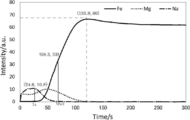
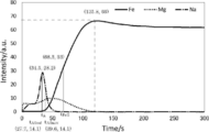
- FIG. 1 is an example of the elemental profile measured in the grain oriented electrical steel sheet of a comparative example.
- FIG. 2 is an example of the element profile measured in the grain-oriented electrical steel sheet of the present invention. 1 and 2 are both graphs showing profiles of Fe, Mg and Na.
- the sample of the grain oriented electrical steel sheet was produced as follows. First, a finish-annealed grain-oriented electrical steel sheet having a thickness of 0.23 mm manufactured by a known method is sheared to a size of 300 mm (rolling direction) x 100 mm (rolling perpendicular direction), and unreacted After removing the annealing separator, strain relief annealing was performed under the condition of N 2 atmosphere at 800 ° C. for 2 hours. A film A containing forsterite as crystalline was formed on the surface of the steel plate. Next, light acid washing was performed using a 5% by mass aqueous phosphoric acid solution. After light acid washing, in the comparative example of FIG.
- the coating amount (both sides) as NaOH was made 0.01 g / m 2 by immersing in a 10% by mass aqueous solution of NaOH at 25 ° C. for 5 seconds and then washing with water. . Thereafter, an aqueous solution obtained by mixing an aqueous solution of magnesium phosphate (100 parts by mass in terms of solid content), colloidal silica (50 parts by mass in terms of solid content), and CrO 3 (15 parts by mass) is diluted with pure water The specific gravity was adjusted to 1.20 g / cc to obtain a coating solution.
- the obtained coating solution was applied onto both sides of the coated steel sheet with a coating using a roll coater such that the coated amount after drying on both sides was 10 g / m 2 .
- the coated A-coated steel plate coated with the coating solution was loaded into a drying oven, dried at 300 ° C. for 1 minute, and then baked at 800 ° C. for 2 minutes under the condition of 100% N 2 .
- a coating B containing silica glass as glass was formed on the coating A.
- a sample of the grain-oriented electrical steel sheet (coating B / coating A / steel sheet) thus obtained was obtained.
- the half-value time t Fe / 2 of the profile of Fe is taken as the time (time on the surface side) showing a half intensity value of the intensity value of the peak. If the Fe profile does not have a peak, do as follows. First, long-time sputtering is performed, and it is waited until the sputtering reaches the steel plate (base iron) sufficiently and the emission intensity of Fe becomes a constant value.
- the time on the most surface side (film B side) indicating a half intensity value of the emission intensity (intensity value) of Fe which has become a constant value is taken as a half-value time t Fe / 2 of the profile of Fe .
- Peak time t A of the profile of alkali metal elements is the peak time when there is one peak, and the peak time of the highest peak when there are multiple peaks. I assume.
- ⁇ half-value time t A / 2 of the profile of the alkali metal element shows half the intensity value of the intensity value of the peak (if there is one peak, its peak, or the highest peak if there are multiple peaks) It will be time. Furthermore, the half value time of the surface side (coating B side) is t A / 2sur , and the half value time of the steel plate side is t A / 2met .
- t A / 2 is a concept including both t A / 2sur and t A / 2met .
- t A / t Fe / 2 is 0.35 or more and 0.75 or less, the alkali metal element is concentrated at the interface between the coating A and the coating B. In this case, the wettability of the interface between the coating A and the coating B is good, and the adhesion between the coating A and the coating B is excellent. In addition, the state in which a large amount of the alkali metal element is contained only in the film B is avoided, and the tension applied to the steel plate is excellent. Furthermore, the state in which the alkali metal element infiltrates into the film A is avoided, and the adhesion between the film A and the steel plate is excellent.
- t A / t Fe / 2 is preferably 0.40 or more and 0.75 or less.
- t A / 2sur / t Fe / 2 is less than 0.25 (that is, the profile of the alkali metal element is broad), it can be said that the alkali metal element is concentrated at the interface between the coating A and the coating B. Since the alkali metal element is mainly contained only in the film B and has the effect of improving the adhesion, the tension applied to the steel sheet is insufficient.
- t A / 2met / t Fe / 2 is larger than 1.00, the infiltration amount of the alkali metal element to the film A is large, the alkali metal element is concentrated at the crystal interface, and the grain boundary strength decreases. The adhesion between the coating A and the steel plate is poor.
- t A / 2 / t Fe / 2 (that is, both t A / 2sur / t Fe / 2 and t A / 2met / t Fe / 2 ) is 0.25 or more and 1.00 or less If it is, as in formula (1), the alkali metal element is concentrated at the interface between the coating A and the coating B. In this case, the wettability of the interface between the coating A and the coating B is good, and the adhesion between the coating A and the coating B is excellent. In addition, the state in which a large amount of the alkali metal element is contained only in the film B is avoided, and the tension applied to the steel plate is excellent.
- the state in which the alkali metal element infiltrates into the film A is avoided, and the adhesion between the film A and the steel plate is excellent. 0.30 or more and 0.90 or less are preferable for tA / 2 / tFe / 2 .
- Examples of the alkali metal element include Li, Na, K, Rb, Cs, and Fr.
- the alkali metal element that is, the alkali metal element to be concentrated at the interface between the coating A and the coating B
- the alkali metal element include Li, Na, K, Rb, Cs, and Fr.
- at least one selected from the group consisting of Li, Na, and K is preferable because it is superior in price and availability to Rb, Cs, and Fr, and the tension applied to the steel plate is higher than Li.
- at least one selected from the group consisting of Na and K is more preferable.
- the steel plate is not particularly limited.
- a steel slab to be a steel plate has, as a component in the steel, C: 0.001 to 0.10%, Si: 1.0 to 5.0%, by mass%, by mass 0.01 to 1.0%, sol. Al: 0.003 to 0.050%, N: 0.001 to 0.020%, S: 0.001 to 0.05%, and / or Se: 0.001 to 0.05% It is preferable from the viewpoint of the magnetic properties that the balance consists of inevitable enemy and Fe.
- C is a component useful for generation of Goss-oriented crystal grains, and in order to exert this effect effectively, the C content is preferably 0.001% by mass or more.
- the C content is preferably 0.10 mass% or less.
- Si is a component necessary to enhance the electrical resistance and reduce iron loss, and stabilize the BCC structure of iron to enable high temperature heat treatment, and the Si content is 1.0% by mass or more. Is preferable, and 2.0 mass% or more is more preferable.
- the content of Si is preferably 5.0% by mass or less.
- Mn not only contributes effectively to the improvement of the hot embrittlement of the steel, but also forms precipitates such as MnS and MnSe when S and Se are mixed, and functions as an inhibitor (inhibitor). Demonstrate.
- the Mn content is preferably 0.01% by mass or more.
- the Mn content is preferably 1.0% by mass or less.
- Al is a useful component that forms AlN in steel and exhibits the action of an inhibitor as a dispersed second phase.
- the Al content is preferably 0.003 to 0.050% by mass.
- N like Al, is a component for forming AlN. When N is too small, precipitation of AlN may be insufficient. On the other hand, if N is too large, blistering may occur at the time of slab heating. Therefore, the N content is preferably 0.001 to 0.020 mass%.
- S and Se combine with Mn and Cu to form MnSe, MnS, Cu 2-x Se, Cu 2-x S, etc., and are useful components that exhibit the action of an inhibitor as a dispersed second phase in steel. is there. If the amount of S and / or Se is too small, the effect of addition may be insufficient, and if too large, solid solution at the time of slab heating may be incomplete or it may cause defects on the product surface. Therefore, the content of S and / or Se is preferably 0.001 to 0.05% by mass.
- the steel slab to be a steel plate further contains, in mass%, Cu: 0.01 to 0.2%, Ni: 0.01 to 0.5%, Cr: 0.01 to 0.5%, Sb: 0. At least one selected from the group consisting of 01 to 0.1%, Sn: 0.01 to 0.5%, Mo: 0.01 to 0.5%, and Bi: 0.001 to 0.1%.
- the magnetic properties can be further improved by adding an element having an action as a supplementary inhibitor.
- the above-mentioned elements are mentioned as such an element. If any of the elements is less than the above content, the effect is hardly obtained. On the other hand, if the content is exceeded, defects in the appearance of the film and secondary recrystallization defects may easily occur. Therefore, the content is preferably in the above range.
- the steel slab to be a steel plate is, by mass%, B: 0.001 to 0.01%, Ge: 0.001 to 0.1%, As: 0.005 to 0.1 %, P: 0.005 to 0.1%, Te: 0.005 to 0.1%, Nb: 0.005 to 0.1%, Ti: 0.005 to 0.1%, and V: It can contain at least one element selected from the group consisting of 0.005 to 0.1%. Thereby, the suppression force is further strengthened, and a higher magnetic flux density can be stably obtained.
- the steel plate is manufactured, for example, as follows. First, the steel slab is subjected to hot rolling to obtain a hot-rolled sheet.
- the hot-rolled sheet is optionally subjected to hot-rolled sheet annealing, and then subjected to one or two or more cold rollings sandwiching the intermediate annealing to obtain a cold-rolled sheet having a final thickness.
- the cold rolled sheet is subjected to primary recrystallization annealing and decarburization annealing (it is common that primary recrystallization annealing also serves as decarburization annealing), and then an annealing separator is applied and then final finish annealing is applied.
- a steel plate (oriented electrical steel sheet) in which Goth-oriented crystal grains (secondary recrystallized grains) are developed is obtained.
- manufacturing conditions conventionally well-known conditions can be employ
- a forsterite-containing film is formed on the surface of the obtained steel sheet.
- a film (cordierite film) containing cordierite is formed on the surface of the obtained steel sheet.
- the forsterite film and the cordierite film correspond to the film A described later. When these films are used as the film A, the film B described later is formed as it is.
- these films are removed by pickling or the like, and then another film A (for example, a film A containing a nitride described later) is formed, and then a film described later Form B
- a directional electromagnetic steel plate (steel plate), without forming these films.
- Film A is a film containing crystalline material disposed on a steel plate.
- the method for producing the film A is not particularly limited, and methods other than those described above include, for example, CVD (Chemical Vapor Deposition) method, PVD (Physical Vapor Deposition) method, sol gel method, steel plate oxidation method and the like. It can be mentioned.
- Examples of the crystalline material of the film A include oxides, and specific examples thereof preferably include at least one selected from the group consisting of forsterite and cordierite.
- Coating A containing forsterite as a crystalline oxide is the above-described forsterite coating.
- Coating A containing cordierite as a crystalline oxide is the cordierite coating described above. The method for obtaining these coatings is as described above.
- the crystalline quality of the film A may be a nitride.
- the nitride include metal nitrides.
- the metal nitride is preferably a metal nitride containing at least one metal selected from the group consisting of Ti, Al and Cr, and is made of titanium nitride (TiN), aluminum nitride (AlN) and chromium nitride (CrN). At least one selected from the group is more preferred.
- the film A containing nitride is formed by, for example, a CVD method or a PVD method.
- the crystalline content in the film A can be measured by X-ray diffraction using a calibration curve.
- the coating A may have two or more layers.
- the film thickness on one side of the film A (in the case of two or more layers, the total film thickness of each layer) is not particularly limited, but is preferably 0.05 to 5.00 ⁇ m, and more preferably 0.10 to 3.00 ⁇ m.
- the film B is a film containing vitreous material disposed on the film A, and is a so-called insulating tension film.
- the glass of the coating B include silica phosphate glass, and specific examples thereof include Mg, Al, Ca, Ti, Nd, Mo, Cr, B, Ta, Cu and Mn.
- a preferred example is a silicon phosphate glass containing at least one selected metal element. From the viewpoint of recent environmental regulations, it is more preferable not to contain Cr.
- the coating B may contain crystalline (except for the crystalline contained in the coating A).
- the balance other than glass is crystalline.
- the vitreous content of the film B is preferably 10 to 100% by mass because the film adhesion between the film A and the film B may be degraded if the content is less than 10% by mass.
- the content of glass in the film B is more preferably 30 to 90% by mass, and still more preferably 40 to 70% by mass or more.
- the method to form the film B is not particularly limited, for example, a method (method B1) of obtaining the film B by applying a coating liquid on the film A and then baking it may be mentioned.
- the baking may be planarization annealing which also serves as baking.
- the coating solution preferably contains phosphoric acid and / or phosphate and colloidal silica.
- metal species of phosphate include Mg, Al, Ca, Mn, Ni and the like.
- the coating solution can further contain a metal compound.
- the metal species of the metal compound include at least one selected from the group consisting of Mg, Al, Ca, Ti, Nd, Mo, Cr, B, Ta, Cu and Mn.
- B (boron) is treated as a metal.
- the content of each component in the coating liquid is not particularly limited, and can be set as appropriate.
- the baking temperature is, for example, 600 to 1000 ° C.
- the baking time is, for example, 1 to 300 seconds.
- the baking atmosphere is, for example, a nitrogen atmosphere.
- the method of forming the film B may be a method (method B2) of obtaining the film B by applying a glass frit on the film A and then baking it.
- the glass frit contains, for example, PbO, SiO 2 , B 2 O 3 , BaO, ZnO or the like on an oxide basis.
- the baking temperature is, for example, 600 to 1,200.degree.
- the baking time is, for example, 5 to 20 minutes.
- the baking atmosphere is, for example, a nitrogen atmosphere.
- the coating B may have two or more layers.
- the film thickness on one side of the film B (in the case of two or more layers, the total film thickness of each layer) is preferably 1.0 to 6.0 ⁇ m, from the viewpoint of obtaining a good interlayer resistance and space factor, 1.5 It is more preferable to be -4.0 ⁇ m.
- the tension applied to the steel sheet by the film B is, for example, 8 MPa or more, preferably 10 MPa or more, and more preferably 12 MPa or more.
- the method of producing the grain oriented electrical steel sheet of the present invention is a method comprising the steps of obtaining a steel sheet with a coating A and forming a coating B on the coating A of the steel sheet with a coating A.
- the method of adjusting the profile of the alkali metal element is not particularly limited in order to satisfy the formulas (1) and (2) described above, but, for example, methods 1 to 3 described below can be mentioned.
- Method 1 is a method of immersing the steel sheet with film A in an aqueous solution of an alkali metal compound, and then washing with water and drying before forming the film B. At this time, the profile of the alkali metal element is adjusted by adjusting the washing conditions such as the washing time.
- alkali metal compound examples include, but are not limited to, for example, LiOH, NaOH, KOH, Li 2 SO 4 , Na 2 SO 4 , K 2 SO 4 , LiCl, NaCl, Na 2 HPO 4 , K 2 HPO 4 and the like. Can be mentioned.
- the content of the alkali metal compound in the aqueous solution in which the coated steel sheet with a coating A is immersed is preferably 1% by mass or more, and more preferably 5% by mass or more, because the basis weight described later can be easily obtained.
- the content is preferably 40% by mass or less, more preferably 30% by mass or less, because the amount of removal of the alkali metal compound by washing with water is not too large and is economical.
- the temperature of the aqueous solution of the alkali metal compound for immersing the coated steel A-coated steel sheet is preferably 10 ° C. or higher, and more preferably 15 ° C. or higher because the basis weight described later can be easily obtained.
- this temperature is preferably 80 ° C. or less, more preferably 70 ° C. or less, because anions such as OH ⁇ , SO 4 2 ⁇ and Cl ⁇ of the alkali metal compound are less likely to corrode the coating A and the steel plate.
- the time (immersion time) for immersing the steel sheet with film A in an aqueous solution of an alkali metal compound is not particularly limited, and is, for example, 1 to 60 seconds, preferably 5 to 30 seconds.
- the coating weight of the alkali metal compound in terms of alkali metal element in the coated A-coated steel sheet after drying is, for example, 1.0 ⁇ 10 ⁇ 6 mol / m 2 or more on both sides, and the coating adhesion becomes better. For this reason, 1.0 ⁇ 10 ⁇ 5 mol / m 2 or more is preferable.
- the upper limit of the coating weight is not particularly limited, but is, for example, 1.0 ⁇ 10 ⁇ 2 mol / m 2 or less.
- the weight per unit area of the alkali metal compound in terms of an alkali metal element can be obtained from the mass change of the coated steel sheet A before and after treatment (immersion in an aqueous solution of alkali metal compound, water washing and drying).
- a calibration curve is created from the fluorescent X-ray counts of the alkali metal element.
- the basis weight of the above alkali metal compound in terms of alkali metal element can be simply measured.
- a coating solution or the like is applied and baked on the film A to form a film B.
- the baking conditions such as the baking time of the film B, the diffusion of the alkali metal element can be controlled, and the distribution of the alkali metal element can be adjusted.
- Method 2 is a method in which a coating solution B is applied and baked multiple times to form a plurality of layers of film B on the film A.
- Colloidal silica used for a coating liquid may contain alkali metal elements, such as Na.
- the amount of alkali metal element of colloidal silica used for the coating B of the first layer is made larger than that of the second layer. Thereby, the profile of the alkali metal element is adjusted to satisfy the above-mentioned formulas (1) and (2).
- Method 3 is a method of forming a plurality of coatings B on the coating A by applying and baking a glass frit a plurality of times.
- an alkali metal compound such as KOH or NaOH is added to the glass frit used for the first coating film B.
- the profile of the alkali metal element is adjusted to satisfy the above-mentioned formulas (1) and (2).
- Si 3.3%, C: 0.06%, Mn: 0.08%, S: 0.001%, Al: 0.015%, N: 0.006%, Cu:
- a silicon steel slab containing 0.05% and Sb: 0.01% was prepared.
- the silicon steel slab was heated at 1100 ° C. for 30 minutes and then subjected to hot rolling to obtain a hot-rolled sheet having a thickness of 2.2 mm.
- the obtained hot-rolled sheet was subjected to annealing at 1000 ° C. for 1 minute and then subjected to cold rolling to obtain a cold-rolled sheet coil having a final thickness of 0.27 mm.
- a cold-rolled sheet sample having a size of 100 mm (in the direction perpendicular to rolling) ⁇ 400 mm (in the direction of rolling) was collected.
- the collected cold rolled sheet sample was heated from room temperature to 820 ° C. in a laboratory at a heating rate of 20 ° C./s, and subjected to primary recrystallization annealing at 820 ° C. for 60 seconds in a wet atmosphere.
- an annealing separator in which 10 parts by mass of TiO 2 was mixed with 100 parts by mass of MgO was applied on the surface of the cold-rolled sheet sample subjected to primary recrystallization annealing after making it into a water slurry, and then dried. After raising the temperature of the cold-rolled sheet sample after drying between 300 ° C. and 800 ° C. over 100 hours, the temperature is raised to 1200 ° C. at 50 ° C./hr, and final annealing is performed at 1200 ° C. for 5 hours I did. Thus, a film A (forsterite film) containing forsterite as a crystalline substance was formed, and a steel plate with the film A was obtained. The film thickness of the film A (forsterite film) was 1.20 ⁇ m. The crystalline content of the coating A was 80% by mass or more.
- the obtained steel sheet with film A was immersed in a 5% by mass aqueous solution of an alkali metal compound described in Table 1 below at 25 ° C. for 10 seconds. Thereafter, it was washed with pure water and dried. At this time, by adjusting the degree of washing with water, the coated amount (both sides) in terms of alkali metal element of the alkali metal compound after drying was adjusted. The basis weight was measured by the method described above.
- a silica phosphate-based insulation tension containing magnesium phosphate (30 mol% in Mg (PO 3 ) 2 conversion), colloidal silica (60 mol% in SiO 2 conversion), and CrO 3 (10 mol%) A coating solution was prepared.
- the prepared coating solution was applied onto film A and baked at 850 ° C. Thereby, on the film A, a film B containing silica glass as glass was formed. At this time, the baking time (unit: s (seconds)) described in Table 1 below was used.
- colloidal silica colloidal silica “Snowtex-O” (Na content: 0.03 mass%) manufactured by Nissan Chemical Industries, Ltd., which is an acidic type having a low Na content, was used.
- the amount of coating solution applied was 10 g / m 2 on both sides.
- the film thickness of the film B was 2.5 ⁇ m on one side.
- ⁇ Covering width A sample of the produced grain oriented electrical steel sheet was sheared in the thickness direction using a shearing machine. Thereafter, the processing end is observed using a metallurgical microscope, and the distance (the distance from the processing end face) at which the coating (at least one of the coatings A and B) is peeled off at the processing end is measured. It was set as the film peeling width (unit: mm) of the part. It can be evaluated that the film adhesion is excellent as the film peeling width is smaller, and for practical use, the film peeling width is preferably less than 3.0 mm.
- Bending peeling diameter A strain relief annealing was performed in a nitrogen atmosphere at 800 ° C. for 3 hours on a sample of the produced grain-oriented electrical steel sheet. Thereafter, the sample was wound around a plurality of round bars having different diameters in units of 10 mm, and the minimum diameter (bending peeling diameter) at which peeling or cracking did not occur in the coating (at least one of the coating A and B) was determined. It can be evaluated that the smaller the bending peeling diameter (unit: mm), the better the film adhesion, and the practically preferable bending peeling diameter is less than 40 mm.
- ⁇ tension applied ⁇ tension applied >> First, a corrosion prevention tape was attached to one side (entire surface) of a sample of the produced grain-oriented electrical steel sheet. Thereafter, the sample with the corrosion prevention tape attached thereto was immersed in a 25% by mass aqueous NaOH solution at 110 ° C. for about 10 minutes to remove the coating B on the side to which the corrosion prevention tape was not attached. By removing the coating B on one side, the sample warped. The corrosion protection tape was removed and the radius of curvature of the sample was measured. The applied tension (unit: MPa) to the steel plate by the coating B was determined from the measured radius of curvature. The applied tension is preferably 8.0 MPa or more.
- No. 2 had a large film peeling width and bending peeling diameter, and had poor film adhesion.
- the tension applied to the steel plate was insufficient.
- No. 12 had a large film peeling width and bending peeling diameter, and had poor film adhesion.
- the prepared coating solution was applied to the surface of the obtained coated A-coated steel sheet and baked.
- the application and baking were performed twice.
- the colloidal silica of the coating solution colloidal silica “AT-300” (Na content: 0.55% by mass) manufactured by Adeka is used for the first coating B, and the second coating B is used.
- colloidal silica "AT-20N” (Na content: 0.03% by mass) manufactured by ADEKA Corporation was used.
- the baking conditions of the film B were a nitrogen atmosphere for 30 seconds at 900 ° C. for both the first and second layers.
- the film thickness (one side, unit: ⁇ m) of the film B was as described in Table 2 below. The film thickness was evaluated by cross-sectional SEM observation.
- a silicon steel slab containing 0.05% and Sb: 0.01% was prepared.
- the silicon steel slab was heated at 1100 ° C. for 30 minutes and then subjected to hot rolling to obtain a hot-rolled sheet having a thickness of 2.2 mm.
- the obtained hot-rolled sheet was annealed at 1000 ° C. for 1 minute and then cold-rolled to obtain a cold-rolled sheet having a final thickness of 0.23 mm. Subsequently, the cold rolled sheet was heated from room temperature to 820 ° C.
- annealing in which 150 parts by mass of Al 2 O 3 and 1 part by mass of Na 2 B 4 O 7 ⁇ 10H 2 O are mixed with 50 parts by mass of MgO.
- the separating agent was slurried in water, then applied and dried. After raising the temperature of the cold rolled sheet after drying between 300 ° C. and 800 ° C. over 100 hours, the temperature is raised to 1200 ° C.
- cordierite as crystalline (2MgO ⁇ 2Al 2 O 3 ⁇ 5SiO 2) steel plates with coating A comprising (coil). From the center of the obtained coil, a sample having a size of 100 mm (in the direction perpendicular to rolling) ⁇ 400 mm (in the direction of rolling) was taken. In some samples, the film A (cordierite film) was peeled off using a mixed acid of sulfuric acid and hydrofluoric acid, and a film A containing a nitride shown in Table 3 below as crystalline using a PVD method The nitride film was formed. The film thickness (unit: ⁇ m) of the film A is shown in Table 3 below. The crystalline content in the film A was 80% by mass or more in all cases.
- a glass frit manufactured by Asahi Glass Co., Ltd. described in Table 3 below was applied onto the surface of the steel sheet with the coating A, and the coating B was formed by baking.
- the glass frit had a large particle size, and was ground using a ball mill to adjust the particle size to an average particle size of 1.0 ⁇ m before use.
- the application and baking were performed twice to form a two-layer film B.
- 0.2 mass% KOH was added to a glass frit.
- the baking conditions of the film B were a nitrogen atmosphere for 10 minutes at 1000 ° C. in both the first and second layers.
- the film thickness (one side, unit: ⁇ m) of the film B was as described in Table 3 below. The film thickness was evaluated by cross-sectional SEM observation.
Landscapes
- Chemical & Material Sciences (AREA)
- Engineering & Computer Science (AREA)
- Mechanical Engineering (AREA)
- Materials Engineering (AREA)
- Metallurgy (AREA)
- Organic Chemistry (AREA)
- Chemical Kinetics & Catalysis (AREA)
- General Chemical & Material Sciences (AREA)
- Physics & Mathematics (AREA)
- Thermal Sciences (AREA)
- Crystallography & Structural Chemistry (AREA)
- Inorganic Chemistry (AREA)
- Electromagnetism (AREA)
- Power Engineering (AREA)
- Dispersion Chemistry (AREA)
- Manufacturing & Machinery (AREA)
- Ceramic Engineering (AREA)
- Chemical Treatment Of Metals (AREA)
- Soft Magnetic Materials (AREA)
- Manufacturing Of Steel Electrode Plates (AREA)
Abstract
Description
これらの被膜は、高温で形成され、しかも鋼板と比較して低い熱膨張率を持つことから、室温まで下がったときの鋼板と被膜との熱膨張率の差異により鋼板に張力が付与され、鉄損が低減する。例えば、8MPa以上(特許文献1の[請求項2]を参照)という高い張力を鋼板に付与することが要求される場合がある。
更に、より高張力な被膜を形成して磁気特性を向上させる技術として、例えば、特許文献4には、コロイド状シリカのガラス転移点を適正化する技術が提案されている。
具体的には、このような方向性電磁鋼板に対して、せん断加工やスリット加工などの歪速度の速い加工を施した。その結果、加工端部において被膜が剥離する場合があった。この場合、被膜密着性が良好であると評価され得ない。加工端部の被膜剥離幅が大きいと、粉塵発生などの作業環境の悪化が生じたり、方向性電磁鋼板を積層したときに導通が生じたりするおそれがある。
まず、加工端部を詳細に調査したところ、被膜Aと被膜Bとの界面を起点として被膜剥離が生じている場合が多かった。この調査結果に基づいて検討を重ねた結果、被膜Bにアルカリ金属元素を多く含有させることにより、被膜Bの焼付中の軟化が促進し(つまり粘性が低下し)、被膜Aと被膜Bとの界面の濡れ性が増して、被膜Aと被膜Bとの密着性が向上することが見出された。
しかし、特許文献4の段落[0023]に記載されているように、アルカリ金属元素の添加は、コロイド状シリカのガラス転移温度を低下させ、鋼板への付与張力の低下を招くおそれがある。
そこで、更に検討した結果、被膜Aと被膜Bとの界面にアルカリ金属元素を濃化させることにより、鋼板への付与張力の低下を回避できることを見出し、本発明を完成させた。
[1]鋼板と、上記鋼板上に配置された結晶質を含む被膜Aと、上記被膜A上に配置されたガラス質を含む被膜Bと、を備える方向性電磁鋼板であって、高周波グロー放電発光表面分析法を用いて得られる、上記被膜Bから上記鋼板に向かう方向の元素プロファイルが、下記式(1)および(2)を満たす、方向性電磁鋼板。
0.35≦(tA/tFe/2)≦0.75・・・(1)
0.25≦(tA/2/tFe/2)≦1.00・・・(2)
ただし、tAはアルカリ金属元素のプロファイルのピーク時間、tA/2はアルカリ金属元素のプロファイルの半価時間、tFe/2はFeのプロファイルの半価時間を示す。
[2]上記被膜Aが含む上記結晶質が、酸化物である、上記[1]に記載の方向性電磁鋼板。
[3]上記酸化物が、フォルステライトおよびコーディエライトからなる群から選ばれる少なくとも1種である、上記[2]に記載の方向性電磁鋼板。
[4]上記被膜Aが含む上記結晶質が、窒化物である、上記[1]に記載の方向性電磁鋼板。
[5]上記窒化物が、窒化チタン、窒化アルミニウムおよび窒化クロムからなる群から選ばれる少なくとも1種である、上記[4]に記載の方向性電磁鋼板。
[6]上記被膜Bが含む上記ガラス質が、珪リン酸塩ガラスである、上記[1]~[5]のいずれかに記載の方向性電磁鋼板。
[7]上記珪リン酸塩ガラスが、Mg、Al、Ca、Ti、Nd、Mo、Cr、B、Ta、CuおよびMnからなる群から選ばれる少なくとも1種の金属元素を含む珪リン酸塩ガラスである、上記[6]に記載の方向性電磁鋼板。
[8]上記アルカリ金属元素が、NaおよびKからなる群から選ばれる少なくとも1種である、上記[1]~[7]のいずれかに記載の方向性電磁鋼板。
[9]上記[1]~[8]のいずれかに記載の方向性電磁鋼板を製造する方法であって、上記鋼板上に上記被膜Aが配置された被膜A付き鋼板を得る工程と、上記被膜A付き鋼板の上記被膜A上に、上記被膜Bを形成する工程と、を備え、上記被膜Bを形成する前に、上記被膜A付き鋼板を、アルカリ金属化合物の水溶液に浸漬し、その後、水洗し、乾燥し、上記乾燥後の上記被膜A付き鋼板における、上記アルカリ金属化合物のアルカリ金属元素換算の目付量が、両面で、1.0×10⁻⁵mol/m2以上である、方向性電磁鋼板の製造方法。
[10]上記目付量が、1.0×10⁻²mol/m2以下である、上記[9]に記載の方向性電磁鋼板の製造方法。
本発明の方向性電磁鋼板は、鋼板と、上記鋼板上に配置された結晶質を含む被膜Aと、上記被膜A上に配置されたガラス質を含む被膜Bと、を備える方向性電磁鋼板であって、高周波グロー放電発光表面分析法を用いて得られる、上記被膜Bから上記鋼板に向かう方向の元素プロファイルが、下記式(1)および(2)を満たす、方向性電磁鋼板である。
0.35≦(tA/tFe/2)≦0.75・・・(1)
0.25≦(tA/2/tFe/2)≦1.00・・・(2)
ただし、tAはアルカリ金属元素のプロファイルのピーク時間、tA/2はアルカリ金属元素のプロファイルの半価時間、tFe/2はFeのプロファイルの半価時間を示す。
以下、本発明の方向性電磁鋼板を、より詳細に説明する。まず、元素プロファイルについて説明した後、各構成(鋼板、被膜Aおよび被膜B)を説明する。以下の説明は、本発明の方向性電磁鋼板を製造する方法の説明も兼ねる。
被膜Bから鋼板に向かう方向(「板厚方向」ともいう)の元素プロファイルは、高周波グロー放電発光表面分析(rf-GD-OES)法を用いて測定する。
具体的には、堀場製作所社製のマーカス型高周波グロー放電発光表面分析装置「GD-Profiler2」を用い、プラズマガスとしてAr100%を用い、ガス圧力:600Pa、高周波出力:35W、測定間隔:0.1秒/点の条件にて測定する。
図1は、比較例の方向性電磁鋼板において測定した元素プロファイルの一例である。図2は、本発明の方向性電磁鋼板において測定した元素プロファイルの一例である。図1および図2は、いずれも、Fe、MgおよびNaのプロファイルを示すグラフである。
まず、公知の方法で製造された、板厚が0.23mmである仕上げ焼鈍済みの方向性電磁鋼板を、300mm(圧延方向)×100mm(圧延直角方向)の大きさにせん断し、未反応の焼鈍分離剤を除去した後、800℃、2時間、N2雰囲気の条件で、歪取焼鈍を施した。鋼板の表面には、結晶質としてフォルステライトを含む被膜Aが形成されていた。
次に、5質量%リン酸水溶液を用いて軽酸洗した。軽酸洗の後、図1の比較例においては、未処理とした。一方、図2の本発明においては、NaOHの10質量%水溶液に25℃で5秒間浸漬し、その後、水洗することにより、NaOHとしての目付量(両面)を、0.01g/m2とした。
その後、リン酸マグネシウム水溶液(固形分換算で100質量部)と、コロイド状シリカ(固形分換算で50質量部)と、CrO3(15質量部)とを混合した水溶液を、純水で希釈して比重1.20g/ccに調整して、コーティング液を得た。得られたコーティング液を、被膜A付き鋼板の両面に、両面の乾燥後の塗布量が10g/m2となるように、ロールコーターを用いて、塗布した。
コーティング液を塗布した被膜A付き鋼板を、乾燥炉に装入して、300℃で1分間乾燥し、その後、800℃、2分間、N2100%の条件で焼付した。焼付により、被膜A上に、ガラス質として珪リン酸塩ガラスを含む被膜Bが形成された。
このようにして得られた方向性電磁鋼板(被膜B/被膜A/鋼板)の試料を得た。
Feのプロファイルの半価時間tFe/2は、Feのプロファイルがピークを持つ場合は、そのピークの強度値の2分の1強度値を示す時間(表面側の時間)とする。
Feのプロファイルがピークを持たない場合は、次のようにする。まず、長時間のスパッタを行ない、スパッタが十分に鋼板(地鉄)に到達し、Feの発光強度が一定値となるのを待つ。そして、一定値となったFeの発光強度(強度値)の2分の1強度値を示す最も表面側(被膜B側)の時間を、Feのプロファイルの半価時間tFe/2とする。
アルカリ金属元素(以下、「A」と表記する場合がある)のプロファイルのピーク時間tAは、ピークが1つの場合はそのピーク時間とし、複数のピークが存在する場合は最も高いピークのピーク時間とする。
アルカリ金属元素のプロファイルの半価時間tA/2は、ピーク(ピークが1つの場合はそのピーク、複数のピークが存在する場合は最も高いピーク)の強度値の2分の1強度値を示す時間とする。更に、表面側(被膜B側)の半価時間をtA/2sur、鋼板側の半価時間をtA/2metとする。tA/2は、tA/2surおよびtA/2metの両方を含む概念である。
式(1):0.35≦(tA/tFe/2)≦0.75について説明する。
tA/tFe/2が0.35未満である場合、アルカリ金属元素は被膜Aと被膜Bとの界面に濃化しておらず主に被膜Bのみに含まれ、鋼板への付与張力が不十分となる。
tA/tFe/2が0.75よりも大きい場合、アルカリ金属元素は被膜Aに浸潤して結晶界面に濃化した状態となり、粒界強度が低下し、被膜Aと鋼板との密着性が劣る。
tA/tFe/2は、0.40以上0.75以下が好ましい。
式(2):0.25≦(tA/2/tFe/2)≦1.00について説明する。
上述したように、tA/2は、tA/2surおよびtA/2metの両方を含む概念である。tA/2sur/tFe/2、および、tA/2met/tFe/2のどちらもが、0.25以上1.00以下であることを要する。
tA/2sur/tFe/2が0.25未満である(すなわち、アルカリ金属元素のプロファイルがブロードである)場合、アルカリ金属元素が被膜Aと被膜Bとの界面に濃化しているといえず、アルカリ金属元素は主として被膜Bのみに含まれており、密着性向上の効果はあるが、鋼板への付与張力が不十分となる。
tA/2met/tFe/2が1.00よりも大きい場合、アルカリ金属元素の被膜Aへの浸潤量が大きく、結晶界面にアルカリ金属元素が濃化した状態となり、粒界強度が低下し、被膜Aと鋼板との密着性が劣る。
tA/2/tFe/2は、0.30以上0.90以下が好ましい。
アルカリ金属元素(すなわち、被膜Aと被膜Bとの界面に濃化させるアルカリ金属元素)としては、Li、Na、K、Rb、Cs、Frが挙げられる。
これらのうち、Rb、Cs、Frよりも価格や入手性が優れるという理由から、Li、NaおよびKからなる群から選ばれる少なくとも1種が好ましく、Liよりも鋼板への付与張力が高いという理由から、NaおよびKからなる群から選ばれる少なくとも1種がより好ましい。
次に、本発明の方向性電磁鋼板の各構成(鋼板、被膜Aおよび被膜B)を説明する。
鋼板としては、特に限定されないが、例えば、鋼板となる鋼スラブは、鋼中成分として、質量%で、C:0.001~0.10%、Si:1.0~5.0%、Mn:0.01~1.0%、sol.Al:0.003~0.050%、N:0.001~0.020%、S:0.001~0.05%、および/または、Se:0.001~0.05%を含有し、残部は不可避敵不十分およびFeからなることが、磁気特性の観点から好ましい。
Siは、電気抵抗を高めて鉄損を低下させるとともに、鉄のBCC組織を安定化させて高温の熱処理を可能とするために必要な成分であり、Si含有量は、1.0質量%以上が好ましく、2.0質量%以上がより好ましい。一方、Siが多すぎると、冷間圧延が困難になる場合があることから、Si含有量は、5.0質量%以下が好ましい。
Mnは、鋼の熱間脆性の改善に有効に寄与するだけでなく、SやSeが混在している場合には、MnSやMnSe等の析出物を形成し、抑制剤(インヒビター)としての機能を発揮する。この効果を十分に得る観点から、Mn含有量は、0.01質量%以上が好ましい。一方、Mnが多すぎると、MnSe等の析出物の粒径が粗大化してインヒビターとしての効果が失われる場合があることから、Mn含有量は、1.0質量%以下が好ましい。
Alは、鋼中でAlNを形成して分散第二相としてインヒビターの作用を発揮する有用成分である。Alが少なすぎると十分に析出量が確保できない場合がある。一方、Alが多すぎるとAlNが粗大に析出してインヒビターとしての作用が失われる場合がある。このため、sol.Al含有量は、0.003~0.050質量%が好ましい。
Nは、Alと同様に、AlNを形成するための成分である。Nが少なすぎるとAlNの析出が不十分となる場合がある。一方、Nが多すぎるとスラブ加熱時にふくれ等を生じる場合がある。このため、N含有量は、0.001~0.020質量%が好ましい。
SおよびSeは、MnやCuと結合して、MnSe、MnS、Cu2-xSe、Cu2-xS等を形成し、鋼中の分散第二相としてインヒビターの作用を発揮する有用成分である。Sおよび/またはSeが少なすぎると添加効果に不十分な場合があり、多すぎるとスラブ加熱時の固溶が不完全となったり、製品表面の欠陥の原因となったりする場合がある。このため、Sおよび/またはSeの含有量は、0.001~0.05質量%が好ましい。
まず、上記鋼スラブに、熱間圧延を施して熱延板を得る。熱延板に、必要に応じて熱延板焼鈍を施した後、1回または中間焼鈍を挟む2回以上の冷間圧延を施して、最終板厚の冷延板を得る。冷延板に、一次再結晶焼鈍および脱炭焼鈍(一次再結晶焼鈍が脱炭焼鈍を兼ねるのが一般的である)を施し、その後、焼鈍分離剤を塗布してから、最終仕上げ焼鈍を施す。こうして、ゴス方位の結晶粒(二次再結晶粒)が発達した鋼板(方向性電磁鋼板)が得られる。製造条件としては、従来公知の条件を採用でき、特に限定されない。
例えば、Al2O3を主成分とする焼鈍分離剤を用いることにより、得られる鋼板の表面には、コーディエライトを含有する被膜(コーディエライト被膜)が形成される。
フォルステライト被膜およびコーディエライト被膜は、後述する被膜Aに相当する。
これらの被膜を被膜Aとして使用する場合は、そのまま後述する被膜Bを形成する。
これらの被膜を被膜Aとして使用しない場合は、これらの被膜Aを酸洗等によって除去した後、別の被膜A(例えば、後述する窒化物を含む被膜A)を形成し、その後、後述する被膜Bを形成する。
これらの被膜を形成させずに、方向性電磁鋼板(鋼板)を製造してもよい。
被膜Aは、鋼板上に配置された、結晶質を含む被膜である。被膜Aの製造方法としては、特に限定されず、上述した方法以外の方法としては、例えば、CVD(Chemical Vapor Deposition)法、PVD(Physical Vapor Deposition)法、ゾルゲル法、鋼板酸化法などの方法が挙げられる。
窒化物を含む被膜Aは、例えば、CVD法またはPVD法により形成される。
被膜Aにおける結晶質の含有量は、検量線を用いたX線回折により測定できる。
被膜Aの片面の膜厚(2層以上の場合は、各層の合計の膜厚)は、特に限定されないが、0.05~5.00μmが好ましく、0.10~3.00μmがより好ましい。
被膜Bは、被膜A上に配置されたガラス質を含む被膜であり、いわゆる絶縁張力被膜である。
被膜Bのガラス質としては、例えば、珪リン酸塩ガラスが挙げられ、その具体例としては、Mg、Al、Ca、Ti、Nd、Mo、Cr、B、Ta、CuおよびMnからなる群から選ばれる少なくとも1種の金属元素を含む珪リン酸塩ガラスが好適に挙げられる。近年の環境規制の観点からは、Crを含有しないことがより好ましい。
被膜Bにおけるガラス質の含有量は、10質量%未満であると被膜Aと被膜Bとの被膜密着性が劣化する場合があることから、10~100質量%が好ましい。
また、ガラス質の中に結晶質を含ませて結晶化ガラスとすることにより、ガラス質単独では得られない特性(例えば、低熱膨張性、高耐熱性など)を付与できる。このため、被膜Bにおけるガラス質の含有量は、30~90質量%がより好ましく、40~70質量%以上が更に好ましい。
被膜Bを形成する方法が、後述する方法B1または方法B2である場合、形成される被膜Bにおけるガラス質の含有量は、10質量%以上であるとみなすことができる。
コーティング液は、リン酸および/またはリン酸塩と、コロイド状シリカとを含有することが好ましい。リン酸塩の金属種としては、例えば、Mg、Al、Ca、Mn、Niなどが挙げられる。
コーティング液は、更に、金属化合物を含有できる。金属化合物の金属種としては、例えば、Mg、Al、Ca、Ti、Nd、Mo、Cr、B、Ta、CuおよびMnからなる群から選ばれる少なくとも1種が挙げられる。B(ホウ素)は金属として扱う。
コーティング液中の各成分の含有量は、特に限定されず、適宜設定できる。
コーティング液を用いる場合、焼付温度は、例えば600~1000℃である。焼付時間は、例えば1~300秒間である。焼付雰囲気は、例えば窒素雰囲気である。
ガラスフリットは、例えば、酸化物基準で、PbO、SiO2、B2O3、BaO、ZnOなどを含有する。
ガラスフリットを用いる場合、焼付温度は、例えば600~1200℃である。焼付時間は、例えば5~20分間である。焼付雰囲気は、例えば窒素雰囲気である。
被膜Bの片面の膜厚(2層以上の場合は、各層の合計の膜厚)は、良好な層間抵抗および占積率を得る観点から、1.0~6.0μmが好ましく、1.5~4.0μmがより好ましい。
本発明の方向性電磁鋼板を製造する方法は、概略的には、被膜A付き鋼板を得る工程と、被膜A付き鋼板の被膜A上に被膜Bを形成する工程と、を備える方法である。
このとき、上述した式(1)および(2)を満たすようにするため、アルカリ金属元素のプロファイルを調整する方法は、特に限定されないが、例えば、以下に説明する方法1~3が挙げられる。
方法1は、被膜Bを形成する前に、被膜A付き鋼板を、アルカリ金属化合物の水溶液に浸漬し、その後、水洗し、乾燥する方法である。このとき、水洗時間などの水洗条件を調整することにより、アルカリ金属元素のプロファイルを調整する。
目付量の上限は、特に限定されないが、例えば、1.0×10⁻²mol/m2以下である。
方法2は、コーティング液の塗布および焼付を複数回行ない、被膜A上に、複数層の被膜Bを形成する方法である。コーティング液に用いるコロイド状シリカは、Naなどのアルカリ金属元素を含有する場合がある。方法2においては、例えば、1層目の被膜Bに用いるコロイド状シリカのアルカリ金属元素量を、2層目のそれよりも多くする。これにより、アルカリ金属元素のプロファイルを調整して、上述した式(1)および(2)を満たすようにする。
方法3は、ガラスフリットの塗布および焼付を複数回行ない、被膜A上に、複数層の被膜Bを形成する方法である。方法3においては、1層目の被膜Bに用いるガラスフリットに、KOH、NaOHなどアルカリ金属化合物を添加する。これにより、アルカリ金属元素のプロファイルを調整して、上述した式(1)および(2)を満たすようにする。
〈方向性電磁鋼板の作製〉
以下に説明するようにして、鋼板上に被膜Aおよび被膜Bをこの順に有する方向性電磁鋼板の試料を作製した。
この珪素鋼スラブに、1100℃で30分間の加熱を施した後、熱間圧延を施して、2.2mmの板厚の熱延板を得た。得られた熱延板に、1000℃で1分間の焼鈍を施した後、冷間圧延を施して、0.27mmの最終板厚の冷延板コイルを得た。得られた冷延板コイルの中央部から、100mm(圧延直角方向)×400mm(圧延方向)のサイズの冷延板試料を採取した。採取した冷延板試料を、ラボにて室温から820℃まで加熱速度20℃/sで昇温させ、湿潤雰囲気下で820℃60秒間の一次再結晶焼鈍を施した。次いで、一次再結晶焼鈍を施した冷延板試料の表面に、MgO100質量部に対して10質量部のTiO2を混合した焼鈍分離剤を、水スラリ状にしてから塗布し、乾燥した。乾燥後の冷延板試料を、300℃から800℃の間を100時間かけて昇温させた後、1200℃まで50℃/hrで昇温させ、1200℃で5時間焼鈍する最終仕上げ焼鈍を行なった。これにより、結晶質としてフォルステライトを含む被膜A(フォルステライト被膜)を形成し、被膜A付きの鋼板を得た。被膜A(フォルステライト被膜)の膜厚は、1.20μmであった。被膜Aにおける結晶質の含有量は80質量%以上であった。
このとき、下記表1に記載された焼付時間(単位:s(秒))とした。
コロイド状シリカとしては、Na含有量が少ない酸性タイプである、日産化学社製のコロイド状シリカ「スノーテックス-O」(Na含有量:0.03質量%)を使用した。
コーティング液の塗布量は、両面で10g/m2とした。
被膜Bの膜厚は、片面2.5μmであった。
作製した方向性電磁鋼板の試料について、堀場製作所社製の「GD-Profiler2」を用い、上述した条件にて、板厚方向の元素プロファイルを測定した。測定結果から、Feのプロファイルの半価時間tFe/2、ならびに、アルカリ金属元素(A:Li、Na、K)のプロファイルのピーク時間tAおよび半価時間tA/2(tA/2sur、tA/2met)を求めた。更に、tA/tFe/2、tA/2sur/tFe/2、および、tA/2met/tFe/2を求めた。結果を下記表1に示す。
作製した方向性電磁鋼板の試料を、以下のように評価した。結果を下記表1に示す。
作製した方向性電磁鋼板の試料を、せん断機を用いて板厚方向にせん断加工した。その後、金属顕微鏡を用いて加工端部を観察し、加工端部において被膜(被膜AおよびBの少なくともいずれか)が剥離している距離(加工端面からの距離)を測定し、これを加工端部の被膜剥離幅(単位:mm)とした。
被膜剥離幅が小さいほど被膜密着性に優れると評価でき、実用上、被膜剥離幅は3.0mm未満が好ましい。
作製した方向性電磁鋼板の試料に対して、800℃で3時間、窒素雰囲気で歪取焼鈍を施した。その後、試料を、10mm単位で直径が異なる複数の丸棒に巻き付けて、被膜(被膜AおよびBの少なくともいずれか)に剥離やクラックが発生しない最小径(曲げ剥離径)を求めた。曲げ剥離径(単位:mm)が小さいほど被膜密着性に優れると評価でき、実用上、曲げ剥離径は40mm未満が好ましい。
まず、作製した方向性電磁鋼板の試料の片面(全面)に、腐食防止テープを貼り付けた。その後、腐食防止テープを貼り付けた試料を、110℃の25質量%NaOH水溶液に、10分間程度、浸漬させることにより、腐食防止テープを貼り付けていない側の面の被膜Bを除去した。片面側の被膜Bが除去されたことにより、試料には反りが生じた。腐食防止テープを除去し、試料の曲率半径を測定した。測定した曲率半径から、被膜Bによる鋼板への付与張力(単位:MPa)を求めた。
付与張力は、8.0MPa以上が好ましい。

更に、アルカリ金属化合物のアルカリ金属元素換算の目付量(両面)が、1.0×10⁻⁵mol/m2以上である場合には、被膜剥離幅が1.0mm以下となり、被膜密着性がより良好であることが分かった。
0.35≦(tA/tFe/2)および0.25≦(tA/2surtFe/2)を満たさないNo.10は、鋼板への付与張力が不十分であった。
(tA/2tFe/2)≦1.00を満たさないNo.12は、被膜剥離幅および曲げ剥離径が大きく被膜密着性が劣っていた。
0.25≦(tA/2surtFe/2)を満たさないNo.14、17および23は、鋼板への付与張力が不十分であった。
〈方向性電磁鋼板の作製〉
以下に説明するようにして、鋼板上に被膜Aおよび被膜Bをこの順に有する方向性電磁鋼板の試料を作製した。
まず、試験例1と同様にして、被膜A(フォルステライト被膜)付き鋼板を得た。
次いで、リン酸と、コロイド状シリカと、金属化合物とを含有するコーティング液を調製した。リン酸の含有量は、P2O5換算で0.5mol/Lとした。コロイド状シリカの含有量は、SiO2換算で1.5mol/Lとした。金属化合物の含有量は、下記表2に記載の金属酸化物換算で、同表に示す含有量(単位:mol/L)とした。
調製したコーティング液を、得られた被膜A付き鋼板の表面に塗布し、焼付した。塗布および焼付は2回行なった。これにより、被膜A上に、ガラス質として珪リン酸塩ガラスを含む被膜Bを2層形成した。
コーティング液のコロイド状シリカとして、1層目の被膜Bには、ADEKA社製のコロイド状シリカ「AT-300」(Na含有量:0.55質量%)を使用し、2層目の被膜Bには、ADEKA社製のコロイド状シリカ「AT-20N」(Na含有量:0.03質量%)を使用した。
被膜Bの焼付条件は、1層目および2層目ともに、900℃で30秒間、窒素雰囲気下とした。
被膜Bの膜厚(片面、単位:μm)は、下記表2に記載のとおりとした。膜厚は、断面SEM観察にて評価した。
作製した方向性電磁鋼板の試料について、試験例1と同様にして、Feのプロファイルの半価時間tFe/2、ならびに、アルカリ金属元素(Na)のプロファイルのピーク時間tAおよび半価時間tA/2(tA/2sur、tA/2met)を求めた。更に、tA/tFe/2、tA/2sur/tFe/2、および、tA/2met/tFe/2を求めた。結果を下記表2に示す。
作製した方向性電磁鋼板の試料について、試験例1と同様にして、被膜剥離幅、曲げ剥離径および付与張力を求めた。結果を下記表2に示す。
更に、作製した方向性電磁鋼板の試料について、JIS C 2550に準拠して、層間抵抗および占積率を測定した。層間抵抗は、電流値(フランクリン電流値)により評価した。結果を下記表2に示す。
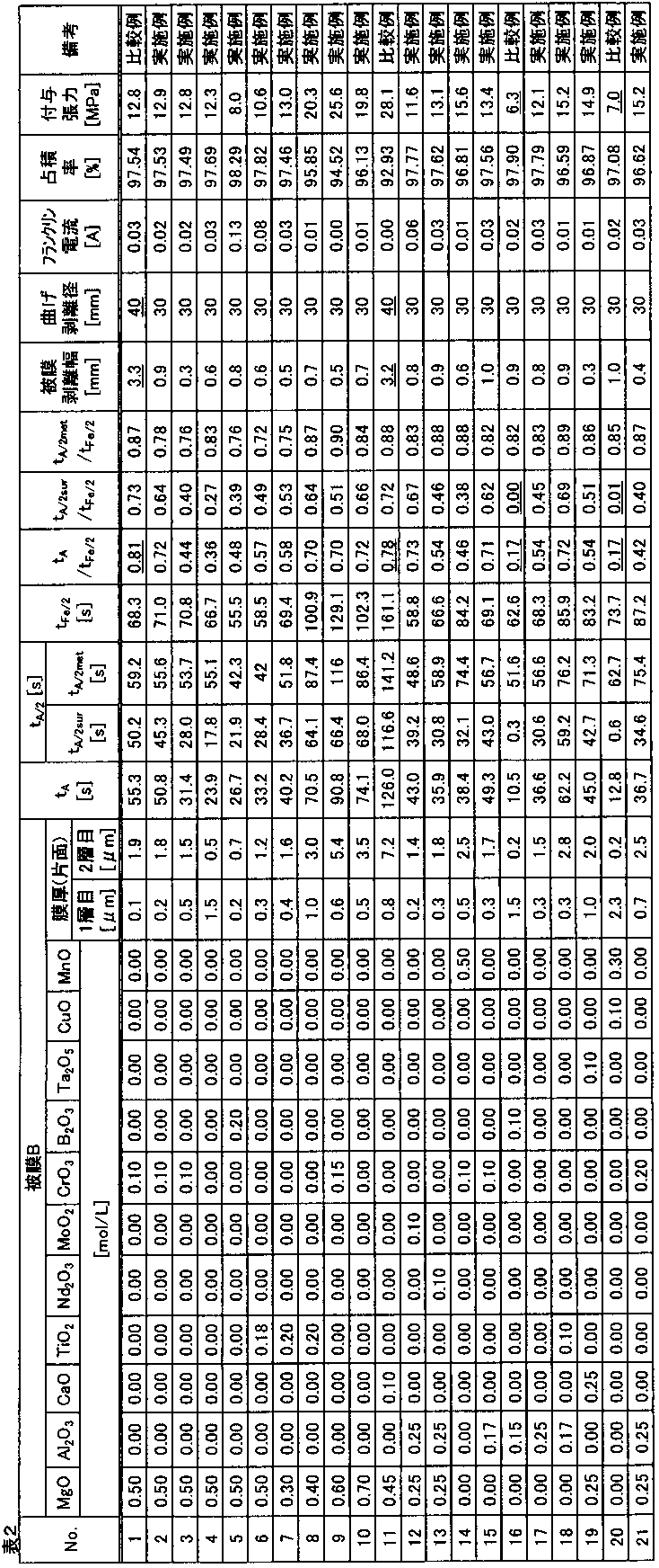
被膜Bに関して、膜厚が増加するにともなって、鋼板への付与張力がより高くなる傾向が見られた。
0.35≦(tA/tFe/2)および0.25≦(tA/2surtFe/2)を満たさないNo.16および20は、鋼板への付与張力が不十分であった。
〈方向性電磁鋼板の作製〉
以下に説明するようにして、鋼板上に被膜Aおよび被膜Bをこの順に有する方向性電磁鋼板の試料を作製した。
この珪素鋼スラブに、1100℃で30分間の加熱を施した後、熱間圧延を施して、2.2mmの板厚の熱延板を得た。得られた熱延板に、1000℃で1分間の焼鈍を施した後、冷間圧延を施して、0.23mmの最終板厚の冷延板とした。引き続き、冷延板を、室温から820℃まで加熱速度20℃/sで昇温させ、湿潤雰囲気下で820℃60秒間の一次再結晶焼鈍を施した。次いで、一次再結晶焼鈍を施した冷延板の表面に、MgO50質量部に対して150質量部のAl2O3と1質量部のNa2B4O7・10H2Oとを混合した焼鈍分離剤を、水スラリ状にしてから塗布し、乾燥した。乾燥後の冷延板を、300℃から800℃の間を100時間かけて昇温させた後、1200℃まで50℃/hrで昇温させ、1200℃で5時間焼鈍する最終仕上げ焼鈍を行なった。これにより、結晶質としてコーディエライト(2MgO・2Al2O3・5SiO2)を含む被膜A付きの鋼板(コイル)を得た。得られたコイルの中央部から、100mm(圧延直角方向)×400mm(圧延方向)のサイズの試料を採取した。
一部の試料においては、硫酸とフッ酸との混酸を用いて被膜A(コーディエライト被膜)を剥離し、PVD法を用いて、結晶質として下記表3に示す窒化物を含む被膜A(窒化物被膜)を形成した。
被膜Aの膜厚(単位:μm)は、下記表3に示す。
被膜Aにおける結晶質の含有量は、いずれも80質量%以上であった。
塗布および焼付は2回行ない、2層の被膜Bを形成した。1層目の被膜Bを形成する際には、ガラスフリットに0.2質量%のKOHを添加した。
被膜Bの焼付条件は、1層目および2層目ともに、1000℃で10分間、窒素雰囲気下とした。
被膜Bの膜厚(片面、単位:μm)は、下記表3に記載のとおりとした。膜厚は、断面SEM観察にて評価した。
作製した方向性電磁鋼板の試料について、試験例1と同様にして、Feのプロファイルの半価時間tFe/2、ならびに、アルカリ金属元素(K)のプロファイルのピーク時間tAおよび半価時間tA/2(tA/2sur、tA/2met)を求めた。更に、tA/tFe/2、tA/2sur/tFe/2、および、tA/2met/tFe/2を求めた。結果を下記表3に示す。
作製した方向性電磁鋼板の試料について、試験例1と同様にして、被膜剥離幅、曲げ剥離径および付与張力を求めた。更に、試験例2と同様にして、層間抵抗(フランクリン電流値)および占積率を求めた。結果を下記表3に示す。
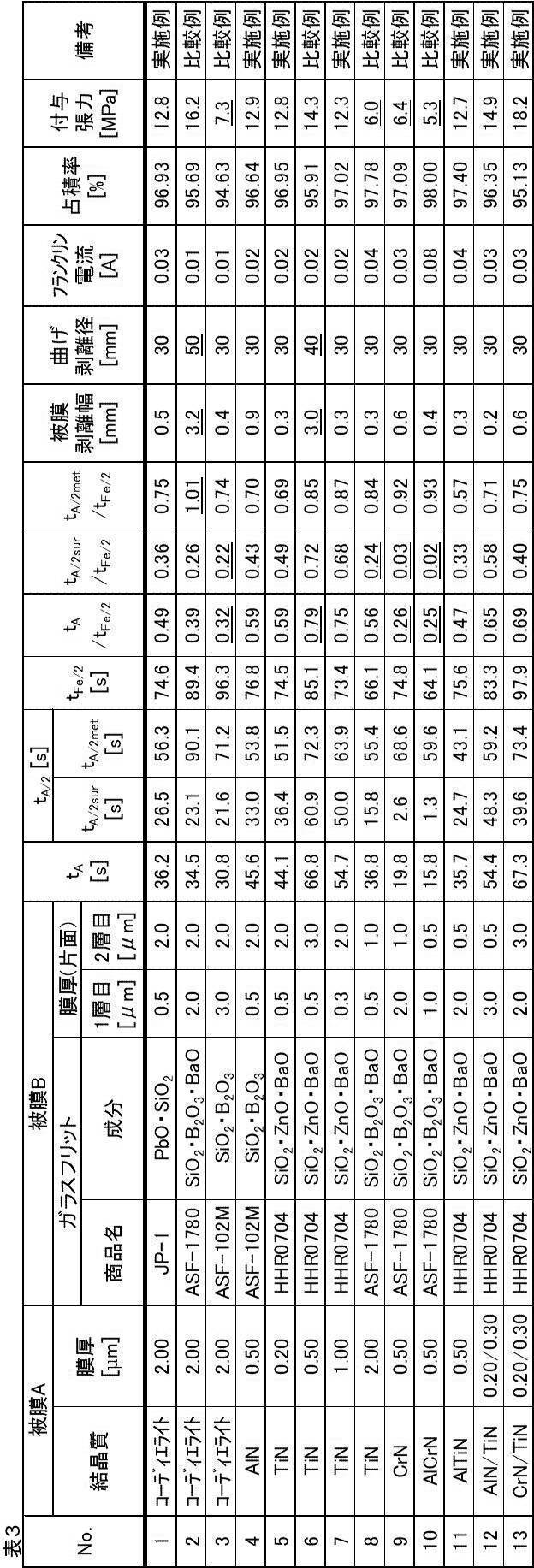
被膜Bに関して、膜厚が増加するにともなって、鋼板への付与張力がより高くなる傾向が見られた。
0.35≦(tA/tFe/2)および0.25≦(tA/2surtFe/2)の少なくともいずれかを満たさないNo.3、8、9および10は、鋼板への付与張力が不十分であった。
(tA/tFe/2)≦0.75を満たさないNo.6は、被膜剥離幅および曲げ剥離径が大きく被膜密着性が劣っていた。
Claims (10)
- 鋼板と、前記鋼板上に配置された結晶質を含む被膜Aと、前記被膜A上に配置されたガラス質を含む被膜Bと、を備える方向性電磁鋼板であって、
高周波グロー放電発光表面分析法を用いて得られる、前記被膜Bから前記鋼板に向かう方向の元素プロファイルが、下記式(1)および(2)を満たす、方向性電磁鋼板。
0.35≦(tA/tFe/2)≦0.75・・・(1)
0.25≦(tA/2/tFe/2)≦1.00・・・(2)
ただし、tAはアルカリ金属元素のプロファイルのピーク時間、tA/2はアルカリ金属元素のプロファイルの半価時間、tFe/2はFeのプロファイルの半価時間を示す。 - 前記被膜Aが含む前記結晶質が、酸化物である、請求項1に記載の方向性電磁鋼板。
- 前記酸化物が、フォルステライトおよびコーディエライトからなる群から選ばれる少なくとも1種である、請求項2に記載の方向性電磁鋼板。
- 前記被膜Aが含む前記結晶質が、窒化物である、請求項1に記載の方向性電磁鋼板。
- 前記窒化物が、窒化チタン、窒化アルミニウムおよび窒化クロムからなる群から選ばれる少なくとも1種である、請求項4に記載の方向性電磁鋼板。
- 前記被膜Bが含む前記ガラス質が、珪リン酸塩ガラスである、請求項1~5のいずれか1項に記載の方向性電磁鋼板。
- 前記珪リン酸塩ガラスが、Mg、Al、Ca、Ti、Nd、Mo、Cr、B、Ta、CuおよびMnからなる群から選ばれる少なくとも1種の金属元素を含む珪リン酸塩ガラスである、請求項6に記載の方向性電磁鋼板。
- 前記アルカリ金属元素が、NaおよびKからなる群から選ばれる少なくとも1種である、請求項1~7のいずれか1項に記載の方向性電磁鋼板。
- 請求項1~8のいずれか1項に記載の方向性電磁鋼板を製造する方法であって、
前記鋼板上に前記被膜Aが配置された被膜A付き鋼板を得る工程と、
前記被膜A付き鋼板の前記被膜A上に、前記被膜Bを形成する工程と、を備え、
前記被膜Bを形成する前に、前記被膜A付き鋼板を、アルカリ金属化合物の水溶液に浸漬し、その後、水洗し、乾燥し、
前記乾燥後の前記被膜A付き鋼板における、前記アルカリ金属化合物のアルカリ金属元素換算の目付量が、両面で、1.0×10⁻⁵mol/m2以上である、方向性電磁鋼板の製造方法。 - 前記目付量が、1.0×10⁻²mol/m2以下である、請求項9に記載の方向性電磁鋼板の製造方法。
Priority Applications (6)
| Application Number | Priority Date | Filing Date | Title |
|---|---|---|---|
| JP2018568983A JP6573042B1 (ja) | 2017-11-28 | 2018-10-12 | 方向性電磁鋼板およびその製造方法 |
| CN201880075675.9A CN111406126B (zh) | 2017-11-28 | 2018-10-12 | 取向性电磁钢板及其制造方法 |
| US16/766,090 US11473176B2 (en) | 2017-11-28 | 2018-10-12 | Oriented electrical steel sheet and method for producing same |
| KR1020207013522A KR102432967B1 (ko) | 2017-11-28 | 2018-10-12 | 방향성 전기 강판 및 그 제조 방법 |
| RU2020117184A RU2736247C1 (ru) | 2017-11-28 | 2018-10-12 | Текстурированная электротехническая листовая сталь и способ ее производства |
| EP18884687.7A EP3719169A4 (en) | 2017-11-28 | 2018-10-12 | ORIENTED ELECTRIC STEEL SHEET AND METHOD FOR MANUFACTURING THEREOF |
Applications Claiming Priority (2)
| Application Number | Priority Date | Filing Date | Title |
|---|---|---|---|
| JP2017228001 | 2017-11-28 | ||
| JP2017-228001 | 2017-11-28 |
Publications (1)
| Publication Number | Publication Date |
|---|---|
| WO2019106976A1 true WO2019106976A1 (ja) | 2019-06-06 |
Family
ID=66664825
Family Applications (1)
| Application Number | Title | Priority Date | Filing Date |
|---|---|---|---|
| PCT/JP2018/038133 Ceased WO2019106976A1 (ja) | 2017-11-28 | 2018-10-12 | 方向性電磁鋼板およびその製造方法 |
Country Status (7)
| Country | Link |
|---|---|
| US (1) | US11473176B2 (ja) |
| EP (1) | EP3719169A4 (ja) |
| JP (1) | JP6573042B1 (ja) |
| KR (1) | KR102432967B1 (ja) |
| CN (1) | CN111406126B (ja) |
| RU (1) | RU2736247C1 (ja) |
| WO (1) | WO2019106976A1 (ja) |
Cited By (4)
| Publication number | Priority date | Publication date | Assignee | Title |
|---|---|---|---|---|
| CN115135794A (zh) * | 2019-12-19 | 2022-09-30 | Posco公司 | 无取向电工钢板及其制造方法 |
| WO2023112421A1 (ja) * | 2021-12-14 | 2023-06-22 | Jfeスチール株式会社 | 方向性電磁鋼板およびその製造方法 |
| JPWO2024210186A1 (ja) * | 2023-04-05 | 2024-10-10 | ||
| WO2024210187A1 (ja) * | 2023-04-05 | 2024-10-10 | 日本製鉄株式会社 | 方向性電磁鋼板用絶縁被膜処理液およびその製造方法、ならびに方向性電磁鋼板の製造方法 |
Citations (7)
| Publication number | Priority date | Publication date | Assignee | Title |
|---|---|---|---|---|
| JPS4839338A (ja) | 1971-09-27 | 1973-06-09 | ||
| JPS5079442A (ja) | 1973-11-17 | 1975-06-27 | ||
| JPH0867913A (ja) | 1994-08-24 | 1996-03-12 | Nippon Steel Corp | 鉄損の小さい珪素鋼板及びその製造法及び使用法 |
| JPH08325745A (ja) * | 1995-05-26 | 1996-12-10 | Nippon Steel Corp | 低鉄損一方向性珪素鋼板およびその製造方法 |
| JPH1171683A (ja) | 1997-08-28 | 1999-03-16 | Nippon Steel Corp | 高張力絶縁被膜を有する方向性電磁鋼板とその処理方法 |
| JP2015147988A (ja) * | 2014-02-07 | 2015-08-20 | Jfeスチール株式会社 | 方向性電磁鋼板およびその製造方法 |
| JP2017122247A (ja) * | 2016-01-05 | 2017-07-13 | Jfeスチール株式会社 | 方向性電磁鋼板の製造方法 |
Family Cites Families (21)
| Publication number | Priority date | Publication date | Assignee | Title |
|---|---|---|---|---|
| GB1234181A (ja) * | 1967-06-14 | 1971-06-03 | ||
| EP0193324B1 (en) * | 1985-02-22 | 1989-10-11 | Kawasaki Steel Corporation | Extra-low iron loss grain oriented silicon steel sheets |
| CN1039915C (zh) | 1989-07-05 | 1998-09-23 | 新日本制铁株式会社 | 方向性电磁钢板上的绝缘皮膜成型方法 |
| JPH0483938A (ja) | 1990-07-26 | 1992-03-17 | Nobuaki Debari | 回転体のバランス調節機構 |
| JPH0579442A (ja) | 1991-09-19 | 1993-03-30 | Hitachi Ltd | 点火用配電器のロータヘツド |
| US5411808A (en) | 1992-02-13 | 1995-05-02 | Nippon Steel Corporation | Oriented electrical steel sheet having low core loss and method of manufacturing same |
| WO1998044517A1 (fr) * | 1997-04-03 | 1998-10-08 | Kawasaki Steel Corporation | Tole d'acier au silicium unidirectionnel a perte ultra-faible dans le fer |
| DE69913624T2 (de) * | 1998-09-18 | 2004-06-09 | Jfe Steel Corp. | Kornorientieres Siliziumstahlblech und Herstellungsverfahren dafür |
| JP4259037B2 (ja) | 2002-05-21 | 2009-04-30 | Jfeスチール株式会社 | 方向性電磁鋼板の製造方法 |
| JP4012483B2 (ja) * | 2003-04-15 | 2007-11-21 | 新日本製鐵株式会社 | 一方向性電磁鋼板の絶縁皮膜形成方法、および皮膜密着性に優れた絶縁皮膜を有する一方向性電磁鋼板 |
| TWI270578B (en) | 2004-11-10 | 2007-01-11 | Jfe Steel Corp | Grain oriented electromagnetic steel plate and method for producing the same |
| EP2096185B1 (en) | 2006-11-22 | 2014-08-13 | Nippon Steel & Sumitomo Metal Corporation | Unidirectionally grain oriented electromagnetic steel sheet having excellent film adhesion, and method for manufacturing the same |
| EP2799594B1 (en) * | 2011-12-28 | 2018-10-31 | JFE Steel Corporation | Directional electromagnetic steel sheet with coating, and method for producing same |
| JP6031951B2 (ja) * | 2012-11-09 | 2016-11-24 | Jfeスチール株式会社 | 方向性電磁鋼板およびその製造方法 |
| DE102013107506A1 (de) * | 2013-07-16 | 2015-01-22 | Thyssenkrupp Rasselstein Gmbh | Verfahren zur Passivierung von bandförmigem Schwarzblech |
| JP6156646B2 (ja) * | 2013-10-30 | 2017-07-05 | Jfeスチール株式会社 | 磁気特性および被膜密着性に優れる方向性電磁鋼板 |
| BR112017003450B1 (pt) | 2014-09-01 | 2021-06-22 | Nippon Steel Corporation | Chapa de aço elétrico com grão orientado e método de produção da referida chapa |
| JP6168173B2 (ja) * | 2015-01-30 | 2017-07-26 | Jfeスチール株式会社 | 方向性電磁鋼板とその製造方法 |
| KR101952237B1 (ko) * | 2015-02-05 | 2019-02-26 | 제이에프이 스틸 가부시키가이샤 | 방향성 전자 강판 및 그의 제조 방법 그리고 변압기 소음 특성의 예측 방법 |
| JP6547835B2 (ja) * | 2015-09-29 | 2019-07-24 | 日本製鉄株式会社 | 方向性電磁鋼板、及び方向性電磁鋼板の製造方法 |
| WO2018123339A1 (ja) * | 2016-12-28 | 2018-07-05 | Jfeスチール株式会社 | 方向性電磁鋼板、変圧器の鉄心および変圧器ならびに変圧器の騒音の低減方法 |
-
2018
- 2018-10-12 WO PCT/JP2018/038133 patent/WO2019106976A1/ja not_active Ceased
- 2018-10-12 JP JP2018568983A patent/JP6573042B1/ja active Active
- 2018-10-12 RU RU2020117184A patent/RU2736247C1/ru active
- 2018-10-12 US US16/766,090 patent/US11473176B2/en active Active
- 2018-10-12 KR KR1020207013522A patent/KR102432967B1/ko active Active
- 2018-10-12 CN CN201880075675.9A patent/CN111406126B/zh active Active
- 2018-10-12 EP EP18884687.7A patent/EP3719169A4/en active Pending
Patent Citations (7)
| Publication number | Priority date | Publication date | Assignee | Title |
|---|---|---|---|---|
| JPS4839338A (ja) | 1971-09-27 | 1973-06-09 | ||
| JPS5079442A (ja) | 1973-11-17 | 1975-06-27 | ||
| JPH0867913A (ja) | 1994-08-24 | 1996-03-12 | Nippon Steel Corp | 鉄損の小さい珪素鋼板及びその製造法及び使用法 |
| JPH08325745A (ja) * | 1995-05-26 | 1996-12-10 | Nippon Steel Corp | 低鉄損一方向性珪素鋼板およびその製造方法 |
| JPH1171683A (ja) | 1997-08-28 | 1999-03-16 | Nippon Steel Corp | 高張力絶縁被膜を有する方向性電磁鋼板とその処理方法 |
| JP2015147988A (ja) * | 2014-02-07 | 2015-08-20 | Jfeスチール株式会社 | 方向性電磁鋼板およびその製造方法 |
| JP2017122247A (ja) * | 2016-01-05 | 2017-07-13 | Jfeスチール株式会社 | 方向性電磁鋼板の製造方法 |
Non-Patent Citations (1)
| Title |
|---|
| See also references of EP3719169A4 |
Cited By (12)
| Publication number | Priority date | Publication date | Assignee | Title |
|---|---|---|---|---|
| CN115135794A (zh) * | 2019-12-19 | 2022-09-30 | Posco公司 | 无取向电工钢板及其制造方法 |
| CN115135794B (zh) * | 2019-12-19 | 2023-12-19 | Posco公司 | 无取向电工钢板及其制造方法 |
| WO2023112421A1 (ja) * | 2021-12-14 | 2023-06-22 | Jfeスチール株式会社 | 方向性電磁鋼板およびその製造方法 |
| JPWO2023112421A1 (ja) * | 2021-12-14 | 2023-06-22 | ||
| JP7529055B2 (ja) | 2021-12-14 | 2024-08-06 | Jfeスチール株式会社 | 方向性電磁鋼板およびその製造方法 |
| EP4417717A4 (en) * | 2021-12-14 | 2025-04-23 | JFE Steel Corporation | GRAIN-ORIENTED ELECTROMAGNETIC STEEL SHEET AND METHOD FOR PRODUCING THE SAME |
| JPWO2024210186A1 (ja) * | 2023-04-05 | 2024-10-10 | ||
| WO2024210186A1 (ja) * | 2023-04-05 | 2024-10-10 | 日本製鉄株式会社 | 方向性電磁鋼板用絶縁被膜処理液および方向性電磁鋼板の製造方法 |
| WO2024210187A1 (ja) * | 2023-04-05 | 2024-10-10 | 日本製鉄株式会社 | 方向性電磁鋼板用絶縁被膜処理液およびその製造方法、ならびに方向性電磁鋼板の製造方法 |
| JPWO2024210187A1 (ja) * | 2023-04-05 | 2024-10-10 | ||
| JP7810936B2 (ja) | 2023-04-05 | 2026-02-04 | 日本製鉄株式会社 | 方向性電磁鋼板用絶縁被膜処理液および方向性電磁鋼板の製造方法 |
| JP7810937B2 (ja) | 2023-04-05 | 2026-02-04 | 日本製鉄株式会社 | 方向性電磁鋼板用絶縁被膜処理液およびその製造方法、ならびに方向性電磁鋼板の製造方法 |
Also Published As
| Publication number | Publication date |
|---|---|
| JP6573042B1 (ja) | 2019-09-11 |
| US20200354821A1 (en) | 2020-11-12 |
| CN111406126B (zh) | 2022-04-29 |
| CN111406126A (zh) | 2020-07-10 |
| EP3719169A1 (en) | 2020-10-07 |
| KR20200069342A (ko) | 2020-06-16 |
| RU2736247C1 (ru) | 2020-11-12 |
| JPWO2019106976A1 (ja) | 2019-12-12 |
| EP3719169A4 (en) | 2021-01-13 |
| US11473176B2 (en) | 2022-10-18 |
| KR102432967B1 (ko) | 2022-08-16 |
Similar Documents
| Publication | Publication Date | Title |
|---|---|---|
| JP5181571B2 (ja) | 方向性電磁鋼板用クロムフリー絶縁被膜処理液および絶縁被膜付方向性電磁鋼板の製造方法 | |
| KR101763085B1 (ko) | 자기 특성 및 피막 밀착성이 우수한 방향성 전기 강판 | |
| JP6332453B2 (ja) | 絶縁被膜付き方向性電磁鋼板およびその製造方法 | |
| JP2009052060A (ja) | 方向性電磁鋼板用絶縁被膜処理液および絶縁被膜付方向性電磁鋼板の製造方法 | |
| JP6031951B2 (ja) | 方向性電磁鋼板およびその製造方法 | |
| JP6573042B1 (ja) | 方向性電磁鋼板およびその製造方法 | |
| JP6558325B2 (ja) | クロムフリー張力被膜形成用処理液、クロムフリー張力被膜付方向性電磁鋼板、クロムフリー張力被膜付方向性電磁鋼板の製造方法およびトランス用コア | |
| WO2020149351A1 (ja) | 方向性電磁鋼板の製造方法 | |
| JP5272469B2 (ja) | 方向性電磁鋼板およびその製造方法 | |
| JP5262228B2 (ja) | 方向性電磁鋼板およびその製造方法 | |
| WO2019155858A1 (ja) | 絶縁被膜付き電磁鋼板およびその製造方法 | |
| JP2008240080A (ja) | 方向性電磁鋼板用絶縁被膜処理液および方向性電磁鋼板の製造方法 | |
| JP6332452B2 (ja) | 絶縁被膜付き方向性電磁鋼板およびその製造方法 | |
| JP4635457B2 (ja) | クロムを含まず耐吸湿性に優れたリン酸塩系絶縁被膜を有する方向性電磁鋼板およびクロムを含まず耐吸湿性に優れたリン酸塩系絶縁被膜の被成方法。 | |
| JP2003171773A (ja) | 張力皮膜を有する一方向性珪素鋼板 | |
| JP7222450B1 (ja) | 前処理液および絶縁被膜付き電磁鋼板の製造方法 | |
| JP7311075B1 (ja) | 前処理液および絶縁被膜付き電磁鋼板の製造方法 | |
| CN114106593B (zh) | 一种用于取向硅钢表面涂层的涂料、取向硅钢板及其制造方法 | |
| JP7810937B2 (ja) | 方向性電磁鋼板用絶縁被膜処理液およびその製造方法、ならびに方向性電磁鋼板の製造方法 | |
| JP7855739B2 (ja) | コーティング材料、コーティング材料から形成されたコーティングを有する方向性ケイ素鋼板およびその製造方法 | |
| WO2020149327A1 (ja) | 方向性電磁鋼板の製造方法 | |
| JP7473859B1 (ja) | 絶縁被膜付き電磁鋼板の製造方法 | |
| JP7810936B2 (ja) | 方向性電磁鋼板用絶縁被膜処理液および方向性電磁鋼板の製造方法 | |
| JP2003034880A (ja) | 方向性電磁鋼板の表面上に密着性に優れた絶縁被膜を形成する方法および方向性電磁鋼板の製造方法 | |
| WO2020149323A1 (ja) | 方向性電磁鋼板の製造方法 |
Legal Events
| Date | Code | Title | Description |
|---|---|---|---|
| ENP | Entry into the national phase |
Ref document number: 2018568983 Country of ref document: JP Kind code of ref document: A |
|
| 121 | Ep: the epo has been informed by wipo that ep was designated in this application |
Ref document number: 18884687 Country of ref document: EP Kind code of ref document: A1 |
|
| ENP | Entry into the national phase |
Ref document number: 20207013522 Country of ref document: KR Kind code of ref document: A |
|
| NENP | Non-entry into the national phase |
Ref country code: DE |
|
| ENP | Entry into the national phase |
Ref document number: 2018884687 Country of ref document: EP Effective date: 20200629 |