WO2019106976A1 - Tôle magnétique en acier à grains orientés et son procédé de production - Google Patents
Tôle magnétique en acier à grains orientés et son procédé de production Download PDFInfo
- Publication number
- WO2019106976A1 WO2019106976A1 PCT/JP2018/038133 JP2018038133W WO2019106976A1 WO 2019106976 A1 WO2019106976 A1 WO 2019106976A1 JP 2018038133 W JP2018038133 W JP 2018038133W WO 2019106976 A1 WO2019106976 A1 WO 2019106976A1
- Authority
- WO
- WIPO (PCT)
- Prior art keywords
- film
- steel sheet
- coating
- alkali metal
- electrical steel
- Prior art date
- Legal status (The legal status is an assumption and is not a legal conclusion. Google has not performed a legal analysis and makes no representation as to the accuracy of the status listed.)
- Ceased
Links
Images
Classifications
-
- C—CHEMISTRY; METALLURGY
- C23—COATING METALLIC MATERIAL; COATING MATERIAL WITH METALLIC MATERIAL; CHEMICAL SURFACE TREATMENT; DIFFUSION TREATMENT OF METALLIC MATERIAL; COATING BY VACUUM EVAPORATION, BY SPUTTERING, BY ION IMPLANTATION OR BY CHEMICAL VAPOUR DEPOSITION, IN GENERAL; INHIBITING CORROSION OF METALLIC MATERIAL OR INCRUSTATION IN GENERAL
- C23C—COATING METALLIC MATERIAL; COATING MATERIAL WITH METALLIC MATERIAL; SURFACE TREATMENT OF METALLIC MATERIAL BY DIFFUSION INTO THE SURFACE, BY CHEMICAL CONVERSION OR SUBSTITUTION; COATING BY VACUUM EVAPORATION, BY SPUTTERING, BY ION IMPLANTATION OR BY CHEMICAL VAPOUR DEPOSITION, IN GENERAL
- C23C28/00—Coating for obtaining at least two superposed coatings either by methods not provided for in a single one of groups C23C2/00 - C23C26/00 or by combinations of methods provided for in subclasses C23C and C25C or C25D
- C23C28/04—Coating for obtaining at least two superposed coatings either by methods not provided for in a single one of groups C23C2/00 - C23C26/00 or by combinations of methods provided for in subclasses C23C and C25C or C25D only coatings of inorganic non-metallic material
- C23C28/042—Coating for obtaining at least two superposed coatings either by methods not provided for in a single one of groups C23C2/00 - C23C26/00 or by combinations of methods provided for in subclasses C23C and C25C or C25D only coatings of inorganic non-metallic material including a refractory ceramic layer, e.g. refractory metal oxides, ZrO2, rare earth oxides
-
- B—PERFORMING OPERATIONS; TRANSPORTING
- B32—LAYERED PRODUCTS
- B32B—LAYERED PRODUCTS, i.e. PRODUCTS BUILT-UP OF STRATA OF FLAT OR NON-FLAT, e.g. CELLULAR OR HONEYCOMB, FORM
- B32B15/00—Layered products comprising a layer of metal
- B32B15/04—Layered products comprising a layer of metal comprising metal as the main or only constituent of a layer, which is next to another layer of the same or of a different material
-
- C—CHEMISTRY; METALLURGY
- C21—METALLURGY OF IRON
- C21D—MODIFYING THE PHYSICAL STRUCTURE OF FERROUS METALS; GENERAL DEVICES FOR HEAT TREATMENT OF FERROUS OR NON-FERROUS METALS OR ALLOYS; MAKING METAL MALLEABLE, e.g. BY DECARBURISATION OR TEMPERING
- C21D8/00—Modifying the physical properties of ferrous metals or ferrous alloys by deformation combined with, or followed by, heat treatment
- C21D8/02—Modifying the physical properties of ferrous metals or ferrous alloys by deformation combined with, or followed by, heat treatment during manufacturing of plates or strips
- C21D8/0221—Modifying the physical properties of ferrous metals or ferrous alloys by deformation combined with, or followed by, heat treatment during manufacturing of plates or strips characterised by the working steps
- C21D8/0226—Hot rolling
-
- C—CHEMISTRY; METALLURGY
- C21—METALLURGY OF IRON
- C21D—MODIFYING THE PHYSICAL STRUCTURE OF FERROUS METALS; GENERAL DEVICES FOR HEAT TREATMENT OF FERROUS OR NON-FERROUS METALS OR ALLOYS; MAKING METAL MALLEABLE, e.g. BY DECARBURISATION OR TEMPERING
- C21D8/00—Modifying the physical properties of ferrous metals or ferrous alloys by deformation combined with, or followed by, heat treatment
- C21D8/02—Modifying the physical properties of ferrous metals or ferrous alloys by deformation combined with, or followed by, heat treatment during manufacturing of plates or strips
- C21D8/0221—Modifying the physical properties of ferrous metals or ferrous alloys by deformation combined with, or followed by, heat treatment during manufacturing of plates or strips characterised by the working steps
- C21D8/0236—Cold rolling
-
- C—CHEMISTRY; METALLURGY
- C21—METALLURGY OF IRON
- C21D—MODIFYING THE PHYSICAL STRUCTURE OF FERROUS METALS; GENERAL DEVICES FOR HEAT TREATMENT OF FERROUS OR NON-FERROUS METALS OR ALLOYS; MAKING METAL MALLEABLE, e.g. BY DECARBURISATION OR TEMPERING
- C21D8/00—Modifying the physical properties of ferrous metals or ferrous alloys by deformation combined with, or followed by, heat treatment
- C21D8/12—Modifying the physical properties of ferrous metals or ferrous alloys by deformation combined with, or followed by, heat treatment during manufacturing of articles with special electromagnetic properties
- C21D8/1277—Modifying the physical properties of ferrous metals or ferrous alloys by deformation combined with, or followed by, heat treatment during manufacturing of articles with special electromagnetic properties involving a particular surface treatment
-
- C—CHEMISTRY; METALLURGY
- C21—METALLURGY OF IRON
- C21D—MODIFYING THE PHYSICAL STRUCTURE OF FERROUS METALS; GENERAL DEVICES FOR HEAT TREATMENT OF FERROUS OR NON-FERROUS METALS OR ALLOYS; MAKING METAL MALLEABLE, e.g. BY DECARBURISATION OR TEMPERING
- C21D9/00—Heat treatment, e.g. annealing, hardening, quenching or tempering, adapted for particular articles; Furnaces therefor
- C21D9/46—Heat treatment, e.g. annealing, hardening, quenching or tempering, adapted for particular articles; Furnaces therefor for sheet metals
-
- C—CHEMISTRY; METALLURGY
- C22—METALLURGY; FERROUS OR NON-FERROUS ALLOYS; TREATMENT OF ALLOYS OR NON-FERROUS METALS
- C22C—ALLOYS
- C22C38/00—Ferrous alloys, e.g. steel alloys
-
- C—CHEMISTRY; METALLURGY
- C22—METALLURGY; FERROUS OR NON-FERROUS ALLOYS; TREATMENT OF ALLOYS OR NON-FERROUS METALS
- C22C—ALLOYS
- C22C38/00—Ferrous alloys, e.g. steel alloys
- C22C38/02—Ferrous alloys, e.g. steel alloys containing silicon
-
- C—CHEMISTRY; METALLURGY
- C22—METALLURGY; FERROUS OR NON-FERROUS ALLOYS; TREATMENT OF ALLOYS OR NON-FERROUS METALS
- C22C—ALLOYS
- C22C38/00—Ferrous alloys, e.g. steel alloys
- C22C38/04—Ferrous alloys, e.g. steel alloys containing manganese
-
- C—CHEMISTRY; METALLURGY
- C22—METALLURGY; FERROUS OR NON-FERROUS ALLOYS; TREATMENT OF ALLOYS OR NON-FERROUS METALS
- C22C—ALLOYS
- C22C38/00—Ferrous alloys, e.g. steel alloys
- C22C38/06—Ferrous alloys, e.g. steel alloys containing aluminium
-
- C—CHEMISTRY; METALLURGY
- C22—METALLURGY; FERROUS OR NON-FERROUS ALLOYS; TREATMENT OF ALLOYS OR NON-FERROUS METALS
- C22C—ALLOYS
- C22C38/00—Ferrous alloys, e.g. steel alloys
- C22C38/60—Ferrous alloys, e.g. steel alloys containing lead, selenium, tellurium, or antimony, or more than 0.04% by weight of sulfur
-
- C—CHEMISTRY; METALLURGY
- C23—COATING METALLIC MATERIAL; COATING MATERIAL WITH METALLIC MATERIAL; CHEMICAL SURFACE TREATMENT; DIFFUSION TREATMENT OF METALLIC MATERIAL; COATING BY VACUUM EVAPORATION, BY SPUTTERING, BY ION IMPLANTATION OR BY CHEMICAL VAPOUR DEPOSITION, IN GENERAL; INHIBITING CORROSION OF METALLIC MATERIAL OR INCRUSTATION IN GENERAL
- C23C—COATING METALLIC MATERIAL; COATING MATERIAL WITH METALLIC MATERIAL; SURFACE TREATMENT OF METALLIC MATERIAL BY DIFFUSION INTO THE SURFACE, BY CHEMICAL CONVERSION OR SUBSTITUTION; COATING BY VACUUM EVAPORATION, BY SPUTTERING, BY ION IMPLANTATION OR BY CHEMICAL VAPOUR DEPOSITION, IN GENERAL
- C23C14/00—Coating by vacuum evaporation, by sputtering or by ion implantation of the coating forming material
- C23C14/06—Coating by vacuum evaporation, by sputtering or by ion implantation of the coating forming material characterised by the coating material
- C23C14/0641—Nitrides
-
- C—CHEMISTRY; METALLURGY
- C23—COATING METALLIC MATERIAL; COATING MATERIAL WITH METALLIC MATERIAL; CHEMICAL SURFACE TREATMENT; DIFFUSION TREATMENT OF METALLIC MATERIAL; COATING BY VACUUM EVAPORATION, BY SPUTTERING, BY ION IMPLANTATION OR BY CHEMICAL VAPOUR DEPOSITION, IN GENERAL; INHIBITING CORROSION OF METALLIC MATERIAL OR INCRUSTATION IN GENERAL
- C23C—COATING METALLIC MATERIAL; COATING MATERIAL WITH METALLIC MATERIAL; SURFACE TREATMENT OF METALLIC MATERIAL BY DIFFUSION INTO THE SURFACE, BY CHEMICAL CONVERSION OR SUBSTITUTION; COATING BY VACUUM EVAPORATION, BY SPUTTERING, BY ION IMPLANTATION OR BY CHEMICAL VAPOUR DEPOSITION, IN GENERAL
- C23C14/00—Coating by vacuum evaporation, by sputtering or by ion implantation of the coating forming material
- C23C14/06—Coating by vacuum evaporation, by sputtering or by ion implantation of the coating forming material characterised by the coating material
- C23C14/08—Oxides
-
- C—CHEMISTRY; METALLURGY
- C23—COATING METALLIC MATERIAL; COATING MATERIAL WITH METALLIC MATERIAL; CHEMICAL SURFACE TREATMENT; DIFFUSION TREATMENT OF METALLIC MATERIAL; COATING BY VACUUM EVAPORATION, BY SPUTTERING, BY ION IMPLANTATION OR BY CHEMICAL VAPOUR DEPOSITION, IN GENERAL; INHIBITING CORROSION OF METALLIC MATERIAL OR INCRUSTATION IN GENERAL
- C23C—COATING METALLIC MATERIAL; COATING MATERIAL WITH METALLIC MATERIAL; SURFACE TREATMENT OF METALLIC MATERIAL BY DIFFUSION INTO THE SURFACE, BY CHEMICAL CONVERSION OR SUBSTITUTION; COATING BY VACUUM EVAPORATION, BY SPUTTERING, BY ION IMPLANTATION OR BY CHEMICAL VAPOUR DEPOSITION, IN GENERAL
- C23C14/00—Coating by vacuum evaporation, by sputtering or by ion implantation of the coating forming material
- C23C14/06—Coating by vacuum evaporation, by sputtering or by ion implantation of the coating forming material characterised by the coating material
- C23C14/10—Glass or silica
-
- C—CHEMISTRY; METALLURGY
- C23—COATING METALLIC MATERIAL; COATING MATERIAL WITH METALLIC MATERIAL; CHEMICAL SURFACE TREATMENT; DIFFUSION TREATMENT OF METALLIC MATERIAL; COATING BY VACUUM EVAPORATION, BY SPUTTERING, BY ION IMPLANTATION OR BY CHEMICAL VAPOUR DEPOSITION, IN GENERAL; INHIBITING CORROSION OF METALLIC MATERIAL OR INCRUSTATION IN GENERAL
- C23C—COATING METALLIC MATERIAL; COATING MATERIAL WITH METALLIC MATERIAL; SURFACE TREATMENT OF METALLIC MATERIAL BY DIFFUSION INTO THE SURFACE, BY CHEMICAL CONVERSION OR SUBSTITUTION; COATING BY VACUUM EVAPORATION, BY SPUTTERING, BY ION IMPLANTATION OR BY CHEMICAL VAPOUR DEPOSITION, IN GENERAL
- C23C14/00—Coating by vacuum evaporation, by sputtering or by ion implantation of the coating forming material
- C23C14/06—Coating by vacuum evaporation, by sputtering or by ion implantation of the coating forming material characterised by the coating material
- C23C14/14—Metallic material, boron or silicon
- C23C14/16—Metallic material, boron or silicon on metallic substrates or on substrates of boron or silicon
-
- C—CHEMISTRY; METALLURGY
- C23—COATING METALLIC MATERIAL; COATING MATERIAL WITH METALLIC MATERIAL; CHEMICAL SURFACE TREATMENT; DIFFUSION TREATMENT OF METALLIC MATERIAL; COATING BY VACUUM EVAPORATION, BY SPUTTERING, BY ION IMPLANTATION OR BY CHEMICAL VAPOUR DEPOSITION, IN GENERAL; INHIBITING CORROSION OF METALLIC MATERIAL OR INCRUSTATION IN GENERAL
- C23C—COATING METALLIC MATERIAL; COATING MATERIAL WITH METALLIC MATERIAL; SURFACE TREATMENT OF METALLIC MATERIAL BY DIFFUSION INTO THE SURFACE, BY CHEMICAL CONVERSION OR SUBSTITUTION; COATING BY VACUUM EVAPORATION, BY SPUTTERING, BY ION IMPLANTATION OR BY CHEMICAL VAPOUR DEPOSITION, IN GENERAL
- C23C14/00—Coating by vacuum evaporation, by sputtering or by ion implantation of the coating forming material
- C23C14/22—Coating by vacuum evaporation, by sputtering or by ion implantation of the coating forming material characterised by the process of coating
- C23C14/34—Sputtering
-
- C—CHEMISTRY; METALLURGY
- C23—COATING METALLIC MATERIAL; COATING MATERIAL WITH METALLIC MATERIAL; CHEMICAL SURFACE TREATMENT; DIFFUSION TREATMENT OF METALLIC MATERIAL; COATING BY VACUUM EVAPORATION, BY SPUTTERING, BY ION IMPLANTATION OR BY CHEMICAL VAPOUR DEPOSITION, IN GENERAL; INHIBITING CORROSION OF METALLIC MATERIAL OR INCRUSTATION IN GENERAL
- C23C—COATING METALLIC MATERIAL; COATING MATERIAL WITH METALLIC MATERIAL; SURFACE TREATMENT OF METALLIC MATERIAL BY DIFFUSION INTO THE SURFACE, BY CHEMICAL CONVERSION OR SUBSTITUTION; COATING BY VACUUM EVAPORATION, BY SPUTTERING, BY ION IMPLANTATION OR BY CHEMICAL VAPOUR DEPOSITION, IN GENERAL
- C23C16/00—Chemical coating by decomposition of gaseous compounds, without leaving reaction products of surface material in the coating, i.e. chemical vapour deposition [CVD] processes
- C23C16/22—Chemical coating by decomposition of gaseous compounds, without leaving reaction products of surface material in the coating, i.e. chemical vapour deposition [CVD] processes characterised by the deposition of inorganic material, other than metallic material
- C23C16/30—Deposition of compounds, mixtures or solid solutions, e.g. borides, carbides, nitrides
- C23C16/301—AIII BV compounds, where A is Al, Ga, In or Tl and B is N, P, As, Sb or Bi
- C23C16/303—Nitrides
-
- C—CHEMISTRY; METALLURGY
- C23—COATING METALLIC MATERIAL; COATING MATERIAL WITH METALLIC MATERIAL; CHEMICAL SURFACE TREATMENT; DIFFUSION TREATMENT OF METALLIC MATERIAL; COATING BY VACUUM EVAPORATION, BY SPUTTERING, BY ION IMPLANTATION OR BY CHEMICAL VAPOUR DEPOSITION, IN GENERAL; INHIBITING CORROSION OF METALLIC MATERIAL OR INCRUSTATION IN GENERAL
- C23C—COATING METALLIC MATERIAL; COATING MATERIAL WITH METALLIC MATERIAL; SURFACE TREATMENT OF METALLIC MATERIAL BY DIFFUSION INTO THE SURFACE, BY CHEMICAL CONVERSION OR SUBSTITUTION; COATING BY VACUUM EVAPORATION, BY SPUTTERING, BY ION IMPLANTATION OR BY CHEMICAL VAPOUR DEPOSITION, IN GENERAL
- C23C16/00—Chemical coating by decomposition of gaseous compounds, without leaving reaction products of surface material in the coating, i.e. chemical vapour deposition [CVD] processes
- C23C16/22—Chemical coating by decomposition of gaseous compounds, without leaving reaction products of surface material in the coating, i.e. chemical vapour deposition [CVD] processes characterised by the deposition of inorganic material, other than metallic material
- C23C16/30—Deposition of compounds, mixtures or solid solutions, e.g. borides, carbides, nitrides
- C23C16/40—Oxides
-
- C—CHEMISTRY; METALLURGY
- C23—COATING METALLIC MATERIAL; COATING MATERIAL WITH METALLIC MATERIAL; CHEMICAL SURFACE TREATMENT; DIFFUSION TREATMENT OF METALLIC MATERIAL; COATING BY VACUUM EVAPORATION, BY SPUTTERING, BY ION IMPLANTATION OR BY CHEMICAL VAPOUR DEPOSITION, IN GENERAL; INHIBITING CORROSION OF METALLIC MATERIAL OR INCRUSTATION IN GENERAL
- C23C—COATING METALLIC MATERIAL; COATING MATERIAL WITH METALLIC MATERIAL; SURFACE TREATMENT OF METALLIC MATERIAL BY DIFFUSION INTO THE SURFACE, BY CHEMICAL CONVERSION OR SUBSTITUTION; COATING BY VACUUM EVAPORATION, BY SPUTTERING, BY ION IMPLANTATION OR BY CHEMICAL VAPOUR DEPOSITION, IN GENERAL
- C23C22/00—Chemical surface treatment of metallic material by reaction of the surface with a reactive liquid, leaving reaction products of surface material in the coating, e.g. conversion coatings, passivation of metals
- C23C22/05—Chemical surface treatment of metallic material by reaction of the surface with a reactive liquid, leaving reaction products of surface material in the coating, e.g. conversion coatings, passivation of metals using aqueous solutions
- C23C22/06—Chemical surface treatment of metallic material by reaction of the surface with a reactive liquid, leaving reaction products of surface material in the coating, e.g. conversion coatings, passivation of metals using aqueous solutions using aqueous acidic solutions with pH less than 6
- C23C22/07—Chemical surface treatment of metallic material by reaction of the surface with a reactive liquid, leaving reaction products of surface material in the coating, e.g. conversion coatings, passivation of metals using aqueous solutions using aqueous acidic solutions with pH less than 6 containing phosphates
- C23C22/08—Orthophosphates
-
- C—CHEMISTRY; METALLURGY
- C23—COATING METALLIC MATERIAL; COATING MATERIAL WITH METALLIC MATERIAL; CHEMICAL SURFACE TREATMENT; DIFFUSION TREATMENT OF METALLIC MATERIAL; COATING BY VACUUM EVAPORATION, BY SPUTTERING, BY ION IMPLANTATION OR BY CHEMICAL VAPOUR DEPOSITION, IN GENERAL; INHIBITING CORROSION OF METALLIC MATERIAL OR INCRUSTATION IN GENERAL
- C23C—COATING METALLIC MATERIAL; COATING MATERIAL WITH METALLIC MATERIAL; SURFACE TREATMENT OF METALLIC MATERIAL BY DIFFUSION INTO THE SURFACE, BY CHEMICAL CONVERSION OR SUBSTITUTION; COATING BY VACUUM EVAPORATION, BY SPUTTERING, BY ION IMPLANTATION OR BY CHEMICAL VAPOUR DEPOSITION, IN GENERAL
- C23C22/00—Chemical surface treatment of metallic material by reaction of the surface with a reactive liquid, leaving reaction products of surface material in the coating, e.g. conversion coatings, passivation of metals
- C23C22/05—Chemical surface treatment of metallic material by reaction of the surface with a reactive liquid, leaving reaction products of surface material in the coating, e.g. conversion coatings, passivation of metals using aqueous solutions
- C23C22/06—Chemical surface treatment of metallic material by reaction of the surface with a reactive liquid, leaving reaction products of surface material in the coating, e.g. conversion coatings, passivation of metals using aqueous solutions using aqueous acidic solutions with pH less than 6
- C23C22/24—Chemical surface treatment of metallic material by reaction of the surface with a reactive liquid, leaving reaction products of surface material in the coating, e.g. conversion coatings, passivation of metals using aqueous solutions using aqueous acidic solutions with pH less than 6 containing hexavalent chromium compounds
- C23C22/33—Chemical surface treatment of metallic material by reaction of the surface with a reactive liquid, leaving reaction products of surface material in the coating, e.g. conversion coatings, passivation of metals using aqueous solutions using aqueous acidic solutions with pH less than 6 containing hexavalent chromium compounds containing also phosphates
-
- C—CHEMISTRY; METALLURGY
- C23—COATING METALLIC MATERIAL; COATING MATERIAL WITH METALLIC MATERIAL; CHEMICAL SURFACE TREATMENT; DIFFUSION TREATMENT OF METALLIC MATERIAL; COATING BY VACUUM EVAPORATION, BY SPUTTERING, BY ION IMPLANTATION OR BY CHEMICAL VAPOUR DEPOSITION, IN GENERAL; INHIBITING CORROSION OF METALLIC MATERIAL OR INCRUSTATION IN GENERAL
- C23C—COATING METALLIC MATERIAL; COATING MATERIAL WITH METALLIC MATERIAL; SURFACE TREATMENT OF METALLIC MATERIAL BY DIFFUSION INTO THE SURFACE, BY CHEMICAL CONVERSION OR SUBSTITUTION; COATING BY VACUUM EVAPORATION, BY SPUTTERING, BY ION IMPLANTATION OR BY CHEMICAL VAPOUR DEPOSITION, IN GENERAL
- C23C22/00—Chemical surface treatment of metallic material by reaction of the surface with a reactive liquid, leaving reaction products of surface material in the coating, e.g. conversion coatings, passivation of metals
- C23C22/73—Chemical surface treatment of metallic material by reaction of the surface with a reactive liquid, leaving reaction products of surface material in the coating, e.g. conversion coatings, passivation of metals characterised by the process
- C23C22/74—Chemical surface treatment of metallic material by reaction of the surface with a reactive liquid, leaving reaction products of surface material in the coating, e.g. conversion coatings, passivation of metals characterised by the process for obtaining burned-in conversion coatings
-
- C—CHEMISTRY; METALLURGY
- C23—COATING METALLIC MATERIAL; COATING MATERIAL WITH METALLIC MATERIAL; CHEMICAL SURFACE TREATMENT; DIFFUSION TREATMENT OF METALLIC MATERIAL; COATING BY VACUUM EVAPORATION, BY SPUTTERING, BY ION IMPLANTATION OR BY CHEMICAL VAPOUR DEPOSITION, IN GENERAL; INHIBITING CORROSION OF METALLIC MATERIAL OR INCRUSTATION IN GENERAL
- C23C—COATING METALLIC MATERIAL; COATING MATERIAL WITH METALLIC MATERIAL; SURFACE TREATMENT OF METALLIC MATERIAL BY DIFFUSION INTO THE SURFACE, BY CHEMICAL CONVERSION OR SUBSTITUTION; COATING BY VACUUM EVAPORATION, BY SPUTTERING, BY ION IMPLANTATION OR BY CHEMICAL VAPOUR DEPOSITION, IN GENERAL
- C23C22/00—Chemical surface treatment of metallic material by reaction of the surface with a reactive liquid, leaving reaction products of surface material in the coating, e.g. conversion coatings, passivation of metals
- C23C22/78—Pretreatment of the material to be coated
-
- C—CHEMISTRY; METALLURGY
- C23—COATING METALLIC MATERIAL; COATING MATERIAL WITH METALLIC MATERIAL; CHEMICAL SURFACE TREATMENT; DIFFUSION TREATMENT OF METALLIC MATERIAL; COATING BY VACUUM EVAPORATION, BY SPUTTERING, BY ION IMPLANTATION OR BY CHEMICAL VAPOUR DEPOSITION, IN GENERAL; INHIBITING CORROSION OF METALLIC MATERIAL OR INCRUSTATION IN GENERAL
- C23C—COATING METALLIC MATERIAL; COATING MATERIAL WITH METALLIC MATERIAL; SURFACE TREATMENT OF METALLIC MATERIAL BY DIFFUSION INTO THE SURFACE, BY CHEMICAL CONVERSION OR SUBSTITUTION; COATING BY VACUUM EVAPORATION, BY SPUTTERING, BY ION IMPLANTATION OR BY CHEMICAL VAPOUR DEPOSITION, IN GENERAL
- C23C22/00—Chemical surface treatment of metallic material by reaction of the surface with a reactive liquid, leaving reaction products of surface material in the coating, e.g. conversion coatings, passivation of metals
- C23C22/82—After-treatment
- C23C22/83—Chemical after-treatment
-
- C—CHEMISTRY; METALLURGY
- C23—COATING METALLIC MATERIAL; COATING MATERIAL WITH METALLIC MATERIAL; CHEMICAL SURFACE TREATMENT; DIFFUSION TREATMENT OF METALLIC MATERIAL; COATING BY VACUUM EVAPORATION, BY SPUTTERING, BY ION IMPLANTATION OR BY CHEMICAL VAPOUR DEPOSITION, IN GENERAL; INHIBITING CORROSION OF METALLIC MATERIAL OR INCRUSTATION IN GENERAL
- C23C—COATING METALLIC MATERIAL; COATING MATERIAL WITH METALLIC MATERIAL; SURFACE TREATMENT OF METALLIC MATERIAL BY DIFFUSION INTO THE SURFACE, BY CHEMICAL CONVERSION OR SUBSTITUTION; COATING BY VACUUM EVAPORATION, BY SPUTTERING, BY ION IMPLANTATION OR BY CHEMICAL VAPOUR DEPOSITION, IN GENERAL
- C23C28/00—Coating for obtaining at least two superposed coatings either by methods not provided for in a single one of groups C23C2/00 - C23C26/00 or by combinations of methods provided for in subclasses C23C and C25C or C25D
- C23C28/04—Coating for obtaining at least two superposed coatings either by methods not provided for in a single one of groups C23C2/00 - C23C26/00 or by combinations of methods provided for in subclasses C23C and C25C or C25D only coatings of inorganic non-metallic material
- C23C28/046—Coating for obtaining at least two superposed coatings either by methods not provided for in a single one of groups C23C2/00 - C23C26/00 or by combinations of methods provided for in subclasses C23C and C25C or C25D only coatings of inorganic non-metallic material with at least one amorphous inorganic material layer, e.g. DLC, a-C:H, a-C:Me, the layer being doped or not
-
- C—CHEMISTRY; METALLURGY
- C23—COATING METALLIC MATERIAL; COATING MATERIAL WITH METALLIC MATERIAL; CHEMICAL SURFACE TREATMENT; DIFFUSION TREATMENT OF METALLIC MATERIAL; COATING BY VACUUM EVAPORATION, BY SPUTTERING, BY ION IMPLANTATION OR BY CHEMICAL VAPOUR DEPOSITION, IN GENERAL; INHIBITING CORROSION OF METALLIC MATERIAL OR INCRUSTATION IN GENERAL
- C23F—NON-MECHANICAL REMOVAL OF METALLIC MATERIAL FROM SURFACE; INHIBITING CORROSION OF METALLIC MATERIAL OR INCRUSTATION IN GENERAL; MULTI-STEP PROCESSES FOR SURFACE TREATMENT OF METALLIC MATERIAL INVOLVING AT LEAST ONE PROCESS PROVIDED FOR IN CLASS C23 AND AT LEAST ONE PROCESS COVERED BY SUBCLASS C21D OR C22F OR CLASS C25
- C23F17/00—Multi-step processes for surface treatment of metallic material involving at least one process provided for in class C23 and at least one process covered by subclass C21D or C22F or class C25
-
- C—CHEMISTRY; METALLURGY
- C23—COATING METALLIC MATERIAL; COATING MATERIAL WITH METALLIC MATERIAL; CHEMICAL SURFACE TREATMENT; DIFFUSION TREATMENT OF METALLIC MATERIAL; COATING BY VACUUM EVAPORATION, BY SPUTTERING, BY ION IMPLANTATION OR BY CHEMICAL VAPOUR DEPOSITION, IN GENERAL; INHIBITING CORROSION OF METALLIC MATERIAL OR INCRUSTATION IN GENERAL
- C23G—CLEANING OR DE-GREASING OF METALLIC MATERIAL BY CHEMICAL METHODS OTHER THAN ELECTROLYSIS
- C23G1/00—Cleaning or pickling metallic material with solutions or molten salts
- C23G1/02—Cleaning or pickling metallic material with solutions or molten salts with acid solutions
- C23G1/08—Iron or steel
- C23G1/083—Iron or steel solutions containing H3PO4
-
- C—CHEMISTRY; METALLURGY
- C23—COATING METALLIC MATERIAL; COATING MATERIAL WITH METALLIC MATERIAL; CHEMICAL SURFACE TREATMENT; DIFFUSION TREATMENT OF METALLIC MATERIAL; COATING BY VACUUM EVAPORATION, BY SPUTTERING, BY ION IMPLANTATION OR BY CHEMICAL VAPOUR DEPOSITION, IN GENERAL; INHIBITING CORROSION OF METALLIC MATERIAL OR INCRUSTATION IN GENERAL
- C23G—CLEANING OR DE-GREASING OF METALLIC MATERIAL BY CHEMICAL METHODS OTHER THAN ELECTROLYSIS
- C23G1/00—Cleaning or pickling metallic material with solutions or molten salts
- C23G1/14—Cleaning or pickling metallic material with solutions or molten salts with alkaline solutions
- C23G1/19—Iron or steel
-
- H—ELECTRICITY
- H01—ELECTRIC ELEMENTS
- H01F—MAGNETS; INDUCTANCES; TRANSFORMERS; SELECTION OF MATERIALS FOR THEIR MAGNETIC PROPERTIES
- H01F1/00—Magnets or magnetic bodies characterised by the magnetic materials therefor; Selection of materials for their magnetic properties
- H01F1/01—Magnets or magnetic bodies characterised by the magnetic materials therefor; Selection of materials for their magnetic properties of inorganic materials
- H01F1/03—Magnets or magnetic bodies characterised by the magnetic materials therefor; Selection of materials for their magnetic properties of inorganic materials characterised by their coercivity
- H01F1/12—Magnets or magnetic bodies characterised by the magnetic materials therefor; Selection of materials for their magnetic properties of inorganic materials characterised by their coercivity of soft-magnetic materials
- H01F1/14—Magnets or magnetic bodies characterised by the magnetic materials therefor; Selection of materials for their magnetic properties of inorganic materials characterised by their coercivity of soft-magnetic materials metals or alloys
- H01F1/147—Alloys characterised by their composition
-
- H—ELECTRICITY
- H01—ELECTRIC ELEMENTS
- H01F—MAGNETS; INDUCTANCES; TRANSFORMERS; SELECTION OF MATERIALS FOR THEIR MAGNETIC PROPERTIES
- H01F1/00—Magnets or magnetic bodies characterised by the magnetic materials therefor; Selection of materials for their magnetic properties
- H01F1/01—Magnets or magnetic bodies characterised by the magnetic materials therefor; Selection of materials for their magnetic properties of inorganic materials
- H01F1/03—Magnets or magnetic bodies characterised by the magnetic materials therefor; Selection of materials for their magnetic properties of inorganic materials characterised by their coercivity
- H01F1/12—Magnets or magnetic bodies characterised by the magnetic materials therefor; Selection of materials for their magnetic properties of inorganic materials characterised by their coercivity of soft-magnetic materials
- H01F1/14—Magnets or magnetic bodies characterised by the magnetic materials therefor; Selection of materials for their magnetic properties of inorganic materials characterised by their coercivity of soft-magnetic materials metals or alloys
- H01F1/16—Magnets or magnetic bodies characterised by the magnetic materials therefor; Selection of materials for their magnetic properties of inorganic materials characterised by their coercivity of soft-magnetic materials metals or alloys in the form of sheets
- H01F1/18—Magnets or magnetic bodies characterised by the magnetic materials therefor; Selection of materials for their magnetic properties of inorganic materials characterised by their coercivity of soft-magnetic materials metals or alloys in the form of sheets with insulating coating
-
- C—CHEMISTRY; METALLURGY
- C21—METALLURGY OF IRON
- C21D—MODIFYING THE PHYSICAL STRUCTURE OF FERROUS METALS; GENERAL DEVICES FOR HEAT TREATMENT OF FERROUS OR NON-FERROUS METALS OR ALLOYS; MAKING METAL MALLEABLE, e.g. BY DECARBURISATION OR TEMPERING
- C21D2201/00—Treatment for obtaining particular effects
- C21D2201/05—Grain orientation
-
- Y—GENERAL TAGGING OF NEW TECHNOLOGICAL DEVELOPMENTS; GENERAL TAGGING OF CROSS-SECTIONAL TECHNOLOGIES SPANNING OVER SEVERAL SECTIONS OF THE IPC; TECHNICAL SUBJECTS COVERED BY FORMER USPC CROSS-REFERENCE ART COLLECTIONS [XRACs] AND DIGESTS
- Y02—TECHNOLOGIES OR APPLICATIONS FOR MITIGATION OR ADAPTATION AGAINST CLIMATE CHANGE
- Y02P—CLIMATE CHANGE MITIGATION TECHNOLOGIES IN THE PRODUCTION OR PROCESSING OF GOODS
- Y02P10/00—Technologies related to metal processing
- Y02P10/20—Recycling
Definitions
- the present invention relates to a grain-oriented electrical steel sheet and a method of manufacturing the same.
- Directional magnetic steel sheets are soft magnetic materials used as core materials for transformers and generators.
- the grain-oriented electrical steel sheet has a crystal structure in which the ⁇ 001> orientation, which is an easy magnetization axis of iron, is highly aligned in the rolling direction of the steel sheet. Such a texture gives rise to grain growth of ⁇ 110 ⁇ ⁇ 001> orientation, which is referred to as so-called Goss orientation, preferentially in the manufacturing process of a grain-oriented electrical steel sheet. Formed through crystal annealing).
- a grain-oriented electrical steel sheet has a forsterite film and a silicon phosphate glass film in order from the side in contact with the steel sheet.
- the silicon phosphate glass film has the purpose of imparting insulation, processability, corrosion resistance and the like to the grain-oriented electrical steel sheet.
- the adhesion between glass and metal is low.
- Patent Document 2 proposes a film formed using a coating solution containing magnesium phosphate, colloidal silica and chromic anhydride.
- Patent Document 3 proposes a film formed using a coating solution containing aluminum phosphate, colloidal silica and chromic anhydride.
- Patent Document 4 proposes a technology for optimizing the glass transition point of colloidal silica.
- the coating is required to apply a high tension to the steel sheet. Furthermore, good film adhesion is also required.
- the present inventors examined a grain-oriented electrical steel sheet having a film containing crystalline material (hereinafter also referred to as "film A”) and a film containing glass (hereinafter also referred to as "film B”) on a steel sheet in this order. .
- a grain-oriented electrical steel sheet was subjected to processing with high strain rate such as shear processing and slit processing.
- the coating may be peeled off at the processing end.
- the film adhesion can not be evaluated as good. If the film peeling width at the processed end is large, there is a possibility that the working environment such as generation of dust may be deteriorated, or conduction may occur when the grain-oriented electrical steel sheets are laminated.
- the present invention is an invention made in view of the above points, and an object of the present invention is to provide a grain-oriented electrical steel sheet having a high applied tension to the steel sheet and excellent in film adhesion and a method of manufacturing the same.
- a grain-oriented electrical steel sheet comprising a steel sheet, a film A containing crystalline material disposed on the steel sheet, and a film B containing glassy material disposed on the film A, the high frequency glow discharge A directional electrical steel sheet, wherein an element profile in a direction from the film B to the steel sheet, obtained by using a light emitting surface analysis method, satisfies the following formulas (1) and (2).
- t A indicates a peak time of the profile of the alkali metal element
- t A / 2 indicates a half-value time of the profile of the alkali metal element
- t Fe / 2 indicates a half-value time of the profile of Fe.
- tensile_strength applied to a steel plate is high, and the directionality electromagnetic steel plate which is excellent in film adhesiveness can be provided, and its manufacturing method.
- the grain-oriented electrical steel sheet of the present invention is a grain-oriented electrical steel sheet comprising a steel sheet, a film A containing crystalline material disposed on the steel sheet, and a film B containing glassy material disposed on the film A. It is a directional electromagnetic steel sheet in which the element profile in the direction from the film B toward the steel plate obtained by using high frequency glow discharge light emitting surface analysis satisfies the following formulas (1) and (2).
- t A indicates a peak time of the profile of the alkali metal element
- t A / 2 indicates a half-value time of the profile of the alkali metal element
- t Fe / 2 indicates a half-value time of the profile of Fe.
- the grain-oriented electrical steel sheet of the present invention has a high applied tension to the steel sheet and is excellent in film adhesion.
- the film adhesion includes the adhesion between the film B and the film A, and the adhesion between the film A and the steel plate.
- the grain-oriented electrical steel sheet of the present invention will be described in more detail. First, after describing the element profile, each configuration (steel plate, film A and film B) will be described. The following description also serves as a description of the method of manufacturing the grain-oriented electrical steel sheet of the present invention.
- Elemental profile The element profile in the direction from the coating B toward the steel plate (also referred to as the “plate thickness direction”) is measured using a high frequency glow discharge light emitting surface analysis (rf-GD-OES) method. Specifically, using a Marcus-type high frequency glow discharge light emitting surface analyzer “GD-Profiler2” manufactured by Horiba, Ltd., using Ar 100% as plasma gas, gas pressure: 600 Pa, high frequency output: 35 W, measurement interval: 0. Measure under the condition of 1 second / point.
- rf-GD-OES high frequency glow discharge light emitting surface analysis
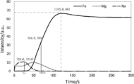
- FIG. 1 is an example of the elemental profile measured in the grain oriented electrical steel sheet of a comparative example.
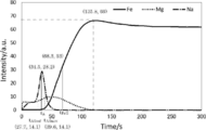
- FIG. 2 is an example of the element profile measured in the grain-oriented electrical steel sheet of the present invention. 1 and 2 are both graphs showing profiles of Fe, Mg and Na.
- the sample of the grain oriented electrical steel sheet was produced as follows. First, a finish-annealed grain-oriented electrical steel sheet having a thickness of 0.23 mm manufactured by a known method is sheared to a size of 300 mm (rolling direction) x 100 mm (rolling perpendicular direction), and unreacted After removing the annealing separator, strain relief annealing was performed under the condition of N 2 atmosphere at 800 ° C. for 2 hours. A film A containing forsterite as crystalline was formed on the surface of the steel plate. Next, light acid washing was performed using a 5% by mass aqueous phosphoric acid solution. After light acid washing, in the comparative example of FIG.
- the coating amount (both sides) as NaOH was made 0.01 g / m 2 by immersing in a 10% by mass aqueous solution of NaOH at 25 ° C. for 5 seconds and then washing with water. . Thereafter, an aqueous solution obtained by mixing an aqueous solution of magnesium phosphate (100 parts by mass in terms of solid content), colloidal silica (50 parts by mass in terms of solid content), and CrO 3 (15 parts by mass) is diluted with pure water The specific gravity was adjusted to 1.20 g / cc to obtain a coating solution.
- the obtained coating solution was applied onto both sides of the coated steel sheet with a coating using a roll coater such that the coated amount after drying on both sides was 10 g / m 2 .
- the coated A-coated steel plate coated with the coating solution was loaded into a drying oven, dried at 300 ° C. for 1 minute, and then baked at 800 ° C. for 2 minutes under the condition of 100% N 2 .
- a coating B containing silica glass as glass was formed on the coating A.
- a sample of the grain-oriented electrical steel sheet (coating B / coating A / steel sheet) thus obtained was obtained.
- the half-value time t Fe / 2 of the profile of Fe is taken as the time (time on the surface side) showing a half intensity value of the intensity value of the peak. If the Fe profile does not have a peak, do as follows. First, long-time sputtering is performed, and it is waited until the sputtering reaches the steel plate (base iron) sufficiently and the emission intensity of Fe becomes a constant value.
- the time on the most surface side (film B side) indicating a half intensity value of the emission intensity (intensity value) of Fe which has become a constant value is taken as a half-value time t Fe / 2 of the profile of Fe .
- Peak time t A of the profile of alkali metal elements is the peak time when there is one peak, and the peak time of the highest peak when there are multiple peaks. I assume.
- ⁇ half-value time t A / 2 of the profile of the alkali metal element shows half the intensity value of the intensity value of the peak (if there is one peak, its peak, or the highest peak if there are multiple peaks) It will be time. Furthermore, the half value time of the surface side (coating B side) is t A / 2sur , and the half value time of the steel plate side is t A / 2met .
- t A / 2 is a concept including both t A / 2sur and t A / 2met .
- t A / t Fe / 2 is 0.35 or more and 0.75 or less, the alkali metal element is concentrated at the interface between the coating A and the coating B. In this case, the wettability of the interface between the coating A and the coating B is good, and the adhesion between the coating A and the coating B is excellent. In addition, the state in which a large amount of the alkali metal element is contained only in the film B is avoided, and the tension applied to the steel plate is excellent. Furthermore, the state in which the alkali metal element infiltrates into the film A is avoided, and the adhesion between the film A and the steel plate is excellent.
- t A / t Fe / 2 is preferably 0.40 or more and 0.75 or less.
- t A / 2sur / t Fe / 2 is less than 0.25 (that is, the profile of the alkali metal element is broad), it can be said that the alkali metal element is concentrated at the interface between the coating A and the coating B. Since the alkali metal element is mainly contained only in the film B and has the effect of improving the adhesion, the tension applied to the steel sheet is insufficient.
- t A / 2met / t Fe / 2 is larger than 1.00, the infiltration amount of the alkali metal element to the film A is large, the alkali metal element is concentrated at the crystal interface, and the grain boundary strength decreases. The adhesion between the coating A and the steel plate is poor.
- t A / 2 / t Fe / 2 (that is, both t A / 2sur / t Fe / 2 and t A / 2met / t Fe / 2 ) is 0.25 or more and 1.00 or less If it is, as in formula (1), the alkali metal element is concentrated at the interface between the coating A and the coating B. In this case, the wettability of the interface between the coating A and the coating B is good, and the adhesion between the coating A and the coating B is excellent. In addition, the state in which a large amount of the alkali metal element is contained only in the film B is avoided, and the tension applied to the steel plate is excellent.
- the state in which the alkali metal element infiltrates into the film A is avoided, and the adhesion between the film A and the steel plate is excellent. 0.30 or more and 0.90 or less are preferable for tA / 2 / tFe / 2 .
- Examples of the alkali metal element include Li, Na, K, Rb, Cs, and Fr.
- the alkali metal element that is, the alkali metal element to be concentrated at the interface between the coating A and the coating B
- the alkali metal element include Li, Na, K, Rb, Cs, and Fr.
- at least one selected from the group consisting of Li, Na, and K is preferable because it is superior in price and availability to Rb, Cs, and Fr, and the tension applied to the steel plate is higher than Li.
- at least one selected from the group consisting of Na and K is more preferable.
- the steel plate is not particularly limited.
- a steel slab to be a steel plate has, as a component in the steel, C: 0.001 to 0.10%, Si: 1.0 to 5.0%, by mass%, by mass 0.01 to 1.0%, sol. Al: 0.003 to 0.050%, N: 0.001 to 0.020%, S: 0.001 to 0.05%, and / or Se: 0.001 to 0.05% It is preferable from the viewpoint of the magnetic properties that the balance consists of inevitable enemy and Fe.
- C is a component useful for generation of Goss-oriented crystal grains, and in order to exert this effect effectively, the C content is preferably 0.001% by mass or more.
- the C content is preferably 0.10 mass% or less.
- Si is a component necessary to enhance the electrical resistance and reduce iron loss, and stabilize the BCC structure of iron to enable high temperature heat treatment, and the Si content is 1.0% by mass or more. Is preferable, and 2.0 mass% or more is more preferable.
- the content of Si is preferably 5.0% by mass or less.
- Mn not only contributes effectively to the improvement of the hot embrittlement of the steel, but also forms precipitates such as MnS and MnSe when S and Se are mixed, and functions as an inhibitor (inhibitor). Demonstrate.
- the Mn content is preferably 0.01% by mass or more.
- the Mn content is preferably 1.0% by mass or less.
- Al is a useful component that forms AlN in steel and exhibits the action of an inhibitor as a dispersed second phase.
- the Al content is preferably 0.003 to 0.050% by mass.
- N like Al, is a component for forming AlN. When N is too small, precipitation of AlN may be insufficient. On the other hand, if N is too large, blistering may occur at the time of slab heating. Therefore, the N content is preferably 0.001 to 0.020 mass%.
- S and Se combine with Mn and Cu to form MnSe, MnS, Cu 2-x Se, Cu 2-x S, etc., and are useful components that exhibit the action of an inhibitor as a dispersed second phase in steel. is there. If the amount of S and / or Se is too small, the effect of addition may be insufficient, and if too large, solid solution at the time of slab heating may be incomplete or it may cause defects on the product surface. Therefore, the content of S and / or Se is preferably 0.001 to 0.05% by mass.
- the steel slab to be a steel plate further contains, in mass%, Cu: 0.01 to 0.2%, Ni: 0.01 to 0.5%, Cr: 0.01 to 0.5%, Sb: 0. At least one selected from the group consisting of 01 to 0.1%, Sn: 0.01 to 0.5%, Mo: 0.01 to 0.5%, and Bi: 0.001 to 0.1%.
- the magnetic properties can be further improved by adding an element having an action as a supplementary inhibitor.
- the above-mentioned elements are mentioned as such an element. If any of the elements is less than the above content, the effect is hardly obtained. On the other hand, if the content is exceeded, defects in the appearance of the film and secondary recrystallization defects may easily occur. Therefore, the content is preferably in the above range.
- the steel slab to be a steel plate is, by mass%, B: 0.001 to 0.01%, Ge: 0.001 to 0.1%, As: 0.005 to 0.1 %, P: 0.005 to 0.1%, Te: 0.005 to 0.1%, Nb: 0.005 to 0.1%, Ti: 0.005 to 0.1%, and V: It can contain at least one element selected from the group consisting of 0.005 to 0.1%. Thereby, the suppression force is further strengthened, and a higher magnetic flux density can be stably obtained.
- the steel plate is manufactured, for example, as follows. First, the steel slab is subjected to hot rolling to obtain a hot-rolled sheet.
- the hot-rolled sheet is optionally subjected to hot-rolled sheet annealing, and then subjected to one or two or more cold rollings sandwiching the intermediate annealing to obtain a cold-rolled sheet having a final thickness.
- the cold rolled sheet is subjected to primary recrystallization annealing and decarburization annealing (it is common that primary recrystallization annealing also serves as decarburization annealing), and then an annealing separator is applied and then final finish annealing is applied.
- a steel plate (oriented electrical steel sheet) in which Goth-oriented crystal grains (secondary recrystallized grains) are developed is obtained.
- manufacturing conditions conventionally well-known conditions can be employ
- a forsterite-containing film is formed on the surface of the obtained steel sheet.
- a film (cordierite film) containing cordierite is formed on the surface of the obtained steel sheet.
- the forsterite film and the cordierite film correspond to the film A described later. When these films are used as the film A, the film B described later is formed as it is.
- these films are removed by pickling or the like, and then another film A (for example, a film A containing a nitride described later) is formed, and then a film described later Form B
- a directional electromagnetic steel plate (steel plate), without forming these films.
- Film A is a film containing crystalline material disposed on a steel plate.
- the method for producing the film A is not particularly limited, and methods other than those described above include, for example, CVD (Chemical Vapor Deposition) method, PVD (Physical Vapor Deposition) method, sol gel method, steel plate oxidation method and the like. It can be mentioned.
- Examples of the crystalline material of the film A include oxides, and specific examples thereof preferably include at least one selected from the group consisting of forsterite and cordierite.
- Coating A containing forsterite as a crystalline oxide is the above-described forsterite coating.
- Coating A containing cordierite as a crystalline oxide is the cordierite coating described above. The method for obtaining these coatings is as described above.
- the crystalline quality of the film A may be a nitride.
- the nitride include metal nitrides.
- the metal nitride is preferably a metal nitride containing at least one metal selected from the group consisting of Ti, Al and Cr, and is made of titanium nitride (TiN), aluminum nitride (AlN) and chromium nitride (CrN). At least one selected from the group is more preferred.
- the film A containing nitride is formed by, for example, a CVD method or a PVD method.
- the crystalline content in the film A can be measured by X-ray diffraction using a calibration curve.
- the coating A may have two or more layers.
- the film thickness on one side of the film A (in the case of two or more layers, the total film thickness of each layer) is not particularly limited, but is preferably 0.05 to 5.00 ⁇ m, and more preferably 0.10 to 3.00 ⁇ m.
- the film B is a film containing vitreous material disposed on the film A, and is a so-called insulating tension film.
- the glass of the coating B include silica phosphate glass, and specific examples thereof include Mg, Al, Ca, Ti, Nd, Mo, Cr, B, Ta, Cu and Mn.
- a preferred example is a silicon phosphate glass containing at least one selected metal element. From the viewpoint of recent environmental regulations, it is more preferable not to contain Cr.
- the coating B may contain crystalline (except for the crystalline contained in the coating A).
- the balance other than glass is crystalline.
- the vitreous content of the film B is preferably 10 to 100% by mass because the film adhesion between the film A and the film B may be degraded if the content is less than 10% by mass.
- the content of glass in the film B is more preferably 30 to 90% by mass, and still more preferably 40 to 70% by mass or more.
- the method to form the film B is not particularly limited, for example, a method (method B1) of obtaining the film B by applying a coating liquid on the film A and then baking it may be mentioned.
- the baking may be planarization annealing which also serves as baking.
- the coating solution preferably contains phosphoric acid and / or phosphate and colloidal silica.
- metal species of phosphate include Mg, Al, Ca, Mn, Ni and the like.
- the coating solution can further contain a metal compound.
- the metal species of the metal compound include at least one selected from the group consisting of Mg, Al, Ca, Ti, Nd, Mo, Cr, B, Ta, Cu and Mn.
- B (boron) is treated as a metal.
- the content of each component in the coating liquid is not particularly limited, and can be set as appropriate.
- the baking temperature is, for example, 600 to 1000 ° C.
- the baking time is, for example, 1 to 300 seconds.
- the baking atmosphere is, for example, a nitrogen atmosphere.
- the method of forming the film B may be a method (method B2) of obtaining the film B by applying a glass frit on the film A and then baking it.
- the glass frit contains, for example, PbO, SiO 2 , B 2 O 3 , BaO, ZnO or the like on an oxide basis.
- the baking temperature is, for example, 600 to 1,200.degree.
- the baking time is, for example, 5 to 20 minutes.
- the baking atmosphere is, for example, a nitrogen atmosphere.
- the coating B may have two or more layers.
- the film thickness on one side of the film B (in the case of two or more layers, the total film thickness of each layer) is preferably 1.0 to 6.0 ⁇ m, from the viewpoint of obtaining a good interlayer resistance and space factor, 1.5 It is more preferable to be -4.0 ⁇ m.
- the tension applied to the steel sheet by the film B is, for example, 8 MPa or more, preferably 10 MPa or more, and more preferably 12 MPa or more.
- the method of producing the grain oriented electrical steel sheet of the present invention is a method comprising the steps of obtaining a steel sheet with a coating A and forming a coating B on the coating A of the steel sheet with a coating A.
- the method of adjusting the profile of the alkali metal element is not particularly limited in order to satisfy the formulas (1) and (2) described above, but, for example, methods 1 to 3 described below can be mentioned.
- Method 1 is a method of immersing the steel sheet with film A in an aqueous solution of an alkali metal compound, and then washing with water and drying before forming the film B. At this time, the profile of the alkali metal element is adjusted by adjusting the washing conditions such as the washing time.
- alkali metal compound examples include, but are not limited to, for example, LiOH, NaOH, KOH, Li 2 SO 4 , Na 2 SO 4 , K 2 SO 4 , LiCl, NaCl, Na 2 HPO 4 , K 2 HPO 4 and the like. Can be mentioned.
- the content of the alkali metal compound in the aqueous solution in which the coated steel sheet with a coating A is immersed is preferably 1% by mass or more, and more preferably 5% by mass or more, because the basis weight described later can be easily obtained.
- the content is preferably 40% by mass or less, more preferably 30% by mass or less, because the amount of removal of the alkali metal compound by washing with water is not too large and is economical.
- the temperature of the aqueous solution of the alkali metal compound for immersing the coated steel A-coated steel sheet is preferably 10 ° C. or higher, and more preferably 15 ° C. or higher because the basis weight described later can be easily obtained.
- this temperature is preferably 80 ° C. or less, more preferably 70 ° C. or less, because anions such as OH ⁇ , SO 4 2 ⁇ and Cl ⁇ of the alkali metal compound are less likely to corrode the coating A and the steel plate.
- the time (immersion time) for immersing the steel sheet with film A in an aqueous solution of an alkali metal compound is not particularly limited, and is, for example, 1 to 60 seconds, preferably 5 to 30 seconds.
- the coating weight of the alkali metal compound in terms of alkali metal element in the coated A-coated steel sheet after drying is, for example, 1.0 ⁇ 10 ⁇ 6 mol / m 2 or more on both sides, and the coating adhesion becomes better. For this reason, 1.0 ⁇ 10 ⁇ 5 mol / m 2 or more is preferable.
- the upper limit of the coating weight is not particularly limited, but is, for example, 1.0 ⁇ 10 ⁇ 2 mol / m 2 or less.
- the weight per unit area of the alkali metal compound in terms of an alkali metal element can be obtained from the mass change of the coated steel sheet A before and after treatment (immersion in an aqueous solution of alkali metal compound, water washing and drying).
- a calibration curve is created from the fluorescent X-ray counts of the alkali metal element.
- the basis weight of the above alkali metal compound in terms of alkali metal element can be simply measured.
- a coating solution or the like is applied and baked on the film A to form a film B.
- the baking conditions such as the baking time of the film B, the diffusion of the alkali metal element can be controlled, and the distribution of the alkali metal element can be adjusted.
- Method 2 is a method in which a coating solution B is applied and baked multiple times to form a plurality of layers of film B on the film A.
- Colloidal silica used for a coating liquid may contain alkali metal elements, such as Na.
- the amount of alkali metal element of colloidal silica used for the coating B of the first layer is made larger than that of the second layer. Thereby, the profile of the alkali metal element is adjusted to satisfy the above-mentioned formulas (1) and (2).
- Method 3 is a method of forming a plurality of coatings B on the coating A by applying and baking a glass frit a plurality of times.
- an alkali metal compound such as KOH or NaOH is added to the glass frit used for the first coating film B.
- the profile of the alkali metal element is adjusted to satisfy the above-mentioned formulas (1) and (2).
- Si 3.3%, C: 0.06%, Mn: 0.08%, S: 0.001%, Al: 0.015%, N: 0.006%, Cu:
- a silicon steel slab containing 0.05% and Sb: 0.01% was prepared.
- the silicon steel slab was heated at 1100 ° C. for 30 minutes and then subjected to hot rolling to obtain a hot-rolled sheet having a thickness of 2.2 mm.
- the obtained hot-rolled sheet was subjected to annealing at 1000 ° C. for 1 minute and then subjected to cold rolling to obtain a cold-rolled sheet coil having a final thickness of 0.27 mm.
- a cold-rolled sheet sample having a size of 100 mm (in the direction perpendicular to rolling) ⁇ 400 mm (in the direction of rolling) was collected.
- the collected cold rolled sheet sample was heated from room temperature to 820 ° C. in a laboratory at a heating rate of 20 ° C./s, and subjected to primary recrystallization annealing at 820 ° C. for 60 seconds in a wet atmosphere.
- an annealing separator in which 10 parts by mass of TiO 2 was mixed with 100 parts by mass of MgO was applied on the surface of the cold-rolled sheet sample subjected to primary recrystallization annealing after making it into a water slurry, and then dried. After raising the temperature of the cold-rolled sheet sample after drying between 300 ° C. and 800 ° C. over 100 hours, the temperature is raised to 1200 ° C. at 50 ° C./hr, and final annealing is performed at 1200 ° C. for 5 hours I did. Thus, a film A (forsterite film) containing forsterite as a crystalline substance was formed, and a steel plate with the film A was obtained. The film thickness of the film A (forsterite film) was 1.20 ⁇ m. The crystalline content of the coating A was 80% by mass or more.
- the obtained steel sheet with film A was immersed in a 5% by mass aqueous solution of an alkali metal compound described in Table 1 below at 25 ° C. for 10 seconds. Thereafter, it was washed with pure water and dried. At this time, by adjusting the degree of washing with water, the coated amount (both sides) in terms of alkali metal element of the alkali metal compound after drying was adjusted. The basis weight was measured by the method described above.
- a silica phosphate-based insulation tension containing magnesium phosphate (30 mol% in Mg (PO 3 ) 2 conversion), colloidal silica (60 mol% in SiO 2 conversion), and CrO 3 (10 mol%) A coating solution was prepared.
- the prepared coating solution was applied onto film A and baked at 850 ° C. Thereby, on the film A, a film B containing silica glass as glass was formed. At this time, the baking time (unit: s (seconds)) described in Table 1 below was used.
- colloidal silica colloidal silica “Snowtex-O” (Na content: 0.03 mass%) manufactured by Nissan Chemical Industries, Ltd., which is an acidic type having a low Na content, was used.
- the amount of coating solution applied was 10 g / m 2 on both sides.
- the film thickness of the film B was 2.5 ⁇ m on one side.
- ⁇ Covering width A sample of the produced grain oriented electrical steel sheet was sheared in the thickness direction using a shearing machine. Thereafter, the processing end is observed using a metallurgical microscope, and the distance (the distance from the processing end face) at which the coating (at least one of the coatings A and B) is peeled off at the processing end is measured. It was set as the film peeling width (unit: mm) of the part. It can be evaluated that the film adhesion is excellent as the film peeling width is smaller, and for practical use, the film peeling width is preferably less than 3.0 mm.
- Bending peeling diameter A strain relief annealing was performed in a nitrogen atmosphere at 800 ° C. for 3 hours on a sample of the produced grain-oriented electrical steel sheet. Thereafter, the sample was wound around a plurality of round bars having different diameters in units of 10 mm, and the minimum diameter (bending peeling diameter) at which peeling or cracking did not occur in the coating (at least one of the coating A and B) was determined. It can be evaluated that the smaller the bending peeling diameter (unit: mm), the better the film adhesion, and the practically preferable bending peeling diameter is less than 40 mm.
- ⁇ tension applied ⁇ tension applied >> First, a corrosion prevention tape was attached to one side (entire surface) of a sample of the produced grain-oriented electrical steel sheet. Thereafter, the sample with the corrosion prevention tape attached thereto was immersed in a 25% by mass aqueous NaOH solution at 110 ° C. for about 10 minutes to remove the coating B on the side to which the corrosion prevention tape was not attached. By removing the coating B on one side, the sample warped. The corrosion protection tape was removed and the radius of curvature of the sample was measured. The applied tension (unit: MPa) to the steel plate by the coating B was determined from the measured radius of curvature. The applied tension is preferably 8.0 MPa or more.
- No. 2 had a large film peeling width and bending peeling diameter, and had poor film adhesion.
- the tension applied to the steel plate was insufficient.
- No. 12 had a large film peeling width and bending peeling diameter, and had poor film adhesion.
- the prepared coating solution was applied to the surface of the obtained coated A-coated steel sheet and baked.
- the application and baking were performed twice.
- the colloidal silica of the coating solution colloidal silica “AT-300” (Na content: 0.55% by mass) manufactured by Adeka is used for the first coating B, and the second coating B is used.
- colloidal silica "AT-20N” (Na content: 0.03% by mass) manufactured by ADEKA Corporation was used.
- the baking conditions of the film B were a nitrogen atmosphere for 30 seconds at 900 ° C. for both the first and second layers.
- the film thickness (one side, unit: ⁇ m) of the film B was as described in Table 2 below. The film thickness was evaluated by cross-sectional SEM observation.
- a silicon steel slab containing 0.05% and Sb: 0.01% was prepared.
- the silicon steel slab was heated at 1100 ° C. for 30 minutes and then subjected to hot rolling to obtain a hot-rolled sheet having a thickness of 2.2 mm.
- the obtained hot-rolled sheet was annealed at 1000 ° C. for 1 minute and then cold-rolled to obtain a cold-rolled sheet having a final thickness of 0.23 mm. Subsequently, the cold rolled sheet was heated from room temperature to 820 ° C.
- annealing in which 150 parts by mass of Al 2 O 3 and 1 part by mass of Na 2 B 4 O 7 ⁇ 10H 2 O are mixed with 50 parts by mass of MgO.
- the separating agent was slurried in water, then applied and dried. After raising the temperature of the cold rolled sheet after drying between 300 ° C. and 800 ° C. over 100 hours, the temperature is raised to 1200 ° C.
- cordierite as crystalline (2MgO ⁇ 2Al 2 O 3 ⁇ 5SiO 2) steel plates with coating A comprising (coil). From the center of the obtained coil, a sample having a size of 100 mm (in the direction perpendicular to rolling) ⁇ 400 mm (in the direction of rolling) was taken. In some samples, the film A (cordierite film) was peeled off using a mixed acid of sulfuric acid and hydrofluoric acid, and a film A containing a nitride shown in Table 3 below as crystalline using a PVD method The nitride film was formed. The film thickness (unit: ⁇ m) of the film A is shown in Table 3 below. The crystalline content in the film A was 80% by mass or more in all cases.
- a glass frit manufactured by Asahi Glass Co., Ltd. described in Table 3 below was applied onto the surface of the steel sheet with the coating A, and the coating B was formed by baking.
- the glass frit had a large particle size, and was ground using a ball mill to adjust the particle size to an average particle size of 1.0 ⁇ m before use.
- the application and baking were performed twice to form a two-layer film B.
- 0.2 mass% KOH was added to a glass frit.
- the baking conditions of the film B were a nitrogen atmosphere for 10 minutes at 1000 ° C. in both the first and second layers.
- the film thickness (one side, unit: ⁇ m) of the film B was as described in Table 3 below. The film thickness was evaluated by cross-sectional SEM observation.
Landscapes
- Chemical & Material Sciences (AREA)
- Engineering & Computer Science (AREA)
- Mechanical Engineering (AREA)
- Materials Engineering (AREA)
- Metallurgy (AREA)
- Organic Chemistry (AREA)
- Chemical Kinetics & Catalysis (AREA)
- General Chemical & Material Sciences (AREA)
- Physics & Mathematics (AREA)
- Thermal Sciences (AREA)
- Crystallography & Structural Chemistry (AREA)
- Inorganic Chemistry (AREA)
- Electromagnetism (AREA)
- Power Engineering (AREA)
- Dispersion Chemistry (AREA)
- Manufacturing & Machinery (AREA)
- Ceramic Engineering (AREA)
- Chemical Treatment Of Metals (AREA)
- Soft Magnetic Materials (AREA)
- Manufacturing Of Steel Electrode Plates (AREA)
Abstract
Priority Applications (6)
| Application Number | Priority Date | Filing Date | Title |
|---|---|---|---|
| JP2018568983A JP6573042B1 (ja) | 2017-11-28 | 2018-10-12 | 方向性電磁鋼板およびその製造方法 |
| CN201880075675.9A CN111406126B (zh) | 2017-11-28 | 2018-10-12 | 取向性电磁钢板及其制造方法 |
| US16/766,090 US11473176B2 (en) | 2017-11-28 | 2018-10-12 | Oriented electrical steel sheet and method for producing same |
| KR1020207013522A KR102432967B1 (ko) | 2017-11-28 | 2018-10-12 | 방향성 전기 강판 및 그 제조 방법 |
| RU2020117184A RU2736247C1 (ru) | 2017-11-28 | 2018-10-12 | Текстурированная электротехническая листовая сталь и способ ее производства |
| EP18884687.7A EP3719169A4 (fr) | 2017-11-28 | 2018-10-12 | Tôle magnétique en acier à grains orientés et son procédé de production |
Applications Claiming Priority (2)
| Application Number | Priority Date | Filing Date | Title |
|---|---|---|---|
| JP2017228001 | 2017-11-28 | ||
| JP2017-228001 | 2017-11-28 |
Publications (1)
| Publication Number | Publication Date |
|---|---|
| WO2019106976A1 true WO2019106976A1 (fr) | 2019-06-06 |
Family
ID=66664825
Family Applications (1)
| Application Number | Title | Priority Date | Filing Date |
|---|---|---|---|
| PCT/JP2018/038133 Ceased WO2019106976A1 (fr) | 2017-11-28 | 2018-10-12 | Tôle magnétique en acier à grains orientés et son procédé de production |
Country Status (7)
| Country | Link |
|---|---|
| US (1) | US11473176B2 (fr) |
| EP (1) | EP3719169A4 (fr) |
| JP (1) | JP6573042B1 (fr) |
| KR (1) | KR102432967B1 (fr) |
| CN (1) | CN111406126B (fr) |
| RU (1) | RU2736247C1 (fr) |
| WO (1) | WO2019106976A1 (fr) |
Cited By (4)
| Publication number | Priority date | Publication date | Assignee | Title |
|---|---|---|---|---|
| CN115135794A (zh) * | 2019-12-19 | 2022-09-30 | Posco公司 | 无取向电工钢板及其制造方法 |
| WO2023112421A1 (fr) * | 2021-12-14 | 2023-06-22 | Jfeスチール株式会社 | Tôle d'acier électromagnétique à grains orientés et son procédé de production |
| JPWO2024210186A1 (fr) * | 2023-04-05 | 2024-10-10 | ||
| WO2024210187A1 (fr) * | 2023-04-05 | 2024-10-10 | 日本製鉄株式会社 | Liquide de traitement de revêtement d'isolation pour tôle d'acier électromagnétique à grains orientés, son procédé de production et procédé de production de tôle d'acier électromagnétique à grains orientés |
Citations (7)
| Publication number | Priority date | Publication date | Assignee | Title |
|---|---|---|---|---|
| JPS4839338A (fr) | 1971-09-27 | 1973-06-09 | ||
| JPS5079442A (fr) | 1973-11-17 | 1975-06-27 | ||
| JPH0867913A (ja) | 1994-08-24 | 1996-03-12 | Nippon Steel Corp | 鉄損の小さい珪素鋼板及びその製造法及び使用法 |
| JPH08325745A (ja) * | 1995-05-26 | 1996-12-10 | Nippon Steel Corp | 低鉄損一方向性珪素鋼板およびその製造方法 |
| JPH1171683A (ja) | 1997-08-28 | 1999-03-16 | Nippon Steel Corp | 高張力絶縁被膜を有する方向性電磁鋼板とその処理方法 |
| JP2015147988A (ja) * | 2014-02-07 | 2015-08-20 | Jfeスチール株式会社 | 方向性電磁鋼板およびその製造方法 |
| JP2017122247A (ja) * | 2016-01-05 | 2017-07-13 | Jfeスチール株式会社 | 方向性電磁鋼板の製造方法 |
Family Cites Families (21)
| Publication number | Priority date | Publication date | Assignee | Title |
|---|---|---|---|---|
| GB1234181A (fr) * | 1967-06-14 | 1971-06-03 | ||
| EP0193324B1 (fr) * | 1985-02-22 | 1989-10-11 | Kawasaki Steel Corporation | Tôles d'acier au silicium à grains orientés et à pertes dans le fer extrêmement faibles |
| CN1039915C (zh) | 1989-07-05 | 1998-09-23 | 新日本制铁株式会社 | 方向性电磁钢板上的绝缘皮膜成型方法 |
| JPH0483938A (ja) | 1990-07-26 | 1992-03-17 | Nobuaki Debari | 回転体のバランス調節機構 |
| JPH0579442A (ja) | 1991-09-19 | 1993-03-30 | Hitachi Ltd | 点火用配電器のロータヘツド |
| US5411808A (en) | 1992-02-13 | 1995-05-02 | Nippon Steel Corporation | Oriented electrical steel sheet having low core loss and method of manufacturing same |
| WO1998044517A1 (fr) * | 1997-04-03 | 1998-10-08 | Kawasaki Steel Corporation | Tole d'acier au silicium unidirectionnel a perte ultra-faible dans le fer |
| DE69913624T2 (de) * | 1998-09-18 | 2004-06-09 | Jfe Steel Corp. | Kornorientieres Siliziumstahlblech und Herstellungsverfahren dafür |
| JP4259037B2 (ja) | 2002-05-21 | 2009-04-30 | Jfeスチール株式会社 | 方向性電磁鋼板の製造方法 |
| JP4012483B2 (ja) * | 2003-04-15 | 2007-11-21 | 新日本製鐵株式会社 | 一方向性電磁鋼板の絶縁皮膜形成方法、および皮膜密着性に優れた絶縁皮膜を有する一方向性電磁鋼板 |
| TWI270578B (en) | 2004-11-10 | 2007-01-11 | Jfe Steel Corp | Grain oriented electromagnetic steel plate and method for producing the same |
| EP2096185B1 (fr) | 2006-11-22 | 2014-08-13 | Nippon Steel & Sumitomo Metal Corporation | Feuille d'acier électromagnétique à orientation unidirectionnelle de grains, ayant une excellente adhésion de film, et son procédé de fabrication |
| EP2799594B1 (fr) * | 2011-12-28 | 2018-10-31 | JFE Steel Corporation | Tôle d'acier électromagnétique directionnelle ayant un revêtement, et son procédé de fabrication |
| JP6031951B2 (ja) * | 2012-11-09 | 2016-11-24 | Jfeスチール株式会社 | 方向性電磁鋼板およびその製造方法 |
| DE102013107506A1 (de) * | 2013-07-16 | 2015-01-22 | Thyssenkrupp Rasselstein Gmbh | Verfahren zur Passivierung von bandförmigem Schwarzblech |
| JP6156646B2 (ja) * | 2013-10-30 | 2017-07-05 | Jfeスチール株式会社 | 磁気特性および被膜密着性に優れる方向性電磁鋼板 |
| BR112017003450B1 (pt) | 2014-09-01 | 2021-06-22 | Nippon Steel Corporation | Chapa de aço elétrico com grão orientado e método de produção da referida chapa |
| JP6168173B2 (ja) * | 2015-01-30 | 2017-07-26 | Jfeスチール株式会社 | 方向性電磁鋼板とその製造方法 |
| KR101952237B1 (ko) * | 2015-02-05 | 2019-02-26 | 제이에프이 스틸 가부시키가이샤 | 방향성 전자 강판 및 그의 제조 방법 그리고 변압기 소음 특성의 예측 방법 |
| JP6547835B2 (ja) * | 2015-09-29 | 2019-07-24 | 日本製鉄株式会社 | 方向性電磁鋼板、及び方向性電磁鋼板の製造方法 |
| WO2018123339A1 (fr) * | 2016-12-28 | 2018-07-05 | Jfeスチール株式会社 | Tôle d'acier électrique à grains orientés, noyau de transformateur, transformateur et procédé de réduction du bruit d'un transformateur |
-
2018
- 2018-10-12 WO PCT/JP2018/038133 patent/WO2019106976A1/fr not_active Ceased
- 2018-10-12 JP JP2018568983A patent/JP6573042B1/ja active Active
- 2018-10-12 RU RU2020117184A patent/RU2736247C1/ru active
- 2018-10-12 US US16/766,090 patent/US11473176B2/en active Active
- 2018-10-12 KR KR1020207013522A patent/KR102432967B1/ko active Active
- 2018-10-12 CN CN201880075675.9A patent/CN111406126B/zh active Active
- 2018-10-12 EP EP18884687.7A patent/EP3719169A4/fr active Pending
Patent Citations (7)
| Publication number | Priority date | Publication date | Assignee | Title |
|---|---|---|---|---|
| JPS4839338A (fr) | 1971-09-27 | 1973-06-09 | ||
| JPS5079442A (fr) | 1973-11-17 | 1975-06-27 | ||
| JPH0867913A (ja) | 1994-08-24 | 1996-03-12 | Nippon Steel Corp | 鉄損の小さい珪素鋼板及びその製造法及び使用法 |
| JPH08325745A (ja) * | 1995-05-26 | 1996-12-10 | Nippon Steel Corp | 低鉄損一方向性珪素鋼板およびその製造方法 |
| JPH1171683A (ja) | 1997-08-28 | 1999-03-16 | Nippon Steel Corp | 高張力絶縁被膜を有する方向性電磁鋼板とその処理方法 |
| JP2015147988A (ja) * | 2014-02-07 | 2015-08-20 | Jfeスチール株式会社 | 方向性電磁鋼板およびその製造方法 |
| JP2017122247A (ja) * | 2016-01-05 | 2017-07-13 | Jfeスチール株式会社 | 方向性電磁鋼板の製造方法 |
Non-Patent Citations (1)
| Title |
|---|
| See also references of EP3719169A4 |
Cited By (12)
| Publication number | Priority date | Publication date | Assignee | Title |
|---|---|---|---|---|
| CN115135794A (zh) * | 2019-12-19 | 2022-09-30 | Posco公司 | 无取向电工钢板及其制造方法 |
| CN115135794B (zh) * | 2019-12-19 | 2023-12-19 | Posco公司 | 无取向电工钢板及其制造方法 |
| WO2023112421A1 (fr) * | 2021-12-14 | 2023-06-22 | Jfeスチール株式会社 | Tôle d'acier électromagnétique à grains orientés et son procédé de production |
| JPWO2023112421A1 (fr) * | 2021-12-14 | 2023-06-22 | ||
| JP7529055B2 (ja) | 2021-12-14 | 2024-08-06 | Jfeスチール株式会社 | 方向性電磁鋼板およびその製造方法 |
| EP4417717A4 (fr) * | 2021-12-14 | 2025-04-23 | JFE Steel Corporation | Tôle d'acier électromagnétique à grains orientés et son procédé de production |
| JPWO2024210186A1 (fr) * | 2023-04-05 | 2024-10-10 | ||
| WO2024210186A1 (fr) * | 2023-04-05 | 2024-10-10 | 日本製鉄株式会社 | Liquide de traitement de formation de film isolant pour tôle d'acier électromagnétique à grains orientés et procédé de production de tôle d'acier électromagnétique à grains orientés |
| WO2024210187A1 (fr) * | 2023-04-05 | 2024-10-10 | 日本製鉄株式会社 | Liquide de traitement de revêtement d'isolation pour tôle d'acier électromagnétique à grains orientés, son procédé de production et procédé de production de tôle d'acier électromagnétique à grains orientés |
| JPWO2024210187A1 (fr) * | 2023-04-05 | 2024-10-10 | ||
| JP7810936B2 (ja) | 2023-04-05 | 2026-02-04 | 日本製鉄株式会社 | 方向性電磁鋼板用絶縁被膜処理液および方向性電磁鋼板の製造方法 |
| JP7810937B2 (ja) | 2023-04-05 | 2026-02-04 | 日本製鉄株式会社 | 方向性電磁鋼板用絶縁被膜処理液およびその製造方法、ならびに方向性電磁鋼板の製造方法 |
Also Published As
| Publication number | Publication date |
|---|---|
| JP6573042B1 (ja) | 2019-09-11 |
| US20200354821A1 (en) | 2020-11-12 |
| CN111406126B (zh) | 2022-04-29 |
| CN111406126A (zh) | 2020-07-10 |
| EP3719169A1 (fr) | 2020-10-07 |
| KR20200069342A (ko) | 2020-06-16 |
| RU2736247C1 (ru) | 2020-11-12 |
| JPWO2019106976A1 (ja) | 2019-12-12 |
| EP3719169A4 (fr) | 2021-01-13 |
| US11473176B2 (en) | 2022-10-18 |
| KR102432967B1 (ko) | 2022-08-16 |
Similar Documents
| Publication | Publication Date | Title |
|---|---|---|
| JP5181571B2 (ja) | 方向性電磁鋼板用クロムフリー絶縁被膜処理液および絶縁被膜付方向性電磁鋼板の製造方法 | |
| KR101763085B1 (ko) | 자기 특성 및 피막 밀착성이 우수한 방향성 전기 강판 | |
| JP6332453B2 (ja) | 絶縁被膜付き方向性電磁鋼板およびその製造方法 | |
| JP2009052060A (ja) | 方向性電磁鋼板用絶縁被膜処理液および絶縁被膜付方向性電磁鋼板の製造方法 | |
| JP6031951B2 (ja) | 方向性電磁鋼板およびその製造方法 | |
| JP6573042B1 (ja) | 方向性電磁鋼板およびその製造方法 | |
| JP6558325B2 (ja) | クロムフリー張力被膜形成用処理液、クロムフリー張力被膜付方向性電磁鋼板、クロムフリー張力被膜付方向性電磁鋼板の製造方法およびトランス用コア | |
| WO2020149351A1 (fr) | Procédé de fabrication de tôle d'acier électrique à grains orientés | |
| JP5272469B2 (ja) | 方向性電磁鋼板およびその製造方法 | |
| JP5262228B2 (ja) | 方向性電磁鋼板およびその製造方法 | |
| WO2019155858A1 (fr) | Tôle d'acier électromagnétique à revêtement isolant et son procédé de production | |
| JP2008240080A (ja) | 方向性電磁鋼板用絶縁被膜処理液および方向性電磁鋼板の製造方法 | |
| JP6332452B2 (ja) | 絶縁被膜付き方向性電磁鋼板およびその製造方法 | |
| JP4635457B2 (ja) | クロムを含まず耐吸湿性に優れたリン酸塩系絶縁被膜を有する方向性電磁鋼板およびクロムを含まず耐吸湿性に優れたリン酸塩系絶縁被膜の被成方法。 | |
| JP2003171773A (ja) | 張力皮膜を有する一方向性珪素鋼板 | |
| JP7222450B1 (ja) | 前処理液および絶縁被膜付き電磁鋼板の製造方法 | |
| JP7311075B1 (ja) | 前処理液および絶縁被膜付き電磁鋼板の製造方法 | |
| CN114106593B (zh) | 一种用于取向硅钢表面涂层的涂料、取向硅钢板及其制造方法 | |
| JP7810937B2 (ja) | 方向性電磁鋼板用絶縁被膜処理液およびその製造方法、ならびに方向性電磁鋼板の製造方法 | |
| JP7855739B2 (ja) | コーティング材料、コーティング材料から形成されたコーティングを有する方向性ケイ素鋼板およびその製造方法 | |
| WO2020149327A1 (fr) | Procédé de fabrication de tôle d'acier électrique à grains orientés | |
| JP7473859B1 (ja) | 絶縁被膜付き電磁鋼板の製造方法 | |
| JP7810936B2 (ja) | 方向性電磁鋼板用絶縁被膜処理液および方向性電磁鋼板の製造方法 | |
| JP2003034880A (ja) | 方向性電磁鋼板の表面上に密着性に優れた絶縁被膜を形成する方法および方向性電磁鋼板の製造方法 | |
| WO2020149323A1 (fr) | Procédé de fabrication de tôle d'acier magnétique à grains orientés |
Legal Events
| Date | Code | Title | Description |
|---|---|---|---|
| ENP | Entry into the national phase |
Ref document number: 2018568983 Country of ref document: JP Kind code of ref document: A |
|
| 121 | Ep: the epo has been informed by wipo that ep was designated in this application |
Ref document number: 18884687 Country of ref document: EP Kind code of ref document: A1 |
|
| ENP | Entry into the national phase |
Ref document number: 20207013522 Country of ref document: KR Kind code of ref document: A |
|
| NENP | Non-entry into the national phase |
Ref country code: DE |
|
| ENP | Entry into the national phase |
Ref document number: 2018884687 Country of ref document: EP Effective date: 20200629 |