WO2019107231A1 - Puce microfluidique - Google Patents
Puce microfluidique Download PDFInfo
- Publication number
- WO2019107231A1 WO2019107231A1 PCT/JP2018/042916 JP2018042916W WO2019107231A1 WO 2019107231 A1 WO2019107231 A1 WO 2019107231A1 JP 2018042916 W JP2018042916 W JP 2018042916W WO 2019107231 A1 WO2019107231 A1 WO 2019107231A1
- Authority
- WO
- WIPO (PCT)
- Prior art keywords
- channel
- sub
- flow path
- branching
- microfluidic chip
- Prior art date
- Legal status (The legal status is an assumption and is not a legal conclusion. Google has not performed a legal analysis and makes no representation as to the accuracy of the status listed.)
- Ceased
Links
Images





Classifications
-
- B—PERFORMING OPERATIONS; TRANSPORTING
- B01—PHYSICAL OR CHEMICAL PROCESSES OR APPARATUS IN GENERAL
- B01L—CHEMICAL OR PHYSICAL LABORATORY APPARATUS FOR GENERAL USE
- B01L3/00—Containers or dishes for laboratory use, e.g. laboratory glassware; Droppers
- B01L3/50—Containers for the purpose of retaining a material to be analysed, e.g. test tubes
- B01L3/502—Containers for the purpose of retaining a material to be analysed, e.g. test tubes with fluid transport, e.g. in multi-compartment structures
- B01L3/5027—Containers for the purpose of retaining a material to be analysed, e.g. test tubes with fluid transport, e.g. in multi-compartment structures by integrated microfluidic structures, i.e. dimensions of channels and chambers are such that surface tension forces are important, e.g. lab-on-a-chip
- B01L3/502715—Containers for the purpose of retaining a material to be analysed, e.g. test tubes with fluid transport, e.g. in multi-compartment structures by integrated microfluidic structures, i.e. dimensions of channels and chambers are such that surface tension forces are important, e.g. lab-on-a-chip characterised by interfacing components, e.g. fluidic, electrical, optical or mechanical interfaces
-
- B—PERFORMING OPERATIONS; TRANSPORTING
- B01—PHYSICAL OR CHEMICAL PROCESSES OR APPARATUS IN GENERAL
- B01L—CHEMICAL OR PHYSICAL LABORATORY APPARATUS FOR GENERAL USE
- B01L3/00—Containers or dishes for laboratory use, e.g. laboratory glassware; Droppers
- B01L3/50—Containers for the purpose of retaining a material to be analysed, e.g. test tubes
- B01L3/502—Containers for the purpose of retaining a material to be analysed, e.g. test tubes with fluid transport, e.g. in multi-compartment structures
- B01L3/5027—Containers for the purpose of retaining a material to be analysed, e.g. test tubes with fluid transport, e.g. in multi-compartment structures by integrated microfluidic structures, i.e. dimensions of channels and chambers are such that surface tension forces are important, e.g. lab-on-a-chip
- B01L3/502723—Containers for the purpose of retaining a material to be analysed, e.g. test tubes with fluid transport, e.g. in multi-compartment structures by integrated microfluidic structures, i.e. dimensions of channels and chambers are such that surface tension forces are important, e.g. lab-on-a-chip characterised by venting arrangements
-
- B—PERFORMING OPERATIONS; TRANSPORTING
- B81—MICROSTRUCTURAL TECHNOLOGY
- B81B—MICROSTRUCTURAL DEVICES OR SYSTEMS, e.g. MICROMECHANICAL DEVICES
- B81B1/00—Devices without movable or flexible elements, e.g. microcapillary devices
-
- B—PERFORMING OPERATIONS; TRANSPORTING
- B01—PHYSICAL OR CHEMICAL PROCESSES OR APPARATUS IN GENERAL
- B01L—CHEMICAL OR PHYSICAL LABORATORY APPARATUS FOR GENERAL USE
- B01L2200/00—Solutions for specific problems relating to chemical or physical laboratory apparatus
- B01L2200/06—Fluid handling related problems
- B01L2200/0605—Metering of fluids
-
- B—PERFORMING OPERATIONS; TRANSPORTING
- B01—PHYSICAL OR CHEMICAL PROCESSES OR APPARATUS IN GENERAL
- B01L—CHEMICAL OR PHYSICAL LABORATORY APPARATUS FOR GENERAL USE
- B01L2200/00—Solutions for specific problems relating to chemical or physical laboratory apparatus
- B01L2200/14—Process control and prevention of errors
- B01L2200/141—Preventing contamination, tampering
-
- B—PERFORMING OPERATIONS; TRANSPORTING
- B01—PHYSICAL OR CHEMICAL PROCESSES OR APPARATUS IN GENERAL
- B01L—CHEMICAL OR PHYSICAL LABORATORY APPARATUS FOR GENERAL USE
- B01L2300/00—Additional constructional details
- B01L2300/04—Closures and closing means
- B01L2300/041—Connecting closures to device or container
-
- B—PERFORMING OPERATIONS; TRANSPORTING
- B01—PHYSICAL OR CHEMICAL PROCESSES OR APPARATUS IN GENERAL
- B01L—CHEMICAL OR PHYSICAL LABORATORY APPARATUS FOR GENERAL USE
- B01L2300/00—Additional constructional details
- B01L2300/08—Geometry, shape and general structure
- B01L2300/0809—Geometry, shape and general structure rectangular shaped
- B01L2300/0816—Cards, e.g. flat sample carriers usually with flow in two horizontal directions
-
- B—PERFORMING OPERATIONS; TRANSPORTING
- B01—PHYSICAL OR CHEMICAL PROCESSES OR APPARATUS IN GENERAL
- B01L—CHEMICAL OR PHYSICAL LABORATORY APPARATUS FOR GENERAL USE
- B01L2300/00—Additional constructional details
- B01L2300/08—Geometry, shape and general structure
- B01L2300/0809—Geometry, shape and general structure rectangular shaped
- B01L2300/0819—Microarrays; Biochips
-
- B—PERFORMING OPERATIONS; TRANSPORTING
- B01—PHYSICAL OR CHEMICAL PROCESSES OR APPARATUS IN GENERAL
- B01L—CHEMICAL OR PHYSICAL LABORATORY APPARATUS FOR GENERAL USE
- B01L2300/00—Additional constructional details
- B01L2300/08—Geometry, shape and general structure
- B01L2300/0861—Configuration of multiple channels and/or chambers in a single devices
- B01L2300/0864—Configuration of multiple channels and/or chambers in a single devices comprising only one inlet and multiple receiving wells, e.g. for separation, splitting
-
- B—PERFORMING OPERATIONS; TRANSPORTING
- B01—PHYSICAL OR CHEMICAL PROCESSES OR APPARATUS IN GENERAL
- B01L—CHEMICAL OR PHYSICAL LABORATORY APPARATUS FOR GENERAL USE
- B01L2400/00—Moving or stopping fluids
- B01L2400/06—Valves, specific forms thereof
- B01L2400/0688—Valves, specific forms thereof surface tension valves, capillary stop, capillary break
-
- G—PHYSICS
- G01—MEASURING; TESTING
- G01N—INVESTIGATING OR ANALYSING MATERIALS BY DETERMINING THEIR CHEMICAL OR PHYSICAL PROPERTIES
- G01N33/00—Investigating or analysing materials by specific methods not covered by groups G01N1/00 - G01N31/00
- G01N33/48—Biological material, e.g. blood, urine; Haemocytometers
- G01N33/483—Physical analysis of biological material
- G01N33/487—Physical analysis of biological material of liquid biological material
- G01N33/48707—Physical analysis of biological material of liquid biological material by electrical means
Definitions
- the present invention relates to a microfluidic chip having a flow path structure through which fluid is fed.
- microfluidic chips are known.
- a plurality of reaction vessels are provided in each of a plurality of branch channels branched from the main channel.
- the reagent liquid transfer system component for each sample and the control detection component are configured independently. Contamination between the reaction vessels is suppressed by using a backflow prevention valve on the upstream side and the downstream side of each reaction vessel.
- Patent Document 2 discloses that the movement of the fluid is prevented by using a gas generation valve.
- An object of the present invention is to provide a microfluidic chip which can reduce the number of valves for liquid transfer control and the like, can simplify a flow path structure, and can achieve further miniaturization. It is in.
- the microfluidic chip according to the present invention is a microfluidic chip having a flow path structure through which fluid is fed, the flow path structure including an inlet through which the fluid flows in, and an outlet through which the fluid flows out And a plurality of branch channels connected to the main channel, the side connected to the main channel being an inflow end, and the end opposite to the inflow end being an outflow end; Among the plurality of branch flow channels, between at least a pair of adjacent branch flow channels, there is a sub-branch flow channel connected to the main flow channel, and connected to the main flow channel of the sub-branch flow channel The side that is being used is the inflow end.
- the sub-branching channel does not have an outflow end.
- the inflow end of the sub-branching channel is opened on the inner wall surface of the main channel shared by the inflow ends of two or more branch channels. In this case, the contamination between the branch flow channels can be more effectively suppressed.
- the inner wall in which the branch flow channel and the sub branch flow channel are open is positioned in a direction orthogonal to the direction in which the branch flow channel extends. It is.
- the cross section of the main flow channel is rectangular.
- the sub-branching channels are provided at all positions between adjacent branching channels. In this case, contamination between all adjacent branch flow paths can be effectively suppressed.
- a portion having a flow passage cross-sectional area larger than the flow passage cross-sectional area at the inflow end connected to the main flow passage of the sub-branching flow passage It is provided in the branch flow path.
- the fluid can be reliably led to the sub-branching channel.
- the fluid led to the sub-branching channel is unlikely to leak out of the sub-branching channel. Therefore, contamination can be suppressed more reliably.
- the microfluidic chip further includes a connection flow path connected to the outflow end side of the plurality of branch flow paths, and the connection flow path is connected to the main flow path It is done.
- the inflow end and the outflow end of the main flow channel are provided with a seal capable of sealing the movement of fluid.
- the microfluidic chip according to the present invention does not require a valve or the like for liquid transfer control for each branch flow channel, so the number of valves or the like can be reduced, and the flow channel structure can be simplified. Can. In addition, miniaturization of the microfluidic chip can be promoted.
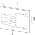
- FIG. 1 is a perspective view showing a microfluidic chip of a first embodiment of the present invention.
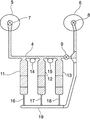
- FIG. 2 is a schematic plan view for explaining the flow channel structure in the microfluidic chip of the first embodiment of the present invention.
- FIG. 3 is a schematic plan view showing a state in which fluid is filled in a plurality of branch flow channels in the flow channel structure of the microfluidic chip according to the first embodiment of the present invention.
- FIG. 4 is a partial cutaway enlarged cross-sectional view for explaining the main flow channel and the sub-branch flow channel in the flow channel structure of the microfluidic chip of the first embodiment of the present invention.
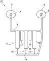
- FIG. 5 is a schematic plan view for explaining the flow channel structure of the microfluidic chip according to the second embodiment of the present invention.
- FIG. 6 is a schematic plan view for explaining the flow channel structure of the microfluidic chip according to the third embodiment of the present invention.
- FIG. 7 is a schematic plan view for explaining the flow channel structure of the microfluidic chip according to the fourth embodiment of the present invention.
- FIG. 8 is a schematic plan view for explaining the flow channel structure of the microfluidic chip according to the fifth embodiment of the present invention.
- FIG. 9 is a schematic plan view for explaining the flow channel structure of the microfluidic chip according to the sixth embodiment of the present invention.
- FIG. 10 is a schematic plan view for explaining the flow channel structure of the microfluidic chip according to the seventh embodiment of the present invention.
- FIG. 11 is a schematic plan view showing the flow channel structure of the microfluidic chip according to the eighth embodiment of the present invention.
- FIG. 12 is a perspective view showing a microfluidic chip according to a ninth embodiment of the present invention.
- FIG. 13 is a perspective view for explaining a method of using the microfluidic chip according to the ninth embodiment of the present invention so that the main channel is in the vertical direction.
- FIG. 1 is a perspective view showing a microfluidic chip according to a first embodiment of the present invention
- FIG. 2 is a schematic plan view showing the flow channel structure.
- the microfluidic chip 1 has a rectangular plate-shaped chip body 2.
- the chip body 2 is formed of a laminate formed by laminating a plurality of layers.
- the material which comprises this several layer consists of appropriate materials, such as a synthetic resin and glass.
- a flow path structure 3 shown by a broken line in FIG. 1 is provided in the chip main body 2, a flow path structure 3 shown by a broken line in FIG. 1 is provided.
- the flow path structure 3 is a portion to which the fluid is transported, and the flow path structure 3 has a main flow path 4.
- An inlet 5 is provided at one end of the main channel 4 and an outlet 6 is provided at the other end.
- a valve 7 is provided on the inlet 5 side, and a valve 8 is provided on the outlet 6 side.
- the valve 9 is provided on the downstream side of the main flow path 4 with respect to a portion to which a branch flow path 13 described later is connected. That is, the valve 9 is provided between the portion where the branch flow channel 13 is connected and the portion where the valve 8 is provided.
- valves 7, 8 and 9 constitute a sealing portion capable of sealing the main flow path 4.
- other sealing members capable of opening and closing the main flow path 4 by an operation from the outside may be used.
- branch flow channels 11 to 13 are connected to the main channel 4.
- the branch flow channels 11 to 13 are provided as reaction vessels for performing a PCR reaction.
- flow path resistance portions 16 to 18 having a smaller cross-sectional area than the branch flow paths 11 to 13 are provided ing.
- One end of each of the branch flow channels 11 to 13 is an inflow end, and is open to the main flow channel 4.
- the other ends of the branch flow paths 11 to 13 are outflow ends, and are connected to the flow path resistance portions 16 to 18.
- connection flow path 19 is connected to the main flow path 4 on the downstream side of the valve 9.
- the sub branch flow channel 14 is connected to the main flow channel 4 between the adjacent branch flow channels 11 and 12.
- the sub-branching channel 15 is connected to the main channel 4 also between the branch channels 12 and 13 adjacent to each other.
- the sub-branching channels 14 and 15 have an inlet end connected to the main channel 4, but the sub-branching channels 14 and 15 do not have a gas outlet. Further, the inflow ends of the sub-branching channels 14 and 15 open to the main channel 4.
- the sub-branching channel 14 is provided to prevent contamination of the sample or the reagent between the branching channels 11 and 12.
- the sub branch flow channel 15 is also provided to suppress contamination between adjacent branch flow channels 12 and 13.
- a fluid which is a liquid sample or liquid reagent is fed. More specifically, with the valves 7, 8 and 9 open, fluid is sent from the inlet 5 to the main flow channel 4.
- the fed fluid is filled in the branch channels 11, 12, 13 as shown in FIG. In this case, the liquid transfer is performed at a lower liquid transfer pressure than the flow path resistance of the flow path resistance portions 16-18. Therefore, the fluid is not sent to the flow path resistance portions 16-18.
- valve 8 When the valve 9 is closed, the valve 8 may also be closed.
- the fluid is sealed in the branch channels 11, 12, and 13.
- RNA or the like is polymeraseized, and the nucleic acid whose strand has been elongated is detected using an optical detection means or the like.
- the fluid as the reaction liquid is repeatedly heated in the branch channels 11, 12, 13 as described above. When the fluid is heated, it expands and tries to move from the branch flow channels 11 to 13 side to the main flow channel 4 side. Therefore, contamination may occur between the fluid in the branch flow channel 11 and the fluid in the branch flow channel 12.
- the sub branch flow channel 14 is provided between the adjacent branch flow channels 11 and 12. Therefore, even if there is a fluid that has expanded due to heating and has moved to the main flow path 4 side, it enters the sub-branch flow path 14 and does not reach the branch flow path 12 or the branch flow path 11 on the other side. Therefore, contamination between the fluids between adjacent branch flow channels 11 and 12 is unlikely to occur. Since the sub-branching channel 15 is provided between the adjacent branching channels 12 and 13, contamination can be similarly suppressed.
- FIG. 4 is a partial cutaway enlarged cross-sectional view corresponding to a portion along line AA of FIG.
- This cross section is a cross section of the main channel 4.
- the main flow path 4 has inner wall surfaces 4a to 4d.
- the inflow ends of the sub-branching channels 14 and 15 are opened in the inner wall surface 4a shared by the inflow ends of the plurality of branch channels 11-13.
- the sub-branching channels 14 and 15 are preferably connected to the same inner wall of the main channel 4 to which the branching channels 11 to 13 are connected.
- the main flow path 4 has a rectangular cross-sectional shape. Therefore, it has four inner walls 4a to 4d. Among them, the sub-branching channel 14 is connected to the inner wall 4a. And, as indicated by a broken line, the branch flow path 11 is also connected to the inner wall 4a. As described above, when the inflow end of the branch flow channels 11 to 13 and the inflow end of the sub branch flow channels 14 and 15 are opened to the same inner wall 4 a, the main flow channel 4 is thermally expanded from the branch flow channels 11 to 13.
- the infiltrating fluid travels along the inner wall 4 a and easily enters the sub-branching channel 14. Therefore, the said contamination can be suppressed more effectively.
- the inflow ends of the branch flow paths 11 to 13 and the inflow ends of the sub branch flow paths 14 and 15 may be opened on different inner walls of the main flow path 4.
- the sub-branching channel 14 is extended in a direction away from the inner wall 4a of the main channel 4 with respect to the main channel 4, that is, in the direction in which the branch channel 11 and the branch channel 12 extend.
- the sub-branching channel 14A shown by a dashed dotted line in FIG. 4 may be used.
- the sub-branching channel 14 A is continuous with the inner wall 4 a and extends downward from the inner wall 4 a of the main channel 4. Also in this case, the sub-branching channel 14A opens toward the inner wall surface 4a of the main channel 4 shared by the inflow ends of the plurality of branch channels 11-13.
- the direction in which the sub-branching channel extends is not limited to the direction in which the branch channels 11-13 extend, and may be the depth direction of the main channel 4.
- the main flow path 4 is linearly extended from the portion where the long-term flow path 11 is connected to the portion where the branch flow path 3 is connected.
- the main flow path may have a curved portion between the branch flow paths. Therefore, the inflow end of the sub-branching channel may open to this curvilinear portion.
- the inner wall 4a of the main flow passage 4 is positioned in a direction perpendicular to the direction in which the branch flow passages 11, 12, 13 extend. Therefore, contamination between adjacent branch flow channels 11 and 12 and between adjacent branch flow channels 12 and 13 can be more effectively suppressed.
- sub-branching channels 14 and 15 are provided in both of the pair of branch channels 11 and 12 and the pair of branch channels 12 and 13 adjacent to each other.
- the sub-branching channel does not necessarily have to be provided at all positions between a plurality of adjacent pair of branching channels.
- a sub-branching channel may be provided between at least a pair of branching channels.
- the flow passage cross-sectional maximum portion of the sub-branch flow passage is provided at a position different from the portion connected to the main flow passage 4.
- the sub-branching channels 14 and 15 be provided with a portion where the channel cross-sectional area is larger than the channel cross-sectional area at the inflow end. As a result, the fluid that has entered due to thermal expansion can be more reliably introduced into the sub-branching channel 14. In addition, the fluid led into the sub-branching channel 14 is unlikely to leak out of the sub-branching channel 4.
- the portion where the flow passage cross-sectional area of the sub-branch flow passage is large can be configured by enlarging at least one of the width direction dimension and the depth direction dimension in the cross section of the sub-branch flow passage.
- the cross-sectional shape and size of the flow channel structure refer to a fine flow channel that produces a micro effect when transporting a fluid.
- the fluid is strongly affected by surface tension and behaves differently from the fluid flowing in a normal large-sized channel.
- the cross-sectional shape and size of the flow path through which the fluid is fed are not particularly limited as long as the above-described micro effect occurs. Therefore, the cross sections of the main flow channel 4, the branch flow channels 11, 12, 13 and the sub-branch flow channels 14, 15 may be rectangular, circular or elliptical. Also, for example, when using a pump or gravity when flowing the fluid in the flow channel to which the fluid is sent, the cross-sectional shape of the flow channel is generally rectangular (a square In the case of including, in the dimension of the smaller side, 20 ⁇ m or more is preferable, 50 ⁇ m or more is more preferable, and 100 ⁇ m or more is more preferable. Moreover, from a viewpoint of further miniaturizing the microfluidic chip 1, 5 mm or less is preferable, 1 mm or less is more preferable, and 500 ⁇ m or less is more preferable.
- the diameter (in the case of an ellipse, the short diameter) is preferably 20 ⁇ m or more, more preferably 50 ⁇ m or more, and further preferably 100 ⁇ m or more. preferable. From the viewpoint of further miniaturizing the microfluidic chip 1, the diameter (in the case of an ellipse, the short diameter) is preferably 5 mm or less, more preferably 1 mm or less, and still more preferably 500 ⁇ m or less.
- the cross-sectional shape of the flow channel is small if the cross-sectional shape is generally rectangular (including square)
- the dimension of one side is preferably 5 ⁇ m or more, more preferably 10 ⁇ m or more, and still more preferably 20 ⁇ m or more.
- the dimension of the smaller side is preferably 200 ⁇ m or less, and more preferably 100 ⁇ m or less.
- Contamination can be suppressed as the volume of the sub-branching channels 14 and 15 is larger.
- the volume of the secondary branch channel be 5 ⁇ L or less.
- the flow passage cross-sectional area on the inflow end side in the sub-branch flow passage is desirably about 0.01 mm 2 to 2.0 mm 2. In that case, the fluid that has entered the main flow path 4 can be more reliably introduced into the sub-branch flow paths 14 and 15.
- a distance between a portion of the branch flow passage 11 opened to the main flow passage 4 and a portion opened to the main flow passage 4 of the branch flow passage 12, that is, a main flow between adjacent branch flow passages 11 and 12 It is desirable that the distance between the portions opened in the passage 4 be 10.0 mm or less. In that case, the microfluidic chip 1 can be miniaturized.
- the distance from the inflow end connected to the main flow path 4 of the branch flow paths 11 and 12 to the inflow end connected to the main flow path 4 is less than 5.0 mm. preferable. In that case, the fluid that has entered the main flow path 4 due to thermal expansion can be reliably introduced to the sub-branch flow path 14.
- the contact angle of a fluid and the wall surface of the flow-path structure 3 is 20 degrees or more and 120 degrees or less. Within this range, as described above, the fluid can be reliably led to the branch flow channels 11 to 13, and PCR reaction and the like can be performed, and contamination can be effectively suppressed as described above. Can.
- the shape and arrangement of the main flow passage and the sub-branch flow passage in the present invention are not particularly limited.
- the flow channel structure in the microfluidic chip of the second to seventh embodiments will be described with reference to FIGS.
- the flow channel structure 21 has the flow channel structure 3 shown in FIG. 2 except that the rectangular sub-branch flow channels 22 and 23 are used in the planar shape. And is configured almost the same way.
- the flow channel structure 24 in the microfluidic chip of the third embodiment shown in FIG. 6 is provided except that sub-branch flow channels 25 and 26 having a triangular shape are provided. It is configured in the same manner as 3. Furthermore, in the flow channel structure 27 of the microfluidic chip of the fourth embodiment shown in FIG. 7, rectangular sub-branching channels 28 and 29 which are longer than the branching channels 11 to 13 are provided. Thus, as shown in the sub-branching channels 22, 23, 25, 26, 28, 29, the planar shape of the sub-branching channel is not particularly limited.
- the length of the sub-branching channel 22 is greater than the length of the sub-branching channel 23. Furthermore, in the flow channel structure 32 of the microfluidic chip according to the sixth embodiment shown in FIG. 9, the length of the branch flow channel 11> the length of the branch flow channel 12> the length of the branch flow channel 13 and the sub-branch flow The length of the passage 22> the length of the sub-branching passage 23 is set. As shown in the flow path structures 31 and 32, the lengths of the plurality of branch flow paths may be different, or the lengths of the plurality of sub branch flow paths may be different.
- the sub-branching channels 42 and 43 may be provided in the That is, the sub-branching channel 42 and the sub-branching channel 43 may be provided in portions other than between the adjacent branch channels 11 and 12.
- connection flow channel 19 is provided in FIG. 2, the connection flow channel 19 is not provided as in the flow channel structure 51 of the eighth embodiment shown in FIG. Valves 52 to 54 may be provided on the downstream side of the three branch channels 11 to 13. That is, the fluid after reaction may be discharged from another flow channel without opening the valves 52 to 54 and returning it to the main flow channel 4.
- the microfluidic chip 1 is disposed in the direction perpendicular to the vertical direction, that is, in the direction shown in FIG. It may be used.
- the microfluidic chip 1 may be used such that the plane including the plane on which the plurality of branch channels 11 to 13 are disposed is in the vertical direction.
- the fluid in the microfluidic chip according to the present invention is not limited to the sample or reaction solution used in the PCR reaction, and can be widely used in various analysis methods involving heating of the fluid.
Landscapes
- Chemical & Material Sciences (AREA)
- Health & Medical Sciences (AREA)
- Analytical Chemistry (AREA)
- Dispersion Chemistry (AREA)
- General Health & Medical Sciences (AREA)
- Hematology (AREA)
- Clinical Laboratory Science (AREA)
- Chemical Kinetics & Catalysis (AREA)
- Microelectronics & Electronic Packaging (AREA)
- Computer Hardware Design (AREA)
- Engineering & Computer Science (AREA)
- Physical Or Chemical Processes And Apparatus (AREA)
- Automatic Analysis And Handling Materials Therefor (AREA)
- Micromachines (AREA)
Abstract
La présente invention concerne une puce microfluidique permettant de supprimer une contamination entre des trajets d'écoulement de dérivation, ayant une structure de trajets d'écoulement relativement simple, et permettant une évolution de miniaturisation. Une puce microfluidique 1 comporte une structure 3 de trajets d'écoulement à travers laquelle est délivré un fluide, la structure 3 de trajets d'écoulement comportant : un trajet d'écoulement principal 4 comportant un orifice d'entrée 5 et un orifice de sortie 6 ; une pluralité de trajets d'écoulement de dérivation 11 à 13 qui sont raccordés au trajet d'écoulement principal 4, pour lesquels le côté raccordé au trajet d'écoulement principal 4 est l'extrémité d'écoulement en entrée, et la partie d'extrémité du côté opposé à l'extrémité d'écoulement en entrée est l'extrémité d'écoulement en sortie ; et un trajet d'écoulement de sous-dérivation 14 qui, parmi la pluralité de trajets d'écoulement de dérivation 11 à 13, entre au moins deux trajets d'écoulement de dérivation adjacents 11, 12, est raccordé au trajet d'écoulement principal 4, le côté du trajet d'écoulement de sous-dérivation 14 raccordé au trajet d'écoulement principal 4 étant l'extrémité d'écoulement en entrée.
Priority Applications (4)
| Application Number | Priority Date | Filing Date | Title |
|---|---|---|---|
| US16/759,974 US11291993B2 (en) | 2017-11-29 | 2018-11-21 | Micro-fluid chip |
| CN201880042288.5A CN110785373B (zh) | 2017-11-29 | 2018-11-21 | 微流控芯片 |
| JP2018562697A JP7036746B2 (ja) | 2017-11-29 | 2018-11-21 | マイクロ流体チップ |
| EP18883728.0A EP3718958B1 (fr) | 2017-11-29 | 2018-11-21 | Puce microfluidique |
Applications Claiming Priority (2)
| Application Number | Priority Date | Filing Date | Title |
|---|---|---|---|
| JP2017-229079 | 2017-11-29 | ||
| JP2017229079 | 2017-11-29 |
Publications (1)
| Publication Number | Publication Date |
|---|---|
| WO2019107231A1 true WO2019107231A1 (fr) | 2019-06-06 |
Family
ID=66665647
Family Applications (1)
| Application Number | Title | Priority Date | Filing Date |
|---|---|---|---|
| PCT/JP2018/042916 Ceased WO2019107231A1 (fr) | 2017-11-29 | 2018-11-21 | Puce microfluidique |
Country Status (5)
| Country | Link |
|---|---|
| US (1) | US11291993B2 (fr) |
| EP (1) | EP3718958B1 (fr) |
| JP (1) | JP7036746B2 (fr) |
| CN (1) | CN110785373B (fr) |
| WO (1) | WO2019107231A1 (fr) |
Cited By (1)
| Publication number | Priority date | Publication date | Assignee | Title |
|---|---|---|---|---|
| JP2022044563A (ja) * | 2020-09-07 | 2022-03-17 | 株式会社島津製作所 | 試験装置、圧入方法および、マイクロ流路デバイス |
Families Citing this family (4)
| Publication number | Priority date | Publication date | Assignee | Title |
|---|---|---|---|---|
| JP6339274B1 (ja) * | 2017-06-19 | 2018-06-06 | 積水化学工業株式会社 | マイクロ流体デバイス |
| CN114152721A (zh) * | 2020-09-07 | 2022-03-08 | 株式会社岛津制作所 | 试验装置、压入方法以及微流路器件 |
| JP7830875B2 (ja) * | 2021-10-05 | 2026-03-17 | 株式会社島津製作所 | マイクロ流路デバイス |
| WO2024130680A1 (fr) * | 2022-12-23 | 2024-06-27 | 深圳华大生命科学研究院 | Appareil microfluidique et appareil de détection microfluidique |
Citations (6)
| Publication number | Priority date | Publication date | Assignee | Title |
|---|---|---|---|---|
| JP2005513441A (ja) * | 2001-02-07 | 2005-05-12 | バイオマイクロ システムズ インコーポレイテッド | 受動流体制御構造を組込んだ三次元マイクロフルイディクス |
| JP2006217818A (ja) | 2005-02-08 | 2006-08-24 | Konica Minolta Medical & Graphic Inc | 遺伝子検査用マイクロリアクタならびに遺伝子検査方法 |
| WO2006116616A2 (fr) * | 2005-04-26 | 2006-11-02 | Applera Corporation | Systemes et procedes de detection multiple d'analytes |
| JP2008253261A (ja) | 2007-03-30 | 2008-10-23 | F Hoffmann La Roche Ag | 温度駆動型マイクロ流体バルブ |
| US20100105866A1 (en) * | 2005-09-08 | 2010-04-29 | President And Fellows Of Harvard College | Microfluidic manipulation of fluids and reactions |
| WO2017075295A1 (fr) * | 2015-10-27 | 2017-05-04 | Berkeley Lights, Inc. | Appareil microfluidique comprenant un dispositif d'électromouillage ayant une surface hydrophobe liée par covalence |
Family Cites Families (15)
| Publication number | Priority date | Publication date | Assignee | Title |
|---|---|---|---|---|
| JP2001281233A (ja) * | 2000-03-28 | 2001-10-10 | Inst Of Physical & Chemical Res | 水性分配用マイクロチップおよびそれを用いた水性分配方法 |
| KR100916074B1 (ko) | 2001-03-09 | 2009-09-08 | 바이오마이크로 시스템즈, 인크. | 어레이에 대한 마이크로유체 인터페이스 방법 및인터페이스용 시스템 |
| US20040109793A1 (en) | 2002-02-07 | 2004-06-10 | Mcneely Michael R | Three-dimensional microfluidics incorporating passive fluid control structures |
| DE10257004A1 (de) * | 2002-12-06 | 2004-06-17 | Steag Microparts Gmbh | Vorrichtung zur parallelen Dosierung von Flüssigkeiten |
| JP3959436B2 (ja) * | 2003-08-29 | 2007-08-15 | 独立行政法人物質・材料研究機構 | 流れ変動構造及びマイクロミキサ |
| US20060094004A1 (en) | 2004-10-28 | 2006-05-04 | Akihisa Nakajima | Micro-reactor, biological material inspection device, and microanalysis system |
| CN101171520A (zh) * | 2005-06-23 | 2008-04-30 | 爱科来株式会社 | 分析用具 |
| JP2007218838A (ja) * | 2006-02-20 | 2007-08-30 | Kawamura Inst Of Chem Res | 微量試料の導入方法およびマイクロ流体デバイス |
| CA2580589C (fr) * | 2006-12-19 | 2016-08-09 | Fio Corporation | Systeme de detection microfluidique |
| WO2009078107A1 (fr) * | 2007-12-19 | 2009-06-25 | Shimadzu Corporation | Dispositif distributeur |
| JP2009284769A (ja) * | 2008-05-27 | 2009-12-10 | Sony Corp | マイクロ基板 |
| US9409170B2 (en) * | 2013-06-24 | 2016-08-09 | Hewlett-Packard Development Company, L.P. | Microfluidic mixing device |
| TWI523684B (zh) * | 2014-07-15 | 2016-03-01 | Metal Ind Res & Dev Ct | Combined microsphere manufacturing device |
| CN205413067U (zh) * | 2016-03-16 | 2016-08-03 | 郑州大学 | 用于微流控层流研究的生物芯片 |
| CN106195439B (zh) * | 2016-09-12 | 2018-08-24 | 北京天健惠康生物科技有限公司 | 基于流路状态的微阀系统 |
-
2018
- 2018-11-21 JP JP2018562697A patent/JP7036746B2/ja active Active
- 2018-11-21 WO PCT/JP2018/042916 patent/WO2019107231A1/fr not_active Ceased
- 2018-11-21 EP EP18883728.0A patent/EP3718958B1/fr active Active
- 2018-11-21 US US16/759,974 patent/US11291993B2/en active Active
- 2018-11-21 CN CN201880042288.5A patent/CN110785373B/zh active Active
Patent Citations (6)
| Publication number | Priority date | Publication date | Assignee | Title |
|---|---|---|---|---|
| JP2005513441A (ja) * | 2001-02-07 | 2005-05-12 | バイオマイクロ システムズ インコーポレイテッド | 受動流体制御構造を組込んだ三次元マイクロフルイディクス |
| JP2006217818A (ja) | 2005-02-08 | 2006-08-24 | Konica Minolta Medical & Graphic Inc | 遺伝子検査用マイクロリアクタならびに遺伝子検査方法 |
| WO2006116616A2 (fr) * | 2005-04-26 | 2006-11-02 | Applera Corporation | Systemes et procedes de detection multiple d'analytes |
| US20100105866A1 (en) * | 2005-09-08 | 2010-04-29 | President And Fellows Of Harvard College | Microfluidic manipulation of fluids and reactions |
| JP2008253261A (ja) | 2007-03-30 | 2008-10-23 | F Hoffmann La Roche Ag | 温度駆動型マイクロ流体バルブ |
| WO2017075295A1 (fr) * | 2015-10-27 | 2017-05-04 | Berkeley Lights, Inc. | Appareil microfluidique comprenant un dispositif d'électromouillage ayant une surface hydrophobe liée par covalence |
Cited By (2)
| Publication number | Priority date | Publication date | Assignee | Title |
|---|---|---|---|---|
| JP2022044563A (ja) * | 2020-09-07 | 2022-03-17 | 株式会社島津製作所 | 試験装置、圧入方法および、マイクロ流路デバイス |
| JP7524866B2 (ja) | 2020-09-07 | 2024-07-30 | 株式会社島津製作所 | 試験装置、圧入方法および、マイクロ流路デバイス |
Also Published As
| Publication number | Publication date |
|---|---|
| US11291993B2 (en) | 2022-04-05 |
| US20200276581A1 (en) | 2020-09-03 |
| JPWO2019107231A1 (ja) | 2020-10-08 |
| EP3718958B1 (fr) | 2023-11-01 |
| EP3718958A4 (fr) | 2021-08-18 |
| CN110785373A (zh) | 2020-02-11 |
| JP7036746B2 (ja) | 2022-03-15 |
| EP3718958A1 (fr) | 2020-10-07 |
| CN110785373B (zh) | 2023-11-17 |
Similar Documents
| Publication | Publication Date | Title |
|---|---|---|
| JP7036746B2 (ja) | マイクロ流体チップ | |
| JP2004225912A (ja) | マイクロ流体スイッチ | |
| CN102862944B (zh) | 微流体装置,微流体系统和用于输送流体的方法 | |
| US6901963B2 (en) | Micro fluidic device for controlling flow time of micro fluid | |
| Zimmermann et al. | Capillary pumps for autonomous capillary systems | |
| CA2758739C (fr) | Chambre a fluide sans gaz | |
| US9186638B2 (en) | Microfluidic structure | |
| JP2007523355A (ja) | 微細流体素子及びそれを備えた診断及び分析装置 | |
| JP4701758B2 (ja) | マイクロチャネルチップ | |
| JP6817968B2 (ja) | 表面機能化および検出デバイス | |
| KR100838129B1 (ko) | 미세 유체 소자 및 이를 구비한 진단 및 분석 장치 | |
| US8858067B2 (en) | Flow channel structure | |
| JP2005321266A (ja) | マイクロ化学システム用チップ | |
| JP7531891B2 (ja) | マイクロ流路における分注装置およびマイクロ流路デバイス | |
| JP6936057B2 (ja) | マイクロ流体デバイス及び反応システム | |
| US11583852B2 (en) | Microfluidic connection and a connecting interface for fluidically interconnecting microfluidic channels | |
| CN107427832B (zh) | 一种流体结构和包括该流体结构的微流控芯片及系统 | |
| KR20220091639A (ko) | 유체다이오드 및 유체이송장치 | |
| JP2005331253A (ja) | マイクロ化学システム用チップ及びマイクロポンプ | |
| TW201302299A (zh) | 微型混合元件 | |
| WO2023120648A1 (fr) | Dispositif de distribution de fluides en microcanal et dispositif à microcanaux | |
| JP2011025127A (ja) | マイクロデバイス | |
| KR100591244B1 (ko) | 유체주입구의 압력을 제어할 수 있는 미세 유체 소자 및이를 구비하는 미세 유로망 | |
| CN209597064U (zh) | 一种控制两相溶液反应温度及高效微混合的装置 | |
| Taher et al. | A valve-less capillary system: a novel approach for passive flow control on chip |
Legal Events
| Date | Code | Title | Description |
|---|---|---|---|
| ENP | Entry into the national phase |
Ref document number: 2018562697 Country of ref document: JP Kind code of ref document: A |
|
| 121 | Ep: the epo has been informed by wipo that ep was designated in this application |
Ref document number: 18883728 Country of ref document: EP Kind code of ref document: A1 |
|
| NENP | Non-entry into the national phase |
Ref country code: DE |
|
| ENP | Entry into the national phase |
Ref document number: 2018883728 Country of ref document: EP Effective date: 20200629 |