WO2019107285A1 - Luminophore vert, feuille de phosphore et dispositif électroluminescent - Google Patents
Luminophore vert, feuille de phosphore et dispositif électroluminescent Download PDFInfo
- Publication number
- WO2019107285A1 WO2019107285A1 PCT/JP2018/043273 JP2018043273W WO2019107285A1 WO 2019107285 A1 WO2019107285 A1 WO 2019107285A1 JP 2018043273 W JP2018043273 W JP 2018043273W WO 2019107285 A1 WO2019107285 A1 WO 2019107285A1
- Authority
- WO
- WIPO (PCT)
- Prior art keywords
- phosphor
- neodymium
- particles
- green
- particle
- Prior art date
- Legal status (The legal status is an assumption and is not a legal conclusion. Google has not performed a legal analysis and makes no representation as to the accuracy of the status listed.)
- Ceased
Links
Images










Classifications
-
- C—CHEMISTRY; METALLURGY
- C09—DYES; PAINTS; POLISHES; NATURAL RESINS; ADHESIVES; COMPOSITIONS NOT OTHERWISE PROVIDED FOR; APPLICATIONS OF MATERIALS NOT OTHERWISE PROVIDED FOR
- C09K—MATERIALS FOR MISCELLANEOUS APPLICATIONS, NOT PROVIDED FOR ELSEWHERE
- C09K11/00—Luminescent materials, e.g. electroluminescent or chemiluminescent
- C09K11/02—Use of particular materials as binders, particle coatings or suspension media therefor
- C09K11/025—Use of particular materials as binders, particle coatings or suspension media therefor non-luminescent particle coatings or suspension media
-
- C—CHEMISTRY; METALLURGY
- C09—DYES; PAINTS; POLISHES; NATURAL RESINS; ADHESIVES; COMPOSITIONS NOT OTHERWISE PROVIDED FOR; APPLICATIONS OF MATERIALS NOT OTHERWISE PROVIDED FOR
- C09K—MATERIALS FOR MISCELLANEOUS APPLICATIONS, NOT PROVIDED FOR ELSEWHERE
- C09K11/00—Luminescent materials, e.g. electroluminescent or chemiluminescent
- C09K11/08—Luminescent materials, e.g. electroluminescent or chemiluminescent containing inorganic luminescent materials
-
- C—CHEMISTRY; METALLURGY
- C09—DYES; PAINTS; POLISHES; NATURAL RESINS; ADHESIVES; COMPOSITIONS NOT OTHERWISE PROVIDED FOR; APPLICATIONS OF MATERIALS NOT OTHERWISE PROVIDED FOR
- C09K—MATERIALS FOR MISCELLANEOUS APPLICATIONS, NOT PROVIDED FOR ELSEWHERE
- C09K11/00—Luminescent materials, e.g. electroluminescent or chemiluminescent
- C09K11/08—Luminescent materials, e.g. electroluminescent or chemiluminescent containing inorganic luminescent materials
- C09K11/62—Luminescent materials, e.g. electroluminescent or chemiluminescent containing inorganic luminescent materials containing gallium, indium or thallium
-
- C—CHEMISTRY; METALLURGY
- C09—DYES; PAINTS; POLISHES; NATURAL RESINS; ADHESIVES; COMPOSITIONS NOT OTHERWISE PROVIDED FOR; APPLICATIONS OF MATERIALS NOT OTHERWISE PROVIDED FOR
- C09K—MATERIALS FOR MISCELLANEOUS APPLICATIONS, NOT PROVIDED FOR ELSEWHERE
- C09K11/00—Luminescent materials, e.g. electroluminescent or chemiluminescent
- C09K11/08—Luminescent materials, e.g. electroluminescent or chemiluminescent containing inorganic luminescent materials
- C09K11/64—Luminescent materials, e.g. electroluminescent or chemiluminescent containing inorganic luminescent materials containing aluminium
-
- C—CHEMISTRY; METALLURGY
- C09—DYES; PAINTS; POLISHES; NATURAL RESINS; ADHESIVES; COMPOSITIONS NOT OTHERWISE PROVIDED FOR; APPLICATIONS OF MATERIALS NOT OTHERWISE PROVIDED FOR
- C09K—MATERIALS FOR MISCELLANEOUS APPLICATIONS, NOT PROVIDED FOR ELSEWHERE
- C09K11/00—Luminescent materials, e.g. electroluminescent or chemiluminescent
- C09K11/08—Luminescent materials, e.g. electroluminescent or chemiluminescent containing inorganic luminescent materials
- C09K11/77—Luminescent materials, e.g. electroluminescent or chemiluminescent containing inorganic luminescent materials containing rare earth metals
- C09K11/7728—Luminescent materials, e.g. electroluminescent or chemiluminescent containing inorganic luminescent materials containing rare earth metals containing europium
- C09K11/7729—Chalcogenides
- C09K11/7731—Chalcogenides with alkaline earth metals
-
- C—CHEMISTRY; METALLURGY
- C09—DYES; PAINTS; POLISHES; NATURAL RESINS; ADHESIVES; COMPOSITIONS NOT OTHERWISE PROVIDED FOR; APPLICATIONS OF MATERIALS NOT OTHERWISE PROVIDED FOR
- C09K—MATERIALS FOR MISCELLANEOUS APPLICATIONS, NOT PROVIDED FOR ELSEWHERE
- C09K11/00—Luminescent materials, e.g. electroluminescent or chemiluminescent
- C09K11/08—Luminescent materials, e.g. electroluminescent or chemiluminescent containing inorganic luminescent materials
- C09K11/77—Luminescent materials, e.g. electroluminescent or chemiluminescent containing inorganic luminescent materials containing rare earth metals
- C09K11/7756—Luminescent materials, e.g. electroluminescent or chemiluminescent containing inorganic luminescent materials containing rare earth metals containing neodynium
-
- H—ELECTRICITY
- H10—SEMICONDUCTOR DEVICES; ELECTRIC SOLID-STATE DEVICES NOT OTHERWISE PROVIDED FOR
- H10H—INORGANIC LIGHT-EMITTING SEMICONDUCTOR DEVICES HAVING POTENTIAL BARRIERS
- H10H20/00—Individual inorganic light-emitting semiconductor devices having potential barriers, e.g. light-emitting diodes [LED]
- H10H20/80—Constructional details
- H10H20/81—Bodies
- H10H20/822—Materials of the light-emitting regions
-
- H—ELECTRICITY
- H10—SEMICONDUCTOR DEVICES; ELECTRIC SOLID-STATE DEVICES NOT OTHERWISE PROVIDED FOR
- H10H—INORGANIC LIGHT-EMITTING SEMICONDUCTOR DEVICES HAVING POTENTIAL BARRIERS
- H10H20/00—Individual inorganic light-emitting semiconductor devices having potential barriers, e.g. light-emitting diodes [LED]
- H10H20/80—Constructional details
- H10H20/85—Packages
- H10H20/851—Wavelength conversion means
-
- H—ELECTRICITY
- H10—SEMICONDUCTOR DEVICES; ELECTRIC SOLID-STATE DEVICES NOT OTHERWISE PROVIDED FOR
- H10H—INORGANIC LIGHT-EMITTING SEMICONDUCTOR DEVICES HAVING POTENTIAL BARRIERS
- H10H20/00—Individual inorganic light-emitting semiconductor devices having potential barriers, e.g. light-emitting diodes [LED]
- H10H20/80—Constructional details
- H10H20/85—Packages
- H10H20/851—Wavelength conversion means
- H10H20/8511—Wavelength conversion means characterised by their material, e.g. binder
-
- H—ELECTRICITY
- H10—SEMICONDUCTOR DEVICES; ELECTRIC SOLID-STATE DEVICES NOT OTHERWISE PROVIDED FOR
- H10H—INORGANIC LIGHT-EMITTING SEMICONDUCTOR DEVICES HAVING POTENTIAL BARRIERS
- H10H20/00—Individual inorganic light-emitting semiconductor devices having potential barriers, e.g. light-emitting diodes [LED]
- H10H20/80—Constructional details
- H10H20/85—Packages
- H10H20/851—Wavelength conversion means
- H10H20/8511—Wavelength conversion means characterised by their material, e.g. binder
- H10H20/8512—Wavelength conversion materials
-
- H—ELECTRICITY
- H10—SEMICONDUCTOR DEVICES; ELECTRIC SOLID-STATE DEVICES NOT OTHERWISE PROVIDED FOR
- H10H—INORGANIC LIGHT-EMITTING SEMICONDUCTOR DEVICES HAVING POTENTIAL BARRIERS
- H10H20/00—Individual inorganic light-emitting semiconductor devices having potential barriers, e.g. light-emitting diodes [LED]
- H10H20/80—Constructional details
- H10H20/85—Packages
- H10H20/851—Wavelength conversion means
- H10H20/8514—Wavelength conversion means characterised by their shape, e.g. plate or foil
-
- Y—GENERAL TAGGING OF NEW TECHNOLOGICAL DEVELOPMENTS; GENERAL TAGGING OF CROSS-SECTIONAL TECHNOLOGIES SPANNING OVER SEVERAL SECTIONS OF THE IPC; TECHNICAL SUBJECTS COVERED BY FORMER USPC CROSS-REFERENCE ART COLLECTIONS [XRACs] AND DIGESTS
- Y02—TECHNOLOGIES OR APPLICATIONS FOR MITIGATION OR ADAPTATION AGAINST CLIMATE CHANGE
- Y02B—CLIMATE CHANGE MITIGATION TECHNOLOGIES RELATED TO BUILDINGS, e.g. HOUSING, HOUSE APPLIANCES OR RELATED END-USER APPLICATIONS
- Y02B20/00—Energy efficient lighting technologies, e.g. halogen lamps or gas discharge lamps
Definitions
- the present invention relates to a green phosphor, a phosphor sheet, and a light emitting device.
- SrGa 2 S 4 : Eu phosphor is known as a green-emitting phosphor having a light emission maximum wavelength in the vicinity of 500 nm to 570 nm. Since SrGa 2 S 4 : Eu phosphors are excited by light in the near ultraviolet to blue region, they are attracting attention as green light emitting phosphors for exciting blue LEDs.
- the present invention has been proposed in view of such conventional circumstances, and an object of the present invention is to provide a green phosphor having high color purity, and a phosphor sheet using the green phosphor and a light emitting device. I assume.
- the means for solving the problems are as follows. That is, ⁇ 1> Inorganic phosphor particles, Neodymium-containing particles attached to the surface of the inorganic phosphor particles; Contains It is a green phosphor characterized by having an emission maximum wavelength at 500 nm to 570 nm. ⁇ 2> The inorganic phosphor particle has an emission maximum wavelength ( ⁇ a) at 500 nm to 570 nm, The green phosphor according to ⁇ 1>, wherein the difference ( ⁇ b ⁇ a) between the emission maximum wavelength ( ⁇ b) of 500 nm to 570 nm of the green phosphor and the emission maximum wavelength ( ⁇ a) is more than 0 nm and 10 nm or less It is.
- ⁇ 4> The green phosphor according to any one of ⁇ 1> to ⁇ 2>, wherein the inorganic phosphor particles have a matrix particle which is a ⁇ -type sialon phosphor particle in which Eu is activated.
- ⁇ 5> The green phosphor according to any one of ⁇ 1> to ⁇ 4>, wherein the neodymium-containing particles contain at least one of neodymium hydroxide, neodymium carbonate oxide, and neodymium oxide.
- ⁇ 6> The ⁇ 1> to ⁇ 5, wherein the content of the neodymium-containing particles in the green phosphor is 10% by mass to 50% by mass with respect to the content of the inorganic phosphor particles in the green phosphor. It is a green fluorescent body as described in any of>.
- ⁇ 7> The green phosphor according to any one of ⁇ 1> to ⁇ 6>, wherein the inorganic phosphor particles have a base particle and a silicon oxide film on the surface of the base particle.
- the green fluorescence as described in said ⁇ 7> whose molar ratio (O / Si) of the oxygen atom of the said silicon oxide film and silicon atom in ICP emission spectral analysis about ⁇ 8> said green fluorescent substance is 2.60 or less It is a body.
- a phosphor sheet comprising the green phosphor according to any one of ⁇ 1> to ⁇ 9>.
- ⁇ 11> A light emitting device having the phosphor sheet according to ⁇ 10>.
- the present invention it is possible to provide a green phosphor having high color purity, and a phosphor sheet and a light emitting device using the green phosphor.
- FIG. 1 is the diffuse reflectance spectrum of neodymium hydroxide.
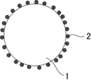
- FIG. 2 is a schematic cross-sectional view of an example of particles of a green phosphor.
- FIG. 3 is a schematic cross-sectional view of another example of particles of a green phosphor.
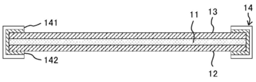
- FIG. 4 is a schematic cross-sectional view showing a configuration example of the end of the phosphor sheet.
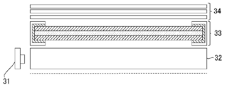
- FIG. 5 is a schematic cross-sectional view showing an edge light type light emitting device.
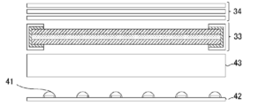
- FIG. 6 is a schematic cross-sectional view showing a direct type light emitting device.
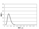
- FIG. 7 is a particle size distribution of neodymium hydroxide used in Examples 1 to 4.
- FIG. 8 shows the emission spectra of Example 1 and Comparative Example 1.
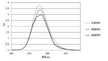
- FIG. 9 shows emission spectra of Examples 2 to 4 and Comparative Example 2.
- FIG. 10 is a diagram showing the chromaticity points of Examples 2 to 4 and Comparative Example 2.
- FIG. 11 is a particle size distribution of neodymium carbonate oxide used in Example 5.
- FIG. 12 shows emission spectra of Examples 2 and 5 and Comparative Example 2.
- FIG. 13 is a graph showing the molar ratio (O / Si) by ICP-AES analysis of the coated phosphors of Reference Examples 1 to 5 and Comparative Reference Example 1.
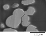
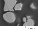
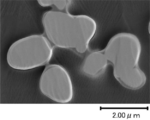
- FIG. 14A is a SEM photograph of the coated phosphor that has not been annealed.
- FIG. 14B is a SEM photograph of the coated phosphor annealed at 600 ° C.
- FIG. 14C is a SEM photograph of the coated phosphor annealed at 700 ° C.
- FIG. 14D is a SEM photograph of the coated phosphor annealed at 800 ° C.
- FIG. 14E is a SEM photograph of the coated phosphor annealed at 900 ° C.
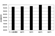
- FIG. 15A is a graph showing the result of the luminous flux maintenance factor at 140 mA in the reliability test.
- FIG. 15B is a graph showing the result of the lumen maintenance factor at the time of storage (non-lighting) in the reliability test.
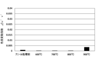
- FIG. 16A is a graph showing the results of the chromaticity variation index at 140 mA in the reliability test.
- FIG. 16B is a graph showing the result of chromaticity variation index at the time of storage (non-lighting) in the reliability test.
- FIG. 17 shows the emission spectra of Examples 6 and 7 and Comparative Example 3.
- the green phosphor of the present invention has at least inorganic phosphor particles and neodymium-containing particles, and further has other components as required.
- the green phosphor has an emission maximum wavelength at 500 nm to 570 nm. This maximum wavelength is also the emission maximum wavelength of the green phosphor.
- a neodymium-containing particle which is a neodymium (Nd) compound
- an emission wavelength to be used instead of suppressing an unnecessary emission peak as in the technique of JP2009-280773A.
- FIG. 1 is the diffuse reflectance spectrum of neodymium hydroxide. As described above, it has an absorption wavelength range in the vicinity of 510 nm to 530 nm, in the vicinity of 580 nm to 610 nm, and the like.
- neodymium hydroxide having the above spectrum is attached to the surface of an inorganic phosphor particle having a light emission maximum wavelength at 535 nm to 570 nm
- the light emission at the foot of the light emission peak is absorbed by neodymium hydroxide, resulting in light emission The peak is narrowed and the color purity is increased.
- the light emission wavelength range absorbed by the neodymium-containing particles may be at a light emission maximum wavelength, if it is slight. In that case, the emission maximum wavelength may shift slightly to the long wavelength side or the short wavelength side.
- the inorganic phosphor particle has an emission maximum wavelength ( ⁇ a) at 500 nm to 570 nm, and the emission maximum wavelength ( ⁇ b) of 500 nm to 570 nm of the green phosphor and the emission maximum wavelength ( ⁇ b)
- the difference ( ⁇ b ⁇ a) with ⁇ a) is preferably more than 0 nm and 10 nm or less, preferably 1 nm or more and 8 nm or less, and particularly preferably 2 nm or more and 5 nm or less.
- the ⁇ a is also the emission maximum wavelength of the inorganic phosphor particles.
- the emission maximum wavelength ( ⁇ b) of the green phosphor is preferably 535 nm to 570 nm, and more preferably 535 to 550 nm.
- the inorganic phosphor particles emit green light.
- the inorganic phosphor particles have, for example, base particles, preferably, a silicon oxide film, and optionally, other components such as zinc oxide.
- the inorganic phosphor particles may be the base particles themselves.
- the inorganic phosphor particles preferably have a light emission maximum wavelength in the range of 500 nm to 570 nm in the light emission peak of itself.
- the emission maximum wavelength ( ⁇ a) of the inorganic phosphor particle is more preferably 535 nm to 570 nm, particularly preferably 535 to 550 nm.
- the base particles include sulfide phosphors. It is preferable that the inorganic phosphor particle has a base particle represented by any one of the following general formula (1) to the following general formula (3).
- Sr 1-x Ga 2 S 4 Eu x ⁇ general formula (1)
- x satisfies 0 ⁇ x ⁇ 1.
- y satisfies 0 ⁇ y ⁇ 1.
- z satisfies 0 ⁇ z ⁇ 1.
- the base particles are preferably ⁇ -type sialon phosphor particles in which Eu is activated, from the viewpoint of obtaining a green phosphor with higher color purity.
- a ⁇ -type sialon phosphor particle is a solid solution of ⁇ -type silicon nitride, in which aluminum (Al) is substituted in solid solution at the Si position of ⁇ -type silicon nitride crystal and oxygen (O) is substituted at nitrogen (N) position. It is melted. Since the unit cell (unit cell) of the ⁇ -type sialon used for the ⁇ -type sialon phosphor particle has atoms of two formula weights, as a general formula of the ⁇ -type sialon, for example, Si 6-z Al z O z N 8 -Z is used. In this general formula, z is more than 0 and less than 4.2.
- ⁇ -type sialon phosphor particles it is preferable that the solid solution range of the ⁇ -type sialon is very wide, and the molar ratio of (Si, Al) / (N, O) is maintained at 3/4.
- a general production method of ⁇ -type sialon is a method of heating by adding silicon oxide and aluminum nitride, or aluminum oxide and aluminum nitride, in addition to silicon nitride.
- ⁇ -SiAlON is a ⁇ -SiAlON that emits green light with a wavelength of 520 nm to 560 nm by being excited with ultraviolet to blue light by incorporating a light emitting element such as rare earth (Eu, Sr, Mn, Ce, etc.) in the crystal structure. It becomes a phosphor. This is preferably used as a green light emitting component of a light emitting body such as a white LED.
- Eu-activated ⁇ -type sialon phosphors which are ⁇ -type sialon phosphors containing europium (Eu 2+ , Eu 3+ ), have narrow emission of blue, green and red because the emission spectrum is very sharp. It is a material suitable for a required image processing display device or a backlight source of a liquid crystal display panel.
- the ⁇ -type sialon phosphor particles in which Eu is activated are represented, for example, by the following general formula (4).
- General formula (4) In the general formula (4), z satisfies 0 ⁇ z ⁇ 4.2.
- the ⁇ -type sialon phosphor particles may be commercially available products.
- Examples of the commercially available product include NIMS Standard Green manufactured by Sialon Corporation.
- the inorganic phosphor particle may have a base particle and a silicon oxide film on the surface of the base particle.
- the neodymium-containing particles are disposed on the surface of the silicon oxide film.
- the above-mentioned inorganic phosphor particles having a base particle and a silicon oxide film on the surface of the base particle may be referred to as "coated phosphor particle”.
- the silicon oxide film covers the base particles of the inorganic phosphor particles. Although it is preferable to completely coat the base particles as the degree of the coating, it is not necessary to completely coat the base particles, as long as the base particles can be coated to such an extent that the effect by the coating can be obtained.
- the silicon oxide film does not have to have a molar ratio of oxygen atoms to silicon atoms (O / Si) of 2.00.
- an average thickness of the said silicon oxide film there is no restriction
- the average thickness can be determined, for example, from the thickness of the silicon oxide film measured at any ten places by observing the cross section of the green phosphor with a scanning or transmission electron microscope.
- the silicon oxide film may contain other components as long as the object of the present invention can be achieved.
- the molar ratio (O / Si) is calculated as the molar ratio (O / Si) of Si to O of silicon oxide in the silicon oxide film. .
- the inventors of the present invention conducted intensive studies to provide coated phosphor particles that are excellent in stability under high temperature and high humidity in the lighted state of the LED.
- the coated phosphor particles obtained by applying heat to the silicon oxide film are excellent in the stability under high temperature and high humidity in the lighting state of the LED. I found it.
- fever was observed, it discovered that the molar ratio (O / Si) of an oxygen atom and a silicon atom was changing. This is considered to be due to the densification of the silicon oxide film.
- the present inventors have determined the molar ratio (O / Si) of oxygen atom to silicon atom of the silicon oxide film in ICP emission spectral analysis. By making 2.70 or less, it discovered that the covering fluorescent substance particle which is excellent in stability under the high temperature, high humidity in the LED lighting state was obtained.
- the molar ratio (O / Si) of the oxygen atom of the said silicon oxide film and silicon atom in ICP emission spectral analysis about the said green fluorescent substance is 2.60 or less.
- the molar ratio (O / Si) exceeds 2.60, the stability under high temperature and high humidity in the lighted state of the LED is not improved.
- limiting in particular as a lower limit of the said molar ratio (O / Si) According to the objective, it can select suitably, For example, even if the said molar ratio (O / Si) is 2.00 or more It may be 2.30 or more.
- the molar ratio (O / Si) is preferably 2.00 or more and 2.60 or less, more preferably 2.30 or more and 2.55 or less, and particularly preferably 2.30 or more and 2.45 or less.
- Examples of the method of adjusting the molar ratio (O / Si) include a heating step in a method of producing coated phosphor particles described later.
- the molar ratio (O / Si) can be determined by ICP emission spectroscopy.
- a solution in which the whole green phosphor is dissolved may be used as a measurement sample, or the silicon oxide film is isolated from the green phosphor and the silicon oxide is isolated.
- a solution in which the film is dissolved may be used as a measurement sample.
- a solution in which the whole green phosphor is dissolved can be used as a measurement sample by using an alkaline melting method (JIS R 930 1-3-3) using sodium carbonate.
- particle diameter D90 of the said inorganic fluorescent substance particle there is no restriction
- D90 represents the value of the particle diameter when the integrated value is 90% in the particle size distribution of particles.
- the green phosphor may contain zinc oxide.
- the zinc oxide is, for example, disposed on the outermost surface of the inorganic phosphor particles.
- the zinc oxide is, for example, disposed in the form of a film on the outermost surface of the inorganic phosphor particles.
- the zinc oxide can adsorb a sulfur-based gas (e.g., hydrogen sulfide) generated from the sulfide-based phosphor when the inorganic phosphor particles are a sulfide-based phosphor, and as a result, the sulfur-based gas Corrosion of electrodes etc can be prevented.
- a sulfur-based gas e.g., hydrogen sulfide
- the method for producing the coated phosphor particles at least includes a coating step, preferably includes a heating step, and further includes other steps as necessary.
- the coating step is not particularly limited as long as it is a step of forming a silicon oxide film on the surface of base particles and obtaining coated phosphor particles, and can be appropriately selected according to the purpose.
- These treatments may be so-called hydrolysis of alkoxysilane (sol gel method).
- an alkoxysilane etc. are mentioned, for example.
- the alkoxysilane can be selected, for example, from ethoxide, methoxide, isopropoxide and the like, and examples thereof include tetraethoxysilane and tetramethoxysilane.
- the alkoxysilane may be an alkoxysilane oligomer such as polyethyl silicate or a hydrolytic condensate.
- the alkoxysilane may be a silane coupling agent having an alkyl group, an amino group, a mercapto group or the like which does not contribute to the sol-gel reaction, such as an alkylalkoxysilane.
- the liquid may contain a solvent.
- a solvent for example, water, an organic solvent or the like can be used.
- organic solvent for example, alcohol, ether, ketone, polyhydric alcohol and the like can be used.
- alcohol methanol, ethanol, a propanol, a pentanol etc. can be used, for example.
- ethylene glycol, propylene glycol, diethylene glycol and the like can be used as the polyhydric alcohol.
- the solvent may be a combination of two or more.
- the formation of the silicon oxide film in the coating step may be performed using a catalyst.
- the catalyst is for initiating the hydrolysis or polycondensation reaction of the alkoxysilane, and for example, an acidic catalyst or a basic catalyst can be used.
- the acidic catalyst include hydrochloric acid, sulfuric acid, boric acid, nitric acid, perchloric acid, tetrafluoroboric acid, hexafluoroarsenic acid, hydrobromic acid, acetic acid, oxalic acid, methanesulfonic acid and the like.
- the basic catalyst include hydroxides of alkali metals such as sodium hydroxide, ammonia, and the like.
- two or more of these acidic catalysts and basic catalysts may be used in combination.
- the heating step is not particularly limited as long as it is a step of heating the coated phosphor particles at a temperature exceeding the formation temperature of the silicon oxide film and in an inert atmosphere, and may be appropriately selected according to the purpose. Can.
- the formation temperature of the silicon oxide film may be, for example, 300 ° C. or less, or 100 ° C. to 250 ° C.
- the lower limit value of the heating temperature in the heating step is not particularly limited as long as the temperature exceeds the formation temperature of the silicon oxide film, and can be appropriately selected according to the purpose.
- the temperature of the heating May be 500 ° C. or higher, or 550 ° C. or higher.
- the temperature of the said heating is 1,200 degrees C or less from the point which prevents the integration of the said silicon oxide film. Is preferred, less than 1,000.degree. C. is more preferred, and less than 900.degree. C. is particularly preferred.
- the silicon oxide film is densified, and as a result, coated phosphor particles excellent in stability under high temperature and high humidity in the lighted state of the LED are obtained. Conceivable.
- the neodymium-containing particles are attached to the surface of the inorganic phosphor particles.
- the neodymium-containing particles are not particularly limited as long as they contain neodymium, and can be appropriately selected according to the purpose.
- neodymium hydroxide eg, Nd (OH) 3 , NdO 2 H, etc.
- Nd (OH) 3 , NdO 2 H, etc. particles
- carbonate Neodymium oxide (Nd 2 O 2 CO 3 ) particles
- neodymium aluminate particles neodymium silicate particles
- neodymium vanadate (NdVO 4 ) particles neodymium tungstate (Nd 2 W 3 O 12)
- Nd 2 W 3 O 12 neodymium tungstate
- neodymium aluminate in the neodymium aluminate particles examples include NdAlO 3 , NdAl 11 O 8 , NdAl 11 O 18 , Nd 1.65 Al 23.43 O 38 , Nd 4 Al 2 O 9 and the like.
- neodymium silicate in the neodymium silicate particle for example, NdSiO 5 , Nd 2 SiO 5 , Nd 2 Si 2 O 7 , Nd 2 Si 3 O 9 , Nd 2 Si 3 O 12 , Nd 4 Si 3 O 12 , Nd 9 .33 (SiO 4 ) 6 O 2 and the like.
- the neodymium-containing particles contain at least one of neodymium hydroxide, neodymium carbonate oxide, and neodymium oxide in that the main peak in the green phosphor is easily narrowed.
- grains there is no restriction
- the average particle diameter can be measured, for example, by a dynamic light scattering type particle size distribution analyzer (eg, LB-550 manufactured by HORIBA).
- an average particle diameter of the said green fluorescent substance there is no restriction
- the average particle size can be measured by a laser diffraction type particle size distribution analyzer (for example, LA-960 manufactured by HORIBA).
- particle diameter D90 of the said green fluorescent substance there is no restriction
- D90 represents the value of the particle diameter when the integrated value is 90% in the particle size distribution of particles.
- Narrowing of a luminescence peak may not be enough if there are few, Moreover If it is too large, the decrease in emission peak intensity may be large, so 1% by mass to 60% by mass is preferable, and 5% by mass to 55% by mass is more preferable with respect to the content of the inorganic phosphor particles in the green phosphor. Preferably, 10% by mass to 50% by mass is particularly preferable.
- FIG. 2 is a schematic cross-sectional view of an example of particles of a green phosphor.
- the particles of the green phosphor shown in FIG. 2 have inorganic phosphor particles 1 and neodymium-containing particles 2 on the surface of the inorganic phosphor particles 1.
- FIG. 3 is a schematic cross-sectional view of another example of particles of a green phosphor.
- the green phosphor particles shown in FIG. 3 have inorganic phosphor particles and neodymium-containing particles 2 on the surface of the inorganic phosphor particles.
- the inorganic phosphor particles have a base particle 1a and a silicon oxide film 1b on the surface of the base particle 1a.
- the neodymium-containing particles 2 adhere to the surface of the silicon oxide film 1 b.
- the phosphor sheet of the present invention contains at least the green phosphor of the present invention, preferably contains a resin, and further contains other components as required.
- the phosphor sheet is obtained, for example, by applying a phosphor-containing resin composition (so-called phosphor paint) containing the green phosphor and a resin to a transparent substrate.
- a phosphor-containing resin composition so-called phosphor paint
- containing the green phosphor and a resin there is no restriction
- limiting in particular as content of the said green fluorescent substance in the said fluorescent substance sheet According to the objective, it can select suitably.
- thermoplastic resin a thermoplastic resin, a photocurable resin, etc. are mentioned.
- thermoplastic resin There is no restriction
- the hydrogenated styrene copolymer is not particularly limited and may be appropriately selected according to the purpose. Examples thereof include hydrogenated products of styrene-ethylene-butylene-styrene block copolymer.
- the proportion of the styrene unit in the styrene-ethylene-butylene-styrene block copolymer is not particularly limited and may be appropriately selected according to the purpose, but it is preferably 20 mol% to 30 mol%. Moreover, there is no restriction
- MMA methyl methacrylate
- BA butyl acrylate
- the photocurable resin is produced using a photocurable compound.
- photocurable (meth) acrylates such as urethane (meth) acrylate, etc.
- the urethane (meth) acrylate is, for example, a product containing an isocyanate group obtained by reacting a polyol and a polyisocyanate (for example, isophorone diisocyanate etc.) as a hydroxyalkyl (meth) acrylate (for example, Esterified with hydroxypropyl acrylate etc.).
- the content of the urethane (meth) acrylate in 100 parts by mass of the photocurable (meth) acrylate is not particularly limited and may be appropriately selected depending on the purpose, but 10 parts by mass or more is preferable.
- the resin composition containing the said resin contains either a polyolefin copolymer component or a photocurable (meth) acrylic resin component.
- a polyolefin copolymer component contains either a polyolefin copolymer component or a photocurable (meth) acrylic resin component.
- a polyolefin copolymer component contains either a polyolefin copolymer component or a photocurable (meth) acrylic resin component.
- a polyolefin copolymer there is no restriction
- styrene-type copolymer there is no restriction
- the content ratio of styrene units in the hydrogenated styrene copolymer tends to decrease mechanical strength if it is too low, and tends to become brittle if it is too high, so 10% by mass to 70% by mass is preferable. And 20% by mass to 30% by mass are more preferable. If the hydrogenation rate of the hydrogenated styrenic copolymer is too low, the weather resistance tends to deteriorate, and is preferably 50% or more, more preferably 95% or more.
- photocurable acrylate resin component there is no restriction
- particles diffusion material
- the excitation light can be diffused (scattered) by the particles, so that the absorption of the excitation light into the green phosphor can be enhanced.
- the amount of addition of the phosphor can be reduced.
- the particles (diffusing material) include silicone particles, silica particles, resin particles, composite particles of melamine and silica, and the like.
- the resin of the resin particles include melamine, crosslinked poly (methyl methacrylate), crosslinked polystyrene and the like.
- the particles include, for example, silicone powder KMP series manufactured by Shin-Etsu Chemical Co., Ltd., opto-beads manufactured by Nissan Chemical Industries, Ltd., techpolymer MBX series manufactured by Sekisui Plastics Co., Ltd., SBX Commercially available products such as series can be mentioned.
- thermoplastic resin film a thermosetting resin film, a photocurable resin film, etc. are mentioned (Unexamined-Japanese-Patent No. 2011-13567) Gazette, JP 2013-32515 A, JP 2015-967 A)).
- polyester films such as a polyethylene terephthalate (PET) film, a polyethylene naphthalate (PEN) film; Polyamide film; Polysulfone film; Triacetyl cellulose film; Polyolefin film; Polycarbonate (PC) film; Polystyrene (PS) film; Polyethersulfone (PES) film; Cyclic amorphous polyolefin film; Multifunctional acrylate film; Polyfunctional polyolefin film; Unsaturated polyester film; epoxy resin film; fluorine resin film such as PVDF, FEP, PFA, etc .; These may be used alone or in combination of two or more.
- PET polyethylene terephthalate
- PEN polyethylene naphthalate
- Polyamide film Polysulfone film
- Triacetyl cellulose film Polyolefin film
- PC Polycarbonate
- PS Polystyrene
- PS Polyethersulfone
- PET polyethylene terephthalate
- PEN polyethylene naphthalate
- the surface of such a film may be subjected to a corona discharge treatment, a silane coupling agent treatment, etc., if necessary.
- the thickness of the transparent substrate is not particularly limited and may be appropriately selected according to the purpose, but 10 ⁇ m to 100 ⁇ m is preferable.
- the transparent substrate is preferably a water vapor barrier film in that the hydrolysis of the inorganic phosphor particles can be reduced.
- the water vapor barrier film is a gas barrier film in which a metal oxide thin film such as aluminum oxide, magnesium oxide or silicon oxide is formed on the surface of a plastic substrate such as PET (polyethylene terephthalate) or a film. Also, a multilayer structure such as PET / SiO x / PET may be used.
- the water vapor permeability of the barrier film is not particularly limited and may be appropriately selected depending on the purpose, 0.05 g / m 2 / day ⁇ 5g / m 2 / day about (e.g., 0.1 g / Relatively low barrier performance on the order of m 2 / day) is preferred. Within such a range, penetration of water vapor can be suppressed to protect the phosphor sheet from water vapor.
- FIG. 4 is a schematic cross-sectional view showing a configuration example of the end of the phosphor sheet.
- the phosphor layer 11 is sandwiched between the first water vapor barrier film 12 and the second water vapor barrier film 13.
- the phosphor layer 11 is composed of the green phosphor of the present invention and a resin, and the green phosphor is dispersed in the resin.
- the cover member 14 having an end portion of the first water vapor barrier film 12 and an end portion of the second water vapor barrier film 13 has a water vapor transmission rate of 1 g / m 2 / day or less. Is preferably sealed.
- the cover member 14 it is possible to use a pressure-sensitive adhesive tape in which a pressure-sensitive adhesive 142 is applied to a substrate 141 having a water vapor transmission rate of 1 g / m 2 / day or less.
- the base material 141 metal foil such as aluminum foil or the like and the water vapor barrier films 12, 13 can be used.
- aluminum foil may use either glossy white aluminum or non-lustrous black aluminum, it is preferable to use white aluminum when a good color tone at the end of the phosphor sheet is required.
- the width W of the cover member 14 to be attached onto the water vapor barrier film is preferably 1 mm to 10 mm, and more preferably 1 mm to 5 mm from the viewpoint of water vapor barrier properties and strength. According to the cover member 14 having such a configuration, it is possible to prevent water vapor from entering the phosphor layer from the end of the water vapor barrier film, and to prevent deterioration of the phosphor in the phosphor layer. .
- the light emitting device of the present invention has at least the phosphor sheet of the present invention, and further has other members as required.
- FIG. 5 is a schematic cross-sectional view showing an edge light type light emitting device.
- the light emitting device diffuses the blue light of the blue LED 31 and the blue light of the blue LED 31 incident from the side, and a light guide plate 32 that emits uniform light on the surface, and a phosphor that obtains white light from blue light A so-called "edge light type backlight" including the sheet 33 and the optical film 34 is configured.
- the blue LED 31 constitutes a so-called "LED package” having an InGaN-based LED chip as a blue light emitting element.
- the light guide plate 32 uniformly emits light from the end face of a transparent substrate such as an acrylic plate.
- the phosphor sheet 33 is, for example, a phosphor sheet shown in FIG.
- the powder of the phosphor contained in the phosphor sheet 33 has an average particle diameter of several ⁇ m to several tens of ⁇ m. Thereby, the light scattering effect of the phosphor sheet 33 can be improved.
- the optical film 34 is made of, for example, a reflective polarizing film, a diffusion film or the like for improving the visibility of the liquid crystal display device.
- FIG. 6 is a schematic cross-sectional view showing a direct type light emitting device.
- a substrate 42 on which blue LEDs 41 are two-dimensionally arranged, a diffusion plate 43 for diffusing the blue light of the blue LEDs 41, and a substrate 42 are disposed apart from A so-called "direct-type backlight" is provided, which includes a phosphor sheet 33 for obtaining the light intensity and an optical film 34.
- the blue LED 41 constitutes a so-called "LED package” having, for example, an InGaN-based LED chip as a blue light emitting element.
- the substrate 42 is made of a glass cloth base material using a resin such as phenol, epoxy, polyimide, etc.
- blue LEDs 41 are equally spaced at a predetermined pitch, and two corresponding to the entire surface of the phosphor sheet 33. Placed in a dimension.
- the mounting surface of the blue LED 41 on the substrate 42 may be subjected to a reflection process as necessary.
- the substrate 42 and the phosphor sheet 33 are spaced apart by about 10 to 50 mm, and the light emitting device constitutes a so-called "remote phosphor structure".
- the gap between the substrate 42 and the phosphor sheet 33 is held by a plurality of support columns and reflectors, and the support columns and reflectors are provided so as to surround the space formed by the substrate 42 and the phosphor sheet 33 in four directions. .
- the diffusion plate 43 diffuses the emitted light from the blue LED 41 in such a wide range that the shape of the light source can not be seen, and has a total light transmittance of, for example, 20% or more and 80% or less.
- the present invention is not limited to the above-described embodiment, and it goes without saying that various updates can be added without departing from the scope of the present invention.
- the example which applied the light-emitting device to the backlight light source for display apparatuses was shown in above-mentioned embodiment, you may apply to the light source for illumination.
- the optical film 34 is often unnecessary.
- the phosphor-containing resin may have not only a flat sheet shape but also a three-dimensional shape such as a cup shape.
- a powdered gallium compound was added to a solution containing a europium compound and a strontium compound, and a sulfite was dropped to obtain a powder containing Sr, Eu, and Ga. Specifically, the following method was implemented.
- Ga 2 O 3 (purity 7N), Sr (NO 3 ) 2 (purity 3N) and Eu 2 O 3 (purity 3N) which are reagents manufactured by High Purity Chemical Laboratory Ltd., and Kanto Chemical Co., Ltd.
- a company-made nitric acid aqueous solution (concentration 20%) and ammonium sulfite monohydrate were prepared.
- Eu 2 O 3 was added to the aqueous nitric acid solution and stirred at 80 ° C. to dissolve Eu 2 O 3 in the aqueous nitric acid solution, and then the solvent was evaporated to obtain Eu (NO 3 ) 3 .
- the europium compound [Eu (NO 3 ) 3 ] and the strontium compound [Sr (NO 3 ) 2 ] were added to 500 mL of pure water and stirred.
- a solution containing a europium compound and a strontium compound could be obtained.
- the value of x can be changed by changing the ratio of Eu (NO 3 ) 3 to Sr (NO 3 ) 2 , thereby adjusting the concentration of Eu as the luminescence center.
- a powdery gallium compound specifically, powdery Ga 2 O 3
- a sulfite was dropped into the solution while stirring.
- a solution containing 1.5 times the number of moles of ammonium sulfite as the total number of moles of Sr and Eu was dropped to obtain a precipitate / precipitate.
- the precipitates and precipitates contain Sr, Eu and Ga, and more specifically, a mixture of europium sulphite sulfite powder and gallium oxide powder. Then, the precipitate is washed with pure water until the conductivity is 0.1 mS / cm or less, filtered, and dried at 120 ° C.
- the powder mixture was then fired in an electric furnace.
- the firing conditions were as follows. That is, the temperature was raised to 925 ° C. in 1.5 hours, then held at 925 ° C. for 1.5 hours, and then lowered to room temperature in 2 hours.
- Hydrogen sulfide was flowed into the electric furnace at a rate of 0.5 L / min during firing. After that, passing through a mesh having a nominal opening of 25 ⁇ m, a sulfide green phosphor (SrGa 2 S 4 : Eu) consisting of Sr 1 -xGa 2 S 4 : Eu x (x is about 0.1) was obtained.
- the average particle size of the obtained sulfide green phosphor (SrGa 2 S 4 : Eu) was about 4 ⁇ m.
- Example 1 ⁇ Adhesion of neodymium-containing particles>
- neodymium hydroxide Na (OH) 3 , manufactured by Dainichiseika Kogyo Co., Ltd., average particle diameter: 100 nm
- the particle size distribution of neodymium hydroxide used is shown in FIG. 100 parts by mass of the sulfide green phosphor produced in Production Example 1 and 20 parts by mass of neodymium hydroxide were mixed and stirred in the presence of a solvent (isopropyl alcohol) for 1 hour, and then filtered and washed. Thereafter, it was dried at 80 ° C. for 2 hours to obtain a phosphor.
- a solvent isopropyl alcohol
- neodymium-containing particles 2 are present on the surface of the inorganic phosphor particles 1.
- the entire amount of neodymium hydroxide could be attached to the surface of the sulfide green phosphor.
- the emission characteristics are evaluated by light emission (PL) spectrum measurement. Specifically, a phosphor powder is filled in a dedicated cell, and blue excitation light with a wavelength of 450 nm is irradiated, and a spectrofluorimeter FP-6500 (JASCO Corporation PL spectrum was measured using The emission peak wavelength (nm), the emission peak intensity (relative value), and the emission half width (nm) of the peak in the obtained PL spectrum were measured. The results are shown in Table 1.
- the relative value based on the PL spectrum data of a general YAG phosphor P46-Y3 material (reference example in Table 1) manufactured by Kasei Optronics (now Mitsubishi Chemical Co., Ltd.) was determined. . Further, the conversion efficiency of the phosphor includes sample absorption rate (%) which is the efficiency of absorbing the excitation light, internal quantum efficiency (%) which is the efficiency of converting the absorbed excitation light into fluorescence, and their product An external quantum efficiency (%) was calculated. The internal quantum efficiency was determined by using the quantum efficiency calculation software attached to the spectrofluorimeter.
- the emission spectra of Example 1 and Comparative Example 1 are shown in FIG.
- the content of the neodymium-containing particles is mass% relative to the content of the phosphor particles to be attached.
- x represents x value of ClE chromaticity.
- y represents y value of ClE chromaticity.
- Y represents luminance.
- FWHM represents the full width at half maximum of emission.
- Example 1 As shown in FIG. 8, the emission spectrum of Example 1 is narrower than that of Comparative Example 1. In addition, although the fall of the light emission intensity of a peak top and the fall of a quantum efficiency were seen compared with the comparative example 1 of Example 1, the point of having narrowed it is the advantage over the demerit.
- Example 2 A phosphor was obtained in the same manner as in Example 1, except that the sulfide green phosphor produced in Production Example 1 was replaced with the coated phosphor subjected to the annealing treatment produced in Production Example 2 in Example 1. .
- neodymium-containing particles 2 neodymium hydroxide
- the luminescent characteristics were evaluated in the same manner as in Example 1. The results are shown in Table 2.
- the emission spectrum is shown in FIG.
- Example 3 A phosphor was obtained in the same manner as in Example 2 except that the amount of neodymium hydroxide used in Example 2 was changed from 20 parts by mass to 30 parts by mass. The luminescent characteristics were evaluated in the same manner as in Example 1. The results are shown in Table 2. In addition, the emission spectrum is shown in FIG.
- Example 4 A phosphor was obtained in the same manner as in Example 2 except that the amount of neodymium hydroxide used in Example 2 was changed from 20 parts by mass to 40 parts by mass. The luminescent characteristics were evaluated in the same manner as in Example 1. The results are shown in Table 2. In addition, the emission spectrum is shown in FIG.
- Comparative example 2 The coated phosphor subjected to the annealing treatment prepared in Production Example 2 was used as the phosphor of Comparative Example 2. The luminescent characteristics were evaluated in the same manner as in Example 1. The results are shown in Table 2. In addition, the emission spectrum is shown in FIG.
- the emission spectrums of Examples 2 to 4 are narrower than those of Comparative Example 2.
- the peak top emission intensity and the quantum efficiency were reduced as compared with Comparative Example 2, the point of narrowing is an advantage over the disadvantage.
- Example 5 In Example 2, neodymium hydroxide (manufactured by Dainichi Seika Kogyo Co., Ltd., average particle diameter 100 nm) was changed to neodymium carbonate oxide (Nd 2 O 2 CO 3 , manufactured by Dainichi Seika Kogyo Co., Ltd., average particle diameter 3 ⁇ m) A phosphor was obtained in the same manner as in Example 2 except for the above. The particle size distribution of the neodymium carbonate oxide used is shown in FIG. The luminescent characteristics were evaluated in the same manner as in Example 1. The results are shown in Table 3. In addition, the emission spectrum is shown in FIG.
- Example 5 As shown in FIG. 12, the emission spectrum of Example 5 is narrower than that of Comparative Example 2. In addition, although the fall of the luminescence intensity of a peak top and the fall of a quantum efficiency were seen compared with the comparative example 2 of Example 5, the point of having narrowed it is the advantage over the demerit.
- ⁇ O / Si amount> For the coated phosphors of Examples 2 to 5 and Comparative Example 2, the amount of O / Si was measured. The measurement was performed by the following method. 0.05 g of the coated phosphor was weighed into a platinum crucible with 0.375 g of sodium carbonate and 0.125 g of boric acid. After heating and melting at 900 ° C., it was cooled. 5 ml of 50% hydrochloric acid and 2 ml of hydrogen peroxide were added, and the resulting precipitate was recovered. This was dissolved in a 10% nitric acid aqueous solution to obtain a solution. ICP emission spectral analysis (ICP-AES) was performed on the obtained solution.
- ICP emission spectral analysis ICP emission spectral analysis
- the molar ratio (O / Si) of O to Si in the coating layer was determined from the ratio of the peak intensity of each of the obtained O (oxygen atom) and Si (silicon atom). The results are shown in Table 4.
- requiring the said molar ratio (O / Si) it is necessary to deduct the oxygen of the neodymium hydroxide or the neodymium carbonated addition part. Therefore, neodymium hydroxide or a neodymium carbonate content oxygen value was subtracted from the sample as a blank value after measuring Nd and O by ICP of neodymium hydroxide or neodymium carbonate oxide alone.
- the coated phosphor before annealing treatment obtained in Production Example 2 was subjected to an inert high temperature annealing treatment under the following conditions using an atmosphere baking furnace.
- Comparative Reference Example 1 The coated phosphor before annealing treatment obtained in Production Example 2 was used as the coated phosphor of Comparative Reference Example 1.
- the molar ratio (O / Si) of O to Si was 2.76, while in the reference examples 1 to 5 in which the annealing treatment was conducted, the molar ratio (O / Si) decreased to 2.60 or less.
- FIGS. 14A-14E SEM (scanning electron microscope) observation of the coated phosphor was performed. The results are shown in FIGS. 14A-14E.
- the coated phosphor used here is a coated phosphor obtained by increasing the average thickness of the silicon oxide film to 70 nm in Production Example 2.
- a coated phosphor having a thick silicon oxide film was produced in Production Example 2 by increasing the concentration of tetraethoxysilane.
- FIG. 14A is a SEM photograph of the coated phosphor that has not been annealed.
- FIG. 14B is a SEM photograph of the coated phosphor annealed at 600 ° C.
- FIG. 14C is a SEM photograph of the coated phosphor annealed at 700 ° C.
- FIG. 14D is a SEM photograph of the coated phosphor annealed at 800 ° C.
- FIG. 14E is a SEM photograph of the coated phosphor annealed at 900 ° C.
- Annealing was performed on the coated phosphor before the annealing treatment obtained in Production Example 2 in the same manner as in Reference Examples 1 to 5.
- the annealing temperatures were 600 ° C., 700 ° C., 800 ° C., and 900 ° C.
- the coated phosphor after the annealing treatment and the coated phosphor of Comparative Reference Example 1 were dispersed in a resin (methyl-based KER-2910) in an LED package. The resin was then cured to obtain an LED package containing the coated phosphor. A lighting / storage test was conducted on this LED package. The test conditions were such that the LED was continuously energized at 140 mA in an environment of 70 ° C.
- the initial luminous flux maintenance factor (lm%) and the chromaticity fluctuation ( ⁇ u′v ′) at this time were confirmed.
- the initial luminous flux maintenance factor (lm%) and the chromaticity fluctuation ( ⁇ u'v ') were also confirmed when the LED was stored for 504 hours without power (non-lighting) under an environment of 70 ° C. and 85% RH. The details of the measurement are as follows.
- Tables 9-1 and 9-2 and FIGS. 15A and 15B show the results at 140 mA energization.
- Table 9-2 and FIG. 15B show the results when stored (unlit).
- Tables 10-1 and 10-2 and FIGS. 16A and 16B The results of the chromaticity variation index ( ⁇ u'v ') are shown in Tables 10-1 and 10-2 and FIGS. 16A and 16B.
- Table 10-1 and FIG. 16A show the results at 140 mA energization.
- Table 10-2 and FIG. 16B show the results when stored (unlit).
- Example 6 ⁇ Material> As the inorganic phosphor particles, Eu 2+ activated ⁇ -type sialon phosphor (NIMS Standard Green manufactured by Sialon Co., Ltd.) was used. As the neodymium-containing particles, neodymium hydroxide (Nd (OH) 3 , manufactured by Dainichiseika Kogyo Co., Ltd., average particle diameter: 100 nm) was used. As a dispersion solvent, IPA [isopropyl alcohol (2-propanol)] manufactured by Daishin Chemical Co., Ltd. was used.
- IPA isopropyl alcohol (2-propanol)
- ⁇ Adhesion of neodymium-containing particles > 100 parts by mass of inorganic phosphor particles (Eu 2+ activated ⁇ -type sialon phosphor) and 20 parts by mass of neodymium hydroxide [Nd (OH) 3 ] in the presence of a solvent (IPA) for 1 hour, and then stirring Filtered and washed. Thereafter, the resultant was dried at 80 ° C. for 2 hours to obtain a green phosphor to which neodymium-containing particles are attached.
- inorganic phosphor particles Eu 2+ activated ⁇ -type sialon phosphor
- Nd (OH) 3 neodymium hydroxide
- Example 7 In Example 6, 20 parts by weight neodymium hydroxide [Nd (OH) 3], was changed to 40 parts by weight neodymium hydroxide [Nd (OH) 3], in the same manner as in Example 6, neodymium-containing particles The obtained green phosphor was attached.
- FIG. 17 shows the emission spectrum of the fabricated sample normalized by the peak intensity. From the emission spectrum of FIG. 17, it can be clearly seen that the half widths of Examples 6 and 7 are narrower than those of Comparative Example 3. The half of the vertical axis corresponds to half width.
- Example 6 is still substantially the same as Comparative Example 3 in Example 6, but in Example 7 where the width is further narrowed, the vicinity of 530 nm is further shaved off and the half width is narrowed I understand that However, since the long wave side is not scraped further than this, it is considered that further narrowing of the half width is difficult even if neodymium-containing particles are further added.
- the green phosphor of the present invention can be suitably used for a white LED since it is excellent in color purity.
Landscapes
- Chemical & Material Sciences (AREA)
- Engineering & Computer Science (AREA)
- Materials Engineering (AREA)
- Organic Chemistry (AREA)
- Inorganic Chemistry (AREA)
- Luminescent Compositions (AREA)
- Led Device Packages (AREA)
Abstract
Un luminophore vert ayant une longueur d'onde maximale d'émission à 500-570 nm, le luminophore vert contenant des particules de phosphore inorganique et des particules contenant du néodyme fixées à la surface des particules de phosphore inorganique.
Priority Applications (5)
| Application Number | Priority Date | Filing Date | Title |
|---|---|---|---|
| EP18882324.9A EP3719100B1 (fr) | 2017-11-30 | 2018-11-22 | Luminophore vert, feuille de phosphore et dispositif électroluminescent |
| KR1020207016656A KR102648452B1 (ko) | 2017-11-30 | 2018-11-22 | 녹색 형광체, 형광체 시트 및 발광 장치 |
| CN201880076344.7A CN111417699A (zh) | 2017-11-30 | 2018-11-22 | 绿色荧光体、荧光体片和发光装置 |
| US16/764,961 US11312903B2 (en) | 2017-11-30 | 2018-11-22 | Green phosphor, phosphor sheet, and light-emitting device |
| US17/573,848 US11760927B2 (en) | 2017-11-30 | 2022-01-12 | Green phosphor, phosphor sheet, and light-emitting device |
Applications Claiming Priority (6)
| Application Number | Priority Date | Filing Date | Title |
|---|---|---|---|
| JP2017230487 | 2017-11-30 | ||
| JP2017-230487 | 2017-11-30 | ||
| JP2018-200520 | 2018-10-25 | ||
| JP2018200520 | 2018-10-25 | ||
| JP2018-217893 | 2018-11-21 | ||
| JP2018217893A JP6949806B2 (ja) | 2017-11-30 | 2018-11-21 | 緑色蛍光体、蛍光体シート、及び発光装置 |
Related Child Applications (2)
| Application Number | Title | Priority Date | Filing Date |
|---|---|---|---|
| US16/764,961 A-371-Of-International US11312903B2 (en) | 2017-11-30 | 2018-11-22 | Green phosphor, phosphor sheet, and light-emitting device |
| US17/573,848 Division US11760927B2 (en) | 2017-11-30 | 2022-01-12 | Green phosphor, phosphor sheet, and light-emitting device |
Publications (1)
| Publication Number | Publication Date |
|---|---|
| WO2019107285A1 true WO2019107285A1 (fr) | 2019-06-06 |
Family
ID=66665720
Family Applications (1)
| Application Number | Title | Priority Date | Filing Date |
|---|---|---|---|
| PCT/JP2018/043273 Ceased WO2019107285A1 (fr) | 2017-11-30 | 2018-11-22 | Luminophore vert, feuille de phosphore et dispositif électroluminescent |
Country Status (4)
| Country | Link |
|---|---|
| US (2) | US11312903B2 (fr) |
| JP (1) | JP7245879B2 (fr) |
| TW (1) | TWI831758B (fr) |
| WO (1) | WO2019107285A1 (fr) |
Cited By (1)
| Publication number | Priority date | Publication date | Assignee | Title |
|---|---|---|---|---|
| WO2024071305A1 (fr) * | 2022-09-30 | 2024-04-04 | 三井金属鉱業株式会社 | Poudre de phosphore, composition contenant du phosphore, phosphore, élément électroluminescent et dispositif électroluminescent |
Families Citing this family (1)
| Publication number | Priority date | Publication date | Assignee | Title |
|---|---|---|---|---|
| WO2019107285A1 (fr) * | 2017-11-30 | 2019-06-06 | デクセリアルズ株式会社 | Luminophore vert, feuille de phosphore et dispositif électroluminescent |
Citations (8)
| Publication number | Priority date | Publication date | Assignee | Title |
|---|---|---|---|---|
| JP4343267B1 (ja) | 2008-09-11 | 2009-10-14 | 三井金属鉱業株式会社 | 緑色蛍光体 |
| JP2009280773A (ja) | 2008-05-26 | 2009-12-03 | Nemoto & Co Ltd | 蛍光体 |
| JP2011013567A (ja) | 2009-07-03 | 2011-01-20 | Sony Corp | 色変換部材および表示装置 |
| JP4708507B2 (ja) | 2009-09-18 | 2011-06-22 | 三井金属鉱業株式会社 | 蛍光体 |
| JP2013032515A (ja) | 2011-07-05 | 2013-02-14 | Dexerials Corp | 蛍光体シート形成用樹脂組成物 |
| JP2015000967A (ja) | 2013-06-18 | 2015-01-05 | デクセリアルズ株式会社 | 蛍光体シート |
| JP2015211150A (ja) * | 2014-04-28 | 2015-11-24 | パナソニックIpマネジメント株式会社 | 波長変換部材及びこれを用いた照明装置 |
| JP2017186459A (ja) * | 2016-04-06 | 2017-10-12 | 宇部興産株式会社 | 窒化物蛍光体粉末およびその製造方法 |
Family Cites Families (12)
| Publication number | Priority date | Publication date | Assignee | Title |
|---|---|---|---|---|
| JPS478507Y1 (fr) | 1967-12-22 | 1972-04-01 | ||
| JPS478507U (fr) | 1971-02-20 | 1972-10-02 | ||
| KR20080009416A (ko) | 2006-07-24 | 2008-01-29 | 삼성에스디아이 주식회사 | 플라즈마 디스플레이 패널용 적색 형광체 및 이를 이용한플라즈마 디스플레이 패널 |
| KR101366491B1 (ko) * | 2007-08-22 | 2014-02-24 | 삼성전자주식회사 | 금속 하이드록시 탄산염 나노 입자가 코팅된 형광체 및그의 제조방법 |
| KR101213298B1 (ko) * | 2007-10-10 | 2012-12-18 | 우베 고산 가부시키가이샤 | β-사이알론 형광체 분말 및 그 제조 방법 |
| US8147717B2 (en) | 2008-09-11 | 2012-04-03 | Mitsui Mining & Smelting Co., Ltd. | Green emitting phosphor |
| JP2012199288A (ja) | 2011-03-18 | 2012-10-18 | Panasonic Corp | バックライト装置および液晶ディスプレイ装置 |
| CN102660281B (zh) | 2012-05-28 | 2014-12-31 | 北京晶创达科技有限公司 | 一种二氧化硅包覆的橙红色荧光粉及其制备方法 |
| JP6038524B2 (ja) * | 2012-07-25 | 2016-12-07 | デクセリアルズ株式会社 | 蛍光体シート |
| JP6365159B2 (ja) * | 2014-09-16 | 2018-08-01 | 日亜化学工業株式会社 | 発光装置 |
| WO2019107285A1 (fr) * | 2017-11-30 | 2019-06-06 | デクセリアルズ株式会社 | Luminophore vert, feuille de phosphore et dispositif électroluminescent |
| JP6949806B2 (ja) * | 2017-11-30 | 2021-10-13 | デクセリアルズ株式会社 | 緑色蛍光体、蛍光体シート、及び発光装置 |
-
2018
- 2018-11-22 WO PCT/JP2018/043273 patent/WO2019107285A1/fr not_active Ceased
- 2018-11-22 US US16/764,961 patent/US11312903B2/en active Active
- 2018-11-26 TW TW107142040A patent/TWI831758B/zh active
-
2021
- 2021-08-18 JP JP2021133242A patent/JP7245879B2/ja active Active
-
2022
- 2022-01-12 US US17/573,848 patent/US11760927B2/en active Active
Patent Citations (8)
| Publication number | Priority date | Publication date | Assignee | Title |
|---|---|---|---|---|
| JP2009280773A (ja) | 2008-05-26 | 2009-12-03 | Nemoto & Co Ltd | 蛍光体 |
| JP4343267B1 (ja) | 2008-09-11 | 2009-10-14 | 三井金属鉱業株式会社 | 緑色蛍光体 |
| JP2011013567A (ja) | 2009-07-03 | 2011-01-20 | Sony Corp | 色変換部材および表示装置 |
| JP4708507B2 (ja) | 2009-09-18 | 2011-06-22 | 三井金属鉱業株式会社 | 蛍光体 |
| JP2013032515A (ja) | 2011-07-05 | 2013-02-14 | Dexerials Corp | 蛍光体シート形成用樹脂組成物 |
| JP2015000967A (ja) | 2013-06-18 | 2015-01-05 | デクセリアルズ株式会社 | 蛍光体シート |
| JP2015211150A (ja) * | 2014-04-28 | 2015-11-24 | パナソニックIpマネジメント株式会社 | 波長変換部材及びこれを用いた照明装置 |
| JP2017186459A (ja) * | 2016-04-06 | 2017-10-12 | 宇部興産株式会社 | 窒化物蛍光体粉末およびその製造方法 |
Cited By (1)
| Publication number | Priority date | Publication date | Assignee | Title |
|---|---|---|---|---|
| WO2024071305A1 (fr) * | 2022-09-30 | 2024-04-04 | 三井金属鉱業株式会社 | Poudre de phosphore, composition contenant du phosphore, phosphore, élément électroluminescent et dispositif électroluminescent |
Also Published As
| Publication number | Publication date |
|---|---|
| US11760927B2 (en) | 2023-09-19 |
| TW201925426A (zh) | 2019-07-01 |
| JP2021191858A (ja) | 2021-12-16 |
| US20200347294A1 (en) | 2020-11-05 |
| JP7245879B2 (ja) | 2023-03-24 |
| TWI831758B (zh) | 2024-02-11 |
| US11312903B2 (en) | 2022-04-26 |
| US20220135877A1 (en) | 2022-05-05 |
Similar Documents
| Publication | Publication Date | Title |
|---|---|---|
| JP5979319B2 (ja) | 波長変換シート及びバックライトユニット | |
| JP6243438B2 (ja) | Eu賦活発光物質 | |
| JP7245879B2 (ja) | 緑色蛍光体、蛍光体シート、及び発光装置 | |
| US20130113365A1 (en) | Method of producing coated phosphor, coated phosphor and white light source | |
| JP6949806B2 (ja) | 緑色蛍光体、蛍光体シート、及び発光装置 | |
| JP6932679B2 (ja) | 被覆蛍光体、その製造方法、並びに、蛍光体シート、及び発光装置 | |
| JP6871098B2 (ja) | 蛍光体、及びその製造方法、蛍光体シート、並びに照明装置 | |
| JP7478711B2 (ja) | 被覆蛍光体、その製造方法、並びに、蛍光体シート、及び発光装置 | |
| JP6908460B2 (ja) | 蛍光体、及びその製造方法、蛍光体シート、並びに照明装置 | |
| JP7112355B2 (ja) | 緑色発光蛍光体及びその製造方法、並びに蛍光体シート及び発光装置 | |
| CN117447985A (zh) | 高致密性复合发光材料及其制备方法 | |
| JP2016028170A (ja) | 被覆蛍光体の製造方法、被覆蛍光体及び白色光源 | |
| KR20140135638A (ko) | 발광장치 |
Legal Events
| Date | Code | Title | Description |
|---|---|---|---|
| 121 | Ep: the epo has been informed by wipo that ep was designated in this application |
Ref document number: 18882324 Country of ref document: EP Kind code of ref document: A1 |
|
| NENP | Non-entry into the national phase |
Ref country code: DE |
|
| ENP | Entry into the national phase |
Ref document number: 20207016656 Country of ref document: KR Kind code of ref document: A |
|
| ENP | Entry into the national phase |
Ref document number: 2018882324 Country of ref document: EP Effective date: 20200630 |