WO2019111470A1 - Module de communication, endoscope à capsule et unité de réception - Google Patents
Module de communication, endoscope à capsule et unité de réception Download PDFInfo
- Publication number
- WO2019111470A1 WO2019111470A1 PCT/JP2018/033149 JP2018033149W WO2019111470A1 WO 2019111470 A1 WO2019111470 A1 WO 2019111470A1 JP 2018033149 W JP2018033149 W JP 2018033149W WO 2019111470 A1 WO2019111470 A1 WO 2019111470A1
- Authority
- WO
- WIPO (PCT)
- Prior art keywords
- unit
- characteristic impedance
- signal
- matching
- communication module
- Prior art date
- Legal status (The legal status is an assumption and is not a legal conclusion. Google has not performed a legal analysis and makes no representation as to the accuracy of the status listed.)
- Ceased
Links
Images





Classifications
-
- A—HUMAN NECESSITIES
- A61—MEDICAL OR VETERINARY SCIENCE; HYGIENE
- A61B—DIAGNOSIS; SURGERY; IDENTIFICATION
- A61B1/00—Instruments for performing medical examinations of the interior of cavities or tubes of the body by visual or photographical inspection, e.g. endoscopes; Illuminating arrangements therefor
-
- H—ELECTRICITY
- H04—ELECTRIC COMMUNICATION TECHNIQUE
- H04B—TRANSMISSION
- H04B1/00—Details of transmission systems, not covered by a single one of groups H04B3/00 - H04B13/00; Details of transmission systems not characterised by the medium used for transmission
- H04B1/02—Transmitters
- H04B1/04—Circuits
-
- H—ELECTRICITY
- H04—ELECTRIC COMMUNICATION TECHNIQUE
- H04B—TRANSMISSION
- H04B1/00—Details of transmission systems, not covered by a single one of groups H04B3/00 - H04B13/00; Details of transmission systems not characterised by the medium used for transmission
- H04B1/06—Receivers
- H04B1/16—Circuits
Definitions
- the present invention relates to a communication module, a capsule endoscope and a receiving unit.
- Endoscopes have been widely used as medical observation apparatuses that are introduced into the body of a subject such as a patient and observe the inside of the subject.
- a swallowable capsule endoscope has been developed which includes an imaging device inside the capsule casing and a communication device for wirelessly transmitting an image captured by the imaging device to the outside of the body.
- the capsule endoscope is swallowed from the patient's mouth for observation in the subject, and until it is naturally excreted from the subject, for example, peristalsis inside the organ such as esophagus, stomach, small intestine, etc. It has a function to move according to and to image sequentially.
- image data captured by the capsule endoscope is sequentially transmitted to the outside via wireless communication and stored in a memory provided inside or outside the receiving apparatus via the outside antenna unit. Or displayed on a display provided in the receiver.
- a user such as a doctor or a nurse takes in the image stored in the memory into the information processing apparatus via the cradle into which the receiving apparatus is inserted, and displays the image displayed on the display of the information processing apparatus or the image
- the observation and diagnosis are performed based on the position of the capsule endoscope at the time of imaging.
- the capsule endoscope and the antenna unit each have an antenna which is a device for wirelessly transmitting or receiving image data and the like, and a circuit connected to the antenna.
- an antenna which is a device for wirelessly transmitting or receiving image data and the like
- a circuit connected to the antenna.
- the capsule endoscope introduced into the subject, the antenna unit attached to the subject, the environment in which each is present, the distance between the surface of the subject and the antenna unit, and the tissue in the subject The characteristic impedance changes depending on the distance from the capsule endoscope. If the characteristic impedance changes, stable wireless communication may not be possible.
- the present invention has been made in view of the above, and it is an object of the present invention to provide a communication module, a capsule endoscope and a receiving unit capable of performing stable wireless communication between devices that transmit and receive data. Do.
- a communication module comprises a device having a first characteristic impedance, a circuit unit having a second characteristic impedance, the device, and the circuit unit.
- a matching unit connected between the first and second characteristic impedances for matching the first characteristic impedance and the second characteristic impedance, wherein the circuit unit serially connects a plurality of elements each having a preset delay amount.
- a signal generating unit connected to the delay unit, the matching unit, and the delay unit and outputting a signal transmitted toward the delay unit; and the signal generating unit directly transmitting the signal to the delay unit
- a phase detection unit that detects a phase difference between one signal and a second signal that is reflected by the matching unit and transmitted to the delay unit; and a voltage of the second signal is detected.
- a calculation unit that calculates a third characteristic impedance on the device side based on the connection portion between the matching unit and the circuit unit based on the voltage detection unit, the phase difference, and the voltage of the second signal.
- the matching unit matches the first characteristic impedance with the second characteristic impedance by changing its own characteristic impedance based on the third characteristic impedance. It features.
- the device is a receiving side transmission path end element
- the circuit unit amplifies the reception signal received by the receiving side transmission path end element
- the matching unit is configured to include the first characteristic impedance and the second characteristic impedance within a range determined based on a constant noise index circle calculated from the minimum noise index in the first amplification unit. It is characterized by matching with the characteristic impedance.
- the device is a transmission side transmission path end element
- the circuit unit amplifies a transmission signal transmitted by the transmission side transmission path end element.
- a second amplification unit wherein the matching unit includes the first characteristic impedance and the second characteristic impedance within a range determined based on a constant power gain circle calculated from a maximum available power gain in the second amplification unit. It is characterized by matching with 2 characteristic impedances.
- the matching unit may be configured to receive the first characteristic impedance and the second characteristic impedance at timing when the receiving-side transmission path end element does not receive the reception signal. It is characterized by matching with the characteristic impedance.
- the matching unit may be configured to transmit the first characteristic impedance and the second characteristic impedance at timing when the transmission-side transmission path end element does not transmit the transmission signal. It is characterized by matching with the characteristic impedance.
- the element is an inverter.
- the receiving side transmission path end element is a receiving antenna attached to the body surface of the subject and receiving a wireless signal transmitted from the capsule endoscope. It is characterized by
- the transmission side transmission path end element is a transmitting antenna which is provided in the capsule endoscope and transmits a radio signal.
- a capsule endoscope according to the present invention includes the communication module according to the above invention.
- a receiving unit according to the present invention is characterized by comprising the communication module according to the above invention.
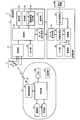
- FIG. 1 is a schematic view showing a schematic configuration of a capsule endoscope system according to an embodiment of the present invention.
- FIG. 2 is a block diagram showing a schematic configuration of a capsule endoscope system according to an embodiment of the present invention.
- FIG. 3 is a view for explaining the configuration of the receiving unit of the receiving apparatus provided in the capsule endoscope system according to the embodiment of the present invention.
- FIG. 4 is a diagram showing a characteristic impedance adjustment and calculation process performed by the capsule endoscope system according to the embodiment of the present invention by a Smith chart suitable for visualizing impedance change of a high frequency circuit.
- FIG. 5 is a view for explaining the configuration of the wireless communication unit of the capsule endoscope provided in the capsule endoscope system according to the embodiment of the present invention.
- FIG. 1 is a schematic view showing a schematic configuration of a capsule endoscope system according to an embodiment of the present invention.
- FIG. 2 is a block diagram showing a schematic configuration of a capsule endoscope system according to
- FIG. 6 is a flowchart showing characteristic impedance adjustment processing performed by the capsule endoscope system according to the embodiment of the present invention.
- FIG. 7 is a view for explaining characteristic impedance adjustment processing performed by the capsule endoscope system according to the first modification of the embodiment of the present invention.
- FIG. 8 is a diagram for explaining characteristic impedance adjustment processing performed by the capsule endoscope system according to the second modification of the embodiment of the present invention.
- FIG. 1 is a schematic view showing a schematic configuration of a capsule endoscope system according to an embodiment of the present invention.
- the capsule endoscope system 1 according to the first embodiment generates image data by being introduced into a subject H and imaging the inside of the subject H, and superimposing it on a carrier wave.
- a capsule endoscope 2 which is a medical device for transmitting a radio signal on radio waves and a plurality of receiving antennas 3a to 3h mounted on a subject H, the radio signal transmitted from the capsule endoscope 2 Image data generated by the capsule endoscope 2 is received from the receiving device 4 via the cradle 5a, and the image data is processed to be received.
- a processing device 5 for generating an image in the sample H.
- the image generated by the processing device 5 is displayed and output from the display device 6, for example.
- image data an image in a state of being converted to a transmission format for transmission from the capsule endoscope 2 to the processing device 5 is referred to as image data.
- the capsule endoscope 2 After being swallowed by the subject H, the capsule endoscope 2 moves in the digestive tract of the subject H by peristaltic movement of an organ or the like, and in advance the living body site (esophagus, stomach, small intestine, large intestine, etc.) Images are sequentially taken at a set reference cycle (for example, 0.5 second cycle). Then, the image data and the related information acquired by this imaging operation are sequentially wirelessly transmitted to the receiving device 4.
- a set reference cycle for example, 0.5 second cycle
- FIG. 2 is a block diagram showing a schematic configuration of a capsule endoscope system according to an embodiment of the present invention.
- the capsule endoscope 2 includes an imaging unit 21, an illumination unit 22, a control unit 23, a wireless communication unit 24, a transmission antenna 25, a memory 26, and a power supply unit 27.
- the capsule endoscope 2 is a device in which the above-described components are incorporated in a capsule-shaped casing of a size that allows the subject H to swallow.
- the imaging unit 21 generates, for example, image data obtained by imaging the inside of the subject H from an optical image formed on a light receiving surface and outputs the image data, and an objective lens disposed on the light receiving surface side of the image pickup device And optical systems.
- the imaging device a plurality of pixels that receive light from the subject H are arranged in a matrix, and photoelectric conversion is performed on the light received by the pixels to generate image data.
- the imaging unit 21 reads out pixel values for each horizontal line with respect to a plurality of pixels arranged in a matrix, and generates image data including a plurality of line data to which a synchronization signal is added for each horizontal line.
- the imaging unit 21 is configured by a charge coupled device (CCD) imaging device or a complementary metal oxide semiconductor (CMOS) imaging device.
- CCD charge coupled device
- CMOS complementary metal oxide semiconductor
- the illumination unit 22 is configured of a white light emitting diode (LED) or the like that generates white light that is illumination light.
- white light may be generated by multiplexing light from a plurality of LEDs having different emission wavelength bands or laser light sources, etc.
- a xenon lamp, a halogen lamp, or the like may be used. You may do so.
- the control unit 23 controls operation processing of each component of the capsule endoscope 2. For example, when the imaging unit 21 performs imaging processing, the imaging unit 21 is controlled to execute exposure and readout processing on the imaging device, and illumination of the illumination unit 22 according to the exposure timing of the imaging unit 21 is performed. Control to emit light. Further, the control unit 23 determines the light emission time of the illumination unit 22 at the next imaging time from the pixel value (luminance value) of the image data captured by the imaging unit 21 and emits the illumination light with the determined light emission time. The illumination unit 22 is controlled to do this. As described above, the light emission time by the illumination unit 22 is controlled based on the image data captured by the control unit 23, and the light emission time may change each time imaging is performed.
- the control unit 23 is configured using a general purpose processor such as a central processing unit (CPU) or a dedicated processor such as various arithmetic circuits that execute a specific function such as an application specific integrated circuit (ASIC).
- CPU central processing unit
- ASIC application specific integrated circuit
- the wireless communication unit 24 performs modulation processing on the image data output from the imaging unit 21 and transmits the image data to the outside.
- the wireless communication unit 24 performs A / D conversion and predetermined signal processing on the image data output from the imaging unit 21 to obtain digital format image data, superimposes it on a carrier together with related information, and transmits the transmission antenna. Radio transmission from 25 to the outside.
- the related information includes identification information (for example, a serial number) assigned to identify the individual of the capsule endoscope 2 and the like.
- the detailed configuration of the wireless communication unit 24 will be described later.
- the transmitting antenna 25 is an element at the end of the wireless signal transmission side in the wireless signal transmission path in which the capsule endoscope 2 and the receiving antenna unit 3 wirelessly communicate (transmission side transmission path end element) It becomes.
- the memory 26 stores an execution program and a control program for the control unit 23 to execute various operations, and parameters such as a threshold. In addition, the memory 26 may temporarily store image data and the like subjected to signal processing in the wireless communication unit 24.
- the memory 26 is configured by a random access memory (RAM), a read only memory (ROM), and the like.
- the power supply unit 27 includes a battery formed of a button battery or the like, a power supply circuit for supplying power to each unit, and a power supply switch for switching the on / off state of the power supply unit 27. Power is supplied to each part in the endoscope 2.
- the power switch is, for example, a reed switch whose on / off state is switched by an external magnetic force, and is external to the capsule endoscope 2 before using the capsule endoscope 2 (before the subject H swallows). Can be switched on by applying a magnetic force.
- the receiving antenna unit 3 has a plurality of (eight in FIG. 1) receiving antennas 3a to 3h.
- the receiving antennas 3a to 3h are realized using, for example, a loop antenna or a dipole antenna, and are disposed at predetermined positions on the external surface of the subject H.
- the receiving antennas 3a to 3h are elements of the end portion on the wireless signal receiving side in the wireless signal transmission path through which the capsule endoscope 2 and the receiving antenna unit 3 wirelessly communicate (receiving side transmission path end element) It becomes.
- the receiving device 4 includes a receiving unit 41, an operation unit 42, a data transmitting / receiving unit 43, an output unit 44, a control unit 45, a storage unit 46, and a power supply unit 47.
- the receiving unit 41 receives the radio signal wirelessly transmitted by the capsule endoscope 2. Specifically, image data and related information wirelessly transmitted from the capsule endoscope 2 are received via the receiving antenna unit 3. For example, the receiving unit 41 performs predetermined signal processing such as demodulation processing and A / D conversion on the received image data. The detailed configuration of the receiving unit 41 will be described later.
- the operation unit 42 is an input device used when the user inputs various setting information and instruction information to the reception device 4.
- the operation unit 42 is, for example, a switch, a button, or the like provided on the operation panel of the reception device 4.
- the data transmitting / receiving unit 43 transmits the image data and the related information stored in the storage unit 46 to the processing device 5 when connected in a communicable state with the processing device 5.
- the data transmission / reception unit 43 is configured by a communication interface such as a LAN.
- the output unit 44 displays an image, outputs sound or light, and generates vibration.
- the output unit 44 displays an image or emits sound, light, or vibration.
- the output unit 44 is configured by at least one of a display such as a liquid crystal display and an organic EL display, a speaker, a light source such as an LED, and a vibration generator such as a vibration motor.
- the control unit 45 controls each component of the receiving device 4.
- the control unit 45 is configured using a general purpose processor such as a CPU or a dedicated processor such as various arithmetic circuits that execute a specific function such as an ASIC.
- the storage unit 46 stores a program for operating the receiving device 4 to execute various functions, image data acquired by the capsule endoscope 2, and the like.
- the storage unit 46 is configured by a RAM, a ROM, and the like.
- the storage unit 46 stores a characteristic impedance adjustment information storage unit 461 that stores information for adjusting the characteristic impedance between the receiving antenna (the receiving antennas 3a to 3h) and the circuit of the receiving unit 41 in the receiving device 4. Have.
- the power supply unit 47 supplies power to each unit of the receiving device 4.
- the power supply unit 47 is configured using a battery made of a battery or the like.
- Such an imaging device 4 is ejected while passing through the digestive tract, for example, after the capsule endoscope 2 is swallowed by the subject H while imaging is performed by the capsule endoscope 2 Until then, the subject H is worn and carried. During this time, the reception device 4 stores the image data received via the reception antenna unit 3 in the storage unit 46.
- the receiving device 4 is removed from the subject H and set in a cradle 5 a (see FIG. 1) connected to the processing device 5. As a result, the receiving device 4 is connected in a communicable state with the processing device 5, and transfers (downloads) the image data and the related information stored in the storage unit 46 to the processing device 5.
- the processing device 5 is configured using, for example, a workstation provided with a display device 6 such as a liquid crystal display.
- the processing device 5 includes a data transmission / reception unit 51, an image processing unit 52, a control unit 53 that integrally controls the respective units, a display control unit 54, an input unit 55, and a storage unit 56.
- the data transmission / reception unit 51 is connected to the reception device 4 via the cradle 5 a and transmits / receives data to / from the reception device 4.
- the data transmission / reception unit 51 is configured by a communication interface such as USB or LAN.
- the image processing unit 52 reads a predetermined program stored in a storage unit 56 described later to generate information useful for observation or diagnosis of the image data input from the data transmitting / receiving unit 51. Perform image processing.
- the image processing unit 52 is realized by a processor such as a CPU or an ASIC.
- the control unit 53 configures the processing device 5 based on the signal input through the input unit 55 and the image data input from the data transmission / reception unit 51 by reading various programs stored in the storage unit 56. It instructs and transfers data to each unit to control the entire operation of the processing device 5 in a centralized manner.
- the control unit 53 is realized by a processor such as a CPU or an ASIC.
- the display control unit 54 causes the display device 6 to display the image after performing predetermined processing such as thinning out of data according to the display range of the image on the display device 6 and gradation processing.
- the display control unit 54 is configured by, for example, a processor such as a CPU or an ASIC.
- the input unit 55 receives an input of information or an instruction according to the user's operation.
- the input unit 55 is realized by an input device such as a keyboard, a mouse, a touch panel, and various switches.
- the storage unit 56 is a program for operating the processing device 5 to execute various functions, various information used during execution of the program, and image data and related information acquired via the receiving device 4
- the in-vivo image etc. which were produced by the image processing part 52 are memorize
- the storage unit 56 is realized by a semiconductor memory such as a flash memory, a RAM, and a ROM, a recording medium such as an HDD, an MO, a CD-R, and a DVD-R, and a drive device for driving the recording medium.
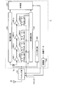
- FIG. 3 is a view for explaining the configuration of the receiving unit of the receiving apparatus provided in the capsule endoscope system according to the embodiment of the present invention.
- the receiving unit 41 includes a matching unit 411, a pulse generation unit 412, a voltage detection unit 413, a phase detection unit 414, inverters 415-1 to 415-n (n is a natural number), D-type flip flops 416-1 to 416-n, A calculation unit 417, an amplification unit 418, a mixer 419, and a filter 420 are included.
- Matching unit 411 the device (in this embodiment, at least one receiving antennas 3a ⁇ 3h) and, connected are between the configured circuit C 1 except matching unit 411 in the receiver 41 .
- matching units 411 are individually provided for the receiving antennas 3a to 3h.
- Matching unit 411 is capable of changing its characteristic impedance, the characteristic impedance of the device by changing its characteristic impedance based on the calculation result of the calculator 417, the characteristic impedance of the circuit C 1 Matching.
- the matching unit 411 includes, for example, a characteristic impedance conversion circuit and a control unit that changes the circuit multiplier of the characteristic impedance conversion circuit.
- the control unit included in the matching unit 411 is configured by, for example, a microcontroller.
- Pulse generating unit 412 generates the characteristic impedance of the calculated reception antenna side, a pulse signal S A to be used for matching the characteristic impedance of the circuit C 1. Pulse generator 412, a pulse signal S A generated is output to the voltage detection unit 413 and the inverter 415-1 ⁇ 415-n.
- the pulse generation unit 412 is configured using an oscillation circuit such as crystal.
- the voltage detection unit 413 detects the voltage of the reflected signal S B (second signal) in which the pulse signal S A is reflected by the matching unit 411. In this case, although the pulse signal S A is transmitted directly to the voltage detection unit 413, the voltage detecting unit 413, detection may not be performed in the voltage of the direct transmission pulse signal S A (first signal).
- the voltage detection unit 413 is configured by, for example, a microcontroller having a voltage sensor, a microcomputer, an analog digital converter, or the like.
- Phase detector 414 determines a reflective signal S B is inputted to the inverter 415-1 timing, the inverter pulse signal S A is input (either of the inverters 415-1 ⁇ 415-n), the inverter from the delay time between, for detecting a phase difference between the pulse signals S a and the reflected signal S B.
- the phase detection unit 414 is configured of, for example, a microcontroller or a microcomputer.
- the inverters 415-1 to 415-n each have the same delay amount. Pulse signal S A or reflected signal S B is an inverter 415-1,415-2, ..., are input in the order of 415-n.
- the inverters 415-1 to 415-n are connected in series, and the inputted signals are output to the adjacent inverters, and any of the D-type flip flops (D-type flip flops 416-1 to 416-n) connected Output to The inverters 415-1 to 415-n constitute a delay unit.
- the D-type flip flops 416-1 to 416-n invert the signal in a predetermined D-type flip flop among the input signals, and output the inverted signal to the phase detection unit 414.
- the D-type flip-flops 416-1 to 416-n are D-type flip-flops (for example, D-type flip-flops 416-2, 416-4,...) To which signals input to the odd-numbered inverters are input. ⁇ ) Outputs the signal as it is to the phase detection unit 414 without inverting, and the D type flip flop (for example, D type flip flop 416-1, 416-3) to which the signal input to the even-numbered inverter is input. ,...) Output the inverted signal to the phase detection unit 414.
- the waveform of the signal input to the phase detection unit 414 is aligned by using a D-type flip flop.
- the D-type flip flops 416-1 to 416-n output the input signal or its inverted signal to the phase detection unit 414 based on the clock input from the outside.
- Calculation unit 417 the connection portion of the voltage which the voltage detecting unit 413 detects a phase difference the phase detector 414 detects, on the basis of the characteristic impedance of the matching portion 411, a matching unit 411 and the circuit portion C 1
- the characteristic impedance on the receiving antenna side is calculated based on
- the calculating unit 417 outputs the calculated characteristic impedance on the receiving antenna side to the matching unit 411.
- the calculation unit 417 is configured by, for example, a microcontroller or a microcomputer.
- the matching unit 411 acquires the characteristic impedance from the calculation unit 417, with reference to the change value of the characteristic impedance conversion circuit is determined based on the Smith chart, the characteristic impedance of the circuit C 1, the receiving antenna side characteristic impedance And changes its own characteristic impedance so as to match, and feeds back the changed characteristic impedance to the calculation unit 417.
- the above-described change values are stored in advance in the characteristic impedance adjustment information storage unit 461, for example, as a table in which each change value is associated with the characteristic impedance.
- FIG. 4 is a diagram showing a characteristic impedance adjustment and calculation process performed by the capsule endoscope system according to the embodiment of the present invention by a Smith chart suitable for visualizing impedance change of a high frequency circuit.
- Matching unit 411 performs a characteristic impedance input from the calculation unit 417, a Smith chart 462 shown in FIG. 4, the characteristic impedance adjusted to the characteristic impedance is within acceptable region R 1.
- the characteristic impedance of the calculated by the calculation unit 417 receiving antenna side to fall within the allowable region R 1, to adjust the characteristic impedance by the matching unit 411 and the circuit section C 1.
- the allowable range R 1 is calculated based on, for example, a constant noise index circle calculated from the minimum noise index of the amplification unit 418.
- the noise figure is the ratio of the input S / N to the output S / N at the amplifier 418. Further, the allowable region R 1 in the Smith chart 462, use conditions of the receiving apparatus 4 and the capsule endoscope 2, varies depending on the purpose or the like.
- the matching unit 411 is not limited to the Smith chart described above, but may store in advance in the characteristic impedance adjustment information storage unit 461 a table in which the value fed back from the calculation unit 417 is associated with the matching method. Characteristic impedance adjustment may be performed with reference to this table.
- the amplification unit 418 amplifies the radio signal (image data) input from the reception antenna via the matching unit 411 at a preset amplification factor.
- the amplification unit 418 is configured using, for example, a low noise amplifier.
- the mixer 419 converts the frequency of the signal amplified by the amplification unit 418 into a frequency suitable for the circuit in the subsequent stage.
- the mixer 419 is configured using, for example, a diode.
- the filter 420 passes only signals of a predetermined frequency band.
- the signal that has passed through the filter 420 is output to the control unit 45.
- the receiving unit 41 measures the received signal strength indicator (RSSI) of the wireless signals received by the receiving antennas 3a to 3h.
- the receiving unit 41 measures the reception strength at the time of receiving the wireless signal for each of the receiving antennas 3a to 3h. At this time, all measured reception strengths and the image data received by the receiving unit 41 may be associated with each other and stored in the storage unit 46.
- the receiving unit 41 selects the antenna with the highest reception strength among the reception antennas 3a to 3h based on the reception strength, and receives the radio signal received by the selected antenna.
- the radio signal received at this time is a signal that has passed through the filter 420.
- FIG. 5 is a view for explaining the configuration of the wireless communication unit of the capsule endoscope provided in the capsule endoscope system according to the embodiment of the present invention.
- the wireless communication unit 24 includes a matching unit 241, a pulse generation unit 242, a voltage detection unit 243, a phase detection unit 244, inverters 245-1 to 245-m (m is a natural number), and D-type flip flops 246-1 to 246-m. , Calculation unit 247, and amplification unit 248.
- Matching unit 241 includes a device (transmitting antenna 25 in this embodiment), is connected between the circuit portion C 2 configured except matching unit 241 in the wireless communication unit 24.
- Matching unit 241 is capable of changing its characteristic impedance, the characteristic impedance of the transmission antenna 25 by changing its characteristic impedance based on the calculation result of the calculator 247, the characteristics of circuit portion C 2 Match the impedance.
- the matching unit 241 includes, for example, a characteristic impedance conversion circuit and a control unit that changes the circuit multiplier of the characteristic impedance conversion circuit.
- the control unit included in the matching unit 411 is configured by, for example, a microcontroller.
- Pulse generating unit 242 generates the characteristic impedance of the transmission antenna 25, a pulse signal S C to be used for matching the characteristic impedance of the circuit C 2.
- Pulse generator 242, a pulse signal S C generated is output to the voltage detection unit 243 and the inverter 245-1 ⁇ 245-m.
- the pulse generation unit 242 is configured using an oscillation circuit such as crystal.
- the voltage detection unit 243 detects the voltage of the reflected signal S D (second signal) in which the pulse signal S C is reflected by the matching unit 241. In this case, although the pulse signal S C is transmitted directly to the voltage detection unit 243, the voltage detecting unit 243, detection may not be performed in the voltage of the direct transmission pulse signal S C (first signal).
- the voltage detection unit 243 is configured by, for example, a microcontroller having a voltage sensor, a microcomputer, an analog digital converter, or the like.
- Phase detector 244 determines a reflective signal S D is input to the inverter 245-1 timing, the inverter pulse signal S C is inputted (either inverters 245-1 ⁇ 245-m), the inverter from the delay time between, for detecting a phase difference between the pulse signal S C and the reflected signal S D.
- the phase detection unit 244 is configured of, for example, a microcontroller or a microcomputer.
- the inverters 245-1 to 245-m each have the same delay amount. Pulse signal S C or reflected signal S D, the inverter 245-1,245-2, ..., it is input in the order of 245-m.
- the inverters 245-1 to 245-m are connected in series, and output the input signal to the adjacent inverters, and at the same time, any of the D-type flip flops (D-type flip flops 246-1 to 246-m) connected.
- Output to Inverters 245-1 to 245-m constitute a delay unit.
- the D-type flip flops 246-1 to 246-m invert the signal in a predetermined D-type flip flop among the input signals, and output the inverted signal to the phase detection unit 244.
- the D-type flip-flops 246-1 to 246-m receive D-type flip-flops (for example, D-type flip-flops 246-2, 246-4,...) To which signals input to the odd-numbered inverters are input. ⁇ ) Outputs the signal as it is to the phase detection unit 244 without inverting, and D-type flip-flops (eg, D-type flip-flops 246-1 and 246-3) to which signals input to the even-numbered inverters are input. ,...) Output the inverted signal to the phase detection unit 244.
- the D-type flip flops 246-1 to 246-m output the input signal or its inverted signal to the phase detection unit 244 based on the clock input from the outside.
- Calculation unit 247 the connection portion of the voltage which the voltage detecting unit 243 detects a phase difference the phase detector 244 detects, on the basis of the characteristic impedance of the matching portion 241, a matching unit 241 and the circuit portion C 2
- the characteristic impedance of the transmitting antenna 25 is calculated based on the following equation.
- the calculating unit 247 outputs the calculated characteristic impedance on the transmitting antenna 25 side to the matching unit 241.
- the calculation unit 247 is configured of, for example, a microcontroller or a microcomputer.
- the matching unit 241 when the calculation unit 247 obtains a characteristic impedance, with reference to the change value of the characteristic impedance conversion circuit is determined based on the procedure as described above, the characteristic impedance of the circuit C 2, transmitting antennas 25
- the characteristic impedance of one's own is changed so as to match with the characteristic impedance of and the characteristic impedance after the change is fed back to the calculation unit 247.
- the above-described change values are stored in advance in the memory 26 as a table in which each change value is associated with the characteristic impedance.
- the matching unit 241 performs characteristic impedance adjustment so that the characteristic impedance input from the calculation unit 247 falls within the allowable range in the Smith chart as described above.
- the characteristic impedance of the calculated by the calculation unit 247 transmitting antenna 25 side so as to fall in the allowable region, to adjust the characteristic impedance by the matching unit 241 and the circuit portion C 2.
- the allowable range is calculated based on, for example, a constant power gain circle calculated from the maximum available power gain of the amplification unit 248.
- the maximum available power gain is the maximum power gain obtained when the characteristic impedance is matching.
- the allowable area in the Smith chart showing the characteristic impedance adjustment and calculation processing by the radio communication unit 24 also, use conditions of the receiving apparatus 4 and the capsule endoscope 2, varies depending on the purpose or the like. In some cases, there may an allowable region R 1 of the receiver 41 in the Smith chart, and the allowable area of the wireless communication unit 24 matches.
- the amplification unit 248 amplifies the image data captured by the imaging unit 21 at a preset amplification factor, and outputs the amplified image data to the transmission antenna 25 via the matching unit 241.
- the amplification unit 248 is configured using, for example, a power amplifier.
- FIG. 6 is a flowchart showing characteristic impedance adjustment processing performed by the capsule endoscope system according to the embodiment of the present invention.
- characteristic impedance adjustment processing by the wireless communication unit 24 which is executed when the capsule endoscope 2 is in operation will be described as an example.
- the characteristic impedance adjustment process is similarly performed in the receiving unit 41 as well.
- the pulse generation unit 242 determines whether it is a pulse transmission time (step S101). The pulse generation unit 242 determines whether a predetermined time has elapsed from the time when the pulse signal was generated last time. Here, when it is determined that the pulse generation unit 242 does not have a pulse transmission time (step S101: No), the determination of the pulse transmission time is repeated. On the other hand, when it is determined that it is the pulse transmission time (step S101: Yes), the pulse generation unit 242 generates (transmits) a pulse signal (step S102). In the present embodiment, a pulse of a predetermined voltage is generated once.
- step S103 the voltage detecting unit 243, the pulse signal S C detects the voltage of the reflected signal S D reflected by the matching unit 241.
- step S104 the phase detector 244, the reflected signal S D and inverter is input (inverter 245-1), the inverter (inverter 245-1 to 245 pulse signal S C is input at the timing from either) of -m, it detects the phase difference between the pulse signal S C and the reflected signal S D.
- step S103 mentioned above and step S104 may be performed simultaneously.
- step S105 the calculation unit 247 uses the voltage detected by the voltage detection unit 243 in step S103, the phase difference detected by the phase detection unit 244 in step S104, and the characteristic impedance of the matching unit 241. to, to calculate the characteristic impedance of the transmission antenna 25 side connection portion between the matching unit 241 and the circuit portion C 2 as a base point.
- the calculating unit 247 outputs the calculated characteristic impedance on the transmitting antenna 25 side to the matching unit 241.
- step S106 the matching unit 241 determines whether the characteristic impedance of the transmission antenna 25 matches the characteristic impedance of the circuit unit C 2 based on the characteristic impedance acquired from the calculation unit 247. Do. At this time, the matching unit 241, if the characteristic impedance of the transmission antenna 25 and the circuit portion C 2 is determined not to match (step S106: No), the process proceeds to step S107.
- step S107 the matching unit 241 performs characteristic impedance matching. As described above, the matching unit 241 changes its characteristic impedance to match the characteristic impedance of the transmitting antenna 25 with the characteristic impedance of the circuit unit C 2 with reference to the table stored in the memory 26. Do. Also, the matching unit 241 feeds back the changed characteristic impedance to the calculation unit 247. Thereafter, the process returns to step S102, and the above-described process is repeated.
- step S106 determines that the characteristic impedances of the transmission antenna 25 and the circuit of the wireless communication unit 24 match.
- step S108 the wireless communication unit 24 wirelessly transmits the image data via the transmission antenna 25.
- matching is performed at timing when the transmitting antenna 25 does not transmit image data.
- matching is executed at timing when the receiving antennas 3a to 3h do not receive image data.
- step S109 the wireless communication unit 24 determines whether to continue the above-described characteristic impedance adjustment process. For example, if the wireless communication unit 24 has not received an instruction to end the process via the receiving device 4, the wireless communication unit 24 determines to continue the process. If the wireless communication unit 24 determines that the characteristic impedance adjustment process is to be continued (Yes at Step S109), the process returns to Step S101, and the above-described process is repeated. On the other hand, when the wireless communication unit 24 determines that the characteristic impedance adjustment process is not to be continued (step S109: No), the above-described process ends.
- the receiving unit 41 and the wireless communication unit 24 the phase difference between the pulse signal generated by the pulse generating unit and the reflection signal of the pulse signal reflected by the matching unit, and the voltage of the reflection signal.
- the characteristic impedance of the antenna By calculating the characteristic impedance of the antenna on the basis of the connection portion between the matching unit and the circuit unit on the basis of the detected phase difference and voltage, and feeding back the calculation result.
- the characteristic impedance of the circuit of the reception unit 41 or the wireless communication unit 24 and the antenna connected to each of the circuits is adjusted. According to the present embodiment, since the characteristic impedance between the circuit and the antenna is adjusted, stable wireless communication can be performed between devices that transmit and receive data.
- an inverter is used as a configuration for detecting a phase difference.
- an RC circuit configured using a resistor and a capacitor
- an LC circuit configured using a coil and a capacitor Or may be a buffer.
- the characteristic impedance is calculated for each receiving antenna in the receiving unit 41 and the characteristic impedance is matched for each receiving antenna individually (see, for example, FIG. 3).
- one matching unit connected to a plurality of receiving antennas is provided as the receiving unit 41, the characteristic impedance of all the plurality of receiving antennas is calculated, and the characteristic impedance is matched to the entire receiving antenna. You may do so.
- FIG. 7 is a view for explaining characteristic impedance adjustment processing performed by the capsule endoscope system according to the first modification of the embodiment of the present invention.
- the capsule endoscope system according to the first modification is the same as the capsule endoscope system 1 described above, and thus the description thereof is omitted.
- processing different from that of the above-described embodiment will be described with reference to FIG.
- the pulse generation unit 242 generates (transmits) a plurality of pulses having different input pulse voltages. Specifically, the pulse generator 242 generates a pulse signal three times while changing the output. At this time, the phase and pulse width of each pulse signal are adjusted to be the same.
- the voltage detection unit 243 detects three sets of voltages in which the voltage of the pulse signal (input pulse voltage) and the voltage of the reflection signal (reflected wave voltage) are set (step S103).
- the voltage detection unit 243 calculates an approximate straight line (approximated straight line L 1 shown in FIG. 7) indicating the relationship between the input pulse voltage and the reflected wave voltage from the three sets of detection results.
- the voltage detection unit 243 reads the reflected wave voltage at the input pulse voltage set in advance from the approximate straight line and outputs it to the calculation unit 247. For example, as shown in FIG. 7, the reflected wave voltage V re at the input pulse voltage V in having an intermediate value among the three input pulse voltages is read.
- the input pulse voltage may acquire the voltage of the pulse generated by the pulse generator 242, and the voltage detector 243 may detect only the voltage of the reflection signal.
- phase detection unit 244 detects the phase difference between the pulse signal and the reflection signal three times (step S104).
- the phase and the pulse width are adjusted to be the same, so the phase difference is almost the same.
- phase detector 244 any of the three phase difference, for example, may output a phase difference calculation unit 247 in the same input pulse voltage V in the input pulse voltage, three phase The average value of these may be calculated and output to the calculation unit 247.
- step S105 the calculation unit 247 calculates the characteristic impedance of the circuit of the wireless communication unit 24 based on the detection result of the voltage detection unit 243 and the detection result of the phase detection unit 244.
- the subsequent steps are the same as in the above-described embodiment.
- the voltage detection unit 243 detects a plurality of pulses whose input pulse voltages are different from each other, and the calculation unit 247 calculates the characteristic impedance based on the detection result.
- the detection accuracy of the voltage to be detected is improved as compared with the above-described embodiment, and as a result, the calculation accuracy of the characteristic impedance can be improved.
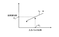
- FIG. 8 is a diagram for explaining characteristic impedance adjustment processing performed by the capsule endoscope system according to the second modification of the embodiment of the present invention.
- the capsule endoscope system according to the second modification is the same as the capsule endoscope system 1 described above, and thus the description thereof is omitted.
- processing different from that of the above-described embodiment will be described with reference to FIG.
- the pulse generation unit 242 generates (transmits) a plurality of pulses having different characteristic impedances of elements connected to the pulse generation unit. Specifically, the pulse generator 242 generates a pulse signal three times while changing the phase of the pulse signal. At this time, the input pulse voltage of each pulse signal is adjusted to be the same.
- the phase detection unit 244 detects the phase difference between the pulse signal and the reflection signal three times (step S104).
- the phase detection unit 244 calculates an approximate straight line (approximated straight line L 2 shown in FIG. 8) indicating the relationship between the input pulse phase and the reflected wave phase from the three sets of detection results.
- the voltage detection unit 243 detects the voltage (reflected wave voltage) of the reflection signal of each pulse signal (step S103).
- the input pulse voltages are adjusted to be the same, so that the reflected wave voltages to be detected are substantially the same. Therefore, the voltage detection unit 243 may output, to the calculation unit 247, a reflected wave voltage corresponding to any one of the three detection voltages, for example, the pulse signal generated for the second time, or the reflected wave.
- An average of the voltages may be calculated, and the average value may be output to the calculation unit 247.
- step S105 the calculation unit 247 calculates the characteristic impedance based on the detection result by the voltage detection unit 243 and the detection result by the phase detection unit 244.
- the subsequent steps are the same as in the above-described embodiment.
- the phase detection unit 244 detects a plurality of pulses having different characteristic impedances, and the calculation unit 247 calculates the characteristic impedance based on the detection result.
- the detection accuracy of the phase difference to be detected can be improved as compared with the above-described embodiment, and as a result, the calculation accuracy of the characteristic impedance can be improved.
- the pulse generation unit 242 generates pulse signals in which the input pulse voltage and the characteristic impedance are different from each other, and the calculation unit 247 performs the processing of modification 1 on the detected voltage, and the processing of modification 2 on the detected phase difference. To calculate the characteristic impedance.
- the wireless communication unit 24 has been described as an example, but the present invention is also applicable to the receiving unit 41.
- an executable program for each process executed by each component of the capsule endoscope, the receiving device, and the processing device of the capsule endoscope system according to the above-described embodiment can be installed or can be executed. It may be configured to be recorded in a computer readable recording medium such as a CD-ROM, a flexible disk (FD), a CD-R, a DVD and the like in the form of a file and provided, and is connected to a network such as the Internet It may be stored on a computer and configured to be provided by being downloaded via a network. Further, it may be configured to provide or distribute via a network such as the Internet.
- a system in which a radio signal is generated and output by the capsule endoscope 2 which is a medical device has been described as an example, but a capsule type may be used if it generates and outputs a radio signal. It is not limited to the endoscope system. For example, it is also possible to apply to a system using a pacemaker or the like that is attached to a subject and can generate and output a wireless signal.
- the communication module, the capsule endoscope, and the receiving unit according to the present invention are useful for performing stable wireless communication between devices that transmit and receive data.
Landscapes
- Engineering & Computer Science (AREA)
- Health & Medical Sciences (AREA)
- Life Sciences & Earth Sciences (AREA)
- Computer Networks & Wireless Communication (AREA)
- Signal Processing (AREA)
- Surgery (AREA)
- Radiology & Medical Imaging (AREA)
- Heart & Thoracic Surgery (AREA)
- Optics & Photonics (AREA)
- Pathology (AREA)
- Biophysics (AREA)
- Physics & Mathematics (AREA)
- Biomedical Technology (AREA)
- Nuclear Medicine, Radiotherapy & Molecular Imaging (AREA)
- Medical Informatics (AREA)
- Molecular Biology (AREA)
- Animal Behavior & Ethology (AREA)
- General Health & Medical Sciences (AREA)
- Public Health (AREA)
- Veterinary Medicine (AREA)
- Endoscopes (AREA)
Abstract
Selon la présente invention, ce module de communication est pourvu d'un dispositif ayant une première impédance caractéristique, d'une unité de circuit ayant une deuxième impédance caractéristique, et d'une unité de mise en correspondance, l'unité de circuit comprenant une unité de retard qui est formée par connexion en série d'une pluralité d'éléments ayant chacun une quantité de retard prédéfinie, une unité de génération de signal qui génère un signal à émettre à l'unité de retard, une unité de détection de phase qui détecte une différence de phase entre un premier signal obtenu par le signal qui est directement émis à l'unité de retard et un second signal obtenu par le signal qui est réfléchi par l'unité de mise en correspondance, une unité de détection de tension qui détecte la tension du second signal, et une unité de calcul qui, sur la base de la différence de phase et de la tension du second signal, calcule une troisième impédance caractéristique sur le côté dispositif avec une partie de connexion de l'unité d'adaptation et de l'unité de circuit en tant que point de base, et l'unité de mise en correspondance fait correspondre les première et deuxième impédances caractéristiques sur la base de la troisième impédance caractéristique.
Applications Claiming Priority (2)
| Application Number | Priority Date | Filing Date | Title |
|---|---|---|---|
| JP2017235465 | 2017-12-07 | ||
| JP2017-235465 | 2017-12-07 |
Publications (1)
| Publication Number | Publication Date |
|---|---|
| WO2019111470A1 true WO2019111470A1 (fr) | 2019-06-13 |
Family
ID=66750154
Family Applications (1)
| Application Number | Title | Priority Date | Filing Date |
|---|---|---|---|
| PCT/JP2018/033149 Ceased WO2019111470A1 (fr) | 2017-12-07 | 2018-09-07 | Module de communication, endoscope à capsule et unité de réception |
Country Status (1)
| Country | Link |
|---|---|
| WO (1) | WO2019111470A1 (fr) |
Citations (5)
| Publication number | Priority date | Publication date | Assignee | Title |
|---|---|---|---|---|
| JPH0210922A (ja) * | 1988-06-28 | 1990-01-16 | Fujitsu Ltd | デジタル位相差検出回路及び位相差検出方法 |
| JP2006246322A (ja) * | 2005-03-07 | 2006-09-14 | Hitachi Kokusai Electric Inc | 整合器 |
| JP2009050541A (ja) * | 2007-08-28 | 2009-03-12 | Olympus Corp | 被検体内位置検出システム |
| JP2009516963A (ja) * | 2005-11-18 | 2009-04-23 | クゥアルコム・インコーポレイテッド | 無線通信のためのディジタル送信機 |
| WO2017164228A1 (fr) * | 2016-03-24 | 2017-09-28 | デクセリアルズ株式会社 | Dispositif de transmission, dispositif de commande d'antenne, procédé de réglage, et programme d'exécution d'un procédé de réglage |
-
2018
- 2018-09-07 WO PCT/JP2018/033149 patent/WO2019111470A1/fr not_active Ceased
Patent Citations (5)
| Publication number | Priority date | Publication date | Assignee | Title |
|---|---|---|---|---|
| JPH0210922A (ja) * | 1988-06-28 | 1990-01-16 | Fujitsu Ltd | デジタル位相差検出回路及び位相差検出方法 |
| JP2006246322A (ja) * | 2005-03-07 | 2006-09-14 | Hitachi Kokusai Electric Inc | 整合器 |
| JP2009516963A (ja) * | 2005-11-18 | 2009-04-23 | クゥアルコム・インコーポレイテッド | 無線通信のためのディジタル送信機 |
| JP2009050541A (ja) * | 2007-08-28 | 2009-03-12 | Olympus Corp | 被検体内位置検出システム |
| WO2017164228A1 (fr) * | 2016-03-24 | 2017-09-28 | デクセリアルズ株式会社 | Dispositif de transmission, dispositif de commande d'antenne, procédé de réglage, et programme d'exécution d'un procédé de réglage |
Similar Documents
| Publication | Publication Date | Title |
|---|---|---|
| JP4383410B2 (ja) | 無線型被検体内情報取得システム、被検体内導入装置および被検体外部装置 | |
| KR100741217B1 (ko) | 무선형 피검체 내 정보 취득 시스템 및 피검체 외부 장치 | |
| KR100739913B1 (ko) | 무선형 피검체 내 정보 취득 시스템 및 피검체 내 도입장치 | |
| JP4422679B2 (ja) | カプセル内視鏡およびカプセル内視鏡システム | |
| JPWO2004096029A1 (ja) | カプセル内視鏡およびカプセル内視鏡システム | |
| JP6084339B2 (ja) | カプセル型内視鏡システム及びカプセル型内視鏡システムの作動方法 | |
| US11234578B2 (en) | Receiving apparatus and radio wave interference determination method | |
| JPWO2010050400A1 (ja) | 画像処理装置および画像処理方法 | |
| US10777881B2 (en) | Receiving antenna, receiving antenna unit, and receiving system | |
| WO2021176708A1 (fr) | Système d'antenne, système d'endoscope à capsule et procédé de fonctionnement d'un système d'antenne | |
| WO2019111470A1 (fr) | Module de communication, endoscope à capsule et unité de réception | |
| JP2006020778A (ja) | 被検体内導入装置および医療装置 | |
| JP2007089892A (ja) | 被検体内導入装置、被検体外装置および被検体内導入システム | |
| JP4370198B2 (ja) | 被検体内導入装置 | |
| JP6230511B2 (ja) | 内視鏡装置 | |
| WO2020144862A1 (fr) | Système d'endoscope à capsule et dispositif de réception | |
| US20200373955A1 (en) | Receiving device and receiving method | |
| US20200196845A1 (en) | Capsule endoscope system, capsule endoscope, and receiving device | |
| JP2005334080A (ja) | 被検体内導入装置および医療装置 | |
| JP2006149686A (ja) | 位置検出装置および被検体内導入システム | |
| JP4025766B2 (ja) | 受信装置および送信装置 | |
| JP2005287685A (ja) | 被検体外装置、被検体内導入装置および被検体内導入システム | |
| WO2021064882A1 (fr) | Système de réception |
Legal Events
| Date | Code | Title | Description |
|---|---|---|---|
| 121 | Ep: the epo has been informed by wipo that ep was designated in this application |
Ref document number: 18886886 Country of ref document: EP Kind code of ref document: A1 |
|
| NENP | Non-entry into the national phase |
Ref country code: DE |
|
| 122 | Ep: pct application non-entry in european phase |
Ref document number: 18886886 Country of ref document: EP Kind code of ref document: A1 |
|
| NENP | Non-entry into the national phase |
Ref country code: JP |