WO2019111694A1 - Structure de connecteur et connecteur de fil électrique - Google Patents
Structure de connecteur et connecteur de fil électrique Download PDFInfo
- Publication number
- WO2019111694A1 WO2019111694A1 PCT/JP2018/042769 JP2018042769W WO2019111694A1 WO 2019111694 A1 WO2019111694 A1 WO 2019111694A1 JP 2018042769 W JP2018042769 W JP 2018042769W WO 2019111694 A1 WO2019111694 A1 WO 2019111694A1
- Authority
- WO
- WIPO (PCT)
- Prior art keywords
- connector
- wire
- housing
- electric wire
- terminal
- Prior art date
- Legal status (The legal status is an assumption and is not a legal conclusion. Google has not performed a legal analysis and makes no representation as to the accuracy of the status listed.)
- Ceased
Links
Images







Classifications
-
- H—ELECTRICITY
- H01—ELECTRIC ELEMENTS
- H01R—ELECTRICALLY-CONDUCTIVE CONNECTIONS; STRUCTURAL ASSOCIATIONS OF A PLURALITY OF MUTUALLY-INSULATED ELECTRICAL CONNECTING ELEMENTS; COUPLING DEVICES; CURRENT COLLECTORS
- H01R13/00—Details of coupling devices of the kinds covered by groups H01R12/70 or H01R24/00 - H01R33/00
- H01R13/646—Details of coupling devices of the kinds covered by groups H01R12/70 or H01R24/00 - H01R33/00 specially adapted for high-frequency, e.g. structures providing an impedance match or phase match
- H01R13/6461—Means for preventing cross-talk
- H01R13/6463—Means for preventing cross-talk using twisted pairs of wires
-
- H—ELECTRICITY
- H01—ELECTRIC ELEMENTS
- H01R—ELECTRICALLY-CONDUCTIVE CONNECTIONS; STRUCTURAL ASSOCIATIONS OF A PLURALITY OF MUTUALLY-INSULATED ELECTRICAL CONNECTING ELEMENTS; COUPLING DEVICES; CURRENT COLLECTORS
- H01R13/00—Details of coupling devices of the kinds covered by groups H01R12/70 or H01R24/00 - H01R33/00
- H01R13/66—Structural association with built-in electrical component
- H01R13/719—Structural association with built-in electrical component specially adapted for high frequency, e.g. with filters
- H01R13/7193—Structural association with built-in electrical component specially adapted for high frequency, e.g. with filters with ferrite filters
-
- H—ELECTRICITY
- H01—ELECTRIC ELEMENTS
- H01R—ELECTRICALLY-CONDUCTIVE CONNECTIONS; STRUCTURAL ASSOCIATIONS OF A PLURALITY OF MUTUALLY-INSULATED ELECTRICAL CONNECTING ELEMENTS; COUPLING DEVICES; CURRENT COLLECTORS
- H01R31/00—Coupling parts supported only by co-operation with counterpart
- H01R31/08—Short-circuiting members for bridging contacts in a counterpart
Definitions
- the technology disclosed herein relates to a connector for electric wire, and a connector structure including the connector for electric wire and a joint connector.
- the joint connector has a male terminal having a base connecting a plurality of male tabs, and a joint connector housing for receiving the male terminal.
- the wire connector has a plurality of terminals connected to the end of the wire, and a wire connector housing that accommodates the plurality of terminals.
- a ferrite core is disposed on the outer periphery of each male terminal. Noise in the high frequency region of the electric wire is removed by the ferrite core.
- some of the plurality of male tabs may not include noise in a high frequency region. As described above, it is wasteful to dispose the ferrite core with respect to the male tab free of noise in the high frequency region, and there is a problem that the manufacturing cost is increased.
- the technique disclosed in the present specification is completed based on the above circumstances, and it is an object of the present invention to provide a technique for reducing the manufacturing cost as well as miniaturizing the connector structure.
- the technology disclosed herein relates to a joint connector in which a joint terminal having a base connecting a plurality of tabs is accommodated in a joint connector housing, and a terminal that can be mated with the joint connector and connected to a wire.
- a connector structure having an electric wire connector housing for housing the electric wire connector housing, wherein the electric wire connector housing can arrange a ferrite core on an outer periphery of the electric wire in a region where the electric wire is laid Arrangement portion.
- the technology disclosed in the present specification is a connector for electric wire, and includes a terminal connected to an end of the electric wire, and a connector housing for electric wire in which the terminal is accommodated, and the connector housing for electric wire includes: In the area where the electric wire is arranged, an arrangement portion capable of arranging a ferrite core on the outer periphery of the electric wire is provided.
- the joint connector since the ferrite core is not disposed in the joint connector housing, the joint connector can be miniaturized. Thereby, the connector structure can be miniaturized as a whole.
- a ferrite core can be selectively arrange
- the ferrite core can not be disposed on the outer periphery, so the cost of the connector structure is higher than when the ferrite core is disposed on the outer periphery of all the tabs. Can be reduced.
- the wire connector housing preferably has two terminal cavities for receiving the two terminals connected to the respective ends of the two wires.
- the ferrite core can be selectively mounted with the wire connector to which two wires are connected as one unit.
- a signal may flow through the wire containing noise in the high frequency region, and a signal wire through which such a signal flows may often be a pair of two wires.
- the above technique is effective in such a case.
- the wire connector housing is formed by integrally assembling a first housing and a second housing.
- the wire connector can be manufactured by a simple method of assembling the first housing and the second housing.
- the wire connector housing has two terminal cavities for receiving the two terminals connected to the ends of the two wires, the terminals having a bottom wall on which the wires are placed; And a wire barrel projecting from the side edge of the bottom wall and crimped to the outer periphery of the electric wire, wherein the terminals are disposed such that the bottom walls face each other in each of the two terminal cavities Is preferred.
- the electric wire placed on the bottom wall and crimped by the wire barrel can be disposed close to each other.
- arranged to the outer periphery of an electric wire can be miniaturized, the connector for electric wires can be miniaturized.
- the ferrite core is preferably formed by combining a pair of halves.
- the electric wire may be disposed in one of the pair of half bodies, and then the other of the pair of half bodies may be assembled. Can be simplified.
- the connector structure can be miniaturized, and the manufacturing cost can be reduced.
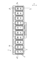
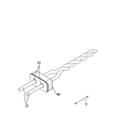
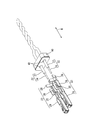
- FIG. 1 An exploded perspective view showing a connector structure according to Embodiment 1.
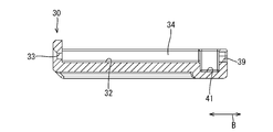
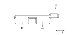
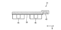
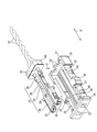
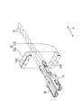
- Sectional view showing the connector structure Perspective view showing the first housing Top view showing the first housing Cross section showing the first housing Side view showing the second housing Cross section showing the second housing Bottom view showing the second housing
- the perspective view which shows the connector for electric wires The perspective view which shows the connector for electric wires Top view showing the wire connector XV-XV sectional view in FIG.
- the connector structure 10 includes a joint connector 11 and a wire connector 12 that can be fitted to the joint connector 11.
- the direction indicated by the arrow A is the vertical direction.
- the fitting direction of the joint connector 11 and the wire connector 12 is taken as the front.
- the front of the fitting direction of the joint connector 11 and the wire connector 12 is used as a reference.
- symbol may be attached to a one part member, and a code
- the joint connector 11 includes a plurality (two in the present embodiment) of joint terminals 13 and a joint connector housing 14 that accommodates the joint terminals 13.
- the joint terminal 13 is formed by pressing a conductive metal plate into a predetermined shape.
- the joint terminal 13 has a plurality (10 in this embodiment) of tabs 15 projecting forward and a base 16 connecting the rear ends of the plurality of tabs 15.
- the joint connector housing 14 is made of insulating synthetic resin, and a plurality of (10 in the present embodiment) connector cavities 17 to which the wire connector 12 housing can be fitted are arranged in the left-right direction, It is formed side by side in the steps.
- the connector cavity 17 is open to the front.
- the cross-sectional shape of the connector cavity 17 has a substantially rectangular shape elongated in the vertical direction. Inside each connector cavity 17, two tabs 15 are arranged side by side at intervals in the vertical direction.
- a lance 18 projecting inward of the cavity is elastically deformable.
- the resilient lance 18 resiliently engages with a lance locking portion 20 of the wire connector housing 19 described later, thereby retaining the wire connector housing 19 in the forward direction.
- two slits 21 opening rearward are formed extending in the left-right direction and aligned vertically.
- the base 16 of the joint terminal 13 is accommodated in each of the slits 21.
- the wire connector 12 has a female terminal 23 (an example of a terminal) connected to an end of the wire 22 and a wire connector housing 19 for housing the female terminal 23.
- the female terminal 23 is formed by pressing a conductive metal plate into a predetermined shape.
- the female terminal 23 includes a bottom wall 25 on which the core wire 24 of the electric wire 22 is mounted, and a wire barrel 26 protruding from both left and right side edges of the bottom wall 25 and crimped to the outer periphery of the core wire 24.
- the wire barrel 26 is crimped to the outer periphery of the core wire 24 so that the electric wire 22 and the female terminal 23 are electrically connected.
- a connection cylindrical portion 29 into which the tab 15 is inserted is formed continuously with the bottom wall 25.
- An elastically deformable tongue (not shown) is formed in the inside of the connection cylindrical portion 29, and when the tongue elastically contacts the tab 15, the joint terminal 13 and the female terminal 23 are electrically connected. Are supposed to be connected.
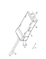
- a plurality of (two in the present embodiment) electric wires 22 are led rearward from the rear end portion of the electric wire connector 12.
- the two electric wires 22 are twisted together after being taken out from the wire connector 12.
- the two wires 22 are so-called twisted pair wires and are used as signal wires.
- the wire connector housing 19 is made of insulating synthetic resin.
- the wire connector housing 19 has a first housing 30 and a second housing 31 integrally assembled to the first housing 30.
- first housing 30 As shown in FIGS. 6 to 8, in the first housing 30, a plurality of (two in the present embodiment) terminal cavities 32 in which the female terminals 23 are accommodated extend in the front-rear direction and are spaced apart from each other. It is formed of In the front wall of each terminal cavity 32, a window hole 33 through which the tab 15 is inserted is formed penetrating the front wall in the front-rear direction.
- the two terminal cavities 32 are separated by a partition wall 34 extending in the front-rear direction.
- the two female terminals 23 are insulated by the partition wall 34.
- An engaging groove 35 extending in the front-rear direction is formed in a recessed manner at the projecting edge of the partition wall 34.
- the engagement groove 35 is engaged with an engagement rib 36 of the first housing 30 described later.
- a locking recess 37 recessed in the opposite direction to the partition wall 34 is formed in the inner wall of the terminal cavity 32.
- the locking concave portion 37 locks the female terminal 23 in the front-rear direction by locking with a locking convex portion 38 which is formed so as to project outward on the outer surface of the connection cylindrical portion 29.
- the bottom walls 25 face each other across the partition wall 34.
- the bottom wall 25 of one female terminal 23 of the two female terminals 23 is located on the other female terminal 23 side
- the bottom wall 25 of the other female terminal 23 is located on the one female terminal 23 side
- An outwardly projecting lance locking portion 20 is formed on the side wall of the first housing 30.
- the lance locking portion 20 locks with the lance 18 described above.
- two grooves 39 are formed side by side at intervals.
- the sectional shape of the groove 39 is the same as or slightly larger than the outer shape of the electric wire 22.
- the electric wire 22 is accommodated in the groove 39.
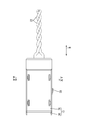
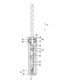
- a first arrangement portion 41 in which the ferrite core 40 can be arranged is formed at a position slightly forward of the rear wall of the first housing 30 and in the area where the electric wire 22 is arranged.
- the ferrite core 40 has a substantially rectangular parallelepiped shape that is flat in the front-rear direction.
- the ridge portion extending in the front-rear direction of the ferrite core 40 is chamfered into a curved surface.
- two insertion holes 42 penetrating in the front-rear direction are formed side by side at intervals.
- the inner diameter of the insertion hole 42 is set to be the same as or slightly larger than the outer diameter of the wire 22.
- the electric wire 22 can be inserted into the insertion hole 42.
- the longitudinal dimension of the first placement portion 41 is set to be equal to or slightly larger than the longitudinal dimension of the ferrite core 40 (see FIG. 16).
- the width dimension of the first placement portion 41 in the direction orthogonal to the front-rear direction is set equal to or slightly larger than the width dimension of the ferrite core 40 in the direction orthogonal to the penetration direction of the insertion hole 42 (see FIG. 21). ).
- the second housing 31 can be assembled to the first housing 30 so as to cover the terminal cavity 32.
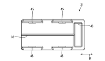
- an engagement rib 36 fitted in the engagement groove 35 of the partition wall 34 of the first housing 30 is formed to extend in the front-rear direction and to project.
- the first housing 30 and the second housing 31 are assembled at the rear end portion of the second housing 31, at a position corresponding to the first arrangement portion 41 of the first housing 30.
- the second arrangement portion 43 is formed.
- the longitudinal dimension of the second placement portion 43 is set to be the same as or slightly larger than the longitudinal dimension of the ferrite core 40.
- the first arrangement portion 41 and the second arrangement portion 43 form an arrangement portion 44 in which the ferrite core 40 can be arranged in the wire connector housing 19.
- An elastically deformable lock portion 45 is formed on the side wall of the second housing 31, and a lock receiving portion 46 engaged with the lock portion 45 at a position corresponding to the lock portion 45 is formed on the side wall of the first housing 30. It protrudes outward and is formed.
- the first housing 30 and the second housing 31 are integrally assembled by resiliently locking the lock portion 45 to the lock receiving portion 46.
- the joint connector 11 is formed by injection molding a synthetic resin.
- the joint terminal 13 is formed by pressing a metal plate material.
- the joint terminal 11 is inserted into the slit 21 of the joint connector 11 from the rear to form the joint connector 11 (see FIG. 1).
- the first housing 30 and the second housing 31 are formed into a predetermined shape by injection molding a synthetic resin.
- the electric wire 22 is inserted into the insertion hole 42 of the ferrite core 40.
- the ends of the electric wires 22 are peeled off to expose the core wire 24.
- wire barrel 26 is crimped to the outer periphery of core wire 24, and insulation barrel 28 is crimped to the outer periphery of insulation coating 27.
- a direction in which the ferrite core 40 is disposed on the outer periphery of the electric wire 22 and the female terminal 23 is connected to the end of the electric wire 22 is shown by the arrow C in the first housing 30. Assemble from.
- the female terminal 23 is accommodated in the terminal cavity 32 of the first housing 30, and the ferrite core 40 is disposed in the first disposition portion 41.
- the second housing 31 is assembled to the first housing 30 in the direction indicated by the arrow C. At this time, a part of the ferrite core 40 is disposed in the second disposition portion 43 of the second housing 31.
- the end of the electric wire 22 is peeled off to expose the core wire 24.
- the wire barrel 26 is crimped to the outer periphery of the core wire 24, and the insulation barrel 28 is crimped to the outer periphery of the insulation coating 27.
- the one in which the female terminal 23 is connected to the end of the wire 22 is assembled to the first housing 30.
- the female terminal 23 is accommodated in the terminal cavity 32 of the first housing 30, and nothing is arranged in the first arrangement portion 41.
- the second housing 31 is assembled to the first housing 30.
- the wire connector 12 in which the ferrite core 40 is disposed and the wire connector 12 in which the ferrite core 40 is not disposed are selectively manufactured.
- the wire connector 12 is fitted in the connector cavity 17 of the joint connector 11. At this time, the wire connector 12 in which the ferrite core 40 is disposed is connected to the tab 15 which needs the noise removal in the high frequency region. On the other hand, the wire connector 12 in which the ferrite core 40 is not disposed is connected to the tab 15 which does not require noise removal in the high frequency region. Thus, the connector structure 10 is completed.
- the connector structure 10 according to the present embodiment can be fitted with the joint connector 11 in which the joint terminal 13 having the base 16 connecting the plurality of tabs 15 is accommodated in the joint connector housing 14, and the joint connector 11,
- a connector structure 10 comprising: a wire connector 12 having a wire connector housing 19 accommodating the female terminal 23 connected to the wire 22, wherein the wire connector housing 19 is a region in which the wire 22 is arranged
- the arrangement portion 44 is capable of arranging the ferrite core 40 on the outer periphery of the electric wire 22.
- the wire connector 12 includes the female terminal 23 connected to the end of the wire 22 and the wire connector housing 19 in which the female terminal 23 is accommodated, and the connector housing includes the wire 22.
- the arrangement portion 44 is capable of arranging the ferrite core 40 on the outer periphery of the electric wire 22 in the area where the wires are arranged.
- the joint connector 11 can be miniaturized. Thereby, the connector structure 10 can be miniaturized as a whole.
- the ferrite core 40 can be selectively disposed in the wire connector housing 19.
- the connector can be configured as compared with the case where the ferrite core 40 is disposed on the outer periphery The cost of the structure 10 can be reduced.
- the wire connector housing 19 has two terminal cavities 32 for receiving two female terminals 23 connected to the respective ends of the two wires 22.
- the ferrite core 40 can be selectively mounted with the wire connector 12 to which the two wires 22 are connected as one unit.
- a signal may flow through the wire 22 containing noise in the high frequency region, and a signal wire through which such a signal is flowed is often a pair of two wires 22.
- the above technique is effective in such a case.
- the wire connector housing 19 is formed by integrally assembling the first housing 30 and the second housing 31.
- the wire connector 12 can be manufactured by a simple method of assembling the first housing 30 and the second housing 31.
- the wire connector housing 19 has two terminal cavities 32 for receiving two female terminals 23 connected to the respective ends of the two wires 22.
- the female terminal 23 is a wire 22 has a bottom wall 25 on which it is mounted, and a wire barrel 26 projecting from the side edge of the bottom wall 25 and crimped to the outer periphery of the electric wire 22, and the female terminal 23 has two terminal cavities 32.
- bottom walls 25 are disposed to face each other.
- bonded by the wire barrel 26 can be closely arranged.
- arranged to the outer periphery of the electric wire 22 can be miniaturized, the connector 12 for electric wires can be miniaturized.
- the ferrite core 50 is formed by combining a pair of half bodies 51A and 51B.
- half body 51A two half groove portions 52A are formed side by side at intervals, and in the half body 51B, two half groove portions 52B are formed side by side at intervals.
- the electric wire 22 is disposed in the gap between the half groove 52A and the half groove 52B in a state where the pair of half members 51A and 51B are combined.
- the step of peeling off the insulation coating 27 of the electric wire 22 and crimping the wire barrel 26 to the exposed core wire 24 is unnecessary.
- the electric wire 22 may be disposed in one half 51A, and then the other half 51B may be assembled. The process can be simplified.
- the two electric wires 22 are drawn out from the electric wire connector 12.
- the present invention is not limited to this.
- One electric wire 22 is connected to the electric wire connector 12
- the configuration may be such that three or more electric wires 22 are connected.
- the female connector 23 is accommodated in the wire connector 12.
- the present invention is not limited to this. Even if the terminals arranged in the wire connector 12 are male terminals Good.
- the two terminals are arranged in a posture in which the bottom walls 25 face each other.
- the present invention is not limited thereto.
- the bottom walls 25 are arranged in the same direction.
- the configuration may be
- the wire connector housing 19 is configured such that the first housing 30 and the second housing 31 are integrally assembled.
- the present invention is not limited thereto. May be.
- the wire connector housing 19 may be configured to assemble three or more members integrally.
- the joint connector 11 includes two joint terminals 13.
- the present invention is not limited to this.
- the joint connector 11 includes one joint terminal 13 or three or more joint terminals 13 It is good also as composition which has.
- connection structure 11 joint connector 12: connector for electric wire 13: joint terminal 14: joint connector housing 15: tab 16: base 19: connector housing for electric wire 22: electric wire 23: female terminal 25: bottom wall 26: wire barrel Reference Signs List 30: first housing 31: second housing 32: terminal cavity 40: ferrite core 41: first arrangement portion 43: second arrangement portion 51A, 51B: half split body
Landscapes
- Details Of Connecting Devices For Male And Female Coupling (AREA)
Abstract
L'invention concerne une structure de connecteur 10 comprenant : un connecteur de jonction 11 obtenu par logement, dans un logement de connecteur de jonction 14, une borne de jonction 13 comprenant une partie de base 16 qui relie une pluralité de languettes 15 ; et un connecteur de fil électrique 12 qui peut être monté sur le connecteur de jonction 11 et qui a un logement de connecteur de fil électrique 19 pour loger des bornes femelles 23 connectées à des fils électriques 22. Le boîtier de connecteur de fil électrique 19 comprend, dans une région dans laquelle les fils électriques 22 sont acheminés, une partie de placement 44 qui permet le placement d'un noyau de ferrite 40 sur la périphérie externe des fils électriques 22.
Applications Claiming Priority (2)
| Application Number | Priority Date | Filing Date | Title |
|---|---|---|---|
| JP2017235966A JP2019102410A (ja) | 2017-12-08 | 2017-12-08 | コネクタ構造体、及び電線用コネクタ |
| JP2017-235966 | 2017-12-08 |
Publications (1)
| Publication Number | Publication Date |
|---|---|
| WO2019111694A1 true WO2019111694A1 (fr) | 2019-06-13 |
Family
ID=66750165
Family Applications (1)
| Application Number | Title | Priority Date | Filing Date |
|---|---|---|---|
| PCT/JP2018/042769 Ceased WO2019111694A1 (fr) | 2017-12-08 | 2018-11-20 | Structure de connecteur et connecteur de fil électrique |
Country Status (2)
| Country | Link |
|---|---|
| JP (1) | JP2019102410A (fr) |
| WO (1) | WO2019111694A1 (fr) |
Families Citing this family (1)
| Publication number | Priority date | Publication date | Assignee | Title |
|---|---|---|---|---|
| JP7817071B2 (ja) * | 2022-04-27 | 2026-02-18 | 矢崎総業株式会社 | コネクタ |
Citations (4)
| Publication number | Priority date | Publication date | Assignee | Title |
|---|---|---|---|---|
| JP2002033153A (ja) * | 2000-04-25 | 2002-01-31 | Thomas & Betts Corp <T&B> | プラグコネクタ |
| JP2003123918A (ja) * | 2001-10-16 | 2003-04-25 | Yazaki Corp | 多重通信用ジョイントコネクタ |
| JP2011082026A (ja) * | 2009-10-07 | 2011-04-21 | Yazaki Corp | コネクタ |
| JP2015149189A (ja) * | 2014-02-06 | 2015-08-20 | 第一精工株式会社 | コネクタ端子 |
-
2017
- 2017-12-08 JP JP2017235966A patent/JP2019102410A/ja active Pending
-
2018
- 2018-11-20 WO PCT/JP2018/042769 patent/WO2019111694A1/fr not_active Ceased
Patent Citations (4)
| Publication number | Priority date | Publication date | Assignee | Title |
|---|---|---|---|---|
| JP2002033153A (ja) * | 2000-04-25 | 2002-01-31 | Thomas & Betts Corp <T&B> | プラグコネクタ |
| JP2003123918A (ja) * | 2001-10-16 | 2003-04-25 | Yazaki Corp | 多重通信用ジョイントコネクタ |
| JP2011082026A (ja) * | 2009-10-07 | 2011-04-21 | Yazaki Corp | コネクタ |
| JP2015149189A (ja) * | 2014-02-06 | 2015-08-20 | 第一精工株式会社 | コネクタ端子 |
Also Published As
| Publication number | Publication date |
|---|---|
| JP2019102410A (ja) | 2019-06-24 |
Similar Documents
| Publication | Publication Date | Title |
|---|---|---|
| JP5563241B2 (ja) | 電気コネクタ | |
| US6361373B1 (en) | Micro miniature electrical connector and method of manufacture | |
| US9379473B2 (en) | Connector | |
| JP4463665B2 (ja) | 防水コネクタ | |
| US9368906B2 (en) | Electric terminal | |
| US8241064B2 (en) | Connector having a body with an reinforcement member fitting into an inwardly bent portion of a shield case | |
| JP2018018703A (ja) | コネクタ | |
| US20150207274A1 (en) | Cable connector assembly with improved grounding structure | |
| JP3117965B2 (ja) | 電気的な差込み結合部材 | |
| JP2001043928A (ja) | 結合コネクタ | |
| JP6894877B2 (ja) | 防水コネクタ | |
| US20070099504A1 (en) | Electrical connector assembly having improved locking mechanism | |
| CN113196585A (zh) | 连接器及连接器结构体 | |
| US20060134949A1 (en) | Electrical connector with protective cover for post header | |
| KR101046855B1 (ko) | 중계 접속 회로 및 중계 커넥터 | |
| JP2015216068A (ja) | コネクタ | |
| JP2001291547A (ja) | 電気コネクタ | |
| JP2013073911A (ja) | ジョイントコネクタ | |
| JP2018005988A (ja) | ジョイントコネクタ、及び、ジョイントコネクタの製造方法 | |
| KR100825244B1 (ko) | 메이팅 커넥터의 삽입 및 분리를 안내해주는 기능이 있는쉘을 가진 커넥터 | |
| JP2019102410A (ja) | コネクタ構造体、及び電線用コネクタ | |
| JP2001357944A (ja) | プラグコネクタ | |
| JP2000067980A (ja) | 2次係止部材付コネクタ及びそれに使用されるハウジング組立体 | |
| JP6865069B2 (ja) | コネクタ | |
| JP2021103653A (ja) | コネクタ |
Legal Events
| Date | Code | Title | Description |
|---|---|---|---|
| 121 | Ep: the epo has been informed by wipo that ep was designated in this application |
Ref document number: 18885273 Country of ref document: EP Kind code of ref document: A1 |
|
| NENP | Non-entry into the national phase |
Ref country code: DE |
|
| 122 | Ep: pct application non-entry in european phase |
Ref document number: 18885273 Country of ref document: EP Kind code of ref document: A1 |