WO2019116414A1 - Appareil d'affichage d'image ultrasonore - Google Patents
Appareil d'affichage d'image ultrasonore Download PDFInfo
- Publication number
- WO2019116414A1 WO2019116414A1 PCT/JP2017/044272 JP2017044272W WO2019116414A1 WO 2019116414 A1 WO2019116414 A1 WO 2019116414A1 JP 2017044272 W JP2017044272 W JP 2017044272W WO 2019116414 A1 WO2019116414 A1 WO 2019116414A1
- Authority
- WO
- WIPO (PCT)
- Prior art keywords
- ultrasonic
- linear transducer
- transducer array
- puncture
- probe
- Prior art date
- Legal status (The legal status is an assumption and is not a legal conclusion. Google has not performed a legal analysis and makes no representation as to the accuracy of the status listed.)
- Ceased
Links
Images







Classifications
-
- A—HUMAN NECESSITIES
- A61—MEDICAL OR VETERINARY SCIENCE; HYGIENE
- A61B—DIAGNOSIS; SURGERY; IDENTIFICATION
- A61B8/00—Diagnosis using ultrasonic, sonic or infrasonic waves
- A61B8/13—Tomography
- A61B8/14—Echo-tomography
Definitions
- the present invention relates to an ultrasonic image display apparatus for acquiring an ultrasonic tomographic image of a subject using an ultrasonic probe and performing puncture while confirming the position of a puncture needle.
- puncturing of a living tissue is widely performed, such as nerve block injection, blood sampling, puncturing and biopsy of deep organs.
- treatment such as nerve block injection or insertion of a catheter
- living tissue may be damaged if puncture is not accurately performed on a target site in a subject.
- an ultrasound guide technology has been proposed in which the target site and the state of the puncture needle are captured using an ultrasonic probe and the puncture is performed while observing them with an ultrasonic tomographic image. .
- one tomographic image is captured using a normal ultrasonic probe (a so-called single plane type probe), and puncturing is performed by displaying this tomographic image.
- a normal ultrasonic probe a so-called single plane type probe
- puncturing is performed by displaying this tomographic image.
- the conventional device it is not possible to simultaneously capture the target site in the subject and the entire surface of the puncture needle. Therefore, there is a problem that it is difficult for the operator to notice even when the puncture needle is not correctly punctured. Therefore, in order to perform accurate puncturing, puncturing must be performed while advancing the puncturing needle little by little while repeating the fine probe operation, and the operation is complicated.
- an ultrasonic probe (so-called bi-plane type probe) capable of simultaneously observing in two orthogonal cross sections in order to simultaneously capture the target site and the entire surface of the puncture needle.
- an ultrasonic image (short axis image and long axis image) of each cross section can be displayed, and the operator observes these two ultrasonic images, It is possible to simultaneously capture the site and the puncture needle.
- a so-called X-type probe 103 in which the two linear transducer arrays 101 and 102 are arranged in an X shape see, for example, Patent Document 2 and FIG. 16
- a so-called T shape It needs to be configured as a T-type probe 104 (see FIG. 17).
- the bi-plane type probe of Patent Document 1 described above is used in an angiographic apparatus, a blood vessel running along a body (upper extremity, lower extremity, etc.) is targeted for puncture. Therefore, puncturing is performed from an oblique direction with respect to the body surface, and the structure is suitable for inserting a puncture needle along a blood vessel which is a target site in the living body.
- the puncture target is, for example, an organ (for example, kidney) or tissue (for example, cyst) in a relatively deep part in the body
- the puncture is not performed from the oblique direction to the body surface, but the puncture is performed from the vertical direction. It is considered desirable to do That is, if puncture is performed in the vertical direction, the puncture needle can reach the target site at the shortest distance from the body surface, which leads to reduction in invasiveness.
- both the X-type probe 103 and the T-type probe 104 described above are suitable for observation and puncture of blood vessels and nerves, the centers of deep organs and deep tissues present independently at specific sites in the body It is unsuitable for observing in two orthogonal cross sections.
- the X-type probe 103 has a structure that seems to be able to obtain an accurate two orthogonal cross sections.
- the X-type probe 103 is configured by the simple linear transducer arrays 101 and 102, there is a fatal problem that any cross section is missing at the intersection of the arrays.
- the puncture needle can not be captured in two orthogonal cross sections and displayed simultaneously on two screens.
- the T-type probe 104 also has the same situation as this.
- the puncture needle and the target site can not be captured and displayed simultaneously in two orthogonal cross sections, and the puncture needle is reliably guided to the target site by the shortest route to Can not collect.
- the inventors of the present application arrange two linear transducer arrays orthogonally on the bottom surface of the probe main body, and incline the ultrasonic wave irradiation surface of one linear transducer array toward the other linear transducer array side.
- positioned is proposed in the past (for example, refer patent document 3).
- the bi-plane type probe of Patent Document 3 is advantageous in that a portion where the ultrasonic beams emitted by the linear transducer array intersect can be used, but has a disadvantage that the configuration tends to be complicated and difficult to manufacture.
- this probe is also basically a T-type probe, it has been difficult to say that it is suitable for vertical puncture applications.
- this configuration of the probe since the inclination angle is determined in advance, there is a disadvantage that the depth of the portion where the ultrasonic beams intersect can not be changed.
- the present invention has been made in view of the above problems, and the object of the present invention is to perform puncturing perpendicular to the surface of a subject relatively early even though the structure is relatively simple.
- An ultrasonic image display apparatus capable of capturing and displaying a puncture needle and a target site in two orthogonal cross sections simultaneously and reliably guiding the puncture needle to the target site by the shortest route.
- the invention according to claim 1 is provided with an ultrasonic probe in which a first linear transducer array and a second linear transducer array are arranged orthogonally on the bottom surface of the probe main body, A first tomographic image showing a first cross section of the subject at the time of puncturing is acquired based on reflected wave data from the subject obtained by transmission and reception of ultrasonic waves using an ultrasonic probe, and An ultrasonic image display apparatus for acquiring a second tomographic image showing a second cross section orthogonal to each other, in a portion where the first linear transducer array and the second linear transducer array intersect in the probe main body, A vacant area in which any linear vibrator array does not exist is provided, and a puncture point for passing a puncture needle at the time of puncture is set in the vacant area, and the first linear vibrator
- the first and second ultrasonic beams are overlapped such that the first ultrasonic beam emitted by B and the second ultrasonic beam emitted by the second linear transducer
- the first ultrasonic beam and the second ultrasonic beam overlap each other directly below the puncture point because the beam steering is performed so as to be inclined toward the vacant area. Do. Therefore, orthogonal tomographic images can be obtained immediately below the puncture point. Therefore, it is possible to capture and simultaneously display the puncture needle and the target portion in two orthogonal cross sections from a relatively early stage when performing a puncture perpendicular to the surface of the subject. Therefore, the puncture needle punctured vertically can be reliably guided to the target site by the shortest route.
- the ultrasonic probe of this device can be configured using a linear transducer array without particularly providing an inclination or the like, the structure can be simplified and manufactured at low cost as compared with the prior art.
- the gist of the invention according to claim 2 is that in claim 1, the beam steering angles of the first and second ultrasonic beams can be changed.
- the depth at which the ultrasonic beams overlap can be adjusted. For this reason, it is possible to set an optimal overlap depth according to a certain depth of the target site (that is, the puncture depth of the puncture needle).
- the invention according to claim 3 is characterized in that, in claim 1, the beam steering angles of the first and second ultrasonic beams can be changed at the same time by equal angles.
- the control can be performed collectively and easily compared to the control for changing the beam steering angles of the two ultrasonic beams individually, and thus the linear used It can also contribute to the simplification of the transducer array.
- the first to x-th (wherein x is a natural number of 3 or more and N-3 or less)
- the second part including the (x + 1) -th to N-th transducers
- the first part is used as the first linear transducer array
- the second part is The first part and the first part are used as a second linear transducer array, with the x-th transducer side of the first part and the N-th transducer side of the second part directed to the vacant area.
- the point is that the second part is placed.
- the invention according to a fifth aspect is the method according to the fourth aspect, wherein the number of the transducers belonging to the first part used as the first linear transducer array and the second part used as the second linear transducer array
- the gist of the present invention is that the number of the transducers belonging to is approximately equal.
- the number of transducers is approximately equal between the first linear transducer array and the second linear transducer array, the beam steering angles of two ultrasonic beams are simultaneously equal. It becomes easy to control changing by angle.
- the shape of the deep organ or deep tissue which is the target site is unknown, etc. It will be advantageous.
- the invention according to claim 6 is the puncture guide portion for guiding the puncture needle to the puncture point in a portion corresponding to the empty area in the probe main body according to any one of claims 1 to 5 according to any one of claims 1 to 5 Its gist is that it is provided.
- the puncture needle being guided by the puncture guide portion, it is possible to puncture the subject easily and accurately.
- the puncture guide portion guides a guide hole for guiding the puncture needle so that the puncture needle advances in a direction perpendicular to the bottom surface of the probe main body. The point is to have it.
- the puncture needle since the puncture needle is reliably guided in the vertical direction by the guide hole, the puncture needle can reach the target region of the subject at the shortest distance.
- FIG. 2 is a perspective view showing a probe main body of the ultrasonic probe in the present embodiment.
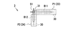
- the bottom view which shows the probe main part of the ultrasonic probe in this embodiment.
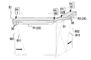
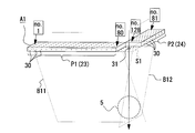
- FIG. 5 is a schematic view for explaining the configuration of a first linear transducer array and a second linear transducer array in the probe main body.
- FIG. 5 is a schematic view for explaining the configuration of a first linear transducer array and a second linear transducer array in the probe main body.
- FIG. 5 is a schematic view for explaining the configuration of a first linear transducer array and a second linear transducer array in the probe main body.
- FIG. 5 is a schematic view for explaining the configuration of a first linear transducer array and a second linear transducer array in the probe main body.
- FIG. 5 is a schematic view for explaining the configuration of a first linear transducer array and a second linear transducer array in the probe main body.
- Explanatory drawing which shows the ultrasound image (state before puncturing) of the orthogonal two cross section in this embodiment.
- Explanatory drawing which shows the ultrasound image (state after puncturing) of the orthogonal two cross section in this embodiment.
- FIG. 5 is a schematic view for explaining the arrangement of a first linear transducer array and a second linear transducer array in the present embodiment.
- FIG. 7 is a schematic view for explaining the arrangement of a first linear transducer array and a second linear transducer array in another embodiment.
- FIG. 7 is a schematic view for explaining the arrangement of a first linear transducer array and a second linear transducer array in another embodiment.
- FIG. 7 is a schematic view for explaining the arrangement of a first linear transducer array and a second linear transducer array in another embodiment.
- FIG. 8 is a schematic view for explaining the arrangement of a first linear transducer array and a second linear transducer array in the prior art.
- FIG. 8 is a schematic view for explaining the arrangement of a first linear transducer array and a second linear transducer array in the prior art.
- FIG. 1 is an overall schematic view showing an apparatus 1 of the present embodiment
- FIG. 2 is a block diagram showing an electrical configuration of the apparatus 1.
- the deep organ puncturing apparatus 1 of the present embodiment includes an apparatus main body 2 and an ultrasonic probe 3 connected to the apparatus main body 2.
- the deep organ puncturing apparatus 1 is used, for example, when inserting the puncture needle 6 into a target site 5 (for example, a deep organ such as a kidney or a deep tissue such as a cyst or a tumor) in a living tissue 4 (subject). Ru.
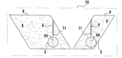
- the deep organ puncturing apparatus 1 has the same screen 10 of a first tomographic image 8 showing a first cross section of the puncture needle 6 and the target site 5 and a second tomographic image 9 showing a second cross section orthogonal to the first cross section. It is simultaneously displayed on top (see FIGS. 9 to 11).
- the ultrasonic probe 3 has a signal cable 11, a probe main body 12 connected to the tip of the signal cable 11, and a probe side provided at the base end of the signal cable 11. And a connector 15. Further, as shown in FIG. 2, the apparatus main body 2 is provided with a connector 16, and the probe-side connector 15 of the ultrasonic probe 3 is connected to the connector 16.
- the ultrasonic probe 3 is a linear probe for performing linear electronic scanning, and linearly scans, for example, 5 MHz ultrasonic waves.
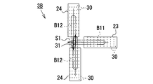
- the first linear transducer array 23 and the second linear transducer array 24 are orthogonally arranged on the bottom surface 20 of the probe main body 12 so as to form a substantially L-shape.
- the first linear transducer array 23 is for acquiring the first tomographic image 8 and linearly aligns the plurality of transducers along the first direction X (ie, the direction corresponding to the first cross section). It is comprised by arranging.
- the second linear transducer array 24 is for acquiring the second tomographic image 9, and linearly aligns the plurality of transducers 30 along the second direction Y (that is, the direction corresponding to the second cross section).
- the number of elements of the transducers 30 constituting the first linear transducer array 23 is, for example, 80, and the number of elements of the transducers 30 constituting the second linear transducer array 24 is more than that.
- the number is small (for example, 48). Accordingly, the length of the first linear transducer array 23 in the arrangement direction is longer than the length of the second linear transducer array 24 in the arrangement direction.
- the two linear transducer arrays 23 and 24 in the present embodiment are originally derived from one linear transducer array A1 (see FIG. 5). More specifically, if it is a linear transducer array A1 having N transducers 30, the linear transducer array A1 is divided into a first part P1 and a second part P2, which are 90 ° It is bent and arranged in a substantially L shape (see FIG. 6). Incidentally, the first part P1 is a part used as the first linear transducer array 23, and the second part P2 is a part used as the second linear transducer array 24. At this time, at the intersection of the first linear transducer array 23 and the second linear transducer array 24 on the bottom surface 20 of the probe main body 12, an empty area S1 in which none of the linear transducer arrays 23 and 24 exist is provided. Be
- the two parts P2 include the (x + 1) th to the Nth vibrators 30 (here, the 81st to the 128th).
- the first part P1 and the second part P2 are arranged with the 80th vibrator 30 side of the first part P1 and the 128th vibrator 30 side of the second part P2 directed to the vacant area S1. ing.
- ultrasound scanning is performed one by one from the first transducer 30 to the 128th transducer 30 in order. Specifically, first, ultrasound scanning is performed from one end of the first part P1 used as the first linear transducer array 23 to the other end (that is, the free space side end). Then, in succession to this, ultrasonic scanning is performed from one end of the second part P2 used as the second linear transducer array 24 to the other end (that is, the empty area side end).
- the bottom surface 20 of the probe main body 12 is a surface in contact with the living tissue 4, and this is a transmission / reception surface for transmitting / receiving ultrasonic waves.
- An acoustic lens 29 is disposed on the bottom surface 20 of the probe main body 12 so as to cover the linear transducer arrays 23 and 24 via an acoustic matching layer (not shown).
- the acoustic lens 29 is made of, for example, a silicone resin, and has a convex surface whose outer surface in contact with the living tissue 4 is curved.
- this acoustic lens 29 plays a role of narrowing down the beam of the ultrasonic wave output in the normal direction from the ultrasonic wave emitting surface of the linear transducer array 23, 24 and converging it at a predetermined focal position. Plays.
- a backing material (not shown) for preventing the propagation of ultrasonic waves to the rear is disposed on the side opposite to the ultrasonic radiation surface in the linear transducer arrays 23 and 24.
- a puncture guide portion 34 for guiding the puncture needle 6 to the puncture point 31 is provided at a position corresponding to the vacant area S1 in the probe main body 12.
- the puncture guide portion 34 of the present embodiment is a block-shaped portion protruding from the lower side surface of the probe main body 12, and has guide holes H1 vertically penetrating the upper end surface and the lower end surface of the portion. There is.
- the guide hole H1 is disposed corresponding to the puncture point 31 and serves to guide the puncture needle 6 so that the puncture needle 6 advances in a direction perpendicular to the bottom surface 20 of the probe main body 12.
- the device main body 2 of the deep organ lancing apparatus 1 includes a controller 50, a pulse generation circuit 51, a transmission circuit 52, a reception circuit 53, a signal processing unit 54, an image processing unit 55, a memory 56, and a storage device. 57, an input device 58, a display device 59, a steering angle control unit 81, and the like.
- the controller 50 is a computer configured to include a well-known central processing unit (CPU), executes a control program using the memory 56, and centrally controls the entire apparatus.
- CPU central processing unit
- the pulse generation circuit 51 operates in response to the control signal from the controller 50, and generates and outputs a pulse signal of a predetermined cycle.
- the transmission circuit 52 includes a delay circuit 52 a corresponding to the number of elements of the linear transducer arrays 23 and 24 in the ultrasonic probe 3, and each linear transducer array 23, based on the pulse signal output from the pulse generation circuit 51, The drive pulse delayed according to 24 is output.
- the delay circuit 52a of this embodiment sets a delay amount for performing a predetermined beam focusing, and a second delay circuit for setting a delay amount for performing a predetermined beam focusing. And a delay circuit unit.
- the delay amount of each drive pulse is set such that the ultrasonic beams B11 and B12 emitted from the respective linear transducer arrays 23 and 24 in the ultrasonic probe 3 are focused at predetermined irradiation points. It is done.
- the present embodiment is as follows. That is, for the first linear transducer array 23, the delay amount of the first transducer 30 and the 80th transducer 30 located at the outermost position is set to be the smallest. The amount of delay is set to gradually increase as it goes to the 40th vibrator 30 located substantially at the center. In the second linear transducer array 24, the delay amount of the 81st transducer 30 and the 128th transducer 30 located at the outermost position is set to be the smallest. The amount of delay is set to gradually increase as it goes to the 104th vibrator 30 located substantially at the center.
- the ultrasonic beams B11 and B12 emitted from the linear transducer arrays 23 and 24 of the ultrasonic probe 3 are respectively inclined in the direction of the vacant area S1 (that is, electronically steered To set the delay amount of each drive pulse (see FIGS. 7 and 8).
- the present embodiment is as follows. That is, for the first linear transducer array 23, the delay amount of the first transducer 30 located farthest from the vacant area S1 is set to be the smallest. The delay amount is set to gradually increase as it goes to the 80th vibrator 30 located closest to the free space S1.
- the delay amount of the 81st transducer 30 located farthest from the vacant area S1 is set to be the smallest.
- the delay amount is set to gradually increase as it goes to the 128th vibrator 30 located closest to the vacant area S1.
- the first ultrasonic beam B11 emitted by the first linear transducer array 23 and the second ultrasonic beam B12 emitted by the second linear transducer array 24 are directly below the puncture point 31. Are designed to overlap each other.
- the ultrasonic beams B01 and B02 before steering are also shown for comparison.
- the receiving circuit 53 includes a signal amplification circuit (not shown), an A / D conversion circuit, a delay circuit 53a, and a phasing addition circuit.
- each reflected wave signal (echo signal) received by each linear transducer array 23, 24 in the ultrasonic probe 3 is amplified, and an analog signal is converted into a digital signal, and further, the reception directivity is After the considered delay amount is added to each reflected wave signal, phasing addition is performed. By this addition, the phase difference between the reception signals of the linear transducer arrays 23 and 24 is adjusted.
- the delay circuit 53a of this embodiment sets the delay amount in consideration of the beam focus
- the second delay circuit sets the delay amount in consideration of the beam steering. It is composed of parts. Specifically, in the first delay circuit unit, the same delay amount as that of the first delay circuit unit in the delay circuit 52a of the transmission circuit 52 is set. Further, in the second delay circuit unit, the same delay amount as that of the second delay circuit unit in the delay circuit 52a of the transmission circuit 52 is set.
- the signal processing unit 54 is composed of a logarithmic conversion circuit (not shown), an envelope detection circuit, etc., and data (B mode) in which the signal intensity is expressed by the brightness of luminance based on the reflected wave signal data from the receiving circuit 53. Generate data).
- the logarithmic conversion circuit logarithmically converts the reflected wave signal
- the envelope detection circuit detects the envelope of the output signal of the logarithmic conversion circuit.
- the image processing unit 55 performs predetermined image processing based on the B mode data generated by the signal processing unit 54, and generates a B mode ultrasonic image (tomographic image). Specifically, the image processing unit 55 generates image data of luminance according to the amplitude (signal strength) of the reflected wave signal. The data of the image generated by the image processing unit 55 is sequentially stored in the memory 56. Here, image data of a first tomographic image 8 showing a first cross section of the living tissue 4 and image data of a second tomographic image 9 showing a second cross section of the living tissue 4 are generated and stored in the memory 56. Then, based on the image data of one frame stored in the memory 56, the first tomographic image 8 and the second tomographic image 9 of the living tissue 4 are displayed on the display device 59 in black and white (see FIGS. 9 and 10). 11).
- the input device 58 is configured of a keyboard 61, a track ball 62, and the like, and is used to input a request or an instruction from a user.
- the display device 59 is, for example, a display such as an LCD or a CRT, and is used to display the first tomographic image 8 and the second tomographic image 9 of the living tissue 4 and an input screen of various settings.
- the first tomographic image 8 and the second tomographic image 9 are simultaneously displayed side by side on the screen 10 of the display device 59 of the present embodiment.
- the first tomographic image 8 exhibits a parallelogram shape inclined to the left
- the second tomographic image 9 exhibits a parallelogram shape inclined to the right.
- a guide line 65 extending linearly along the screen vertical direction is displayed.
- the guide line 65 is used to indicate the direction in which the puncture needle 6 moves, and starts from the right oblique side of the parallelogram-shaped first tomographic image 8 and ends from the bottom.
- a guide line 66 linearly extending along the screen vertical direction is displayed.
- the guide line 66 is used to indicate the direction in which the puncture needle 6 moves, and starts from the left oblique side of the parallelogram-like second tomographic image 9 and ends from the bottom.
- the steering angle control unit 81 is connected to the delay circuit 52a of the transmission circuit 52, and adjusts the steering angle of the first ultrasonic beam B11 based on an instruction from the controller 50. Take control. More specifically, in the transmission circuit 52, the steering angle control unit 81 changes the delay amount in the second delay circuit unit of the delay circuit 52a. For example, for the first linear transducer array 23, the steering angle of the first ultrasonic beam B11 is reduced by reducing the difference between the delay amount of the first transducer 30 and the delay amount of the 80th transducer 30. Can be made smaller.
- FIG. 11 shows a state in which the steering angles of the ultrasonic beams B11 and B12 are changed to be smaller than those in FIGS. 9 and 10. Also in the receiving circuit 53, basically the same steering angle control as described above is performed.
- the depth at which the ultrasonic beams B11 and B12 overlap with each other can be adjusted.
- an optimal overlap depth in accordance with a certain depth of the target portion 5. For example, in FIGS. 9 and 10 described above, since the beam steering angle is relatively large, the overlap depth is set to be shallow. On the other hand, in FIG. 11, since the beam steering angle is relatively small, the overlap depth is set to be deep.
- the beam steering angles of the first and second ultrasonic beams B11 and B12 may be changed simultaneously at the same angle, or may be simultaneously changed at different angles. Further, the beam steering angle can be changed, for example, using the above-described input device 58.
- the storage device 57 is a magnetic disk device, an optical disk device, or the like, and stores the control program and various data in a recording medium.
- the controller 50 transfers programs and data from the storage device 57 to the memory 56 in accordance with instructions from the input device 58, and sequentially executes them.
- the program executed by the controller 50 may be a program stored in a storage medium such as a memory card, a flexible disk (FD), a CD-ROM, a DVD, an optical disk, or a program downloaded via a communication medium. At the time of execution, it is installed in the storage device 57 and used.
- an operator such as a doctor applies an acoustic medium (sterile gel or sterile gel) to the surface of the living tissue 4 to be treated, and then brings the bottom surface 20 of the probe main body 12 into contact via the acoustic medium. Thereafter, the operator operates a scan start button (not shown) provided on the input device 58. Then, the controller 50 determines the button operation and starts processing for displaying the tomographic images 8 and 9 of the living tissue 4.
- a scan start button not shown
- the controller 50 operates the pulse generation circuit 51 to start transmission and reception of ultrasonic waves by the ultrasonic probe 3.
- the pulse generation circuit 51 operates in response to the control signal output from the controller 50, and a pulse signal of a predetermined cycle is supplied to the transmission circuit 52.
- drive pulses having delay times corresponding to the ultrasonic transducers 23 and 24 are generated based on the pulse signals, and supplied to the ultrasonic probe 3.
- the linear transducer arrays 23 and 24 of the ultrasonic probe 3 vibrate and ultrasonic waves are emitted toward the living tissue 4.
- the reflected wave from the living tissue 4 is received by each of the linear transducer arrays 23, 24, and converted into an electrical signal (reflected wave signal).
- the reflected wave signal is amplified and A / D converted by the receiving circuit 53, and then input to the signal processing unit 54.
- the signal processing unit 54 performs signal processing such as logarithmic conversion and envelope detection on the reflected wave signal.
- the image processing unit 55 performs image processing for generating image data of the tomographic images 8 and 9 based on the reflected wave signal. Then, the controller 50 temporarily stores each image data generated by the image processing unit 55 in the memory 56.
- the controller 50 reads each image data stored in the memory 56, and generates display data for causing the display device 59 to display the first tomographic image 8 and the second tomographic image 9. Further, the controller 50 as a guideline display means generates display data of the guidelines 65 and 66.
- the controller 50 outputs the generated display data of the tomographic images 8 and 9 and the guidelines 65 and 66 to the display device 59, respectively.
- the first tomographic image 8 and the second tomographic image 9 are simultaneously displayed side by side on the screen 10 of the display device 59.
- the guidelines 65 and 66 are superimposed and displayed.
- the operator adjusts the position of the ultrasonic probe 3 while visually recognizing the first tomographic image 8 and the second tomographic image 9 displayed on the display device 59.
- the first linear vibration of the ultrasonic probe 3 is made so that the cross section of the target portion 5 is displayed on the first tomographic image 8 and the first guide line 65 is positioned substantially at the center of the target portion 5.
- the second linear transducer array 24 of the ultrasonic probe 3 is displayed so that the cross section of the target site 5 is displayed on the second tomographic image 9 and the second guide
- the operator inserts the puncture needle 6 into the guide hole H1 of the puncture guide portion 34 from the upper end surface side of the puncture guide portion 34.
- the puncture needle 6 is pushed downward, the tip 71 of the puncture needle 6 reaches the puncture point 31, and when the puncture needle 6 is further pushed downward, the bottom surface 20 of the probe main body 12 )
- the puncture needle 6 is guided such that the puncture needle 6 advances in the vertical direction.
- the first tomographic image 8 and the second tomographic image 9 since the guidelines 65 and 66 are displayed in advance, the puncture can be performed while confirming the advancing direction of the puncture needle 6.
- the operator stops the operation of pushing the puncture needle 6. Then, processing (for example, injection of a drug solution through the puncture needle 6, collection of tissue, etc.) to the target site 5 is performed as necessary in this state.
- the controller 50 determines the button operation, and ends the processing for displaying the tomographic images 8 and 9 of the living tissue 4.
- a vacant area S1 is provided in the portion where the first and second linear transducer arrays 23, 24 intersect in the probe main body 12, and the puncture point 31 is set there. ing. Then, the first ultrasonic beam B11 emitted from the first linear transducer array 23 and the second ultrasonic beam B12 emitted from the second linear transducer array 24 are electronically steered such that they are each inclined in the direction of the vacant area S1. It is done. As a result of such beam steering, the first ultrasonic beam B11 and the second ultrasonic beam B12 overlap each other immediately below the puncture point 31.
- orthogonal tomographic images 8 and 9 can be reliably obtained immediately below the puncture point 31. Therefore, it is possible to capture and simultaneously display the puncture needle 6 and the target site 5 in two orthogonal cross sections from a relatively early stage when performing a puncture perpendicular to the surface of the subject 4. Therefore, the puncture needle 6 punctured vertically can be reliably guided to the target site 5 by the shortest route.
- the deep organ puncturing apparatus 1 of the present embodiment since the puncture needle 6 and the target site 5 (deep organ) can always be observed in two orthogonal cross sections, surrounding tissues are damaged under ultrasound guidance. The puncture can be performed easily and reliably.
- the use of the deep organ puncturing apparatus 1 has the advantage that it leads to shortening of the diagnosis and treatment time for the operator and also has the merit of reducing the invasiveness to the subject (patient).
- the ultrasonic probe 3 of the present embodiment can be configured using the linear transducer arrays 23 and 24 without particularly providing an inclination or the like. Therefore, the structure can be simplified as compared with the prior art in which the ultrasonic wave irradiation surface of one linear transducer array of the two linear transducer arrays arranged orthogonal to each other is inclined to the other side, It can be manufactured inexpensively. Furthermore, while the above-mentioned prior art in which the inclination angle is determined in advance has the disadvantage that the depth etc. of the portion where the ultrasonic beams intersect can not be changed, according to this ultrasonic probe 3, the ultrasonic beam B11 The depth can be changed relatively easily by adjusting the steering angle of B12.
- the deep organ puncture device 1 of the present embodiment includes the steering angle control unit 81, so that the beam steering angles of the first and second ultrasonic beams B11 and B12 can be changed. ing. Therefore, the depth at which the ultrasonic beams B11 and B12 overlap with each other can be appropriately adjusted. For this reason, it is possible to set an optimal overlap depth according to a certain depth of the target site 5 (that is, the puncture depth of the puncture needle 6). Specifically, when the target portion 5 is at a relatively shallow position, as shown in FIGS. 9 and 10, the steering angles of the ultrasonic beams B11 and B12 are adjusted to be larger. In this case, the ultrasonic beams B11 and B12 overlap at relatively shallow positions.
- the puncture needle 6 can be captured in two orthogonal cross sections and displayed simultaneously from an earlier stage (that is, a depth position very close to the body surface).
- the steering angles of the ultrasonic beams B11 and B12 are adjusted to be smaller. In this case, the ultrasonic beams B11 and B12 overlap at relatively deep positions.
- one linear transducer array A1 is used as a starting material. Then, this is divided into a first part P1 including the first to 80th vibrators 30 and a second part P2 including the 81st to 128th vibrators 30, respectively, whereby the first linear vibrator array is obtained.
- the second linear transducer array 24 is used.
- the first part P1 and the second part P2 are arranged with the 80th vibrator 30 side of the first part P1 and the 128th vibrator 30 side of the second part P2 directed to the vacant area S1. It is like that.
- the beam steering angles of the two ultrasonic beams B11 and B12 can be changed at the same time and with equal angles relatively easily without requiring special processing and the like.
- a puncture guide 34 for guiding the puncture needle 6 to the puncture point 31 is provided at a location corresponding to the free space S1 in the probe main body 12 .
- the puncture guide portion 34 is provided with a guide hole H1 for guiding the puncture needle 6 so that the puncture 6 needle advances in a direction perpendicular to the bottom surface 20 of the probe main body 12. Therefore, the puncture needle 6 is reliably guided in the vertical direction by the guide hole H1 of the puncture guide portion 34. As a result, the puncture needle 6 can be easily and accurately reached at the shortest distance to the target site 5 of the subject 4.
- the number of oscillators (80) is larger than that of the other oscillator (48).
- the number of transducers in the first part P1 and the number of transducers in the second part P2 are made the same (for example, 64). May be With such a configuration, there is an advantage that it is easy to control to change the beam steering angles of the two ultrasonic beams B11 and B12 simultaneously at the same angle.
- the total element number N of the linear vibrator array A1 as a starting material is not limited to 128, and may be more or less than this.
- the first part P1 and the second part P2 originally derived from one linear transducer array A1 are used as the first linear transducer array 23 and the second linear transducer array 24, but It is not limited.
- the ultrasonic probe 3 may of course be configured using two separate linear transducer arrays from the beginning.
- the first linear transducer array 23 and the second linear transducer array 24 are arranged in a substantially L shape on the bottom surface 20 of the probe main body 12 to make them orthogonal to each other. Not limited to this.
- the first linear transducer array 23 and the second linear transducer array 24 are arranged in a substantially square shape so that they are orthogonal to each other. You can also In FIG. 15, the puncture points 31 are formed in two places.
- the guide hole H1 is provided in the puncture guide portion 34 for guiding the puncture needle 6 to the puncture point 31, but the invention is not limited thereto.
- a structure such as a guide groove may be used.
- the puncture guide 34 may not necessarily be in a block shape.
- the guidelines 65 and 66 are displayed on the first tomographic image 8 and the second tomographic image 8, respectively, but such a display may be omitted.
- the ultrasound image display apparatus of this invention was embodied as the deep organ puncture apparatus 1 in the said embodiment, it is not limited to this. That is, since the puncture target is not necessarily deep organ, for example, deep tissue may be used, and the present invention may be embodied as a deep tissue puncture device.
Landscapes
- Life Sciences & Earth Sciences (AREA)
- Health & Medical Sciences (AREA)
- Biomedical Technology (AREA)
- Biophysics (AREA)
- Nuclear Medicine, Radiotherapy & Molecular Imaging (AREA)
- Pathology (AREA)
- Radiology & Medical Imaging (AREA)
- Engineering & Computer Science (AREA)
- Physics & Mathematics (AREA)
- Heart & Thoracic Surgery (AREA)
- Medical Informatics (AREA)
- Molecular Biology (AREA)
- Surgery (AREA)
- Animal Behavior & Ethology (AREA)
- General Health & Medical Sciences (AREA)
- Public Health (AREA)
- Veterinary Medicine (AREA)
- Ultra Sonic Daignosis Equipment (AREA)
Abstract
La présente invention a une structure relativement simple, permet de capturer des images d'une aiguille de ponction et d'un site cible dans deux sections transversales perpendiculaires et de réaliser un affichage de celles-ci simultanément dans un stade relativement précoce lorsqu'une ponction verticale est effectuée sur un patient, et guide de façon sûre l'aiguille de ponction vers le site cible dans le trajet le plus court. Dans un corps de sonde (12), des premier et second réseaux d'oscillateurs linéaires (23, 24) sont disposés perpendiculairement l'un par rapport à l'autre. Une zone vide (S1) est disposée dans une partie où les deux réseaux d'oscillateurs linéaires (23, 24) se croisent mutuellement dans le corps de sonde (12). Dans la zone vide (en S1), un point de ponction (31) est défini pour laisser passer une aiguille de ponction 6. Le premier réseau d'oscillateurs linéaires (23) émet un premier faisceau ultrasonore (B11), et le second réseau d'oscillateurs linéaires (24) émet un second faisceau ultrasonore (B12). Les deux faisceaux ultrasonores (B11, B12) sont orientés électroniquement pour être inclinés vers une direction de la zone vide (S1). Par conséquent, les deux faisceaux ultrasonores (B11, B12) se chevauchent directement au-dessous du point de ponction (31).
Priority Applications (2)
| Application Number | Priority Date | Filing Date | Title |
|---|---|---|---|
| JP2018517901A JP6379363B1 (ja) | 2017-12-11 | 2017-12-11 | 超音波画像表示装置 |
| PCT/JP2017/044272 WO2019116414A1 (fr) | 2017-12-11 | 2017-12-11 | Appareil d'affichage d'image ultrasonore |
Applications Claiming Priority (1)
| Application Number | Priority Date | Filing Date | Title |
|---|---|---|---|
| PCT/JP2017/044272 WO2019116414A1 (fr) | 2017-12-11 | 2017-12-11 | Appareil d'affichage d'image ultrasonore |
Publications (1)
| Publication Number | Publication Date |
|---|---|
| WO2019116414A1 true WO2019116414A1 (fr) | 2019-06-20 |
Family
ID=63354695
Family Applications (1)
| Application Number | Title | Priority Date | Filing Date |
|---|---|---|---|
| PCT/JP2017/044272 Ceased WO2019116414A1 (fr) | 2017-12-11 | 2017-12-11 | Appareil d'affichage d'image ultrasonore |
Country Status (2)
| Country | Link |
|---|---|
| JP (1) | JP6379363B1 (fr) |
| WO (1) | WO2019116414A1 (fr) |
Cited By (2)
| Publication number | Priority date | Publication date | Assignee | Title |
|---|---|---|---|---|
| CN114199998A (zh) * | 2020-09-18 | 2022-03-18 | 宝山钢铁股份有限公司 | 用于焊管坡口未熔合和夹渣缺陷的手动检测方法及装置 |
| US12611178B2 (en) * | 2023-11-30 | 2026-04-28 | Wuhan United Imaging Healthcare Co., Ltd. | Ultrasonic probe and ultrasonic device incorporating different arrays |
Families Citing this family (1)
| Publication number | Priority date | Publication date | Assignee | Title |
|---|---|---|---|---|
| JP2023107256A (ja) * | 2022-01-22 | 2023-08-03 | 株式会社ユネクス | 穿刺針位置表示装置 |
Citations (3)
| Publication number | Priority date | Publication date | Assignee | Title |
|---|---|---|---|---|
| JPH0595945A (ja) * | 1991-10-08 | 1993-04-20 | Toshiba Corp | 穿刺用超音波プローブ |
| JPH05317309A (ja) * | 1992-05-21 | 1993-12-03 | Hitachi Medical Corp | 穿刺用超音波探触子 |
| JP2000201936A (ja) * | 1998-05-07 | 2000-07-25 | Diasonics Ultrasound Inc | 2平面超音波イメ―ジング方法及び装置 |
Family Cites Families (2)
| Publication number | Priority date | Publication date | Assignee | Title |
|---|---|---|---|---|
| US7806828B2 (en) * | 2002-02-05 | 2010-10-05 | Inceptio Medical Technologies, Lc | Multiplanar ultrasonic vascular sensor assembly and apparatus for movably affixing a sensor assembly to a body |
| US10806486B2 (en) * | 2015-08-31 | 2020-10-20 | Neda Buljubasic | Systems and methods for providing ultrasound guidance to target structures within a body |
-
2017
- 2017-12-11 WO PCT/JP2017/044272 patent/WO2019116414A1/fr not_active Ceased
- 2017-12-11 JP JP2018517901A patent/JP6379363B1/ja active Active
Patent Citations (3)
| Publication number | Priority date | Publication date | Assignee | Title |
|---|---|---|---|---|
| JPH0595945A (ja) * | 1991-10-08 | 1993-04-20 | Toshiba Corp | 穿刺用超音波プローブ |
| JPH05317309A (ja) * | 1992-05-21 | 1993-12-03 | Hitachi Medical Corp | 穿刺用超音波探触子 |
| JP2000201936A (ja) * | 1998-05-07 | 2000-07-25 | Diasonics Ultrasound Inc | 2平面超音波イメ―ジング方法及び装置 |
Cited By (3)
| Publication number | Priority date | Publication date | Assignee | Title |
|---|---|---|---|---|
| CN114199998A (zh) * | 2020-09-18 | 2022-03-18 | 宝山钢铁股份有限公司 | 用于焊管坡口未熔合和夹渣缺陷的手动检测方法及装置 |
| CN114199998B (zh) * | 2020-09-18 | 2024-03-08 | 宝山钢铁股份有限公司 | 用于焊管坡口未熔合和夹渣缺陷的手动检测方法及装置 |
| US12611178B2 (en) * | 2023-11-30 | 2026-04-28 | Wuhan United Imaging Healthcare Co., Ltd. | Ultrasonic probe and ultrasonic device incorporating different arrays |
Also Published As
| Publication number | Publication date |
|---|---|
| JP6379363B1 (ja) | 2018-08-29 |
| JPWO2019116414A1 (ja) | 2019-12-19 |
Similar Documents
| Publication | Publication Date | Title |
|---|---|---|
| JP5337782B2 (ja) | 超音波診断装置 | |
| JP5435751B2 (ja) | 超音波診断装置、超音波送受信方法、および超音波送受信プログラム | |
| JP5976441B2 (ja) | 超音波プローブ及び超音波診断装置 | |
| US11324478B2 (en) | Ultrasound diagnostic apparatus and ultrasound image display method | |
| JP6019369B1 (ja) | 超音波画像表示装置及びその作動方法、並びにプログラムを格納した記録媒体 | |
| JP2007159653A (ja) | 穿刺用超音波プローブ及び超音波診断装置 | |
| EP2039297B1 (fr) | Appareil de diagnostic à ultrasons | |
| JP6334992B2 (ja) | 可搬型超音波診断装置 | |
| JP6379363B1 (ja) | 超音波画像表示装置 | |
| JP5475971B2 (ja) | 超音波診断装置 | |
| JP6933031B2 (ja) | 超音波探触子及び超音波診断装置 | |
| JP2010088486A (ja) | 超音波診断装置 | |
| WO2019058753A1 (fr) | Dispositif de diagnostic par ultrasons et procédé de commande de dispositif de diagnostic par ultrasons | |
| CN103356237B (zh) | 超声波诊断装置以及控制方法 | |
| JP2003093389A (ja) | 超音波診断装置 | |
| JP6714927B2 (ja) | 超音波画像表示装置及び方法、並びにプログラムを格納した記録媒体 | |
| JP6078732B1 (ja) | 超音波プローブ | |
| JP6484781B1 (ja) | 超音波画像表示装置 | |
| CN101711685A (zh) | 体腔用超声波探头及超声波诊断装置 | |
| WO2022244552A1 (fr) | Dispositif de diagnostic ultrasonore et procédé de commande de dispositif de diagnostic ultrasonore | |
| JP2005168768A (ja) | 超音波画像診断装置 | |
| CN113017787B (zh) | 超声波探头、超声波图像显示装置 | |
| JP2018531717A (ja) | 神経ブロックで使用するための3次元超音波撮像システム | |
| JP7576828B2 (ja) | 超音波画像表示装置 | |
| CN120051319A (zh) | Hifu照射装置以及焦点调整方法 |
Legal Events
| Date | Code | Title | Description |
|---|---|---|---|
| ENP | Entry into the national phase |
Ref document number: 2018517901 Country of ref document: JP Kind code of ref document: A |
|
| 121 | Ep: the epo has been informed by wipo that ep was designated in this application |
Ref document number: 17934812 Country of ref document: EP Kind code of ref document: A1 |
|
| NENP | Non-entry into the national phase |
Ref country code: DE |
|
| 122 | Ep: pct application non-entry in european phase |
Ref document number: 17934812 Country of ref document: EP Kind code of ref document: A1 |