WO2019116434A1 - Dispositif de type moteur - Google Patents
Dispositif de type moteur Download PDFInfo
- Publication number
- WO2019116434A1 WO2019116434A1 PCT/JP2017/044444 JP2017044444W WO2019116434A1 WO 2019116434 A1 WO2019116434 A1 WO 2019116434A1 JP 2017044444 W JP2017044444 W JP 2017044444W WO 2019116434 A1 WO2019116434 A1 WO 2019116434A1
- Authority
- WO
- WIPO (PCT)
- Prior art keywords
- engine
- mounting
- mounting bracket
- case
- mount
- Prior art date
- Legal status (The legal status is an assumption and is not a legal conclusion. Google has not performed a legal analysis and makes no representation as to the accuracy of the status listed.)
- Ceased
Links
Images


Classifications
-
- F—MECHANICAL ENGINEERING; LIGHTING; HEATING; WEAPONS; BLASTING
- F02—COMBUSTION ENGINES; HOT-GAS OR COMBUSTION-PRODUCT ENGINE PLANTS
- F02B—INTERNAL-COMBUSTION PISTON ENGINES; COMBUSTION ENGINES IN GENERAL
- F02B63/00—Adaptations of engines for driving pumps, hand-held tools or electric generators; Portable combinations of engines with engine-driven devices
- F02B63/04—Adaptations of engines for driving pumps, hand-held tools or electric generators; Portable combinations of engines with engine-driven devices for electric generators
- F02B63/044—Adaptations of engines for driving pumps, hand-held tools or electric generators; Portable combinations of engines with engine-driven devices for electric generators the engine-generator unit being placed on a frame or in an housing
- F02B63/048—Portable engine-generator combinations
-
- F—MECHANICAL ENGINEERING; LIGHTING; HEATING; WEAPONS; BLASTING
- F02—COMBUSTION ENGINES; HOT-GAS OR COMBUSTION-PRODUCT ENGINE PLANTS
- F02F—CYLINDERS, PISTONS OR CASINGS, FOR COMBUSTION ENGINES; ARRANGEMENTS OF SEALINGS IN COMBUSTION ENGINES
- F02F7/00—Casings, e.g. crankcases
- F02F7/0082—Mounting of engine casings
-
- F—MECHANICAL ENGINEERING; LIGHTING; HEATING; WEAPONS; BLASTING
- F01—MACHINES OR ENGINES IN GENERAL; ENGINE PLANTS IN GENERAL; STEAM ENGINES
- F01N—GAS-FLOW SILENCERS OR EXHAUST APPARATUS FOR MACHINES OR ENGINES IN GENERAL; GAS-FLOW SILENCERS OR EXHAUST APPARATUS FOR INTERNAL-COMBUSTION ENGINES
- F01N1/00—Silencing apparatus characterised by method of silencing
- F01N1/02—Silencing apparatus characterised by method of silencing by using resonance
-
- F—MECHANICAL ENGINEERING; LIGHTING; HEATING; WEAPONS; BLASTING
- F01—MACHINES OR ENGINES IN GENERAL; ENGINE PLANTS IN GENERAL; STEAM ENGINES
- F01N—GAS-FLOW SILENCERS OR EXHAUST APPARATUS FOR MACHINES OR ENGINES IN GENERAL; GAS-FLOW SILENCERS OR EXHAUST APPARATUS FOR INTERNAL-COMBUSTION ENGINES
- F01N3/00—Exhaust or silencing apparatus having means for purifying, rendering innocuous, or otherwise treating exhaust
- F01N3/08—Exhaust or silencing apparatus having means for purifying, rendering innocuous, or otherwise treating exhaust for rendering innocuous
- F01N3/10—Exhaust or silencing apparatus having means for purifying, rendering innocuous, or otherwise treating exhaust for rendering innocuous by thermal or catalytic conversion of noxious components of exhaust
- F01N3/24—Exhaust or silencing apparatus having means for purifying, rendering innocuous, or otherwise treating exhaust for rendering innocuous by thermal or catalytic conversion of noxious components of exhaust characterised by constructional aspects of converting apparatus
- F01N3/28—Construction of catalytic reactors
-
- F—MECHANICAL ENGINEERING; LIGHTING; HEATING; WEAPONS; BLASTING
- F02—COMBUSTION ENGINES; HOT-GAS OR COMBUSTION-PRODUCT ENGINE PLANTS
- F02F—CYLINDERS, PISTONS OR CASINGS, FOR COMBUSTION ENGINES; ARRANGEMENTS OF SEALINGS IN COMBUSTION ENGINES
- F02F7/00—Casings, e.g. crankcases
-
- F—MECHANICAL ENGINEERING; LIGHTING; HEATING; WEAPONS; BLASTING
- F02—COMBUSTION ENGINES; HOT-GAS OR COMBUSTION-PRODUCT ENGINE PLANTS
- F02F—CYLINDERS, PISTONS OR CASINGS, FOR COMBUSTION ENGINES; ARRANGEMENTS OF SEALINGS IN COMBUSTION ENGINES
- F02F7/00—Casings, e.g. crankcases
- F02F7/0021—Construction
- F02F7/0039—Casings for small engines, especially with crankcase pumps
-
- F—MECHANICAL ENGINEERING; LIGHTING; HEATING; WEAPONS; BLASTING
- F02—COMBUSTION ENGINES; HOT-GAS OR COMBUSTION-PRODUCT ENGINE PLANTS
- F02F—CYLINDERS, PISTONS OR CASINGS, FOR COMBUSTION ENGINES; ARRANGEMENTS OF SEALINGS IN COMBUSTION ENGINES
- F02F7/00—Casings, e.g. crankcases
- F02F7/0065—Shape of casings for other machine parts and purposes, e.g. utilisation purposes, safety
-
- F—MECHANICAL ENGINEERING; LIGHTING; HEATING; WEAPONS; BLASTING
- F02—COMBUSTION ENGINES; HOT-GAS OR COMBUSTION-PRODUCT ENGINE PLANTS
- F02F—CYLINDERS, PISTONS OR CASINGS, FOR COMBUSTION ENGINES; ARRANGEMENTS OF SEALINGS IN COMBUSTION ENGINES
- F02F1/00—Cylinders; Cylinder heads
Definitions
- the present disclosure relates to an engine device provided with an engine and a case that houses the engine.
- the crankcase of the engine has a front half portion integrally formed with the cylinder block and the cylinder head, and a rear half portion, which are divided into two in the front and rear by a division plane inclined with respect to the axis of the crankshaft. Being formed.
- the mounting bracket is coupled to the lower portion of the rear half of the crankcase by two bolts extending parallel to the axis of the crankshaft, and the mounting bracket is supported by the case There is. Therefore, a space for providing a lower support structure on the rear side of the engine is required, and the space in the case is narrowed accordingly or the case needs to be enlarged.
- the present invention has an object to provide an engine device that can widen the space in the case without reducing the support rigidity.
- an embodiment of the present invention is an engine device (1) including an engine (2) and a case (11) for housing the engine, wherein the engine is the engine A crankcase (46) constituting a lower part of the housing, and mounted on the case via a plurality of supports (81, 82), at least one of the supports being a mount provided on the case (11b) and a mounting bracket (91) fastened to the bottom of the crankcase by a fastening bolt (90) and attached to the mounting portion, the fastening bolt (90) being attached to the mounting bracket
- the screw hole (46e) is inserted through the provided through hole (92a) and formed obliquely inward at the corner of the bottom of the crankcase. It has been.
- the fastening bolt and the mounting bracket are displaced downward, and the space in the case becomes wider by this amount.
- the screw holes are formed at the corners of the highly rigid bottom portion of the crankcase, the supporting rigidity does not decrease.
- the first half body (46c) and the screw hole are connected to each other by a plurality of bolts (52) with the crankcase (46) having a mating surface (46b) oblique to the crankshaft axis.
- the screw hole may have a second half (46d) including (46e), and the screw hole may be orthogonal to the mating surface.
- the mounting bracket (91) is horizontally inserted in a mounting hole (93a) provided in the mounting bracket and a support hole (11d) provided in the mounting portion (11b).
- the mounting shaft member is attached to the mounting portion via a mounting shaft member (95, 96), and when viewed from the axial direction of the fastening bolt (90), the mounting shaft member is at least partially against the fastening bolt You should overlap.
- the mount portion (11b) is provided for each of two ends of the mount shaft member (95, 96), and the mounting bracket (91) is the second one of the mount shaft members.
- the tubular portion includes two tubular portions (93) surrounding an intermediate portion between the two end portions, and the tubular portion is disposed between the outer periphery of the mount shaft member (95, 96) and the inner periphery of the tubular portion It may be supported by the mount shaft member via the rubber bush (94).
- the through hole (92a) may be provided in a portion between the two cylindrical portions (93) of the mounting bracket (91).
- the mount shaft member (95, 96) may include a mount bolt (96) and a collar (95) surrounding the mount bolt.
- the engine (2) is disposed in the space defined between the side on which the mounting bracket (91) is attached and the case (11), and incorporates the exhaust catalyst (62). It is preferable to further include a muffler (61).
- the muffler incorporating the exhaust catalyst is provided in the space enlarged by the arrangement of the mounting bracket, the muffler can be made larger. This makes it possible to increase the size of the exhaust catalyst and to improve the exhaust purification performance without reducing the muffling effect of the muffler.
- FIG. 1 Side view of an engine generator according to an embodiment II arrow view in FIG. 1
- FIG. 2 Side view of the inside of the engine generator with the case broken along the line IV-IV in FIG. 2
- IV-IV sectional view in FIG. 2 Sectional drawing which shows the back of an engine along the VV line in FIG. 3
- the engine generator 1 includes an engine 2 (FIGS. 3 and 4) and a generator 3 (FIGS. 3 and 4) as a working machine driven by the engine 2.
- the engine working machine is configured to drive a generator 3 by an engine 2 to generate electric power.
- the engine 2 and the generator 3 constitute a power generation unit 4 as a working unit, and are housed in a case 11 made of synthetic resin that forms an outer shell of the engine generator 1.
- the engine generator 1 is an engine device provided with the engine 2 and the case 11.
- the case 11 includes a left side cover 12, a right side cover 13, a front cover 14, a rear cover 15, and an under cover 16.
- the left side cover 12 and the right side cover 13 are integrally connected to each other, and form a carrying handle 17 for carrying the engine generator 1 at the upper part thereof.
- a grid-like reinforcing rib 17a is formed in the inside of the carrying handle 17 (FIGS. 3 and 4).
- An ignition plug replacement lid 12a (FIGS. 1 and 2) is formed on the left side cover 12, and a maintenance lid 13a (FIG. 2) is formed on the right side cover 13.
- the front cover 14 includes an operation panel 18, a control unit 19 disposed behind the operation panel 18 to control the operation of the engine 2 and the generator 3, and an output of the generator 3 disposed behind the control unit 19.
- An inverter unit 20 is provided to control the frequency. Further, at the lower part of the front cover 14, an outside air introduction port 14 a (FIG. 3) for introducing the cooling air and fresh air supplied to the engine 2 into the case 11 is formed.
- the rear cover 15 is provided with a cooling air outlet 15 a for discharging the cooling air from the case 11 and an exhaust gas outlet 15 b for discharging the burned gas of the engine 2.
- the undercover 16 is provided with four rubber support legs 21 that contact the ground or floor when the engine generator 1 is placed on the ground or floor.
- left and right reinforcing frames 26 (only the left side is shown in FIGS. 1 and 3) made of FRP, each of which is formed in an inverted L shape are provided.
- the reinforcement frame 26 is fixed at its lower end to the left side surface of the undercover 16 by a bolt 28 and rises upward and laterally inward along the inner surfaces of the corresponding side covers 12 and 13 from the lower end. It has a portion 26a at the upper end.
- the left and right reinforcing frames 26 are generally in the shape of a gate, and the left side cover 12 is in a state where the overlapped mounting portions 26 a are sandwiched between the left side cover 12 and the right side cover 13 at the front of the carrying handle 17.
- the bolt 29 inserted from the side is screwed into the buried nut 30 of the right side cover 13 to be tightened together.
- a cylindrical sealing member 31 made of rubber is attached to a portion where the upper surfaces of the left side cover 12, the right side cover 13 and the front cover 14 meet.
- the fuel supply port 32 a of the fuel tank 32 disposed in the upper portion of the inverter unit 20 penetrates the seal member 31 from the lower side to the upper side, and is closed by the removable cap 33.
- the protrusions 32b provided on the left and right side surfaces of the fuel tank 32 are loosely fitted to the fuel tank support portions 26b formed on the left and right reinforcing frames 26, respectively, so that the fuel tank 32 is positioned so as not to swing.
- a lower rubber vibration isolation member 34 provided on the upper surface of the inverter unit 20 opposes the lower surface of the fuel tank 32 with a small gap.
- the fuel tank 32 since the fuel tank 32 is supported by being sandwiched from the left and right sides 12 and 13 from the left and right, the fuel tank 32 can be detached by separating the left side cover 12 and the right side cover 13. Can. Moreover, since the fuel tank 32 is surrounded by the left and right reinforcing frames 26, it is possible to protect against external impact. The left and right reinforcing frames 26 do not cover the whole of the engine generator 1 and thus do not cause a significant increase in weight.
- an electric fuel pump 35 for feeding the fuel in the fuel tank 32 to the engine 2 is provided on the upper inner surface of the right reinforcing frame 26, and the engine 2 is provided on the lower outer surface.
- a fuel cock 36 and an engine switch 42 are provided to shut off the fuel to be fed.
- An operation knob 36a for opening and closing the fuel cock 36 penetrates the right side cover 13 and is exposed to the outside. Since the fuel pump 35 and the fuel cock 36 are supported using the right reinforcing frame 26 in this manner, no special support member is required and the number of parts is reduced.
- the fuel supply systems such as the fuel tank 32, the fuel pump 35, and the fuel cock 36 are collectively supported by the left and right reinforcing frames 26 instead of the left and right side covers 12 and 13, maintenance of these fuel supply systems is possible.
- the left and right side covers 12, 13 can be easily removed.
- a fuel tube 37 for supplying fuel to the fuel cock 36 is connected to the bottom of the fuel tank 32, a fuel tube 38 for supplying fuel to the fuel pump 35 is connected to the fuel cock 36, and to the fuel pump 35
- a fuel tube 39 for supplying fuel to the carburetor 41 disposed on the right side surface of the cylinder head 50 of the engine 2 is connected.
- the fuel pump 35 operates by transmitting the pulsation of the crankcase internal pressure of the engine 2 to the internal diaphragm.
- the engine 2 is a four-cycle single-cylinder engine in which a crankshaft axis is disposed in the front-rear direction and a cylinder axis is disposed vertically.
- the crankcase 46 defines a crank chamber 46 a for accommodating the crankshaft 45, and rotatably supports the crankshaft 45.
- the crankcase 46 constitutes the lower part of the engine 2.
- the cylinder block 47 defines a cylinder 47a having a lower end communicating with the crank chamber 46a.
- the piston 49 is slidably provided in the cylinder 47 a and is connected to the crankshaft 45 via a connecting rod 48.
- the upper end of the cylinder 47 a is closed by the cylinder head 50, and the head cover 51 forms a valve operating chamber 51 a with the cylinder head 50.
- the crankcase 46 has a two-part structure, and is connected to each other by a plurality of bolts 52 with a mating surface 46b inclined rearward by about 50 degrees on the rear side with respect to the axis of the crankshaft 45. And the lower half portion 46d which mainly constitutes the second half portion.
- the upper half 46c of the crankcase 46 is integrally formed with the cylinder block 47 and the cylinder head 50, and supports the front end side of the crankshaft 45 via a ball bearing.
- the lower half 46d of the crankcase 46 supports the rear end side of the crankshaft 45 via a ball bearing.
- the lower part of the crank chamber 46a forms an oil reservoir.
- An oil level sensor 78 is attached to the bottom wall of the crankcase 46. Behind the oil level sensor 78, a centrifugal governor 79 for speed control is attached to the rear wall of the crankcase 46.
- the centrifugal governor 79 includes a rotating disk rotatably supported by a support shaft fixed to the inner surface of the lower half 46d of the crankcase 46, and driven gear and lubricating oil scattering blades are provided on the outer periphery of the rotating disk. It is integrally formed.
- the head cover 51 has a spark plug mounting hole 51b, and is detachably coupled to the cylinder head 50 by four bolts 53 (FIG. 5).
- the generator 3 is an outer rotor type generator provided in a cantilever shape at an axial end of a crankshaft 45 projecting forward from a crankcase 46, and is fixed to the front surface of the crankcase 46.
- a stator comprising the coil 54 and a rotor comprising the permanent magnet 56 fixed to the inner peripheral surface of the flywheel 55 fixed to the crankshaft 45 and facing the outer peripheral surface of the coil 54.
- a cooling fan 57 is coaxially fixed to the front of the flywheel 55.
- an air cleaner 59 connected to the carburetor 41 by an intake pipe 58 is disposed in front of the carburetor 41.
- the left end of the cylinder head 50 of the engine 2 is connected to the front end of an exhaust pipe 60 extending rearward, and the rear end of the exhaust pipe 60 is a box-shaped muffler 61 is connected.
- the muffler 61 defines an expansion chamber for muffling and incorporates an exhaust catalyst 62 for purifying the exhaust, and exhausts an outlet pipe 63 extending rearward from the exhaust catalyst 62. It is disposed at the rear of the engine 2 so that the port 63a faces the exhaust gas outlet 15b of the rear cover 15, and is fixed to the rear surface of the engine 2 by a plurality of bolts.
- a synthetic resin shroud 66 that covers the periphery of the engine 2 is constituted by a left shroud half 67 and a right shroud half 68.
- the left shroud half 67 is fastened to the left side of the crankcase 46 and the cylinder block 47 of the engine 2 by two bolts 69 (FIGS. 3 and 5).
- the right shroud half 68 is fastened to the right side surface of the crankcase 46 and the cylinder block 47 of the engine 2 by two bolts 70 (only one is shown in FIG. 5).
- the shroud 66 is open at the front and rear surfaces, and the outer periphery of the muffler 61 is fitted into the opening at the rear surface with a gap, and is made of aluminum die-cast to cover the opening at the front surface.
- the fan cover 71 is fitted.
- the fan cover 71 is fastened to the cylinder head 50 and the crankcase 46 of the engine 2 by a plurality of bolts and covers the generator 3 and the cooling fan 57.
- a recoil starter 75 is fixed to an opening formed at the front end of the fan cover 71 by a plurality of bolts.
- the recoil starter 75 is provided with a reel rotatably supported by the recoil starter cover, an operation cable wound at one end side on the reel and the other end side passing through the right reinforcing frame 26 and the right side cover 13 and the reel for cooling
- a drive member that can be engaged with and detached from a driven member integral with the fan 57 is provided. When the operation cable is pulled to rotate the reel, the drive member engages with the driven member to rotate the cooling fan 57, and cranks the crankshaft 45 connected to the cooling fan 57 via the flywheel 55 for engine 2 can be started.
- the cooling fan 57 provided on the flywheel 55 of the generator 3 rotates in the shroud 66. Due to the negative pressure generated as the cooling fan 57 rotates, external air passes through the outside air introduction port 14 a (FIG. 3) of the front cover 14 and is introduced as cooling air into the case 11. The cooling air cools the generator 3, the engine 2 and the muffler 61 housed in the fan cover 71 and the shroud 66, and then is discharged to the outside of the case 11 from the cooling air discharge port 15 a of the rear cover 15.
- a rectangular opening 66a is formed so as to be surrounded by them.
- the head cover 51 of the engine 2 projects outside the shroud 66 through the opening 66 a.
- an ignition plug 76 is inserted, and an ignition plug mounting hole 51b is formed which is closed by a plug cap 77 which is removable.
- the ignition coil 65 (FIG. 3) is provided on the upper end of the fan cover 71 close to the ignition plug 76.
- the spark plug replacement lid 12a can be opened simply by removing the plug cap 77. 76 can be easily maintained. Also, if the left side cover 12 and the right side cover 13 are removed, the head cover 51 is covered only by removing the head cover 51 exposed from the shroud 66 without removing the left shroud half 67 and the right shroud half 68. Maintenance of the valve mechanism, for example, adjustment of tappet clearance can be easily performed.
- the power generation unit 4 is attached to the case 11 via three supports of an upper support 81, a rear lower support 82 and a front lower support 83.
- the upper support portion 81 attaches the upper portion of the engine 2 to the rear of the carrying handle 17 of the case 11.
- the rear lower support portion 82 mounts the lower rear of the engine 2 to the rear of the undercover 16 of the case 11.
- the front lower support portion 83 attaches the lower front portion of the fan cover 71 to the front portion of the undercover 16 of the case 11.
- a support plate 51 c extending in the front-rear direction is provided to project on the top surface of the head cover 51 of the engine 2.
- a pair of left and right rubber bushes 85 are fitted in a circular support hole 51d formed at the center of the support plate 51c, and the collar 86 is inserted into the inside thereof.
- both ends of the connection pins 89 passing through the washers 88 and the collar 86 are formed on the left side cover 12 and the right side cover 13 at the rear of the carrying handle 17. It fits in a pair of mounting bosses 11a (FIG. 5) which make the mount part.
- the support plate 51 c of the head cover 51 is elastically supported by the case 11 via the rubber bush 85.
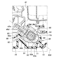
- the rear lower support portion 82 will be described.
- the rear corner of the bottom portion of the crankcase 46 of the engine 2 is parallel to each other and formed obliquely inward at an inclination angle of about 40 upward toward the front
- Two bottomed screw holes 46e are formed, and the mounting bracket 91 is fixed by two fastening bolts 90 screwed into these screw holes 46e.
- the two fastening bolts 90 have mutually parallel axes 90X orthogonal to the mating surface 46b (FIG. 4) of the crankcase 46. That is, the screw hole 46e is also orthogonal to the mating surface 46b as the insertion hole of the bolt 52 for fastening the lower half 46d of the crankcase 46 to the upper half 46c. Therefore, processing of the screw hole 46e is easy.
- the mounting bracket 91 has a base 92 formed with two through holes 92 a for inserting these fastening bolts 90, and extends rearward and downward from the base 92 from an opening 66 b formed in the rear lower portion of the shroud 66. It has two cylindrical parts 93 which define the attachment hole 93a which has an axis line which protrudes to the exterior and which extends in the left-right direction.
- the mounting bracket 91 supports the shroud 66 by the cylindrical portion 93 holding the edge of the opening 66 b of the shroud 66.
- the two cylindrical portions 93 are divided by a notch 93b provided on the axis 90X of the fastening bolt 90, and the portions on the base 92 side excluding the notch 93b are integrated with each other.
- the notch 93 b is sized to allow insertion of the fastening bolt 90 and to allow access of a tool that engages with the head when attaching and detaching the fastening bolt 90. That is, the two through holes 92a are provided in a portion of the base 92 between the two cylindrical portions 93 aligned with the notch 93b, whereby the enlargement of the mounting bracket 91 is suppressed.
- a pair of left and right cylindrical rubber bushes 94 are fitted into these cylindrical portions 93 so that a part of the axial direction is inserted.
- a pair of left and right mounting ribs 11b which form a mount portion, are formed to project upward from the rear upper surface of the undercover 16.
- the collar 95 inserted into the support hole 11d provided in the pair of mounting ribs 11b is supported at both ends by the support hole 11d, and the pair of rubber bushes 94 sandwiched between the left and right pair of washers 98 is Support on the outer periphery of the middle part.
- a shroud 66 is secured by fastening a mounting bolt 96 inserted from a mounting boss 11 a formed on the right side cover 13 and penetrating the collar 95 to a buried nut 97 provided on the mounting boss 11 a formed on the left side cover 12.
- the mounting bracket 91 exposed from the above is elastically supported by the undercover 16 via the rubber bush 94. Thereby, the transmission of the vibration of the engine 2 to the case 11 is suppressed. Further, since the collar 95 is provided inside the rubber bush 94 and the mount bolt 96 is provided on the collar 95, the rubber bush 94 is not pressed against the mount bolt 96 by the tightening of the mount bolt 96. Therefore, the mounting bolt 96 can be securely fastened to the embedded nut 97.
- a mounting bolt 96 and a collar 95 surrounding the mounting bolt 96 extend in the horizontal direction (a direction perpendicular to a vertical plane passing through the axis of the cylinder 47a).
- the two cylindrical portions 93 surround the axially intermediate portion of the mounting bolt 96 and the collar 95, and are attached to the mounting boss 11 a via the mounting bolt 96 and the collar 95.
- the axis 90X of the fastening bolt 90 is orthogonal to the mating surface 46b (FIG. 4) of the crankcase 46 and orthogonal to the collar 95 and the mounting bolt 96.
- the collar 95 and the mounting bolt 96 at least partially overlap the fastening bolt 90.
- a mounting bracket 71 a is integrally formed on the lower portion of the fan cover 71.
- a pair of left and right mounting ribs 11c which form a mount portion, are formed to project upward from the front upper surface of the undercover 16.
- the mounting bracket 71a is elastically supported by a pair of left and right mounting ribs 11c via a mounting bolt 96 and a rubber bush 94.
- the supporting structure of the mounting bracket 71 a is substantially the same as the supporting structure of the mounting bracket 91.
- the front of the undercover 16 supporting the lower front of the power generation unit 4 is connected to the front of the carrying handle 17 via the high rigidity left and right reinforcing frames 26.
- the carrying handle 17 disperses and supports the load in the front-rear direction without the left side cover 12 and the right side cover 13 bearing a load. Therefore, the bending stress generated near the carrying handle 17 in the case 11 is reduced.
- the power generation unit 4 is elastically supported by the case 11 at three locations, the upper support 81, the rear lower support 82, and the front lower support 83, the load of the power generation unit 4 is dispersed to each portion of the case 11. .
- the vibration absorbing action of the rubber bushes 85, 94, 94 not only suppresses the vibration transmission to the carrying handle 17 of the engine 2, but also prevents the resonance of the case 11 due to the vibration of the engine 2.
- the left side cover 12 and the right side cover 13 can be separated from the undercover 16 simply by removing the four bolts 29, 96.
- the engine 2 and the generator 3 can be exposed for easy maintenance without the generator 1 being turned over.
- the fastening bolt 90 for fastening the mounting bracket 91 to the crankcase 46 is inserted through the through hole 92 a of the mounting bracket 91 and diagonally inward at the corner of the bottom of the crankcase 46 Since the screw hole 46e formed in a direction is screwed, the space in the case 11 can be widened without reducing the support rigidity of the rear lower support portion 82. That is, as shown by an imaginary line in FIG. 6, when the mounting bracket 91 horizontally projects rearward, the position of the mounting bracket 91 is relatively high, and the space above it is relatively small. On the other hand, when the mounting bracket 91 is shifted downward by the above configuration, the space in the case 11 becomes wider by this amount.
- the muffler 61 disposed on the upper side of the mounting bracket 91 in the case 11 can be increased in size by that amount.
- the exhaust gas purification performance can be enhanced by enlarging the exhaust catalyst 62 without reducing the muffling effect of the muffler 61.
- the present invention can be widely modified and implemented without being limited to the above embodiment.
- the present invention is applied to the engine generator 1 as an example in the above embodiment, the present invention may be applied to other engine work machines such as an engine pump and a construction machine, and a separate work machine is driven.
- the present invention may be applied to an engine device provided with an engine for
- specific configurations and arrangements of each member and part, quantity, angle, and the like can be appropriately changed without departing from the scope of the present invention.
- not all of the components shown in the above embodiment are necessarily essential, and can be selected as appropriate.
Landscapes
- Engineering & Computer Science (AREA)
- Chemical & Material Sciences (AREA)
- Combustion & Propulsion (AREA)
- Mechanical Engineering (AREA)
- General Engineering & Computer Science (AREA)
- Chemical Kinetics & Catalysis (AREA)
- Health & Medical Sciences (AREA)
- Toxicology (AREA)
- Cylinder Crankcases Of Internal Combustion Engines (AREA)
- Vibration Prevention Devices (AREA)
Abstract
La présente invention concerne un dispositif de type moteur qui peut élargir l'espace interne d'un carter sans réduire la rigidité de support. Selon la présente invention, un moteur (2) comprend : une nervure de montage (11) qui est une partie de montage, qui est montée sur un carter (11) par l'intermédiaire d'une pluralité de parties de support (81, 82) et dans laquelle une partie de support inférieure arrière (82) est installée dans le carter (11) en tant qu'une des parties de support ; et un support de montage (91) qui est fixé à une partie inférieure d'un carter de vilebrequin (46) par un boulon de fixation (90) et est monté sur la nervure de montage (11), le boulon de fixation (90) étant inséré à travers un trou traversant (92) disposé dans le support de montage (91) et étant vissé dans un trou de vis (46e) qui est formé au niveau d'une section coin de la partie inférieure du carter de vilebrequin (46) dans une direction oblique vers l'intérieur.
Priority Applications (5)
| Application Number | Priority Date | Filing Date | Title |
|---|---|---|---|
| PCT/JP2017/044444 WO2019116434A1 (fr) | 2017-12-11 | 2017-12-11 | Dispositif de type moteur |
| JP2019559437A JP6773921B2 (ja) | 2017-12-11 | 2017-12-11 | エンジン装置 |
| EP17934924.6A EP3693569B1 (fr) | 2017-12-11 | 2017-12-11 | Dispositif de type moteur |
| CN201780097356.3A CN111433444B (zh) | 2017-12-11 | 2017-12-11 | 发动机装置 |
| US16/758,931 US11143139B2 (en) | 2017-12-11 | 2017-12-11 | Engine device |
Applications Claiming Priority (1)
| Application Number | Priority Date | Filing Date | Title |
|---|---|---|---|
| PCT/JP2017/044444 WO2019116434A1 (fr) | 2017-12-11 | 2017-12-11 | Dispositif de type moteur |
Publications (1)
| Publication Number | Publication Date |
|---|---|
| WO2019116434A1 true WO2019116434A1 (fr) | 2019-06-20 |
Family
ID=66819053
Family Applications (1)
| Application Number | Title | Priority Date | Filing Date |
|---|---|---|---|
| PCT/JP2017/044444 Ceased WO2019116434A1 (fr) | 2017-12-11 | 2017-12-11 | Dispositif de type moteur |
Country Status (5)
| Country | Link |
|---|---|
| US (1) | US11143139B2 (fr) |
| EP (1) | EP3693569B1 (fr) |
| JP (1) | JP6773921B2 (fr) |
| CN (1) | CN111433444B (fr) |
| WO (1) | WO2019116434A1 (fr) |
Families Citing this family (2)
| Publication number | Priority date | Publication date | Assignee | Title |
|---|---|---|---|---|
| CN113357039B (zh) * | 2021-07-19 | 2022-06-03 | 赣州市领沃电子科技有限公司 | 一种可拆卸式发动机线束塑壳保护外壳 |
| US11732634B1 (en) * | 2022-05-25 | 2023-08-22 | Kawasaki Motors, Ltd. | Engine |
Citations (8)
| Publication number | Priority date | Publication date | Assignee | Title |
|---|---|---|---|---|
| JPH017919Y2 (fr) * | 1984-07-31 | 1989-03-02 | ||
| JPH10121959A (ja) * | 1996-10-15 | 1998-05-12 | Yamaha Motor Co Ltd | 多気筒内燃機関の水冷却装置 |
| JP2001027127A (ja) | 1999-07-12 | 2001-01-30 | Honda Motor Co Ltd | エンジン作業機 |
| JP3340665B2 (ja) * | 1998-01-19 | 2002-11-05 | 本田技研工業株式会社 | エンジン作業機 |
| JP3871829B2 (ja) * | 1999-07-12 | 2007-01-24 | 本田技研工業株式会社 | エンジン発電機 |
| JP2017160833A (ja) * | 2016-03-09 | 2017-09-14 | 本田技研工業株式会社 | オーバーヘッドカムシャフト式エンジン |
| JP2017166400A (ja) * | 2016-03-16 | 2017-09-21 | 本田技研工業株式会社 | エンジン駆動作業機 |
| JP2017166397A (ja) * | 2016-03-15 | 2017-09-21 | 本田技研工業株式会社 | エンジン駆動作業機 |
Family Cites Families (12)
| Publication number | Priority date | Publication date | Assignee | Title |
|---|---|---|---|---|
| US2287399A (en) * | 1939-12-23 | 1942-06-23 | Packard Motor Car Co | Internal combustion engine |
| JPS6140425A (ja) * | 1984-07-31 | 1986-02-26 | Yanmar Diesel Engine Co Ltd | ケ−ス収容型エンジン発電機 |
| US4729353A (en) * | 1986-12-29 | 1988-03-08 | Engineered Air Systems, Inc. | Fuel container support system for a combustion engine |
| DE4413255A1 (de) * | 1994-04-16 | 1995-10-19 | Bayerische Motoren Werke Ag | Verfahren zum Bruchtrennen des Lagerdeckels einer mehrteiligen Lageranordnung, insbesondere in Kurbelgehäusen von Brennkraftmaschinen |
| JP3418079B2 (ja) * | 1997-01-24 | 2003-06-16 | 澤藤電機株式会社 | 発動発電機 |
| JP3347044B2 (ja) * | 1998-01-19 | 2002-11-20 | 本田技研工業株式会社 | 携帯用エンジン作業機 |
| JP3886002B2 (ja) * | 2002-03-27 | 2007-02-28 | ヤマハ発動機株式会社 | エンジン発電機 |
| CN100427746C (zh) * | 2006-09-30 | 2008-10-22 | 无锡开普动力有限公司 | 四冲程发动机 |
| JP4475327B2 (ja) * | 2007-12-21 | 2010-06-09 | トヨタ自動車株式会社 | ブラケットの締結構造 |
| CN103016138A (zh) * | 2012-11-07 | 2013-04-03 | 沈阳航天三菱汽车发动机制造有限公司 | 涡轮增压发动机 |
| JP6839923B2 (ja) * | 2016-03-11 | 2021-03-10 | 三菱重工サーマルシステムズ株式会社 | 車載装置および電動圧縮機 |
| CN205663509U (zh) * | 2016-06-03 | 2016-10-26 | 韩群山 | 增程式电混发电机与发动机曲轴联接装置 |
-
2017
- 2017-12-11 EP EP17934924.6A patent/EP3693569B1/fr active Active
- 2017-12-11 JP JP2019559437A patent/JP6773921B2/ja active Active
- 2017-12-11 WO PCT/JP2017/044444 patent/WO2019116434A1/fr not_active Ceased
- 2017-12-11 US US16/758,931 patent/US11143139B2/en active Active
- 2017-12-11 CN CN201780097356.3A patent/CN111433444B/zh not_active Expired - Fee Related
Patent Citations (8)
| Publication number | Priority date | Publication date | Assignee | Title |
|---|---|---|---|---|
| JPH017919Y2 (fr) * | 1984-07-31 | 1989-03-02 | ||
| JPH10121959A (ja) * | 1996-10-15 | 1998-05-12 | Yamaha Motor Co Ltd | 多気筒内燃機関の水冷却装置 |
| JP3340665B2 (ja) * | 1998-01-19 | 2002-11-05 | 本田技研工業株式会社 | エンジン作業機 |
| JP2001027127A (ja) | 1999-07-12 | 2001-01-30 | Honda Motor Co Ltd | エンジン作業機 |
| JP3871829B2 (ja) * | 1999-07-12 | 2007-01-24 | 本田技研工業株式会社 | エンジン発電機 |
| JP2017160833A (ja) * | 2016-03-09 | 2017-09-14 | 本田技研工業株式会社 | オーバーヘッドカムシャフト式エンジン |
| JP2017166397A (ja) * | 2016-03-15 | 2017-09-21 | 本田技研工業株式会社 | エンジン駆動作業機 |
| JP2017166400A (ja) * | 2016-03-16 | 2017-09-21 | 本田技研工業株式会社 | エンジン駆動作業機 |
Non-Patent Citations (1)
| Title |
|---|
| See also references of EP3693569A4 |
Also Published As
| Publication number | Publication date |
|---|---|
| EP3693569A1 (fr) | 2020-08-12 |
| JP6773921B2 (ja) | 2020-10-21 |
| CN111433444A (zh) | 2020-07-17 |
| US11143139B2 (en) | 2021-10-12 |
| EP3693569B1 (fr) | 2022-04-20 |
| JPWO2019116434A1 (ja) | 2020-07-16 |
| EP3693569A4 (fr) | 2020-10-28 |
| CN111433444B (zh) | 2021-09-03 |
| US20200309062A1 (en) | 2020-10-01 |
Similar Documents
| Publication | Publication Date | Title |
|---|---|---|
| KR100394383B1 (ko) | 엔진 발전기 | |
| CN100504051C (zh) | 发动机驱动装置 | |
| JP4210571B2 (ja) | エンジン駆動式作業機 | |
| CN101066702B (zh) | 船外机 | |
| JP6773921B2 (ja) | エンジン装置 | |
| JP4145912B2 (ja) | エンジン作業機 | |
| JP4359265B2 (ja) | 汎用エンジンのマフラカバー構造 | |
| JP3585773B2 (ja) | エンジン発電機 | |
| JP3754697B2 (ja) | エンジン作業機 | |
| JP2001027126A (ja) | エンジン発電機 | |
| JP4145911B2 (ja) | エンジン作業機 | |
| JP2722089B2 (ja) | エンジン作業機組立体 | |
| JPH11334389A (ja) | 傾斜単気筒水冷式内燃機関 | |
| JP2665677B2 (ja) | エンジン作業機組立体 | |
| JP2004353677A5 (fr) | ||
| JP2005282581A (ja) | エンジン作業機 | |
| JPH0264226A (ja) | 携帯形電源装置 |
Legal Events
| Date | Code | Title | Description |
|---|---|---|---|
| 121 | Ep: the epo has been informed by wipo that ep was designated in this application |
Ref document number: 17934924 Country of ref document: EP Kind code of ref document: A1 |
|
| ENP | Entry into the national phase |
Ref document number: 2019559437 Country of ref document: JP Kind code of ref document: A |
|
| ENP | Entry into the national phase |
Ref document number: 2017934924 Country of ref document: EP Effective date: 20200505 |
|
| NENP | Non-entry into the national phase |
Ref country code: DE |